EP3876456B1 - Efficient automatic repeat request for free space optical communication - Google Patents
Efficient automatic repeat request for free space optical communication Download PDFInfo
- Publication number
- EP3876456B1 EP3876456B1 EP21163108.0A EP21163108A EP3876456B1 EP 3876456 B1 EP3876456 B1 EP 3876456B1 EP 21163108 A EP21163108 A EP 21163108A EP 3876456 B1 EP3876456 B1 EP 3876456B1
- Authority
- EP
- European Patent Office
- Prior art keywords
- frame
- data
- communication
- data transmission
- scrambling sequence
- Prior art date
- Legal status (The legal status is an assumption and is not a legal conclusion. Google has not performed a legal analysis and makes no representation as to the accuracy of the status listed.)
- Active
Links
- 230000006854 communication Effects 0.000 title claims description 137
- 238000004891 communication Methods 0.000 title claims description 136
- 230000003287 optical effect Effects 0.000 title claims description 45
- 239000000872 buffer Substances 0.000 claims description 58
- 230000005540 biological transmission Effects 0.000 claims description 42
- 238000000034 method Methods 0.000 claims description 36
- 238000012937 correction Methods 0.000 claims description 12
- 238000012545 processing Methods 0.000 claims description 8
- 238000004590 computer program Methods 0.000 claims 1
- 238000010586 diagram Methods 0.000 description 9
- 230000008569 process Effects 0.000 description 9
- 230000015654 memory Effects 0.000 description 6
- 238000013459 approach Methods 0.000 description 4
- 238000005516 engineering process Methods 0.000 description 4
- 239000005437 stratosphere Substances 0.000 description 4
- 238000011084 recovery Methods 0.000 description 3
- 230000003044 adaptive effect Effects 0.000 description 2
- 230000008878 coupling Effects 0.000 description 2
- 238000010168 coupling process Methods 0.000 description 2
- 238000005859 coupling reaction Methods 0.000 description 2
- 238000005562 fading Methods 0.000 description 2
- 238000012546 transfer Methods 0.000 description 2
- 230000002411 adverse Effects 0.000 description 1
- 238000007664 blowing Methods 0.000 description 1
- 230000010267 cellular communication Effects 0.000 description 1
- 238000001514 detection method Methods 0.000 description 1
- 230000000694 effects Effects 0.000 description 1
- 230000005672 electromagnetic field Effects 0.000 description 1
- 239000000284 extract Substances 0.000 description 1
- 239000000835 fiber Substances 0.000 description 1
- 230000006870 function Effects 0.000 description 1
- 238000003780 insertion Methods 0.000 description 1
- 230000037431 insertion Effects 0.000 description 1
- 239000003550 marker Substances 0.000 description 1
- 238000010295 mobile communication Methods 0.000 description 1
- 230000006855 networking Effects 0.000 description 1
- 239000013307 optical fiber Substances 0.000 description 1
- 230000001902 propagating effect Effects 0.000 description 1
- 230000005855 radiation Effects 0.000 description 1
- 230000000630 rising effect Effects 0.000 description 1
- 239000004065 semiconductor Substances 0.000 description 1
- 239000007787 solid Substances 0.000 description 1
Images


Classifications
-
- H—ELECTRICITY
- H04—ELECTRIC COMMUNICATION TECHNIQUE
- H04L—TRANSMISSION OF DIGITAL INFORMATION, e.g. TELEGRAPHIC COMMUNICATION
- H04L1/00—Arrangements for detecting or preventing errors in the information received
- H04L1/12—Arrangements for detecting or preventing errors in the information received by using return channel
- H04L1/16—Arrangements for detecting or preventing errors in the information received by using return channel in which the return channel carries supervisory signals, e.g. repetition request signals
- H04L1/18—Automatic repetition systems, e.g. Van Duuren systems
- H04L1/1829—Arrangements specially adapted for the receiver end
- H04L1/1864—ARQ related signaling
-
- H—ELECTRICITY
- H04—ELECTRIC COMMUNICATION TECHNIQUE
- H04B—TRANSMISSION
- H04B10/00—Transmission systems employing electromagnetic waves other than radio-waves, e.g. infrared, visible or ultraviolet light, or employing corpuscular radiation, e.g. quantum communication
- H04B10/11—Arrangements specific to free-space transmission, i.e. transmission through air or vacuum
- H04B10/112—Line-of-sight transmission over an extended range
- H04B10/1123—Bidirectional transmission
-
- H—ELECTRICITY
- H04—ELECTRIC COMMUNICATION TECHNIQUE
- H04L—TRANSMISSION OF DIGITAL INFORMATION, e.g. TELEGRAPHIC COMMUNICATION
- H04L1/00—Arrangements for detecting or preventing errors in the information received
- H04L1/12—Arrangements for detecting or preventing errors in the information received by using return channel
- H04L1/16—Arrangements for detecting or preventing errors in the information received by using return channel in which the return channel carries supervisory signals, e.g. repetition request signals
- H04L1/18—Automatic repetition systems, e.g. Van Duuren systems
- H04L1/1809—Selective-repeat protocols
-
- H—ELECTRICITY
- H04—ELECTRIC COMMUNICATION TECHNIQUE
- H04L—TRANSMISSION OF DIGITAL INFORMATION, e.g. TELEGRAPHIC COMMUNICATION
- H04L1/00—Arrangements for detecting or preventing errors in the information received
- H04L1/12—Arrangements for detecting or preventing errors in the information received by using return channel
- H04L1/16—Arrangements for detecting or preventing errors in the information received by using return channel in which the return channel carries supervisory signals, e.g. repetition request signals
- H04L1/18—Automatic repetition systems, e.g. Van Duuren systems
- H04L1/1829—Arrangements specially adapted for the receiver end
- H04L1/1835—Buffer management
- H04L1/1841—Resequencing
-
- H—ELECTRICITY
- H04—ELECTRIC COMMUNICATION TECHNIQUE
- H04L—TRANSMISSION OF DIGITAL INFORMATION, e.g. TELEGRAPHIC COMMUNICATION
- H04L1/00—Arrangements for detecting or preventing errors in the information received
- H04L1/12—Arrangements for detecting or preventing errors in the information received by using return channel
- H04L1/16—Arrangements for detecting or preventing errors in the information received by using return channel in which the return channel carries supervisory signals, e.g. repetition request signals
- H04L1/18—Automatic repetition systems, e.g. Van Duuren systems
- H04L1/1867—Arrangements specially adapted for the transmitter end
- H04L1/187—Details of sliding window management
-
- H—ELECTRICITY
- H04—ELECTRIC COMMUNICATION TECHNIQUE
- H04L—TRANSMISSION OF DIGITAL INFORMATION, e.g. TELEGRAPHIC COMMUNICATION
- H04L1/00—Arrangements for detecting or preventing errors in the information received
- H04L1/12—Arrangements for detecting or preventing errors in the information received by using return channel
- H04L1/16—Arrangements for detecting or preventing errors in the information received by using return channel in which the return channel carries supervisory signals, e.g. repetition request signals
- H04L1/18—Automatic repetition systems, e.g. Van Duuren systems
- H04L1/1867—Arrangements specially adapted for the transmitter end
- H04L1/1874—Buffer management
-
- H—ELECTRICITY
- H04—ELECTRIC COMMUNICATION TECHNIQUE
- H04L—TRANSMISSION OF DIGITAL INFORMATION, e.g. TELEGRAPHIC COMMUNICATION
- H04L1/00—Arrangements for detecting or preventing errors in the information received
- H04L1/12—Arrangements for detecting or preventing errors in the information received by using return channel
- H04L1/16—Arrangements for detecting or preventing errors in the information received by using return channel in which the return channel carries supervisory signals, e.g. repetition request signals
- H04L1/18—Automatic repetition systems, e.g. Van Duuren systems
- H04L1/1867—Arrangements specially adapted for the transmitter end
- H04L1/188—Time-out mechanisms
Definitions
- Communication terminals in a network or other system may transmit and receive optical signals through free space optical links.
- the optical signals are often sent as data frames. Reliable transmission and receipt of the data frames is necessary for the system to operate properly. Unfortunately, such frames may be lost or damaged in route due to a variety of reasons.
- One technique to address this problem is to encode the data with an error correction code (ECC) prior to transmission to enable correction of errors in transmission.
- ECC error correction code
- ARQ automatic repeat request
- the receiver device requests that the transmitter device resend a data frame that was received with an error.
- PRAKASH GEETHA ET AL “On the Improved Performance of Luby Transform Codes over Selective Repeat ARQ in Turbulent Free Space Optical Links” (2013 IEEE 16TH INTERNATIONAL CONFERENCE ON COMPUTATIONAL SCIENCE AND ENGINEERING, IEEE, 3 December 2013 ) describes the performance of Luby transform codes over selective repeat ARQ in turbulent free space optical links.
- the technology relates to a variety of FSOC-related techniques for use, by way of example, in a free-space optical communication system.
- FSOC free-space optical communication system.
- Other causes of received power fluctuations, such as scintillation, coupling losses, and other issues may also contribute to the loss of frames in bursts.
- the techniques described herein enable the system to quickly and efficiently recover from the loss or corruption of data frames by streamlining the retransmission process. This makes the overall communication process more robust, and also reduces overhead costs associated with unnecessary retransmissions.
- a communication network or other system may include optical communication links that are used to transfer data between various communication devices.
- the communication devices may be positioned on buildings, on the ground, or on moving devices (e.g., gimballed devices arranged on high-altitude platforms or satellites), although other structures in which to position communication devices are also envisioned.
- the communication links are used to transfer the data between the buildings, the ground, and the moving devices.
- Each optical link allows for communication between two communication devices.
- a transmitter device is configured to transmit an optical beam
- a receiver device is configured to detect the optical beam from the transmitter device and thus form the communication link.
- communication devices may function as transmitter and/or receiver devices at any given point in time.
- an example communication network 100 includes a variety of communication terminals such as stationary communication terminals 102 and 104, satellite 106, and high-altitude platforms (HAPs), such as an aircraft that may be an airplane or unmanned aerial vehicle (UAV) 108, as well as a communication balloon 110.
- One or more communication devices are associated with each communication terminal.
- the communication devices of the various communication terminals may communicate directly or indirectly with one another.
- the stationary communication terminals may be located on the rooftop of buildings or on the ground, although other locations are envisioned.
- the aircraft 108 may be a UAV or other aircraft without a human pilot onboard.
- the UAV may be autonomous, remotely piloted, or both.
- the communication balloon 110 may be released into the Earth's stratosphere, for instance to attain an altitude between 11 to 23 miles above the Earth's surface and provide connectivity for a ground area of 25 miles in diameter at speeds comparable to terrestrial wireless data services (such as, 3G or 4G).
- the communication balloons 110 may float in the stratosphere, in one example at an altitude twice as high as commercial airplanes and the weather (e.g., on the order of 20 km above the Earth's surface).
- the communication balloons 110 are carried around the earth by winds and can be steered by rising or descending to an altitude with winds moving in the desired direction. Winds in the stratosphere are usually steady and move slowly at about 5 and 20 mph, and each layer of wind varies in direction and magnitude.
- the stationary communication terminals 102, 104 may receive communication signals (shown as dotted lines in Fig. 1 ) from another stationary terminal (not shown), satellite 106, or HAP 108, and reroute the communication signal to another stationary terminal, satellite, or HAP.
- the HAPs 108 and/or other communication terminals 102, 104, 106 and 110 may be arranged in a mesh network or other configuration to provide communication services to an area of interest.
- the communication signals may be sent directly or indirectly from at least one communication terminal to one or more user devices 112 or 114, each of which may be associated with a user 116 or 118, respectively.
- the user device 112 may be a mobile phone in communication with communication terminal 102, for example via cellular communication.
- the user device 114 may be in communication with communication terminal 104, for example via a WiFi hotspot 120.
- the satellite 106 may be in Low Earth Orbit (LEO), Medium Earth Orbit (MEO), or High Earth Orbit (HEO), including Geosynchronous Earth Orbit (GEO).
- the HAPs 108 may operate at high altitudes (e.g., 17-22 km above the Earth's surface).
- the communication balloon 110 or UAV 108 may be configured to operate in the stratosphere to provide communication services to an area of interest.
- Such HAPs 108 may be released into the Earth's atmosphere, e.g., by launching from the ground, from an aircraft, or flown to the desired altitude.
- the communication network 100 employs FSOC, which is an optical communication technology that uses light propagating in free space to wirelessly transmit data for telecommunication or computer networking. Therefore, the communication network 100 is configured to transmit optical communication signals between pairs of the communication terminals as shown in Fig. 1 .
- FSOC optical communication technology that uses light propagating in free space to wirelessly transmit data for telecommunication or computer networking. Therefore, the communication network 100 is configured to transmit optical communication signals between pairs of the communication terminals as shown in Fig. 1 .
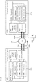
- this figure is a block diagram that illustrates an example pair of communication devices 200a and 200b.
- one or more communication devices are included in each of the communication terminals that employ FSOC.
- the communication devices 200a, 200b may be configured to establish optical communication links 202a and 202b between two communication terminals, allowing communication signals 204a and 204b to be transmitted from one communication terminal another.
- the communication signals 204 include data 206, such as Internet protocol (IP) packets, being routed via free space 208 across the communication network 100 (see Fig. 1 ).
- Each communication device 200 may include one or more processors 210, e.g., 210a or 210b and memory 220, e.g., 220a or 220b.
- the communication devices also include one or more transmitter devices 230, e.g., 230a or 230b and receiver devices 240, e.g., 240a or 240b, which may be arranged as transceivers 242, e.g., 242a and 242b.
- the communication devices also include an optical system 250, e.g., 250a or 250b, and pointing / steering hardware 260, e.g., 260a or 260b.
- the processor(s) 210 may comprise a central processing unit (CPU) or other microprocessor, dedicated field programmable gate array (FPGA) logic, other hardware-based processing components and any combination thereof.
- the one or more processors 210 are operatively coupled with memory 220 that non-transitorily stores information, such as instructions executable by the one or more processors 210.
- the memory 220 of each communication device 200 is also configured to store information regarding the data to be transmitted across the free space optical link.
- the memory 220 may comprise one or more memory modules either physically or logically arranged to include various buffers, which are described in detail below.
- the one or more processors 210 are operatively coupled with the transmitter device 230 and the receiver device 240.
- the one or more processors 210 may therefore be configured to transmit, via the transmitter device(s) 230, communications information and data in the form of optical beams, and also may be configured to receive, via the receiver device(s) 240, communications and data in the form of optical beams.
- Received optical beams may be processed by the one or more processors 210 to extract the communications information and data.
- the one or more processors 210 are further configured, in accordance with the extracted communications information and data, to implement various ARQ techniques. This may include determining whether to retransmit certain unacknowledged frames (e.g., one or more data packets) that are not currently in transit. It may also include adaptively varying a retransmission delay depending upon whether feedback has been provided by the receiver device. And it may further include providing a scrambling sequence to avoid the possibility of false frame markers. These ARQ techniques are discussed in detail below.
- the one or more processors 210 are also operatively coupled to the optics system 250 and may determine an adjusted position of the optics system 250 to establish a link 202. Furthermore, the one or more processors 210 are operatively coupled to the pointing /steering hardware 260 for adjusting the optics system 250, and may be configured to provide pointing adjustments of the optics system 250.
- the pointing/steering hardware 260 may be configured to move in at least two degrees of freedom, such as yaw and pitch. The adjustments to the optics system 250 may be made to establish acquisition and connection links with the other communication device 200.
- the transmitter device 230 may be a semi-conductor device, such as a light-emitting diode (LED) or a laser diode.
- the transmitter device 230 may be a fiber laser or a solid state laser.
- Laser diodes may be directly modulated, that is, the light output may be controlled by a current applied directly to the transmitter 230.
- the transmitter device 230 may be a single-mode laser diode that supports one optical mode, or the transmitter device 230 may be a multimode laser diode that supports multiple-transverse optical modes.
- An optical mode is a particular electromagnetic field pattern of radiation measured in a plane perpendicular ( i.e., transverse) to the propagation direction of the beam.
- the transmitter device 230 may receive a modulated communication signal from a modulator (not shown), which in turn receives an electrical signal, and modulates the electrical signal.
- the transmitter device 230 may receive the modulated electrical signal, convert the electrical signal into an optical communication beam, and output the optical communication beam into an optical fiber towards the optics system 250.
- the transmitter device 230 is also configured to output a beacon beam that allows one communication device to locate another.
- transmitter device 230b of the communication device 200b may output a beacon beam to enable the communication device 200a to locate device 200b and to establish a communication link 202a with the communication device 200b.
- the transmitter device 230a of the communication device 200a may similarly output a beacon beam to enable communication device 200b to locate device 200a and establish a communication link 202b with the communication device 200a.
- the communication links 202a, 202b may allow for communication signals 204a and 204b between the two communication devices 200a and 200b.
- the receiver device 240 includes a light position sensing device to detect the incoming optical beam.
- the light position sensing device includes, but is not limited to, a lateral position device, a charge-coupled Device (CCD) camera, a photodetector, or a quad-cell, to detect the optical beacon laser.
- CCD charge-coupled Device
- the receiver device 240 converts the received optical beam into an electric signal using the photoelectric effect.
- the optics system 250 is configured to transmit the optical beams, such as communication beams or beacon beams, as well as receive the optical beams and provide the received optical beams to the receiver device 240.
- the optics system 250 and/or the receiver device 240 may include, but are not limited to, a de-multiplexer, an optical pre-amplifier, photodiodes, the photoreceiver, transimpedance amplifiers, clock/phase recovery circuits, decision circuits, and/or forward error correction (FEC) circuits.
- FEC forward error correction
- Configurations of the optics system 250 may include transmitter optics that are separate from receiver optics.
- communication link 202a may be formed between transmitter optics of one communication device and receiver optics of another communication device.
- the communication device 200a may form a communication link 202a with the communication device 200b using transmitter optics in optics system 250a of the communication device 200a and receiver optics in optics system 250b of the second communication device 200b.
- the one or more processors 210a can send communication signals 204a that include data 206 to the communication device 200b.
- the transmitter optics in optics system 250b at the communication device 200b may transmit an optical beacon beam, which the receiver optics in optics system 250a at the communication device 200a locates and identifies to form a communication link 202b.
- the one or more processors 210b can send communication signals 204b that include data 206 to the communication device 200a.
- the communication devices 200 may be integrated in communication terminals including stationary communication terminals and mobile communication terminals such as HAPs 108.
- the one or more processors 210 in the communication device 200 of communication balloon 110 may be configured to determine a location and/or altitude the high-altitude balloon 110 needs to attain in order to provide appropriate communication coverage, for instance a particular position or station in a mesh network.
- the one or more processors 210 may further be configured to move the communication balloon 110 into a layer of wind blowing in a direction that may take the balloon where it should be going, thereby steering the communication balloon to the right location.
- each communication device 302 has an input buffer (IB) 304 (304a or 304b), an output buffer (OB) 306 (306a or 306b), a transmitter section 308 (308a or 308b) and a receiver section 310 (310a or 310b).
- IB input buffer
- OB output buffer
- the input buffers 304a and 304b and output buffers 306a and 306b may comprise portions of the memories 220a and 220b, respectively.
- the transmitter sections 308a and 308b may include transmitter devices 230a and 230b, respectively, as well as corresponding portions of the optics system 350a or 350b.
- the receiver sections 310a and 310b may include the receiver devices 240a and 240b, respectively, as well as corresponding portions of the optics system 350a or 350b.
- transmitter 308a of communication device 302a is configured to send data frames to the receiver 310b of communication device 302b via optical communication link 312a.
- the transmitter 308b of communication device 302b is configured to send acknowledgement frames and other information to the receiver 310a of the communication device 302a via optical communication link 312b.
- the communication device 302b may provide sequence information (h,r,d) to the communication device 302a conveying the current state of a resequencing buffer, so that the processor(s) of communication device 302a can implement certain ARQ techniques as explained in detail below.
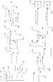
- FIGs. 4A-C these figures illustrate an example transmitter module 400 and an example receiver module 440 that respectively assemble and disassemble data frames, along with an example frame configuration.
- the modules implement certain functionality of the transmitters 308a and 308b and receivers 310a and 310b of Fig. 3 , and corresponding functionality of the transmitter devices 230a and 230b, and the receiver devices 240a and 240b of Fig. 2 .
- the transmitter module 400 includes a frame source 402 and multiplexer 404, 406 and 408.
- the frame source 402 includes input buffer 410 and a retransmission buffer (RT) 412.
- RT retransmission buffer
- ARQ logic of the processor(s) can select a frame for transmission from the input buffer 410 or the retransmission buffer 412, or as an idle frame 414.
- the frame source 402 provides the selected frame to the multiplexer 404, including, e.g., an idle frame flag (id), a sequence number (SN), frame information such as frame length (1) and a frame data field (d), as well as fill bytes (f), as needed.
- the multiplexer 404 multiplexes the frame with data from a resequencing buffer (RS) to obtain first multiplexed information 418.
- This data includes resequencing head information (h rs ), resequencing received information (r rs ), and resequencing delivered information (d rs ), which conveys the current state of the resequencing buffer to the receiver.
- the h rs , r rs and d rs information may comprise sequence numbers.
- a scrambling sequence supplied by scrambler 420 is applied via node 422 to the first multiplexed information 418, resulting in a scrambled block 424.
- the scrambler 420 may be a linear feedback shift register (LFSR)-based scrambler.
- the multiplexer 406 prepends the initial state of the scrambler 420 to the header of the scrambled block 424, resulting in second multiplexed information 426.
- LFSR linear feedback shift register
- the second multiplexed information 426 is encoded with an error correction code, such as a Reed-Solomon ECC at encoding block 428.
- the encoder computes 32 parity bytes for a block of 223 information bytes, and the codeword length is thus 255 bytes.
- the multiplexer 408 prepends a frame sync marker (s) to the ECC encoded data 430, forming a frame 432 ready for transmission via FSOC.
- Fig. 4B this figure illustrates one possible frame format in accordance with aspects of the disclosure.
- the units are of bytes (8, 1, 32, ...), or bits (15b, 1 b ).
- FS frame sync
- l i length field of the ith packet
- d i ith packet (information bytes)
- f fill bytes
- p i parity bytes of ith codeword. Parity bytes are inserted every 223 bytes (exclusive of the parity bytes themselves) according to the ECC.
- the minimum frame length is preferably 255 bytes and the maximum frame length is 3570 bytes.
- a frame contains P packets.
- the number of packets is determined by the incoming packet stream and takes values in ⁇ 1, 2, ... , 23 ⁇ .
- Packets are added to a frame with a 2-byte length field encoding the packet length.
- the length field of the ith packet is denoted l i and the l i -byte packet is denoted d i .
- packets are collected to form a frame until the length fields and packet data exceeds 1480 bytes, i.e.,
- the frame ⁇ id , (1, d), f ⁇ is prepended with the assigned sequence number and the 6-byte current state (h rs , r rs , d rs ) of the resequencing buffer.
- the block is scrambled.
- the initial 2-byte scrambler state or seed is prepended to the block (the state is not scrambled).
- Every block of 223 scrambled bytes are encoded by the RS code, producing 32 parity bytes.
- the 32 parity bytes are inserted after the 223 bytes they encode (parity bytes are not scrambled).
- the minimum frame length is 255 bytes. With a maximum input packet length of 1520 bytes, the maximum frame length is 3570 bytes.
- FIG. 4C illustrates data processing at the receiver module 440.
- codewords with more than 16 byte errors are detected by the decoder and flagged as unreliable codewords. If any of the K codewords in a frame is flagged as unreliable, the entire frame is discarded. In conjunction with the codewords being decoded, the parity bytes are stripped out by the decoder. Assuming there are no errors or that the errors were correctable, the ECC decoding block extracts and outputs the scrambler seed 448 to descrambler 450, and also outputs the decoded data stream 452 to node 454.
- the scrambler seed is used to initialize the descrambler 450, which then descrambles the frame at node 454.
- This information is demultiplexed at block 456, which outputs certain information to the resequencing buffer RS at block 458 and the retransmission buffer RT at block 460.
- the sequence numbers ⁇ h rs , r rs , d rs ⁇ are stripped out and sent to the RT to update the retransmission state.
- the frame data frame length (1) and a frame data field (d)
- sequence number SN are transmitted to the RS.
- ARQ operation includes the following.
- incoming frames are held in the input buffer IB until requested for transmission.
- Frames that have been transmitted and may be unresolved are held in the retransmission buffer RT.
- a frame is considered resolved at the transmitter if it has been transmitted and acknowledged (ACK'd).
- ACK'd acknowledges
- a frame is considered to be unresolved if it has been transmitted but not ACK'd.
- incoming frames are held in the resequencing buffer RS.
- the RS infers lost frames from incoming traffic. Frames received in order and which are error free are delivered from the RS buffer to the outgoing Ethernet stream. The state of the RS is transmitted back to the transmitter with return traffic.
- block-selective ARQ One approach that can be implemented with the aforementioned configurations is block-selective ARQ. As noted above, it is possible to lose data frames in bursts for various reasons. For instance, there may be a pointing error in which the optical link is lost. Other causes of received power fluctuations, such as scintillation, coupling losses, and other issues may also contribute to the loss of frames in bursts. To address these problems, block-selective ARQ may be employed. This technique is suitable for fast and slow-fading channels and has lower complexity than conventional Selective-Repeat (SR) and better performance than Go-Back-N (GbN) techniques.
- SR Selective-Repeat
- GbN Go-Back-N
- Block-selective ARQ acknowledges variable length blocks of frames in the return stream from the receiver to the transmitter.
- all received frames are held in the RS.
- Frames that are received in order and that are error free are then forwarded from the RS to an output buffer OB for insertion into an outgoing Ethernet stream, which may be provided to another communication terminal or to an end user.
- the processor(s) in conjunction with the RS infers lost frames from the received incoming traffic.
- the receiver tracks the most advanced received frame h (with respect to the sequence number), the most recent received frame r, and the oldest frame not forwarded (or delivered) d, as shown in Fig. 3 .
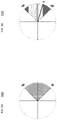
- the first representation 500 ( Fig. 5A ) illustrates how a first communication device sending frames to a second communication device (e.g., communication devices 302a and 302b, respectively, of Fig. 3 ) may keep track of various transmitted data frames.
- h indicates the most advanced transmitted frame
- u indicates the oldest unacknowledged (unresolved) frame. Frames in the shaded region between h and u may be in transit, lost, or acknowledged.
- the second representation 510 ( Fig. 5B ) illustrates how the second communication device may keep track of various received data frames.
- h indicated the most advanced received frame
- d indicates the oldest frame not delivered
- r indicates the most recent received frame based on the information in the resequencing buffer RS of the second communication device.
- the state of the RS, conveyed by (h,r,d) is sent back to the transmit side with return traffic. This acts as a collection of ACKs to the transmit side.
- the sequence numbers (h,r,d) are embedded in the return data, in particular the header of a frame. If there is no return data, an idle frame is generated and (h,r,d) is embedded in the idle frame.
- the system may infer a lack of acknowledgement for a particular frame by the absence of an ACK according to the (h,r,d) data, and thereby implement an ARQ process to retransmit the frame.
- the window size is set to accommodate the maximum lost duration.
- the input buffer IB holds frames that have not been transmitted.
- the input buffer is configured as a first-in-first-out queue.
- Head and tail pointers h ib and t ib track the state of the input buffer and wrap modulo the maximum input buffer index.
- the two addresses ⁇ h rt , u rt ⁇ track the RT buffer state. Frames from [t rt , u rt - 1] have been resolved (e.g., delivered or skipped over).
- the resequencing buffer RS holds frames that have been received but may not be delivered (e.g., due to being received in error or out-of-order). Also in this scenario, the state of the RS buffer is tracked with the three sequence numbers: ⁇ h rs , r rs , d rs ⁇ .
- h rs is the most advanced frame received
- d rs is the next frame to be delivered
- r rs is the most recently received frame.
- h rs and r rs always point to error-free frames, all frames from [t rs , d rs - 1] have been resolved (either delivered or timed out), and d rs points to a frame that has not been received (in the case where the entire window is delivered, d rs points to h rs + 1).
- frames are delivered once they are received in order.
- the delivered address d rs is advanced to point to the next frame to be delivered.
- the system uses the received RS state information and tracks the most advanced transmitted frame (h) and the oldest unresolved (un-ACK'd) frame (u), as seen in Fig. 5A .
- the transmitter is configured to transmit the oldest unacknowledged frame that is not currently in transit.
- the retransmission delay is the minimum time the transmitter waits before inferring that a frame was lost (and making it a candidate for retransmission).
- the retransmission delay is nominally set to the round trip time (RTT).
- RTT round trip time
- the system can erroneously retransmit a frame that was received correctly. This adversely affects the efficiency of the system, because the transmitter expends processing and transmission resources on the retransmission of a properly received frame instead of sending a new frame.
- the system allows the retransmission delay to grow in the absence of feedback by the receiver, up to some defined limit.
- the transmitter will reset the delay.
- a frame is stored in the RT and the time at which the frame was transmitted (T tmt ) is recorded, e.g., in that buffer.
- the RT holds the frame state, sequence number and the T tmt .
- A acknowledged (i.e., ACK)
- C cleared for re-use
- U unresolved.
- each column corresponds to a single frame
- h rt is the most advanced sequence number transmitted
- u rt is the least advanced sequence number that is unresolved.
- T lost is the lost duration and RTT is the round-trip-time.
- h rs is the most advanced sequence number received (ACK'd)
- r rs is the most recent received SN
- d rs is the next SN to be delivered.
- the processing system of the transmitter may determine to retransmit the selected frame.
- the typical RTT is between 0-1.3 ms, and T lost may be between the RTT and 10 ms.
- the RTT may exceed 1.3 ms, for instance being between 1.0 ms and 5 ms, or less than 10 ms.
- T lost may similarly exceed 10 ms, for instance being between 10-25 ms, or less than 40 ms.
- Other FSOC situations may have even larger (or smaller) RTT and T lost times.
- time to wait ( ⁇ ) RTT + ⁇ , where ⁇ is the time that the return traffic (e.g., acknowledgements) has been down or otherwise not received correctly.
- ⁇ is the time that the return traffic (e.g., acknowledgements) has been down or otherwise not received correctly.
- the RT buffer is updated.
- the lost duration may first be set to the minimum value RTT (which is thought of as including processing delay). Frames having addresses falling outside the transmitter window (based on the values ⁇ h rs , r rs , d rs ⁇ ) are ignored. When the oldest (with respect to sequence number) unresolved frame is acknowledged, the window for frames under consideration advances.
- the system in addition has a timeout T out .
- frames that have been in the RT longer than T out are no longer candidates for re-transmission.
- T out timeout
- frames that have been in the RT longer than T out are no longer candidates for re-transmission.
- a frame has been in the RT longer than T out its state is changed from U (unacknowledged) or A (acknowledged) to C (cleared for reuse).
- U unacknowledged
- A acknowledged
- C lasnowledged
- the N win window is much smaller than the number of valid sequence numbers.
- the RS When the RS receives such a sequence number, it advances its window to accommodate the new frame. This may cause it to advance the d rs pointer, in which case it resets the states of all frames that d rs advances over to D (delivered). In this way the RS buffer does not hang up on a frame that the RT is no longer transmitting.
- the system may take this information into account to have the timeout occur more quickly, or possibly never time out. For example, latency constrained traffic can have a timeout of zero, so they are never retransmitted.
- a line code may be used to avoid long runs of Is or 0s in the data, and also to ensure that the data is DC balanced.
- the line code helps the system with clock and data recovery.
- a digital communication system also requires a method to locate the start and end of a frame. This can be facilitated by embedding in the data sequence a special frame sync (FS) sequence.
- FS frame sync
- the line code may also be designed to prohibit the occurrence of the FS in the data. But the line code also introduces overhead, coding complexity and error propagation in decoding. These can significantly affect performance of the communication system.
- a scrambling sequence may be used instead of a line code. With a scrambling sequence the data is combined with the scrambling sequence, for example by modulo-two addition of bits, so that the data is more likely to appear random.
- the scrambling sequence which has a rate one, still allows for the possibility that a sync appears in the data (or a problematic run of Is or 0s).
- a false FS e.g., duplicate
- the receiver may inaccurately lock to it and the frame will be lost.
- the false FS problem is addressed here by using a different seed for the scrambling sequence when a frame is retransmitted. Thus, should the frame be lost and need to be retransmitted, it will have a different scrambling sequence applied to it. It is highly unlikely a false FS will appear when the data is scrambled with the different sequence.
- the scrambling seed is embedded within the frame for recovery by the receiver. Referring back to Fig. 4A , this is shown in which the scrambling sequence or seed (r) from the scrambler 420 is applied to the frame to be transmitted prior to application of the error correction code.
- this figure illustrates one embodiment of the scrambler 420, in particular using a linear feedback shift register (LFSR).
- LFSR linear feedback shift register
- the scrambling sequence is generated by the LFSR having a particular feedback polynomial.
- the result is a 2-byte scrambler state (or seed field) prepended to the frame, with the first scrambled bit being the idle field.
- the feedback polynomial may be: z 15 + z 1 + z 0 .
- Other feedback polynomials can also be employed.
- the LFSR state changes at every iteration, the scrambler sequence changes accordingly from one frame to a subsequent frame.
- the ECC is applied and the data block is transmitted to the receiver, for instance as described above with regard to node 422 of Fig. 4A .
- the scrambling seed r is extracted as shown in Fig. 4C and is used to initialize the descrambler.
- the appropriate scrambler state is regenerated at that point, as the scrambler state does not need to be stored. With this approach, a line code may be omitted, resulting in reduced overhead, coding simplification and avoidance of error propagation in decoding.
- FIG. 10 illustrates process 1000, which involves transmitting one or more frames to a receiver device of a free-space optical communication system in block 1002.
- the frame(s) is stored in a retransmission buffer at block 1004, and in block 1006 the system obtains current state information identifying a current state of a resequencing buffer.
- the process tracks a most advanced transmitted frame and an oldest unresolved frame in accordance with the current state information.
- the system selects a frame for transmission according to the tracked most advanced transmitted frame and the oldest unresolved fame.
- the frame of interest is retrieved from the retransmission buffer, and in block 1014 the retrieved frame is transmitted to the receiver device using FSOC.
- this figure illustrates process 1100, in which one or more frames are transmitted to a receiver device of a free-space optical communication system in block 1102.
- the frame(s) is stored in a retransmission buffer.
- a frame state, time of transmission and sequence number are associated with each respective frame stored in the retransmission buffer.
- the system determines whether to retransmit a given frame stored in the retransmission buffer by evaluating whether a time since a last transmission exceeds a loss time (T lost ).
- T lost loss time
- T lost t min RTT + t ⁇ t ′ , T lost , max where t is a current time, t' is a time at which a last feedback frame was correctly received by the transmitter device, and RTT is an estimated round trip time.
- the system selects a given one of the frames stored in the retransmission buffer, and in block 1112 the system retransmits the selected frame to the receiver device.
- this figure illustrates process 1200, which involves selecting a data frame for transmission to a receiver device per block 1202.
- the system prepends a current state of a resequencing buffer to the data frame to form an information block in block 1204, and scrambles the information block with a scrambling sequence to generate scrambled data in block 1206.
- the system applies an error correction code to the scrambled data to obtain a frame, and in block 1210 transmits the frame to a receiver device of the free-space optical communication system.
- the features described above may provide efficient approaches to handle ARQ retransmissions of frames between two communication devices in a FSOC system. These techniques reduce system overhead and processing costs, and ensure more reliable transmission and reception of information.
- the various techniques can be used individually or in any combination, resulting in a robust communication architecture that can handle slow fading and other burst frame loss situations.
- the present technology enjoys wide industrial applicability including, but not limited to, reliable data transmission in free-space optical communication systems.
Landscapes
- Engineering & Computer Science (AREA)
- Computer Networks & Wireless Communication (AREA)
- Signal Processing (AREA)
- Physics & Mathematics (AREA)
- Electromagnetism (AREA)
- Detection And Prevention Of Errors In Transmission (AREA)
- Optical Communication System (AREA)
Applications Claiming Priority (3)
| Application Number | Priority Date | Filing Date | Title |
|---|---|---|---|
| US15/393,377 US10291365B2 (en) | 2016-12-29 | 2016-12-29 | Efficient automatic repeat request for free space optical communication |
| EP17829558.0A EP3563507B1 (en) | 2016-12-29 | 2017-12-21 | Efficient automatic repeat request for free space optical communication |
| PCT/US2017/067919 WO2018125751A2 (en) | 2016-12-29 | 2017-12-21 | Efficient automatic repeat request for free space optical communication |
Related Parent Applications (2)
| Application Number | Title | Priority Date | Filing Date |
|---|---|---|---|
| EP17829558.0A Division EP3563507B1 (en) | 2016-12-29 | 2017-12-21 | Efficient automatic repeat request for free space optical communication |
| EP17829558.0A Division-Into EP3563507B1 (en) | 2016-12-29 | 2017-12-21 | Efficient automatic repeat request for free space optical communication |
Publications (2)
| Publication Number | Publication Date |
|---|---|
| EP3876456A1 EP3876456A1 (en) | 2021-09-08 |
| EP3876456B1 true EP3876456B1 (en) | 2022-11-30 |
Family
ID=60972512
Family Applications (3)
| Application Number | Title | Priority Date | Filing Date |
|---|---|---|---|
| EP21162993.6A Active EP3855657B1 (en) | 2016-12-29 | 2017-12-21 | Efficient automatic repeat request for free space optical communication |
| EP21163108.0A Active EP3876456B1 (en) | 2016-12-29 | 2017-12-21 | Efficient automatic repeat request for free space optical communication |
| EP17829558.0A Active EP3563507B1 (en) | 2016-12-29 | 2017-12-21 | Efficient automatic repeat request for free space optical communication |
Family Applications Before (1)
| Application Number | Title | Priority Date | Filing Date |
|---|---|---|---|
| EP21162993.6A Active EP3855657B1 (en) | 2016-12-29 | 2017-12-21 | Efficient automatic repeat request for free space optical communication |
Family Applications After (1)
| Application Number | Title | Priority Date | Filing Date |
|---|---|---|---|
| EP17829558.0A Active EP3563507B1 (en) | 2016-12-29 | 2017-12-21 | Efficient automatic repeat request for free space optical communication |
Country Status (4)
| Country | Link |
|---|---|
| US (3) | US10291365B2 (ja) |
| EP (3) | EP3855657B1 (ja) |
| JP (3) | JP6893988B2 (ja) |
| WO (1) | WO2018125751A2 (ja) |
Families Citing this family (12)
| Publication number | Priority date | Publication date | Assignee | Title |
|---|---|---|---|---|
| US10291365B2 (en) * | 2016-12-29 | 2019-05-14 | X Development Llc | Efficient automatic repeat request for free space optical communication |
| CN109151830B (zh) * | 2017-06-15 | 2022-07-29 | 华为技术有限公司 | 一种频谱整理的方法、装置、设备和系统 |
| US10565048B2 (en) * | 2017-12-01 | 2020-02-18 | Arista Networks, Inc. | Logic buffer for hitless single event upset handling |
| CN113225829B (zh) | 2018-04-04 | 2024-04-12 | 华为技术有限公司 | 一种发送、接收上行控制信息的方法及装置 |
| JP7159718B2 (ja) * | 2018-09-10 | 2022-10-25 | 日本電信電話株式会社 | 光/rf無線ハイブリッド通信システム、及び制御方法 |
| US10727949B2 (en) | 2018-10-12 | 2020-07-28 | Hughes Network Systems, LLC. | Systems and methods for high-altitude radio/optical hybrid platform |
| US10686521B1 (en) * | 2019-01-23 | 2020-06-16 | X Development Llc | Beam divergence adjustment of a communication beam based on state disturbance estimations |
| US11206667B2 (en) * | 2019-06-07 | 2021-12-21 | Intel Corporation | Data scrambler in extreme high throughput |
| CN111277864B (zh) * | 2020-02-18 | 2021-09-10 | 北京达佳互联信息技术有限公司 | 直播数据的编码方法、装置、流转系统及电子设备 |
| US11616574B2 (en) * | 2020-03-26 | 2023-03-28 | California Institute Of Technology | Optical ground terminal |
| US11153670B1 (en) | 2020-04-14 | 2021-10-19 | Nubis Communications, Inc. | Communication system employing optical frame templates |
| US11901947B2 (en) * | 2021-04-14 | 2024-02-13 | Nubis Communications, Inc. | Communication system employing optical frame templates |
Family Cites Families (18)
| Publication number | Priority date | Publication date | Assignee | Title |
|---|---|---|---|---|
| US5754754A (en) | 1995-07-26 | 1998-05-19 | International Business Machines Corporation | Transmission order based selective repeat data transmission error recovery system and method |
| JP3697330B2 (ja) * | 1996-12-03 | 2005-09-21 | 浜松ホトニクス株式会社 | 空間情報伝送装置 |
| US6424625B1 (en) * | 1998-10-28 | 2002-07-23 | Telefonaktiebolaget Lm Ericsson (Publ) | Method and apparatus for discarding packets in a data network having automatic repeat request |
| US20020071160A1 (en) | 2000-10-16 | 2002-06-13 | Andrew Pavelchek | Establishment and maintenance of optical links between optical transceiver nodes in free-space optical communications networks |
| JP2006191311A (ja) * | 2005-01-05 | 2006-07-20 | Canon Inc | データ復号装置、データ復号方法及び通信システム |
| JP5108244B2 (ja) * | 2006-03-30 | 2012-12-26 | 株式会社エヌ・ティ・ティ・ドコモ | 通信端末及び再送制御方法 |
| KR100998188B1 (ko) * | 2007-07-18 | 2010-12-03 | 삼성전자주식회사 | 무선통신시스템에서 재전송 장치 및 방법 |
| KR101441599B1 (ko) * | 2007-11-08 | 2014-09-26 | 삼성전자주식회사 | 광대역 무선 접속 시스템에서 자동 재전송 요구 방법 및장치 |
| KR20090109073A (ko) * | 2008-04-14 | 2009-10-19 | 소니 가부시끼 가이샤 | 송신 장치, 통신 시스템, 송신 방법 및 프로그램 |
| JP5680978B2 (ja) * | 2011-01-14 | 2015-03-04 | 株式会社富士通アドバンストエンジニアリング | 通信装置、通信方法、および、通信プログラム |
| EP2615749B1 (en) | 2011-12-20 | 2017-12-06 | Thales Alenia Space Schweiz AG | Method for optical data transmission from low earth orbit to earth and corresponding communication system |
| US9130748B2 (en) * | 2012-02-25 | 2015-09-08 | Telefonaktiebolaget L M Ericsson (Publ) | Hybrid automatic repeat request with feedback dependent BIT selection |
| CN103095440B (zh) * | 2013-01-31 | 2016-01-20 | 西安电子科技大学 | 自由空间光通信中混合自动请求重传系统及方法 |
| US9021327B2 (en) | 2013-02-19 | 2015-04-28 | Harris Corporation | Dynamic packet redundancy for a free space optical communication link |
| JP6335430B2 (ja) * | 2013-03-21 | 2018-05-30 | キヤノン株式会社 | 通信装置、通信装置の制御方法、プログラム |
| US9231697B2 (en) * | 2013-12-18 | 2016-01-05 | Northrop Grumman Systems Corporation | Transmission protocol controller |
| US10075233B2 (en) * | 2014-01-28 | 2018-09-11 | SA Photonics, Inc. | Data retransmission for atmospheric free space optical communication system |
| US10291365B2 (en) * | 2016-12-29 | 2019-05-14 | X Development Llc | Efficient automatic repeat request for free space optical communication |
-
2016
- 2016-12-29 US US15/393,377 patent/US10291365B2/en active Active
-
2017
- 2017-12-21 WO PCT/US2017/067919 patent/WO2018125751A2/en unknown
- 2017-12-21 EP EP21162993.6A patent/EP3855657B1/en active Active
- 2017-12-21 EP EP21163108.0A patent/EP3876456B1/en active Active
- 2017-12-21 JP JP2019532705A patent/JP6893988B2/ja active Active
- 2017-12-21 EP EP17829558.0A patent/EP3563507B1/en active Active
-
2019
- 2019-03-25 US US16/363,020 patent/US10594448B2/en active Active
-
2020
- 2020-02-04 US US16/781,381 patent/US10708009B2/en active Active
-
2021
- 2021-06-02 JP JP2021093080A patent/JP7236499B2/ja active Active
- 2021-06-02 JP JP2021093079A patent/JP7162100B2/ja active Active
Also Published As
| Publication number | Publication date |
|---|---|
| EP3855657A1 (en) | 2021-07-28 |
| WO2018125751A3 (en) | 2018-08-09 |
| US20180191431A1 (en) | 2018-07-05 |
| US10291365B2 (en) | 2019-05-14 |
| US20200177324A1 (en) | 2020-06-04 |
| WO2018125751A2 (en) | 2018-07-05 |
| EP3876456A1 (en) | 2021-09-08 |
| JP2021158672A (ja) | 2021-10-07 |
| US20190222365A1 (en) | 2019-07-18 |
| JP7236499B2 (ja) | 2023-03-09 |
| JP6893988B2 (ja) | 2021-06-23 |
| EP3563507A2 (en) | 2019-11-06 |
| EP3563507B1 (en) | 2021-04-28 |
| JP7162100B2 (ja) | 2022-10-27 |
| US10594448B2 (en) | 2020-03-17 |
| US10708009B2 (en) | 2020-07-07 |
| JP2021158671A (ja) | 2021-10-07 |
| EP3855657B1 (en) | 2023-08-16 |
| JP2020503751A (ja) | 2020-01-30 |
Similar Documents
| Publication | Publication Date | Title |
|---|---|---|
| EP3876456B1 (en) | Efficient automatic repeat request for free space optical communication | |
| JP6139848B2 (ja) | 低地球軌道から地球への光データ伝送のための方法及び対応する通信システム | |
| US8285865B2 (en) | Method for transmitting ACARS messages over IP | |
| Allman et al. | Enhancing TCP over satellite channels using standard mechanisms | |
| US7603137B1 (en) | Hybrid communications link | |
| CN113169793A (zh) | 卫星通信的系统和方法 | |
| CN101674153A (zh) | 一种信息处理方法、设备及系统 | |
| Hasegawa et al. | A transmission control protocol for long distance high-speed wireless communications | |
| JP2000253081A (ja) | 高速変調及び誤り制御コーディングのための方法 | |
| US10411829B2 (en) | Apparatus for free-space optical communications at high data rates | |
| Appel et al. | Nanolink: a robust and efficient protocol for small satellite radio links | |
| Henniger et al. | Mobil FSO activities in Europe and fading mitigation approaches | |
| Parthasarathy et al. | Performance analysis of adaptive hybrid ARQ for inter-HAP free-space optical fading channel with delayed channel state information | |
| US20230421251A1 (en) | Method for data transmission from a spacecraft to ground via a free space optical channel | |
| JP2015149657A (ja) | 通信システム及び通信方法 | |
| Kazz et al. | Replacing the CCSDS telecommand protocol with the next generation uplink (NGU) | |
| Nguyen et al. | Performance Enhancement of Satellite FSO/QKD Systems using HAP-based Relaying and ARQ | |
| Akhila et al. | Framing and Synchronization of Satellite TTC Data | |
| Epple et al. | An Error Protection Protocol for user-transparent bridging of Fast Ethernet data transmission over the optical fading channel in an Aeronautical environment | |
| Schnurr et al. | HDLC link framing for future space missions | |
| CN106788905A (zh) | 一种编码tcp方法及系统 | |
| Parise et al. | A standard link-layer protocol for space mission communications | |
| Krasner | Interplanetary networking Curiosity style. | |
| Kazz | Replacing the CCSDS Telecommand Protocol | |
| Kazz et al. | Steps towards the Standardization of a more efficient Uplink Protocol and Code |
Legal Events
| Date | Code | Title | Description |
|---|---|---|---|
| PUAI | Public reference made under article 153(3) epc to a published international application that has entered the european phase |
Free format text: ORIGINAL CODE: 0009012 |
|
| STAA | Information on the status of an ep patent application or granted ep patent |
Free format text: STATUS: THE APPLICATION HAS BEEN PUBLISHED |
|
| AC | Divisional application: reference to earlier application |
Ref document number: 3563507 Country of ref document: EP Kind code of ref document: P |
|
| AK | Designated contracting states |
Kind code of ref document: A1 Designated state(s): AL AT BE BG CH CY CZ DE DK EE ES FI FR GB GR HR HU IE IS IT LI LT LU LV MC MK MT NL NO PL PT RO RS SE SI SK SM TR |
|
| STAA | Information on the status of an ep patent application or granted ep patent |
Free format text: STATUS: REQUEST FOR EXAMINATION WAS MADE |
|
| 17P | Request for examination filed |
Effective date: 20220223 |
|
| RBV | Designated contracting states (corrected) |
Designated state(s): AL AT BE BG CH CY CZ DE DK EE ES FI FR GB GR HR HU IE IS IT LI LT LU LV MC MK MT NL NO PL PT RO RS SE SI SK SM TR |
|
| GRAP | Despatch of communication of intention to grant a patent |
Free format text: ORIGINAL CODE: EPIDOSNIGR1 |
|
| STAA | Information on the status of an ep patent application or granted ep patent |
Free format text: STATUS: GRANT OF PATENT IS INTENDED |
|
| INTG | Intention to grant announced |
Effective date: 20220620 |
|
| GRAS | Grant fee paid |
Free format text: ORIGINAL CODE: EPIDOSNIGR3 |
|
| GRAA | (expected) grant |
Free format text: ORIGINAL CODE: 0009210 |
|
| STAA | Information on the status of an ep patent application or granted ep patent |
Free format text: STATUS: THE PATENT HAS BEEN GRANTED |
|
| AC | Divisional application: reference to earlier application |
Ref document number: 3563507 Country of ref document: EP Kind code of ref document: P |
|
| AK | Designated contracting states |
Kind code of ref document: B1 Designated state(s): AL AT BE BG CH CY CZ DE DK EE ES FI FR GB GR HR HU IE IS IT LI LT LU LV MC MK MT NL NO PL PT RO RS SE SI SK SM TR |
|
| REG | Reference to a national code |
Ref country code: CH Ref legal event code: EP Ref country code: GB Ref legal event code: FG4D |
|
| REG | Reference to a national code |
Ref country code: AT Ref legal event code: REF Ref document number: 1535519 Country of ref document: AT Kind code of ref document: T Effective date: 20221215 Ref country code: DE Ref legal event code: R096 Ref document number: 602017064301 Country of ref document: DE |
|
| REG | Reference to a national code |
Ref country code: IE Ref legal event code: FG4D |
|
| REG | Reference to a national code |
Ref country code: LT Ref legal event code: MG9D |
|
| REG | Reference to a national code |
Ref country code: NL Ref legal event code: MP Effective date: 20221130 |
|
| PG25 | Lapsed in a contracting state [announced via postgrant information from national office to epo] |
Ref country code: SE Free format text: LAPSE BECAUSE OF FAILURE TO SUBMIT A TRANSLATION OF THE DESCRIPTION OR TO PAY THE FEE WITHIN THE PRESCRIBED TIME-LIMIT Effective date: 20221130 Ref country code: PT Free format text: LAPSE BECAUSE OF FAILURE TO SUBMIT A TRANSLATION OF THE DESCRIPTION OR TO PAY THE FEE WITHIN THE PRESCRIBED TIME-LIMIT Effective date: 20230331 Ref country code: NO Free format text: LAPSE BECAUSE OF FAILURE TO SUBMIT A TRANSLATION OF THE DESCRIPTION OR TO PAY THE FEE WITHIN THE PRESCRIBED TIME-LIMIT Effective date: 20230228 Ref country code: LT Free format text: LAPSE BECAUSE OF FAILURE TO SUBMIT A TRANSLATION OF THE DESCRIPTION OR TO PAY THE FEE WITHIN THE PRESCRIBED TIME-LIMIT Effective date: 20221130 Ref country code: FI Free format text: LAPSE BECAUSE OF FAILURE TO SUBMIT A TRANSLATION OF THE DESCRIPTION OR TO PAY THE FEE WITHIN THE PRESCRIBED TIME-LIMIT Effective date: 20221130 Ref country code: ES Free format text: LAPSE BECAUSE OF FAILURE TO SUBMIT A TRANSLATION OF THE DESCRIPTION OR TO PAY THE FEE WITHIN THE PRESCRIBED TIME-LIMIT Effective date: 20221130 |
|
| REG | Reference to a national code |
Ref country code: AT Ref legal event code: MK05 Ref document number: 1535519 Country of ref document: AT Kind code of ref document: T Effective date: 20221130 |
|
| PG25 | Lapsed in a contracting state [announced via postgrant information from national office to epo] |
Ref country code: RS Free format text: LAPSE BECAUSE OF FAILURE TO SUBMIT A TRANSLATION OF THE DESCRIPTION OR TO PAY THE FEE WITHIN THE PRESCRIBED TIME-LIMIT Effective date: 20221130 Ref country code: PL Free format text: LAPSE BECAUSE OF FAILURE TO SUBMIT A TRANSLATION OF THE DESCRIPTION OR TO PAY THE FEE WITHIN THE PRESCRIBED TIME-LIMIT Effective date: 20221130 Ref country code: LV Free format text: LAPSE BECAUSE OF FAILURE TO SUBMIT A TRANSLATION OF THE DESCRIPTION OR TO PAY THE FEE WITHIN THE PRESCRIBED TIME-LIMIT Effective date: 20221130 Ref country code: IS Free format text: LAPSE BECAUSE OF FAILURE TO SUBMIT A TRANSLATION OF THE DESCRIPTION OR TO PAY THE FEE WITHIN THE PRESCRIBED TIME-LIMIT Effective date: 20230330 Ref country code: HR Free format text: LAPSE BECAUSE OF FAILURE TO SUBMIT A TRANSLATION OF THE DESCRIPTION OR TO PAY THE FEE WITHIN THE PRESCRIBED TIME-LIMIT Effective date: 20221130 Ref country code: GR Free format text: LAPSE BECAUSE OF FAILURE TO SUBMIT A TRANSLATION OF THE DESCRIPTION OR TO PAY THE FEE WITHIN THE PRESCRIBED TIME-LIMIT Effective date: 20230301 |
|
| P01 | Opt-out of the competence of the unified patent court (upc) registered |
Effective date: 20230513 |
|
| PG25 | Lapsed in a contracting state [announced via postgrant information from national office to epo] |
Ref country code: NL Free format text: LAPSE BECAUSE OF FAILURE TO SUBMIT A TRANSLATION OF THE DESCRIPTION OR TO PAY THE FEE WITHIN THE PRESCRIBED TIME-LIMIT Effective date: 20221130 |
|
| PG25 | Lapsed in a contracting state [announced via postgrant information from national office to epo] |
Ref country code: SM Free format text: LAPSE BECAUSE OF FAILURE TO SUBMIT A TRANSLATION OF THE DESCRIPTION OR TO PAY THE FEE WITHIN THE PRESCRIBED TIME-LIMIT Effective date: 20221130 Ref country code: RO Free format text: LAPSE BECAUSE OF FAILURE TO SUBMIT A TRANSLATION OF THE DESCRIPTION OR TO PAY THE FEE WITHIN THE PRESCRIBED TIME-LIMIT Effective date: 20221130 Ref country code: EE Free format text: LAPSE BECAUSE OF FAILURE TO SUBMIT A TRANSLATION OF THE DESCRIPTION OR TO PAY THE FEE WITHIN THE PRESCRIBED TIME-LIMIT Effective date: 20221130 Ref country code: DK Free format text: LAPSE BECAUSE OF FAILURE TO SUBMIT A TRANSLATION OF THE DESCRIPTION OR TO PAY THE FEE WITHIN THE PRESCRIBED TIME-LIMIT Effective date: 20221130 Ref country code: CZ Free format text: LAPSE BECAUSE OF FAILURE TO SUBMIT A TRANSLATION OF THE DESCRIPTION OR TO PAY THE FEE WITHIN THE PRESCRIBED TIME-LIMIT Effective date: 20221130 Ref country code: AT Free format text: LAPSE BECAUSE OF FAILURE TO SUBMIT A TRANSLATION OF THE DESCRIPTION OR TO PAY THE FEE WITHIN THE PRESCRIBED TIME-LIMIT Effective date: 20221130 |
|
| REG | Reference to a national code |
Ref country code: CH Ref legal event code: PL |
|
| REG | Reference to a national code |
Ref country code: BE Ref legal event code: MM Effective date: 20221231 |
|
| PG25 | Lapsed in a contracting state [announced via postgrant information from national office to epo] |
Ref country code: SK Free format text: LAPSE BECAUSE OF FAILURE TO SUBMIT A TRANSLATION OF THE DESCRIPTION OR TO PAY THE FEE WITHIN THE PRESCRIBED TIME-LIMIT Effective date: 20221130 Ref country code: LU Free format text: LAPSE BECAUSE OF NON-PAYMENT OF DUE FEES Effective date: 20221221 Ref country code: AL Free format text: LAPSE BECAUSE OF FAILURE TO SUBMIT A TRANSLATION OF THE DESCRIPTION OR TO PAY THE FEE WITHIN THE PRESCRIBED TIME-LIMIT Effective date: 20221130 |
|
| REG | Reference to a national code |
Ref country code: DE Ref legal event code: R097 Ref document number: 602017064301 Country of ref document: DE |
|
| PLBE | No opposition filed within time limit |
Free format text: ORIGINAL CODE: 0009261 |
|
| STAA | Information on the status of an ep patent application or granted ep patent |
Free format text: STATUS: NO OPPOSITION FILED WITHIN TIME LIMIT |
|
| PG25 | Lapsed in a contracting state [announced via postgrant information from national office to epo] |
Ref country code: LI Free format text: LAPSE BECAUSE OF NON-PAYMENT OF DUE FEES Effective date: 20221231 Ref country code: IE Free format text: LAPSE BECAUSE OF NON-PAYMENT OF DUE FEES Effective date: 20221221 Ref country code: CH Free format text: LAPSE BECAUSE OF NON-PAYMENT OF DUE FEES Effective date: 20221231 |
|
| 26N | No opposition filed |
Effective date: 20230831 |
|
| PG25 | Lapsed in a contracting state [announced via postgrant information from national office to epo] |
Ref country code: SI Free format text: LAPSE BECAUSE OF FAILURE TO SUBMIT A TRANSLATION OF THE DESCRIPTION OR TO PAY THE FEE WITHIN THE PRESCRIBED TIME-LIMIT Effective date: 20221130 Ref country code: BE Free format text: LAPSE BECAUSE OF NON-PAYMENT OF DUE FEES Effective date: 20221231 |
|
| PGFP | Annual fee paid to national office [announced via postgrant information from national office to epo] |
Ref country code: GB Payment date: 20231219 Year of fee payment: 7 |
|
| PGFP | Annual fee paid to national office [announced via postgrant information from national office to epo] |
Ref country code: FR Payment date: 20231226 Year of fee payment: 7 |
|
| PG25 | Lapsed in a contracting state [announced via postgrant information from national office to epo] |
Ref country code: CY Free format text: LAPSE BECAUSE OF FAILURE TO SUBMIT A TRANSLATION OF THE DESCRIPTION OR TO PAY THE FEE WITHIN THE PRESCRIBED TIME-LIMIT Effective date: 20221130 |
|
| PGFP | Annual fee paid to national office [announced via postgrant information from national office to epo] |
Ref country code: DE Payment date: 20231227 Year of fee payment: 7 |