EP3876429A1 - Procédé d'indication de vecteur de précodage, procédé de détermination de vecteur de précodage, et appareil de communication - Google Patents
Procédé d'indication de vecteur de précodage, procédé de détermination de vecteur de précodage, et appareil de communication Download PDFInfo
- Publication number
- EP3876429A1 EP3876429A1 EP19872662.2A EP19872662A EP3876429A1 EP 3876429 A1 EP3876429 A1 EP 3876429A1 EP 19872662 A EP19872662 A EP 19872662A EP 3876429 A1 EP3876429 A1 EP 3876429A1
- Authority
- EP
- European Patent Office
- Prior art keywords
- space
- vectors
- frequency domain
- frequency component
- frequency
- Prior art date
- Legal status (The legal status is an assumption and is not a legal conclusion. Google has not performed a legal analysis and makes no representation as to the accuracy of the status listed.)
- Pending
Links
Images


Classifications
-
- H—ELECTRICITY
- H04—ELECTRIC COMMUNICATION TECHNIQUE
- H04B—TRANSMISSION
- H04B7/00—Radio transmission systems, i.e. using radiation field
- H04B7/02—Diversity systems; Multi-antenna system, i.e. transmission or reception using multiple antennas
- H04B7/04—Diversity systems; Multi-antenna system, i.e. transmission or reception using multiple antennas using two or more spaced independent antennas
- H04B7/0413—MIMO systems
- H04B7/0456—Selection of precoding matrices or codebooks, e.g. using matrices antenna weighting
- H04B7/046—Selection of precoding matrices or codebooks, e.g. using matrices antenna weighting taking physical layer constraints into account
- H04B7/0469—Selection of precoding matrices or codebooks, e.g. using matrices antenna weighting taking physical layer constraints into account taking special antenna structures, e.g. cross polarized antennas into account
-
- H—ELECTRICITY
- H04—ELECTRIC COMMUNICATION TECHNIQUE
- H04B—TRANSMISSION
- H04B7/00—Radio transmission systems, i.e. using radiation field
- H04B7/02—Diversity systems; Multi-antenna system, i.e. transmission or reception using multiple antennas
- H04B7/04—Diversity systems; Multi-antenna system, i.e. transmission or reception using multiple antennas using two or more spaced independent antennas
- H04B7/0413—MIMO systems
- H04B7/0456—Selection of precoding matrices or codebooks, e.g. using matrices antenna weighting
- H04B7/0478—Special codebook structures directed to feedback optimisation
-
- H—ELECTRICITY
- H04—ELECTRIC COMMUNICATION TECHNIQUE
- H04B—TRANSMISSION
- H04B7/00—Radio transmission systems, i.e. using radiation field
- H04B7/02—Diversity systems; Multi-antenna system, i.e. transmission or reception using multiple antennas
- H04B7/04—Diversity systems; Multi-antenna system, i.e. transmission or reception using multiple antennas using two or more spaced independent antennas
- H04B7/0413—MIMO systems
- H04B7/0456—Selection of precoding matrices or codebooks, e.g. using matrices antenna weighting
-
- H—ELECTRICITY
- H04—ELECTRIC COMMUNICATION TECHNIQUE
- H04B—TRANSMISSION
- H04B7/00—Radio transmission systems, i.e. using radiation field
- H04B7/02—Diversity systems; Multi-antenna system, i.e. transmission or reception using multiple antennas
- H04B7/04—Diversity systems; Multi-antenna system, i.e. transmission or reception using multiple antennas using two or more spaced independent antennas
- H04B7/0413—MIMO systems
- H04B7/0417—Feedback systems
-
- H—ELECTRICITY
- H04—ELECTRIC COMMUNICATION TECHNIQUE
- H04B—TRANSMISSION
- H04B7/00—Radio transmission systems, i.e. using radiation field
- H04B7/02—Diversity systems; Multi-antenna system, i.e. transmission or reception using multiple antennas
- H04B7/04—Diversity systems; Multi-antenna system, i.e. transmission or reception using multiple antennas using two or more spaced independent antennas
- H04B7/06—Diversity systems; Multi-antenna system, i.e. transmission or reception using multiple antennas using two or more spaced independent antennas at the transmitting station
- H04B7/0613—Diversity systems; Multi-antenna system, i.e. transmission or reception using multiple antennas using two or more spaced independent antennas at the transmitting station using simultaneous transmission
- H04B7/0615—Diversity systems; Multi-antenna system, i.e. transmission or reception using multiple antennas using two or more spaced independent antennas at the transmitting station using simultaneous transmission of weighted versions of same signal
- H04B7/0619—Diversity systems; Multi-antenna system, i.e. transmission or reception using multiple antennas using two or more spaced independent antennas at the transmitting station using simultaneous transmission of weighted versions of same signal using feedback from receiving side
- H04B7/0621—Feedback content
- H04B7/0626—Channel coefficients, e.g. channel state information [CSI]
-
- H—ELECTRICITY
- H04—ELECTRIC COMMUNICATION TECHNIQUE
- H04B—TRANSMISSION
- H04B7/00—Radio transmission systems, i.e. using radiation field
- H04B7/02—Diversity systems; Multi-antenna system, i.e. transmission or reception using multiple antennas
- H04B7/04—Diversity systems; Multi-antenna system, i.e. transmission or reception using multiple antennas using two or more spaced independent antennas
- H04B7/06—Diversity systems; Multi-antenna system, i.e. transmission or reception using multiple antennas using two or more spaced independent antennas at the transmitting station
- H04B7/0613—Diversity systems; Multi-antenna system, i.e. transmission or reception using multiple antennas using two or more spaced independent antennas at the transmitting station using simultaneous transmission
- H04B7/0615—Diversity systems; Multi-antenna system, i.e. transmission or reception using multiple antennas using two or more spaced independent antennas at the transmitting station using simultaneous transmission of weighted versions of same signal
- H04B7/0619—Diversity systems; Multi-antenna system, i.e. transmission or reception using multiple antennas using two or more spaced independent antennas at the transmitting station using simultaneous transmission of weighted versions of same signal using feedback from receiving side
- H04B7/0636—Feedback format
- H04B7/0639—Using selective indices, e.g. of a codebook, e.g. pre-distortion matrix index [PMI] or for beam selection
-
- H—ELECTRICITY
- H04—ELECTRIC COMMUNICATION TECHNIQUE
- H04L—TRANSMISSION OF DIGITAL INFORMATION, e.g. TELEGRAPHIC COMMUNICATION
- H04L5/00—Arrangements affording multiple use of the transmission path
- H04L5/0001—Arrangements for dividing the transmission path
- H04L5/0003—Two-dimensional division
Definitions
- This application relates to the wireless communications field, and more specifically, to a method for indicating a precoding vector, a method for determining a precoding vector, and a communications apparatus.
- a network device may reduce interference between a plurality of users and interference between a plurality of signal streams of a same user by precoding. This helps improve signal quality, implement spatial multiplexing, and improve spectrum utilization.
- a terminal device may determine a precoding vector in ways such as channel measurement to get feedback, so that the network device obtains a precoding vector that is the same as or similar to the precoding vector determined by the terminal device.
- the terminal device may indicate the precoding vector to the network device by using two levels of feedback: wideband feedback and sub-band feedback. Specifically, the terminal device may indicate, based on each transport layer, selected beam vectors and a quantized value of a wideband amplitude coefficient of each beam vector by using the wideband feedback, and may indicate, by using the sub-band feedback, a quantized value of a combination coefficient that can be used for each sub-band, where the combination coefficient may include, for example, a sub-band amplitude coefficient and a sub-band phase coefficient.
- the network device may restore precoding vectors corresponding to the sub-bands by using both information in the wideband feedback and information in the sub-band feedback.
- the wideband feedback and the sub-band feedback refer to a type II (type II) codebook feedback manner defined in the new radio (new radio, NR) protocol TS 38.214.
- This application provides a method for indicating a precoding vector, a method for determining a precoding vector, and a communications apparatus, to reduce feedback overheads.
- a method for indicating a precoding vector is provided.
- the method may be performed by a terminal device, or may be performed by a chip disposed in a terminal device.
- the method includes: generating first indication information; and sending the first indication information.
- a method for determining a precoding vector may be performed by a network device, or may be performed by a chip disposed in a network device.
- the T 1 space-frequency component matrices are selected from the M 1 space-frequency component matrices, and the M 1 space-frequency component matrices are determined based on the L 1 beam vectors and the K 1 frequency domain vectors.
- the T 1 space-frequency component matrices are determined by T 1 space-frequency vector pairs in M 1 space-frequency vector pairs, the M 1 space-frequency vector pairs are obtained by combining the L 1 beam vectors and the K 1 frequency domain vectors, and each space-frequency vector pair is uniquely determined by one of the L 1 beam vectors and one of the K 1 frequency domain vectors.
- the T 1 space-frequency component matrices may be represented as T 1 space-frequency vector pairs obtained by combining T 1 beam vectors and T 1 frequency domain vectors, and the T 1 space-frequency vector pairs are selected from M 1 space-frequency vector pairs obtained by combining the L 1 beam vectors and the K 1 frequency domain vectors.
- the terminal device indicates a small quantity of beam vectors, frequency domain vectors, and space-frequency component matrices to the network device to help the network device restore a precoding vector.
- the frequency domain vector may be used to describe different change rules of a channel in frequency domain.
- the terminal device may simulate a change of a channel in frequency domain through linear superposition of one or more frequency domain vectors, so that a relationship between frequency domain units is fully explored, continuity of frequency domain is utilized, and a change rule on a plurality of frequency domain units is described by using a relatively small quantity of frequency domain vectors.
- this application does not require that a weighting coefficient be independently reported based on each frequency domain unit, and an increase in frequency domain units does not cause multiplication of feedback overheads. Therefore, feedback overheads can be greatly reduced while feedback precision is ensured.
- the beam vector set may include a relatively large quantity of beam vectors
- the frequency domain vector set may include a relatively large quantity of frequency domain vectors
- relatively high bit overheads may be caused, or the terminal device and the network device need to predefine a large quantity of correspondences between beam vector combinations and indexes and a large quantity of correspondences between frequency domain vector combinations and indexes.
- the terminal device narrows a selection range of the space-frequency component matrices that are used for weighted summation to a range of the M 1 space-frequency component matrices constructed by using the L 1 beam vectors and the K 1 frequency domain vectors. That is, the terminal device first selects a relatively small range of vectors from an existing vector set, and then selects T 1 space-frequency component matrices from the range and indicates the T 1 space-frequency component matrices. On one hand, relatively high feedback overheads caused by directly indicating the T 1 space-frequency component matrices can be avoided. On the other hand, the terminal device and the network device may not need to store a large quantity of correspondences.
- the T 1 beam vectors are a part of beam vectors selected from the L 1 beam vectors, but it does not mean that T 1 is necessarily smaller than L 1 , and some or all of the T 1 beam vectors may be reused. Therefore, a quantity of beam vectors used for combination to obtain T 1 beam vector pairs is T 1 .
- the T 1 frequency domain vectors are a part of beam vectors selected from the K 1 beam vectors, but it does not mean that T 1 is necessarily smaller than K 1 , and some or all of the T 1 frequency domain vectors may be reused. Therefore, a quantity of frequency domain vectors used for combination to obtain T 1 frequency domain vector pairs is T 1 .
- T 1 For brevity, descriptions of a same or similar case are omitted below.
- the method further includes: receiving second indication information, where the second indication information is used to indicate a value or values of one or more of M 1 , L 1 , and K 1 .
- the method further includes: sending second indication information, where the second indication information is used to indicate a value or values of one or more of M 1 , L 1 , and K 1 .
- the value or the values of the one or more of M 1 , L 1 , and K 1 may be indicated by the network device.
- the method further includes: sending second indication information, where the second indication information is used to indicate a value or values of one or more of M 1 , L 1 , and K 1 .
- the method further includes: receiving second indication information, where the second indication information is used to indicate a value or values of one or more of M 1 , L 1 , and K 1 .
- the value or the values of the one or more of M 1 , L 1 , and K 1 may be determined by the terminal device and reported to the network device.
- M 1 , L 1 , and K 1 may be alternatively predefined, for example, defined in a protocol. This is not limited in this application.
- the method further includes: receiving third indication information, where the third indication information is used to indicate a value of T 1 .
- the value of T 1 may be indicated by the network device.
- the method further includes: sending third indication information, where the third indication information is used to indicate a value of T 1 .
- the value of T 1 may be determined by the terminal device and reported by the terminal device to the network device.
- T 1 may be alternatively predefined, for example, defined in a protocol. This is not limited in this application.
- the first indication information includes location information of the L 1 beam vectors in the beam vector set and location information of the K 1 frequency domain vectors in the frequency domain vector set.
- the M 1 space-frequency component matrices may be determined by indicating the L 1 beam vectors and the K 1 frequency domain vectors. In other words, the M 1 space-frequency component matrices may be indicated by using a two-dimensional index.
- the M 1 space-frequency component matrices are selected from a space-frequency component matrix set or a subset of a space-frequency component matrix set, the space-frequency component matrices are determined by beam vectors in the beam vector set and frequency domain vectors in the frequency domain vector set, and each space-frequency component matrix in the space-frequency component matrix set is uniquely determined by one beam vector in the beam vector set and one frequency domain vector in the frequency domain vector set; and the first indication information includes location information of the M 1 space-frequency component matrices in the space-frequency component matrix set or location information of the M 1 space-frequency component matrices in the subset of the space-frequency component matrix set.
- the M 1 space-frequency component matrices may be indicated by using a one-dimensional index.
- the terminal device may obtain the M 1 space-frequency vector pairs by combining the L 1 beam vectors and the K 1 frequency domain vectors.
- the M 1 space-frequency component matrices may be constructed by using the L 1 beam vectors and the K 1 frequency domain vectors, or by using the M 1 space-frequency vector pairs.
- the M 1 space-frequency vector pairs and the M 1 space-frequency component matrices may be mutually converted. Therefore, it may be considered that the M 1 space-frequency component matrices correspond to the L 1 beam vectors and the K 1 frequency domain vectors.
- each of the M 1 space-frequency component matrices is determined by a product of one of the L 1 beam vectors and a conjugate transpose of one of the K 1 frequency domain vectors.
- each of the M 1 space-frequency component matrices is determined by a Kronecker product of one of the K 1 frequency domain vectors and one of the L 1 beam vectors.
- the frequency domain vector may alternatively be a row vector.
- each space-frequency component matrix may be determined by a product of one beam vector and one frequency domain vector.
- each space-frequency component matrix may be determined by a Kronecker product of one beam vector and one frequency domain vector. This is not limited in this application.
- the first indication information may be used to indicate the T 1 space-frequency component matrices (or the T 1 space-frequency vector pairs) in any one of the following manners:
- the selection range of the T 1 space-frequency component matrices can be narrowed by indicating the T 1 space-frequency component matrices in the M 1 space-frequency component matrices, so that the feedback overheads of the T 1 space-frequency component matrices can be reduced.
- the weighted sum of the T 1 space-frequency component matrices is used to determine a precoding vector of one or more frequency domain units at a first transport layer.
- the first transport layer may be one transport layer, or may be a plurality of transport layers.
- the second transport layer may be one or more transport layers other than the first transport layer in a plurality of transport layers.
- the terminal device may indicate, to the network device, the determined precoding vector of the one or more frequency domain units at the second transport layer.
- L 1 L 2
- K 1 K 2
- T 1 T 2 .
- a communications apparatus includes modules or units configured to perform the method according to any possible implementation of the first aspect.
- a communications apparatus includes a processor.
- the processor is coupled to a memory, and may be configured to read and execute an instruction in the memory, to implement the method according to any possible implementation of the first aspect.
- the communications apparatus further includes the memory.
- the communications apparatus further includes a communications interface, and the processor is coupled to the communications interface.
- the communications apparatus is a terminal device.
- the communications interface may be a transceiver or an input/output interface.
- the communications apparatus is a chip disposed in a terminal device.
- the communications interface may be an input/output interface.
- the transceiver may be a transceiver circuit.
- the input/output interface may be an input/output circuit.
- a communications apparatus includes modules or units configured to perform the method according to any possible implementation of the second aspect.
- a communications apparatus includes a processor.
- the processor is coupled to a memory, and may be configured to read and execute an instruction in the memory, to implement the method according to any possible implementation of the second aspect.
- the communications apparatus further includes the memory.
- the communications apparatus further includes a communications interface, and the processor is coupled to the communications interface.
- the communications apparatus is a network device.
- the communications interface may be a transceiver or an input/output interface.
- the communications apparatus is a chip disposed in a network device.
- the communications interface may be an input/output interface.
- the transceiver may be a transceiver circuit.
- the input/output interface may be an input/output circuit.
- a processor includes an input circuit, an output circuit, and a processing circuit.
- the processing circuit is configured to: receive an input signal via the input circuit, and output a signal via the output circuit, so that the processor performs the method according to any one of the first aspect, the possible implementations of the first aspect, the second aspect, or the possible implementations of the second aspect.
- the processor may be a chip
- the input circuit may be an input pin
- the output circuit may be an output pin
- the processing circuit may be a transistor, a gate circuit, a trigger, various logic circuits, or the like.
- the input signal received by the input circuit may be received and input by, for example, but not limited to, a receiver
- the signal output by the output circuit may be output to, for example, but not limited to, a transmitter and transmitted by the transmitter
- the input circuit and the output circuit may be a same circuit, where the circuit is used as the input circuit and the output circuit at different moments.
- Specific implementations of the processor and the various circuits are not limited in the embodiments of this application.
- a processing apparatus includes a processor and a memory.
- the processor is configured to: read an instruction stored in the memory, receive a signal via a receiver, and transmit a signal via a transmitter, to perform the method according to any one of the first aspect, the possible implementations of the first aspect, the second aspect, or the possible implementations of the second aspect.
- processors there are one or more processors and one or more memories.
- the memory may be integrated into the processor, or the memory and the processor may be separately disposed.
- the memory may be a non-transitory (non-transitory) memory, for example, a read-only memory (read only memory, ROM).
- the memory and the processor may be integrated on a same chip, or may be separately disposed on different chips.
- a type of the memory and a manner of disposing the memory and the processor are not limited in the embodiments of this application.
- a related data communication process may be a process of outputting the indication information from the processor, and receiving capability information, may be a process of receiving the input capability information by the processor.
- data output by the processor may be output to the transmitter, and input data received by the processor may be from the receiver.
- the transmitter and the receiver may be collectively referred to as a transceiver.
- the processing apparatus may be one or more chips.
- the processor may be implemented by using hardware, or may be implemented by using software.
- the processor may be a logic circuit, an integrated circuit, or the like.
- the processor may be a general-purpose processor, and is implemented by reading software code stored in the memory.
- the memory may be integrated into the processor, or may be located outside the processor and exist independently.
- a computer program product includes a computer program (also referred to as code or an instruction).
- a computer program also referred to as code or an instruction.
- a computer is enabled to perform the method according to any one of the first aspect, the possible implementations of the first aspect, the second aspect, or the possible implementations of the second aspect.
- a computer-readable medium stores a computer program (also referred to as code or an instruction).
- the computer program When the computer program is run on a computer, the computer is enabled to perform the method according to any one of the first aspect, the possible implementations of the first aspect, the second aspect, or the possible implementations of the second aspect.
- a communications system includes the foregoing network device and terminal device.
- the technical solutions of the embodiments of this application may be applied to various communications systems, such as a global system for mobile communications (global system for mobile communications, GSM), a code division multiple access (code division multiple access, CDMA) system, a wideband code division multiple access (wideband code division multiple access, WCDMA) system, a general packet radio service (general packet radio service, GPRS) system, a long term evolution (long term evolution, LTE) system, an LTE frequency division duplex (frequency division duplex, FDD) system, an LTE time division duplex (time division duplex, TDD), a universal mobile telecommunications system (universal mobile telecommunication system, UMTS), a worldwide interoperability for microwave access (worldwide interoperability for microwave access, WiMAX) communications system, a future 5th generation (5th generation, 5G) system, or a new radio (new radio, NR) system.
- GSM global system for mobile communications
- CDMA code division multiple access
- WCDMA wideband code division multiple access
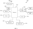
- FIG. 1 is a schematic diagram of a communications system 100 to which a method for indicating a precoding vector in an embodiment of this application is applicable.
- the communications system 100 may include at least one network device, for example, a network device 110 shown in FIG. 1 .
- the communications system 100 may further include at least one terminal device, for example, a terminal device 120 shown in FIG. 1 .
- the network device 110 and the terminal device 120 may communicate with each other through a wireless link.
- a plurality of antennas may be configured for each communications device such as the network device 110 or the terminal device 120.
- the configured plurality of antennas may include at least one transmit antenna configured to send a signal and at least one receive antenna configured to receive a signal. Therefore, communications devices in the communications system 100, for example, the network device 110 and the terminal device 120, may communicate with each other by using a multi-antenna technology.
- the network device in the communications system may be any device that has a wireless transceiver function.
- the network device includes but is not limited to an evolved NodeB (evolved NodeB, eNB), a radio network controller (radio network controller, RNC), a NodeB (NodeB, NB), a base station controller (base station controller, BSC), a base transceiver station (base transceiver station, BTS), a home NodeB (for example, a home evolved NodeB, or a home NodeB, HNB), a baseband unit (baseband unit, BBU), an access point (access point, AP) in a wireless fidelity (wireless fidelity, Wi-Fi) system, a wireless relay node, a wireless backhaul node, a transmission point (transmission point, TP), a transmission and reception point (transmission and reception point, TRP), or the like.
- eNB evolved NodeB
- RNC radio network controller
- NodeB NodeB
- the network device may be a gNB or a transmission point (TRP or TP) in a 5G system such as an NR system, may be one antenna panel or a group (including a plurality of antenna panels) of antenna panels of a base station in a 5G system, or may be a network node, such as a baseband unit (BBU) or a distributed unit (distributed unit, DU), that constitute a gNB or a transmission point.
- BBU baseband unit
- DU distributed unit
- the gNB may include a centralized unit (centralized unit, CU) and a DU.
- the gNB may further include a radio frequency unit (radio unit, RU).
- the CU implements some functions of the gNB
- the DU implements some functions of the gNB.
- the CU implements functions of a radio resource control (radio resource control, RRC) layer and a packet data convergence protocol (packet data convergence protocol, PDCP) layer
- the DU implements functions of a radio link control (radio link control, RLC) layer, a media access control (media access control, MAC) layer, and a physical (physical, PHY) layer.
- RRC radio resource control
- PDCP packet data convergence protocol
- the DU implements functions of a radio link control (radio link control, RLC) layer, a media access control (media access control, MAC) layer, and a physical (physical, PHY) layer.
- the network device may be a CU node, a DU node, or a device including a CU node and a DU node.
- the CU may be a network device in an access network (radio access network, RAN), or may be a network device in a core network (core network, CN). This is not limited in this application.
- the terminal device in the wireless communications system may also be referred to as user equipment (user equipment, UE), an access terminal, a subscriber unit, a subscriber station, a mobile station, a mobile console, a remote station, a remote terminal, a mobile device, a user terminal, a terminal, a wireless communications device, a user agent, or a user apparatus.
- user equipment user equipment
- UE user equipment
- an access terminal a subscriber unit, a subscriber station, a mobile station, a mobile console, a remote station, a remote terminal, a mobile device, a user terminal, a terminal, a wireless communications device, a user agent, or a user apparatus.
- the terminal device in the embodiments of this application may be a mobile phone (mobile phone), a tablet computer (pad), a computer with a wireless transceiver function, a virtual reality (virtual reality, VR) terminal device, an augmented reality (augmented reality, AR) terminal device, a wireless terminal in industrial control (industrial control), a wireless terminal in self driving (self driving), a wireless terminal in telemedicine (remote medical), a wireless terminal in a smart grid (smart grid), a wireless terminal in transportation safety (transportation safety), a wireless terminal in a smart city (smart city), a wireless terminal in a smart home (smart home), or the like.
- An application scenario is not limited in the embodiments of this application.
- FIG. 1 is only a simplified schematic diagram of an example for ease of understanding.
- the communications system 100 may further include another network device or another terminal device, which is not shown in FIG. 1 .
- the processing process of the downlink signal described below may be performed by the network device, or may be performed by a chip disposed in the network device.
- the network device and the chip disposed in the network device are collectively referred to as a network device below.
- the network device may process a codeword (code word) on a physical channel.
- the codeword may be a coded bit obtained through coding (for example, including channel coding).
- a codeword is scrambled (scrambling) to generate a scrambling bit.
- Modulation mapping (modulation mapping) is performed on the scrambling bit, to obtain a modulation symbol.
- the modulation symbol is mapped to a plurality of layers (layer), through layer mapping (layer mapping).
- the layer is also referred to as a transport layer.
- a modulation symbol obtained through the layer mapping is precoded (precoding), to obtain a precoded signal.
- the precoded signal is mapped to a plurality of resource elements (resource element, RE) through RE mapping. These REs are then transmitted through an antenna port (antenna port) after orthogonal multiplexing (orthogonal frequency division multiplexing, OFDM) modulation is performed on the REs.
- OFDM orthogonal multiplexing
- a network device may process a to-be-sent signal by using a precoding matrix that matches a channel resource, so that a precoded to-be-sent signal adapts to the channel, to reduce complexity of eliminating inter-channel impact by a receive device. Therefore, after the to-be-sent signal is precoded, quality (for example, a signal to interference plus noise ratio (signal to interference plus noise ratio, SINR)) of a received signal is improved. Therefore, transmission between a transmit device and a plurality of receive devices can be implemented on a same time-frequency resource by using the precoding technology. That is, multiuser multiple-input multiple-output (multiple user multiple input multiple output, MU-MIMO) is implemented.
- a precoding matrix that matches a channel resource
- SINR signal to interference plus noise ratio
- the transmit device may further perform precoding in another manner. For example, when channel information (for example, but not limited to a channel matrix) cannot be learned, precoding is performed by using a preset precoding matrix or through weighted processing. For brevity, specific content of the precoding manner is not further described in this specification.
- Precoding matrix indicator may be used to indicate a precoding matrix.
- the precoding matrix may be, for example, a precoding matrix determined by a terminal device based on a channel matrix for each subband.
- the channel matrix may be determined by the terminal device through channel estimation or the like or based on channel reciprocity.
- a specific method for determining the precoding matrix by the terminal device is not limited to the foregoing description. For a specific implementation, refer to the current technology. For brevity, details are not exhaustively described herein.
- the precoding matrix may be obtained by performing singular value decomposition (singular value decomposition, SVD) on a channel matrix or a covariance matrix of a channel matrix, or may be obtained by performing eigenvalue decomposition (eigenvalue decomposition, EVD) on a covariance matrix of a channel matrix.
- singular value decomposition singular value decomposition
- eigenvalue decomposition eigenvalue decomposition
- EVD eigenvalue decomposition
- the terminal device may quantize a precoding matrix for each subband, and may send a quantized value to the network device by using a PMI, so that the network device determines, based on the PMI, a precoding matrix that is the same as or similar to the precoding matrix determined by the terminal device.
- the network device may directly determine the precoding matrix for each subband based on the PMI, or may determine the precoding matrix for each subband based on the PMI and then perform further processing, for example, perform orthogonalization processing on precoding matrices of different users, to determine a finally used precoding matrix. Therefore, the network device can determine a precoding matrix that adapts to a channel for each subband, to perform precoding processing on a to-be-sent signal. It should be understood that for a specific method for determining, by the network device based on the PMI, the precoding matrix used for each subband, refer to the current technology. This is merely an example for ease of understanding, and should not constitute any limitation on this application.
- the precoding matrix determined by the terminal device may be understood as a to-be-fed-back precoding matrix.
- the terminal device may indicate the to-be-fed-back precoding matrix by using the PMI, so that the network device restores the precoding matrix based on the PMI. It may be understood that the precoding matrix restored by the network device based on the PMI may be the same as or similar to the to-be-fed-back precoding matrix.
- W W 1
- W represents a precoding matrix to be fed back at one transport layer, on one subband, and in two polarization directions.
- W 1 may be fed back by using a wideband
- W 2 may be fed back by using a subband.
- v 0 to v 3 are beam vectors included in W 1 , and the plurality of beam vectors may be indicated by using, for example, an index of a combination of the plurality of beam vectors.
- beam vectors in the two polarization directions are the same, and the beam vectors v 0 to v 3 are used in both of the two polarization directions.
- a 0 to a 7 are wideband amplitude coefficients included in W 1 , and may be indicated by using quantized values of the wideband amplitude coefficients.
- c 0 to c 7 are subband coefficients included in W 2 , and each subband coefficient may include a subband amplitude coefficient and a subband phase coefficient.
- c 0 to c 7 may include subband amplitude coefficients ⁇ 0 to ⁇ 7 and subband phase coefficients ⁇ 0 to ⁇ 7 , respectively, and may be indicated by using quantized values of the subband amplitude coefficients ⁇ 0 to ⁇ 7 and quantized values of the subband phase coefficients ⁇ 0 to ⁇ 7 , respectively. It can be learned that the to-be-fed-back precoding matrix may be considered as a weighted sum of the plurality of beam vectors.
- the precoding matrix shown above is obtained based on feedback at one transport layer, and therefore may also be referred to as a precoding vector.
- the terminal device may separately perform feedback based on each transport layer.
- a precoding matrix of one subband may be constructed based on a precoding vector obtained through the feedback at each transport layer. For example, if there are four transport layers, the precoding matrix may include four precoding vectors that are respectively corresponding to the four transport layers.
- feedback overheads of the terminal device As the quantity of transport layers increases, feedback overheads of the terminal device also increase. For example, when there are four transport layers, feedback overheads for a 0 to a 7 and c 0 to c 7 are at most four times those at one transport layer. In other words, if the terminal device performs the foregoing wideband feedback and subband feedback based on each transport layer, feedback overheads multiply as the quantity of transport layers increases. A larger quantity of subbands leads to a greater increase in the feedback overheads. Therefore, it is expected to provide a method that can reduce PMI feedback overheads.
- the terminal device may feed back a channel matrix to the network device by using the PMI, and the network device may determine the channel matrix based on the PMI, to determine a precoding matrix. This is not limited in this application.
- a precoding vector may be determined by a vector, for example, a column vector, in the precoding matrix.
- the precoding matrix may include one or more column vectors, and each column vector may be used to determine one precoding vector.
- the precoding matrix may also be referred to as a precoding vector.
- a precoding matrix may be determined by a precoding vector or precoding vectors at one or more transport layers, and each vector in the precoding matrix may correspond to one transport layer. It is assumed that the precoding vector may have a dimension of N 1 ⁇ 1. If a quantity of transport layers is R (R is a positive integer), the precoding matrix may have a dimension of N 1 ⁇ R. The quantity of transport layers may be indicated by using a rank indicator (rank indicator, RI), N 1 may represent a quantity of antenna ports, and N 1 is a positive integer.
- rank indicator rank indicator
- a precoding vector may alternatively be a component of a precoding matrix at one transport layer in one polarization direction. It is assumed that a quantity of polarization directions is P (P is a positive integer), and a quantity of antenna ports in one polarization direction is N2. In this case, a dimension of a precoding vector corresponding to one transport layer is (P ⁇ N 2 ) ⁇ 1, and a dimension of a precoding vector in one polarization direction may be N 2 ⁇ 1, where N 2 is a positive integer.
- the precoding vector may correspond to one transport layer, may correspond to one polarization direction at one transport layer, or may correspond to another parameter. This is not limited in this application.
- An antenna port may be referred to as a port for short.
- the antenna port may be understood as a transmit antenna identified by a receive device, or a transmit antenna that can be distinguished in space.
- One antenna port may be configured for each virtual antenna, each virtual antenna may be a weighted combination of a plurality of physical antennas, and each antenna port may correspond to one reference signal. Therefore, each antenna port may be referred to as a reference signal port, for example, a CSI-RS port or a sounding reference signal (sounding reference signal, SRS) port.
- a reference signal port for example, a CSI-RS port or a sounding reference signal (sounding reference signal, SRS) port.
- a beam may be understood as a distribution of signal strength formed in a direction in space.
- a technology of beam forming may be a beamforming (or referred to as beamforming) technology or another technology.
- the beamforming technology may be specifically a digital beamforming technology, an analog beamforming technology, or a hybrid digital/analog beamforming technology.
- a beam may be formed by using a digital beamforming technology.
- a beam vector may correspond to the beam, and may be a precoding vector in a precoding matrix, or may be a beamforming vector.
- Each element in the beam vector may represent a weight of each antenna port. Weighted signals at different antenna ports are superimposed to form an area with relatively strong signal strength.
- the beam vector may also be referred to as a spatial vector.
- a length (or a dimension) of the beam vector is a quantity of antenna ports in one polarization direction.
- the beam vector may be a column vector having a dimension of N s ⁇ 1, or may be a row vector having a dimension of 1 ⁇ N s . This is not limited in this application.
- a frequency domain unit is a unit of a frequency domain resource, and may represent different frequency domain resource granularities.
- the frequency domain unit may include, but is not limited to, a subband, a resource block (resource block, RB), a subcarrier, a resource block group (resource block group, RBG), a precoding resource block group (precoding resource block group, PRG), and the like.
- Frequency domain vector is a vector that is proposed in the embodiments of this application and that is used to indicate a change rule of a channel in frequency domain.
- the frequency domain vector may be specifically used to represent a change rule of a weighting coefficient of each beam vector on each frequency domain unit.
- This change rule may be related to a multipath delay. When a signal is transmitted on a radio channel, there may be different transmission delays on different propagation paths. Therefore, different frequency domain vectors may be used to represent a change rule of delays on different propagation paths.
- a dimension of a frequency domain vector may be a quantity of frequency domain units on which CSI measurement needs to be performed. Because quantities of frequency domain units on which CSI measurement needs to be performed may be different at different moments, a dimension of a frequency domain vector may also change. In other words, the dimension of the frequency domain vector is variable.
- a length (or the dimension) of the frequency domain vector is a quantity of frequency domain units included in a frequency domain occupation bandwidth of a CSI measurement resource.
- the frequency domain occupation bandwidth of the CSI measurement resource may be a bandwidth used to transmit a reference signal.
- the reference signal herein may be a reference signal, for example, a CSI-RS, used for channel measurement.
- the frequency domain occupation bandwidth of the CSI measurement resource may be, for example, less than or equal to a pilot transmission bandwidth (or referred to as a measurement bandwidth).
- signaling used to indicate the frequency domain occupation bandwidth of the CSI measurement resource may be, for example, a CSI-frequency occupation range (CSI-Frequency Occupation).
- the frequency domain occupation bandwidth of the CSI measurement resource is named only for ease of description, and should not constitute any limitation on this application. This application does not exclude a possibility of expressing a same meaning by using another name.
- the length of the frequency domain vector is a length of signaling used to indicate a quantity of to-be-reported frequency domain units and locations of the to-be-reported frequency domain units.
- the signaling used to indicate the quantity of the to-be-reported frequency domain units and the locations of the to-be-reported frequency domain units may be a reporting band (reporting band).
- the signaling may be used to indicate the quantity of the to-be-reported frequency domain units and the locations of the to-be-reported frequency domain units by using a bitmap. Therefore, the dimension of the frequency domain vector may be a quantity of bits in the bitmap.
- the reporting band is merely a possible name of the signaling, and should not constitute any limitation on this application. This application does not exclude a possibility of naming the signaling by using another name to implement a same or similar function.
- the length of the frequency domain vector is a quantity of to-be-reported frequency domain units.
- the quantity of to-be-reported frequency domain units may be indicated by using the foregoing signaling of reporting band.
- the quantity of to-be-reported frequency domain units may be all or some of frequency domain units in the frequency domain occupation bandwidth of the CSI measurement resource.
- the quantity of to-be-reported frequency domain units may be the same as a signaling length of the reporting band, or may be less than a signaling length of the reporting band. This is not limited in this application.
- the length of the frequency domain vector is one of the foregoing enumerated items, it may be considered that either the signaling used to indicate the frequency domain occupation bandwidth of the CSI measurement resource or signaling used to indicate the quantity of the to-be-reported frequency domain units and the locations of the to-be-reported frequency domain units is used to implicitly indicate the length of the frequency domain vector.
- indication information used for the length of the frequency domain vector is denoted as fifth indication information.
- the fifth indication information may be the signaling used to indicate the frequency domain occupation bandwidth of the CSI measurement resource, may be the signaling used to indicate the quantity of the to-be-reported frequency domain units and the locations of the to-be-reported frequency domain units, or may be signaling newly added in a future protocol. This is not limited in this application.
- the frequency domain vector may be a column vector having a dimension of N f x1, or may be a row vector having a dimension of 1 ⁇ N f . This is not limited in this application.
- Space-frequency matrix and space-frequency component matrix For ease of description, it is assumed in the following that a quantity of polarization directions of a transmit antenna is 1.
- a space-frequency matrix in the polarization direction may be constructed by using precoding vectors on different frequency domain units at one transport layer.
- the terminal device may determine a to-be-fed-back precoding matrix on each frequency domain unit through channel measurement or the like.
- the to-be-fed-back precoding matrix on each frequency domain unit is processed, to obtain a space-frequency matrix corresponding to each transport layer.
- to-be-fed-back precoding vectors on all frequency domain units may be combined to obtain a space-frequency matrix.
- the space-frequency matrix may be referred to as a to-be-fed-back space-frequency matrix.
- the terminal device may indicate the to-be-fed-back space-frequency matrix by using a weighted sum of one or more space-frequency component matrices.
- the to-be-fed-back space-frequency matrix may be approximately the weighted sum of the one or more space-frequency component matrices.
- the one or more space-frequency component matrices may be selected from a predefined space-frequency component matrix set, or may be determined based on a beam vector in a predefined beam vector set and a frequency domain vector in a predefined frequency domain vector set. This is not limited in this application.
- the space-frequency matrix may be a matrix having a dimension of N s ⁇ N f . That is, the space-frequency matrix may include N f column vectors whose lengths are N s . The N f column vectors may correspond to N f frequency domain units, and each column vector may be used to determine a precoding vector of a corresponding frequency domain unit.
- the N f column vectors may be respectively used to determine precoding vectors of the N f frequency domain units.
- the space-frequency matrix may be approximately a weighted sum of one or more space-frequency component matrices.
- one space-frequency component matrix may be uniquely determined by one beam vector and one frequency domain vector.
- one space-frequency component matrix may be a product of one beam vector and a conjugate transpose of one frequency domain vector.
- the beam vector is a column vector and the frequency domain vector is a row vector
- one space-frequency component matrix may be a product of one beam vector and one frequency domain vector. Therefore, each space-frequency component matrix may also be a matrix having a dimension of N s ⁇ N f .
- the space-frequency matrix may be a matrix having a dimension of (N s ⁇ N f ) ⁇ 1, or the space-frequency matrix may be a vector having a length of N s ⁇ N f .
- the space-frequency matrix may include only one column vector having a length of N s ⁇ N f .
- the space-frequency matrix may also be referred to as a space-frequency vector.
- H [ h 0 T h 1 T ⁇ h N f -1 T ] T .
- Vectors in the matrix have been described in detail above. For brevity, details are not described herein again.
- the space-frequency vector may be approximately a weighted sum of one or more space-frequency component vectors.
- one space-frequency component vector may be uniquely determined by one beam vector and one frequency domain vector.
- one space-frequency component vector may be a Kronecker product of one beam vector and one frequency domain vector, or may be a Kronecker product of one frequency domain vector and one beam vector. Therefore, each space-frequency component vector may also be a vector having a length of N s ⁇ N f .
- the space-frequency component matrix may also be referred to as a space-frequency component vector.
- a space-frequency vector determined by a weighted sum of a plurality of space-frequency component vectors may be obtained by sequentially connecting N f column vectors each having a length of N s .
- the N f column vectors may correspond to N f frequency domain units, and each column vector may be used to determine a precoding vector of a corresponding frequency domain unit.
- a space-frequency vector determined by a weighted sum of a plurality of space-frequency component vectors may be obtained by sequentially connecting N s column vectors each having a length of N f .
- N f elements in each column vector may correspond to N f frequency domain units.
- n f th elements in all of the N s column vectors may be sequentially connected to obtain a vector having a length of N s , and the vector may be used to determine a precoding vector of an n f th frequency domain unit. 0 ⁇ n f ⁇ N f -1, and n f is an integer.
- the space-frequency matrix may be a matrix having a dimension of 2N s ⁇ N f , or may be a vector having a length of 2N s ⁇ N f . 2 indicates that there are two polarization directions.
- the space-frequency component matrix may still be a matrix having a dimension of N s ⁇ N f or a vector having a length of N s ⁇ N f . Therefore, a space-frequency matrix in each polarization direction may be represented by a weighted sum of a plurality of space-frequency component matrices. In other words, a space-frequency matrix in each polarization direction may be approximately represented as a weighted sum of a plurality of space-frequency component matrices.
- a plurality of space-frequency component matrices used for different polarization directions may be the same, or a plurality of polarization directions may share a plurality of same space-frequency component matrices.
- space-frequency matrices or space-frequency vectors in a plurality of polarization directions at a same transport layer may be constructed by using a same group of beam vectors and a same group of frequency domain vectors.
- weighting coefficients of space-frequency component matrices in different polarization directions may be different.
- a basic unit that may be obtained by performing an operation on a beam vector and a frequency domain vector may be a space-frequency base unit, for example, a space-frequency component matrix or a space-frequency component vector.
- the space-frequency base unit may correspond to one polarization direction.
- a weighted sum of base units can be spliced to form a space-frequency matrix in a plurality of polarization directions.
- the space-frequency matrix is not limited to the foregoing examples.
- examples are not further listed one by one herein.
- the space-frequency component matrix is the product of the beam vector and the conjugate transpose of the frequency domain vector and the space-frequency component matrix is the Kronecker product of the frequency domain vector and the beam vector.
- specific processes in which the terminal device indicates a precoding vector and the network device determines a precoding vector are described in detail in the following embodiments. However, this should not constitute any limitation on this application. Based on a same concept, a person skilled in the art may perform equivalent deformation or replacement on the space-frequency component matrix. Any equivalent deformation and replacement shall fall within the protection scope of this application.
- a network device may transmit data to a terminal device by using a plurality of transport layers.
- a quantity of transport layers increases, overheads caused by feedback performed by the terminal device based on each transport layer multiply.
- a larger quantity of subbands leads to a greater increase in the feedback overheads. Therefore, it is expected to provide a method that can reduce feedback overheads.
- this application provides a method for indicating and determining a precoding vector, to reduce PMI feedback overheads.
- a quantity of polarization directions of a transmit antenna is P (P ⁇ 1 and P is an integer)
- a quantity of transport layers is R (R ⁇ 1 and R is an integer).
- numbers may be consecutive and start from 0.
- the R transport layers may include a 0 th transport layer to an (R-1) th transport layer
- the P polarization directions may include a 0 th polarization direction to a (P-1) th polarization direction.
- numbers may be consecutive and start from 1. It should be understood that the foregoing descriptions are all provided for ease of describing the technical solutions provided in the embodiments of this application, but are not intended to limit the scope of this application.
- a superscript T indicates transposition.
- a T represents a transpose of a matrix (or a vector) A.
- a superscript * represents a conjugate transpose.
- A* represents a conjugate transpose of a matrix (or a vector) A.
- a Kronecker (Kronecker) product operation of matrices is involved in the embodiments of this application.
- the Kronecker product operation may be represented by ⁇ .
- a Kronecker product of matrices A and B may be expressed as A ⁇ B .
- a Kronecker product is a block matrix obtained by multiplying all elements in a matrix by another matrix.
- projection between vectors is involved in many places.
- projecting a vector a to a vector b may be understood as calculating an inner product of the vector a and the vector b.
- used to indicate may include “used to directly indicate” and “used to indirectly indicate”.
- the indication information may be used to directly indicate I or indirectly indicate I. This does not mean that the indication information definitely carries I.
- the information indicated by the indication information is referred to as to-be-indicated information.
- the to-be-indicated information such as the to-be-indicated information itself or an index of the to-be-indicated information, may be directly indicated.
- the to-be-indicated information may be indirectly indicated by indicating other information, and there is an association relationship between the other information and the to-be-indicated information.
- only a part of the to-be-indicated information may be indicated, and the other part of the to-be-indicated information is known or agreed on in advance.
- specific information may also be indicated by using a pre-agreed (for example, stipulated in a protocol) arrangement sequence of various pieces of information, to reduce indication overheads to some extent.
- a common part of all pieces of information may be further identified and indicated in a unified manner, to reduce indication overheads caused by separately indicating same information.
- a precoding matrix is formed by precoding vectors, and each precoding vector in the precoding matrix may have a same part in terms of composition or another attribute.
- a specific indication manner may alternatively be various existing indication manners, for example, but not limited to, the foregoing indication manners and various combinations thereof.
- various indication manners refer to the current technology. Details are not further described in this specification. It can be learned from the foregoing descriptions that, for example, when a plurality of pieces of information of a same type need to be indicated, manners of indicating different information may be different.
- a required indication manner may be selected according to a specific requirement. The selected indication manner is not limited in the embodiments of this application. In this way, the indication manner involved in the embodiments of this application should be understood as covering various methods that can enable a to-be-indicated party to learn of the to-be-indicated information.
- a row vector may be represented as a column vector
- a matrix may be represented by using a transposed matrix of the matrix
- a matrix may also be represented in a form of a vector or an array, where the vector or array may be formed by connecting row vectors or column vectors of the matrix
- a Kronecker product of two vectors may also be represented in a form such as a product of a vector and a transposed vector of another vector.
- the to-be-indicated information may be sent as a whole, or may be divided into a plurality of pieces of sub-information for separate sending.
- sending periodicities and/or sending occasions of the sub-information may be the same or may be different.
- a specific sending method is not limited in this application.
- the sending periodicities and/or the sending occasions of the sub-information may be predefined, for example, predefined according to a protocol, or may be configured by a transmit end device by sending configuration information to a receive end device.
- the configuration information may include, for example, but not limited to, one of or a combination of at least two of radio resource control signaling, for example, RRC signaling, MAC layer signaling, for example, MAC-CE signaling, and physical layer signaling, for example, downlink control information (downlink control information, DCI).
- radio resource control signaling for example, RRC signaling
- MAC layer signaling for example, MAC-CE signaling
- physical layer signaling for example, downlink control information (downlink control information, DCI).
- sequence numbers are merely used for differentiation for ease of description, and are not used to limit the scope of the embodiments of this application.
- sequence numbers are used to distinguish between different indication information or different transport layers.
- "obtained in advance” may include being indicated by signaling of the network device or being predefined, for example, defined in a protocol.
- the foregoing “predefinition” may be implemented by prestoring corresponding code or a corresponding table in a device (for example, including the terminal device and the network device) or in another manner that can be used to indicate related information.
- a specific implementation of the foregoing “predefinition” is not limited in this application.
- Tenth, storage involved in the embodiments of this application may be storage in one or more memories.
- the one or more memories may be separately disposed, or may be integrated into an encoder or a decoder, a processor, or a communications apparatus.
- a part of the one or more memories may be separately disposed, and a part of the one or more memories are integrated into a decoder, a processor, or a communications apparatus.
- the memory may be a storage medium in any form. This is not limited in this application.
- the "protocol” involved in the embodiments of this application may be a standard protocol in the communications field, for example, may include an LTE protocol, an NR protocol, and a related protocol applied to a future communications system. This is not limited in this application.
- At least one of a, b, and c may represent: a, b, c, a and b, a and c, b and c, or a, b, and c.
- a, b, and c each may be singular or plural.
- the communications system may include at least one network device and at least one terminal device.
- the network device and the terminal device may communicate with each other by using a multi-antenna technology.
- an execution body of the method provided in the embodiments of this application is not particularly limited in the following embodiments, provided that a program that records code of the method provided in the embodiments of this application can be run to perform communication according to the method provided in the embodiments of this application.
- the execution body of the method provided in the embodiments of this application may be the terminal device or the network device, or a functional module that is in the terminal device or the network device and that can invoke and execute the program.
- FIG. 2 is a schematic flowchart of a method 200, from a perspective of device interaction, for indicating and determining a precoding vector according to an embodiment of this application.
- the method 200 may include step 210 to step 230. The following describes each step in the method 200 in detail.
- a terminal device indicates a precoding vector based on one of one or more transport layers and one of one or more polarization directions at the transport layer, and a network device determines the precoding vector is first described in detail.
- a quantity of transport layers and a quantity of polarization directions of a transmit antenna are not limited in this application.
- one transport layer may be any one of one or more transport layers
- one polarization direction may be any one of one or more polarization directions.
- the terminal device In step 210, the terminal device generates first indication information, where the first indication information is used to indicate L 1 (L 1 ⁇ 1 and L 1 is an integer) beam vectors in a beam vector set, K 1 (K 1 ⁇ 1 and K 1 is an integer) frequency domain vectors in a frequency domain vector set, and T 1 (T 1 ⁇ 1 and T 1 is an integer) space-frequency component matrices in L 1 ⁇ K 1 space-frequency component matrices corresponding to the L 1 beam vectors and the K 1 frequency domain vectors.
- the T 1 space-frequency component matrices may be a subset of the M 1 space-frequency component matrices.
- the M 1 space-frequency component matrices herein may be obtained by separately traversing the L 1 beam vectors and the K 1 frequency domain vectors.
- the selected L 1 beam vectors in the beam vector set are denoted as ⁇ s 0 , ⁇ s 1 , ..., and ⁇ s L 1 ⁇ 1
- the selected K 1 frequency domain vectors in the frequency domain vector set are denoted as ⁇ f 0 , ⁇ f 1 , ..., and ⁇ f K 1 ⁇ 1 .
- the terminal device may first traverse all beam vectors in a range from 0 to L 1 -1, and then traverse all frequency domain vectors in a range from 0 to K 1 -1, to obtain the M 1 space-frequency component matrices.
- the M 1 space-frequency component matrices may include ⁇ s 0 ⁇ f 0 ⁇ , ⁇ s 1 ⁇ f 0 ⁇ , ..., ⁇ s L 1 ⁇ 1 ⁇ f 0 ⁇ , ⁇ s 0 ⁇ f 1 ⁇ , ⁇ s 1 ⁇ f 1 ⁇ , ..., ⁇ s L 1 ⁇ 1 ⁇ f 1 ⁇ , ..., ⁇ s 0 ⁇ f K 1 ⁇ 1 ⁇ , ⁇ s 1 ⁇ f K 1 ⁇ 1 ⁇ , ..., and ⁇ s L 1 ⁇ 1 ⁇ f K 1 ⁇ 1 ⁇ .
- the terminal device may first traverse all frequency domain vectors in a range from 0 to K 1 -1, and then traverse all beam vectors in a range from 0 to L 1 -1, to obtain the M 1 space-frequency component matrices.
- the M 1 space-frequency component matrices may include ⁇ s 0 ⁇ f 0 ⁇ , ⁇ s 0 ⁇ f 1 ⁇ , ..., ⁇ s 0 ⁇ f K 1 ⁇ 1 ⁇ , ⁇ s 1 ⁇ f 0 ⁇ , ⁇ s 1 ⁇ f 1 ⁇ , ..., ⁇ s 1 ⁇ f K 1 ⁇ 1 ⁇ , ... , ⁇ s L 1 ⁇ 1 ⁇ f 0 ⁇ , ⁇ s L 1 ⁇ 1 ⁇ f 1 ⁇ , ..., and ⁇ s L 1 ⁇ 1 ⁇ f K 1 ⁇ 1 ⁇ .
- the M 1 space-frequency component matrices may alternatively be obtained by using a Kronecker product of a frequency domain vector and a beam vector.
- the first indication information may be used to indicate relative locations (for example, relative indexes or relative numbers) of the T 1 space-frequency component matrices in the M 1 space-frequency component matrices.
- the terminal device may indicate the T 1 space-frequency component matrices by using a bitmap, an index of a combination of the T 1 space-frequency component matrices in the M 1 space-frequency component matrices, an index of each of the T 1 space-frequency component matrices in the M 1 space-frequency component matrices, or the like.
- the terminal device indicates the T 1 space-frequency component matrices by using a bitmap
- M 1 bits may be used as relative locations of the T 1 space-frequency component matrices in the M 1 space-frequency component matrices.
- the terminal device may further indicate the L 1 beam vectors by using ⁇ log 2 C L 0 L 1 ⁇ bits, and indicate the K 1 frequency domain vectors by using ⁇ log 2 C K 0 K 1 ⁇ bits. Therefore, the terminal device may indicate the T 1 space-frequency component matrices by using ⁇ log 2 C L 0 L 1 ⁇ + ⁇ log 2 C K 0 K 1 ⁇ + M 1 bits.
- the beam vector set includes L 0 beam vectors
- the frequency domain vector set includes K 0 frequency domain vectors, where L 0 ⁇ L 1 , K 0 ⁇ K 1 , and L 0 ⁇ K 0 >L 1 ⁇ K 1 .
- the L 0 beam vectors and the K 0 frequency domain vectors may correspond to L 0 ⁇ K 0 space-frequency component matrices.
- ⁇ log 2 L 0 ⁇ + ⁇ log 2 K 0 ⁇ bits may be required if each space-frequency component matrix is separately indicated. If a bitmap is used for indication, L 0 ⁇ K 0 bits may be used.
- the beam vector set includes 16 beam vectors
- the frequency domain vector set includes 10 frequency domain vectors
- 15 space-frequency vector matrices are selected from 160 space-frequency component matrices constructed by using the beam vector set and the frequency domain vector set.
- each space-frequency component matrix is separately indicated, ⁇ log 2 16 ⁇ + ⁇ log 2 10 ⁇ bits, that is, 8 bits, are required for each space-frequency vector matrix, and 120 bits are required for feedback of the 15 space-frequency vector matrices. If the 15 space-frequency component matrices are indicated by using a bitmap, 160 bits are required for feedback.
- the terminal device and the network device may need to prestore a large quantity of one-to-one correspondences between combinations and indexes.
- a part of relatively strong beam vectors and a part of relatively strong frequency domain vectors may be first indicated in the 16 beam vectors and the 10 frequency domain vectors, and then 15 space-frequency component matrices may be selected from the part of relatively strong beam vectors and the part of relatively strong frequency domain vectors.
- the eight beam vectors and the five frequency domain vectors may be fed back by using ⁇ log 2 C 16 8 ⁇ bits and ⁇ log 2 C 10 5 ⁇ bits respectively, that is, 14 bits and 8 bits respectively.
- the terminal device may further indicate the selected 15 space-frequency component matrices. If the terminal device indicates the 15 space-frequency component matrices by using a bitmap, 40 bits may be used for indication. In this case, the 15 space-frequency component matrices may be fed back by using 62 bits. Compared with the foregoing manner, this manner can greatly reduce overheads.
- a weighted sum of the T 1 space-frequency component matrices may be used to determine a precoding vector of one or more frequency domain units.
- the weighted sum of the T 1 space-frequency component matrices may be used to construct a space-frequency matrix.
- the space-frequency matrix may include one or more column vectors corresponding to the one or more frequency domain units, and each column vector may be used to determine a precoding vector of a corresponding frequency domain unit.
- the space-frequency matrix may be approximately the weighted sum of the T 1 space-frequency component matrices.
- U t 1 represents a t 1 th space-frequency component matrix in the T 1 space-frequency component matrices, and a t 1 represents a weighting coefficient of the t 1 th space-frequency component matrix U t 1 .
- the terminal device may predetermine the T 1 space-frequency component matrices, or may predetermine space-frequency vector pairs used to generate the T 1 space-frequency component matrices, and then may further determine weights of the T 1 space-frequency component matrices or the T 1 space-frequency vector pairs.
- the terminal device may indicate the T 1 space-frequency component matrices and the weights of the space-frequency component matrices to the network device, or indicate the T 1 space-frequency vector pairs and the weights of the space-frequency vector pairs to the terminal device, so that the network device restores the precoding vector of the one or more frequency domain units.
- the T 1 space-frequency component matrices indicated by the first indication information may be used to determine the precoding vector with reference to the weights of the space-frequency component matrices.
- the weights of the space-frequency component matrices each may be indicated by using the first indication information, or may be indicated by using other information. This is not limited in this application. For a specific method for indicating a weight of each space-frequency component matrix, refer to the current technology.
- each of the T 1 space-frequency component matrices may be uniquely determined by one beam vector and one frequency domain vector in the T 1 space-frequency vector pairs. Therefore, the terminal device may directly indicate the T 1 space-frequency component matrices, may indirectly indicate the T 1 space-frequency component matrices by indicating the T 1 space-frequency vector pairs, or may directly indicate the T 1 space-frequency vector pairs.
- the T 1 space-frequency vector pairs may be considered as an equivalent form of the T 1 space-frequency component matrices.
- the T 1 space-frequency component matrices are selected from the M 1 space-frequency component matrices corresponding to the L 1 beam vectors and the K 1 frequency domain vectors.
- the T 1 space-frequency component matrices may be determined based on the L 1 beam vectors in the beam vector set and the K 1 frequency domain vectors in the frequency domain vector set.
- the terminal device may indicate the T 1 space-frequency component matrices based on the L 1 beam vectors and the K 1 frequency domain vectors.
- the T 1 space-frequency vector pairs may be selected from M 1 space-frequency vector pairs obtained by combining the L 1 beam vectors and the K 1 frequency domain vectors.
- the T 1 space-frequency vector pairs may be selected from the M 1 space-frequency vector pairs obtained by combining the L 1 beam vectors in the beam vector set and the K 1 frequency domain vectors in the frequency domain vector set.
- the T 1 space-frequency vector pairs may be a part of space-frequency vector pairs in the M 1 space-frequency vector pairs.
- the terminal device may indicate the T 1 space-frequency vector pairs based on the L 1 beam vectors and the K 1 frequency domain vectors, or based on the M 1 space-frequency vector pairs.
- the L 1 beam vectors may be a part of beam vectors in the beam vector set, and/or the K 1 frequency domain vectors may be a part of frequency domain vectors in the frequency domain vector set.
- the K 1 frequency domain vectors are only a part of frequency domain vectors in the frequency domain vector set; when the K 1 frequency domain vectors are all frequency domain vectors in the frequency domain vector set, the L 1 beam vectors are only a part of beam vectors in the beam vector set; when the L 1 beam vectors are a part of beam vectors in the beam vector set, the K 1 frequency domain vectors may be a part or all of frequency domain vectors in the frequency domain vector set; when the K 1 frequency domain vectors are a part of frequency domain vectors in the frequency domain vector set, the L 1 beam vectors may be a part or all of beam vectors in the beam vector set.
- the beam vector set includes L 0 beam vectors
- the frequency domain vector set includes K 0 frequency domain vectors.
- the L 1 beam vectors When the L 1 beam vectors are a part of beam vectors in the beam vector set, the L 1 beam vectors may be L 1 relatively strong beam vectors selected from the beam vector set.
- the K 1 frequency domain vectors When the K 1 frequency domain vectors are a part of frequency domain vectors in the frequency domain vector set, the K 1 frequency domain vectors may be K 1 relatively strong frequency domain vectors selected from the frequency domain vector set.
- the L 1 relatively strong beam vectors may be understood as L beam vectors with relatively large weighting coefficients, and the K 1 relatively strong frequency domain vectors may be understood as K 1 beam vectors with relatively large weighting coefficients.
- the terminal device may pre-determine the L 1 beam vectors in the beam vector set and the K 1 frequency domain vectors in the frequency domain vector set, narrow a selection range of the T 1 space-frequency component matrices used for weighted summation to a range of the M 1 space-frequency component matrices constructed by using the L 1 beam vectors and the K 1 frequency domain vectors, select the T 1 space-frequency component matrices from the M 1 space-frequency component matrices, and indicate the T 1 space-frequency component, thereby helping reduce feedback overheads of the T 1 space-frequency component matrices.
- the terminal device may obtain the M 1 space-frequency vector pairs by combining the L 1 beam vectors and the K 1 frequency domain vectors.
- the M 1 space-frequency component matrices may be constructed by using the L 1 beam vectors and the K 1 frequency domain vectors, or by using the M 1 space-frequency vector pairs. In other words, the M 1 space-frequency vector pairs and the M 1 space-frequency component matrices may be mutually converted.
- the M 1 space-frequency component matrices correspond to the L 1 beam vectors and the K 1 frequency domain vectors.
- M 1 is introduced only to reflect a correspondence between the M 1 space-frequency component matrices (space-frequency component vectors or space-frequency vector pairs) and the L 1 beam vectors and between the M 1 space-frequency component matrices and the K 1 frequency domain vectors, and should not constitute any limitation on this application.
- Values of L 1 , K 1 , and T 1 may be indicated by the network device, or may be predefined, for example, may be defined in a protocol, or may be determined by the terminal device and then reported to the network device, or may be configured by combining the foregoing enumerated methods.
- the method further includes: The terminal device receives second indication information, where the second indication information is used to indicate values of at least two of L 1 , K 1 , and M 1 .
- the network device sends the second indication information.
- the second indication information is carried in higher layer signaling, for example, an RRC message.
- the method further includes: The terminal device sends second indication information, where the second indication information is used to indicate a value or values of one or more of L 1 , K 1 , and M 1 .
- the network device receives the second indication information.
- the second indication information is carried in uplink control information (uplink control information, UCI), for example, CSI.
- uplink control information uplink control information, UCI
- CSI uplink control information
- information used to indicate the values of L 1 , K 1 , and M 1 may be same information, or may be different information. This is not limited in this application.
- the value of either L 1 or K 1 may be predefined, for example, defined in a protocol, and the value of the other one of L 1 or K 1 is indicated by the network device by using signaling.
- the value of L 1 may be indicated by the network device by using signaling, and the value of K 1 may be defined in a protocol.
- the value of K 1 is not limited in this application.
- the value of L 1 may be indicated by the network device by using signaling, and a calculation formula of K 1 or that the value of K 1 is a value of a parameter may be defined in a protocol.
- the value of K 1 is implicitly indicated by using the fifth indication information.
- ⁇ ⁇ indicates rounding up
- ⁇ ⁇ indicates rounding down
- [ ] indicates rounding off.
- the value of K 1 may be indicated by the network device by using signaling, and the value of L 1 may be defined in a protocol.
- the value of L 1 is not limited in this application.
- the value of K 1 may be indicated by the network device by using signaling, and the value of L 1 being a value of a parameter or a calculation formula of L 1 may be defined in a protocol.
- the value of L 1 may be understood as being implicitly indicated by using indication information used to indicate a quantity of antenna ports in a single polarization direction.
- the value of either L 1 or K 1 may be predefined, for example, defined in a protocol, and the value of the other one of L 1 and K 1 is determined by the terminal device and reported by the terminal device by using signaling.
- the second indication information may be used to indicate a value of the other one of L 1 and K 1 .
- the value of K 1 is defined in the protocol, and the second indication information is used to indicate only the value of L 1 .
- the value of L 1 is defined in the protocol, and the second indication information is used to indicate only the value of K 1 .
- the second indication information may also be used to indirectly indicate the value of L 1 by indicating a value of M 1 .
- the second indication information may also be used to indirectly indicate the value of K 1 by indicating a value of M 1 .
- the method further includes: The terminal device receives third indication information, where the third indication information is used to indicate the value of T 1 .
- the network device sends the third indication information.
- the third indication information is carried in higher layer signaling, for example, an RRC message.
- the method further includes: The terminal device sends third indication information, where the third indication information is used to indicate the value of T 1 .
- the network device receives the third indication information.
- the third indication information is carried in UCI, for example, CSI.
- the foregoing enumerated signaling used for the third indication information is merely an example, and should not constitute any limitation on this application. Specific signaling that carries the third indication information is not limited in this application.
- the second indication information and the third indication information may be same information, or may be different information. This is not limited in this application.
- the terminal device may determine the L 1 beam vectors, the K 1 frequency domain vectors, and the T 1 space-frequency component matrices, to generate the first indication information.
- the first indication information is used to indicate L 1 beam vectors and T 1 space-frequency component matrices, and a weighted sum of the T 1 space-frequency component matrices is used to determine a precoding vector of one or more frequency domain units.
- the L 1 beam vectors and K 1 frequency domain vectors correspond to M 1 space-frequency component matrices
- the T 1 space-frequency component matrices are a part of the M 1 space-frequency component matrices
- each of the M 1 space-frequency component matrices is uniquely determined by one of the L 1 beam vectors and one of the K 1 frequency domain vectors
- M 1 L 1 ⁇ K 1
- the L 1 beam vectors are a part of beam vectors in the beam vector set
- the K 1 frequency domain vectors are a part of frequency domain vectors in the frequency domain vector set
- M 1 , L 1 , K 1 , and T 1 are all positive integers.
- the K 1 frequency domain vectors are preconfigured.
- the K 1 frequency domain vectors may be all or a part of frequency domain vectors in the frequency domain vector set.
- the value of K 1 may be predefined in the protocol, and frequency domain vectors in the frequency domain vector set that are used as the K 1 frequency domain vectors may be specified in advance.
- the value of K 1 may be predefined in the protocol, and the K 1 frequency domain vectors may be indicated by the network device in advance by using signaling.
- the K 1 frequency domain vectors may be specified in advance, for example, defined in a protocol or configured by the network device. This is not limited in this application.
- the terminal device may also be predefined in the protocol that the terminal device determines, based on different values of parameters, a vector that needs to be reported.
- the L 1 beam vectors may be a universal set of the beam vector set, or the K 1 frequency domain vectors may be a universal set of the frequency domain vector set.
- the terminal device may determine, based on the values of L 1 and K 1 , whether to select the universal set of the beam vector set or the universal set of the frequency domain vector set. When the L 1 beam vectors are the universal set of the beam vector set, the terminal device may not report the L 1 beam vectors. When the K 1 frequency domain vectors are the universal set of the frequency domain vector set, the terminal device may not report the K 1 frequency domain vectors.
- the network device may configure the value of K 1 by using signaling, for example, the second indication information.
- the terminal device may use the universal set of the frequency domain vector set as the K 1 frequency domain vectors by default.
- the network device may not indicate the value of K 1 by using additional signaling.
- only the value of L 1 is indicated in the second indication information.
- the second indication information is used to indicate the value of L 1 . This may be understood as that the network device implicitly indicates, by using the second indication information, that the value of K 1 is K 0 .
- the value of K 1 may be defined in a protocol as a fixed value.
- the terminal device may use the universal set of the frequency domain vector set as the K 1 frequency domain vectors by default, and does not need to report the K 1 frequency domain vectors.
- the network device may configure the value of L 1 by using signaling, for example, the second indication information.
- the terminal device may use the universal set of the beam vector set as the L 1 beam vectors by default.
- the network device may not indicate the value of L 1 by using additional signaling.
- only the value of K 1 is indicated in the second indication information.
- the second indication information is used to indicate the value of K 1 . In this case, this may be understood as that the network device implicitly indicates, by using the second indication information, that the value of L 1 is L 0 .
- the value of L 1 may be defined in a protocol as a fixed value.
- the terminal device may use the universal set of the beam vector set as the L 1 beam vectors by default, and does not need to report the L 1 beam vectors.
- the terminal device may determine, based on a parameter configured by the network device, a vector that needs to be reported.
- a parameter configured by the network device it may alternatively be predefined in the protocol that the terminal device determines, based on different parameters configured by the network device, a vector that needs to be reported.
- all L 0 beam vectors in the beam vector set may be used as the L 1 beam vectors.
- the terminal device may report only the K 1 frequency domain vectors and the T 1 space-frequency vector pairs. If the network device indicates the values of L 1 and K 1 by using signaling, the terminal device may directly perform weighted summation on the L 1 beam vectors and the K 1 frequency domain vectors by default, may report only the L 1 beam vectors and the K 1 frequency domain vectors, and does not need to report the T 1 space-frequency vector pairs.
- the following uses an example in which L 1 ⁇ L 0 and K 1 ⁇ K 0 to describe in detail a specific method for determining and indicating, by the terminal device, the T 1 space-frequency component matrices and the weights of the space-frequency component matrices.
- the terminal device may determine the T 1 space-frequency component matrices in a corresponding implementation based on a prestored vector set. For example, the terminal device may prestore a beam vector set and a frequency domain vector set, and determine the T 1 space-frequency vector pairs based on Implementation 1. Alternatively, the terminal device may prestore a space-frequency component matrix set, and determine the T 1 space-frequency component matrices based on Implementation 2.
- the beam vector set and the frequency domain vector set may be converted into the space-frequency component matrix set, or vice versa. Any beam vector in the beam vector set and any frequency domain vector in the frequency domain vector set may be used to obtain one space-frequency component matrix in the space-frequency component matrix set. Any space-frequency component matrix in the space-frequency component matrix set may be uniquely determined by one beam vector in the beam vector set and one frequency domain vector in the frequency domain vector set.
- an index corresponding to each space-frequency vector matrix in the space-frequency vector matrix set may also be converted into an index of a beam vector in the beam vector set and an index of a frequency domain vector in the frequency domain vector set.
- any space-frequency component vector matrix in the space-frequency vector matrix set may be indicated jointly by using one beam vector in the beam vector set and one frequency domain vector in the frequency domain vector set.
- the terminal device may indicate the T 1 space-frequency component matrices by using at least the L 1 beam vectors in the beam vector set and the K 1 frequency domain vectors in the frequency domain vector set in either of the following implementations:
- the T 1 space-frequency component matrices may be determined by M 1 space-frequency vector pairs, and the M 1 space-frequency vector pairs may be obtained by combining the L 1 beam vectors and the K 1 frequency domain vectors.
- the terminal device may indicate, in the M 1 space-frequency vector pairs, T 1 space-frequency vector pairs used to generate the T 1 space-frequency component matrices.
- the T 1 space-frequency component matrices may be selected from M 1 space-frequency component matrices, and the M 1 space-frequency component matrices may be determined by the L 1 beam vectors and the K 1 frequency domain vectors.
- the terminal device may indicate the T 1 space-frequency component matrices in the M 1 space-frequency component matrices. It should be noted that manners of prestoring a vector set or a matrix set by the terminal device and the network device are not limited in this application. For example, both the terminal device and the network device may prestore the beam vector set and the frequency domain vector set. Alternatively, both the terminal device and the network device may prestore the space-frequency component matrix set.
- the terminal device may prestore the beam vector set and the frequency domain vector set, and the network device may prestore the space-frequency component matrix set.
- the terminal device may prestore the space-frequency component matrix set, and the network device may prestore the beam vector set and the frequency domain vector set.
- the beam vector set and the frequency domain vector set may be converted into the space-frequency component matrix set, or vice versa, when the space-frequency component matrix set and the beam vector matrix are determined, the frequency domain vector set may be deduced; or when the space-frequency component matrix set and the frequency domain vector set are determined, the beam vector set may be deduced. Therefore, specific forms of the vector set prestored by the terminal device and the network device are not limited in this application.
- the terminal device may determine the M 1 space-frequency vector pairs based on a prestored beam vector set, a prestored frequency domain vector set, and a predetermined space-frequency matrix, to determine the T 1 space-frequency component matrices.
- precoding vectors of N f frequency domain units determined by the terminal device are denoted as h 0 , h 1,... , and h N f -1 .
- the precoding vectors of the N f frequency domain units may be used to construct a space-frequency matrix H, where H ⁇ h 0 h 1 ⁇ h N f ⁇ 1 , or H ⁇ h 0 T h 1 T ⁇ h N f ⁇ 1 T T .
- the terminal device may construct, based on the precoding vectors of the N f frequency domain units, the space-frequency matrix H having a dimension of N s ⁇ N f , where H ⁇ h 0 h 1 ⁇ h N f ⁇ 1 .
- a dimension of each beam vector may be N s , and each beam vector may be obtained from a two-dimensional (2 dimension, 2D)-DFT matrix. 2D may represent two different directions, for example, a horizontal direction and a vertical direction.
- the N s beam vectors may be denoted as b s,0 , b s,1 ,..., and b s, N s -1 .
- a matrix B s may be constructed by using the L 0 beam vectors, where B s ⁇ b s , 0 b s , 1 ⁇ b s , N s ⁇ 1 .
- a beam vector set may be extended to O s ⁇ N s beam vectors by using an oversampling factor O s .
- a dimension of each beam vector in the beam vector set may be N s , and each beam vector may be obtained from an oversampled 2D-DFT matrix.
- N s beam vectors in an o s th (0 ⁇ o s ⁇ O s -1, and o s is an integer) subset of the beam vector set may be denoted as b s , 0 o s , b s , 1 o s , ..., and b s , N s ⁇ 1 o s .
- a matrix B s o s may be constructed based on the N s beam vectors in the o s th subset, where B s o s ⁇ b s , 0 o s b s , 1 o s ⁇ b s , N s ⁇ 1 o s .
- a dimension of each frequency domain vector may be N f , and each frequency domain vector may be obtained from a DFT matrix.
- the N f frequency domain vectors may be denoted as b f,0 , b f,1 , ..., and b f, Nf-1 .
- a matrix B f may be constructed based on the N f frequency domain vectors, where B f ⁇ b f ,0 b f , 1 ⁇ b f , N f ⁇ 1 .
- a frequency domain vector set may be extended to O f ⁇ N f frequency domain vectors by using an oversampling factor Of.
- a dimension of each frequency domain vector in the frequency domain vector set may be N f , and each frequency domain vector may be obtained from an oversampled DFT matrix.
- the oversampling factor Of is a positive integer.
- N f frequency domain vectors in an o f th (0 ⁇ o f ⁇ O f -1, and o s is an integer) subset in the frequency domain vector set may be denoted as B f ,0 o f , b f ,1 o f , ..., and b f , N f ⁇ 1 o f .
- a matrix B f o f may be constructed based on the N s beam vectors in the o f th subset, where B f o f ⁇ b f , 0 o f b f , 1 o f ⁇ b f , N f ⁇ 1 o f .
- the terminal device may determine the T 1 space-frequency component matrices and the weighting coefficients of the space-frequency component matrices by using step 1-i to step 1-v shown below.
- Step 1-i The terminal device may determine a weighting coefficient matrix based on the space-frequency matrix H, a matrix constructed based on the beam vector set, and a matrix constructed based on the frequency domain vector set.
- the beam vector set may include N s beam vectors, and the constructed matrix is B s ; the frequency domain vector set may include N f frequency domain vectors, and a constructed matrix is B f .
- the matrix W may be referred to as a weighting coefficient matrix, and a dimension of the weighting coefficient matrix may be N s ⁇ N f .
- N s rows in the matrix W may correspond to the N s beam vectors in the beam vector set (or the matrix B s constructed by using the beam vector set).
- N f columns in the matrix W may correspond to the N f frequency domain vectors in the frequency domain vector set (or the matrix B f constructed based on the frequency domain vector set).
- Each coefficient in the matrix may correspond to one space-frequency vector pair.
- Step 1-ii The terminal device may select L 1 relatively strong beam vectors from the beam vector set, and select K 1 relatively strong frequency domain vectors from the frequency domain vector set.
- the terminal device may separately perform modulo operations on the N s rows in the matrix W, and determine L 1 rows with relatively large moduli according to a modulus of each row.
- Row numbers of the L 1 rows in the matrix W may be sequence numbers of the L 1 relatively strong beam vectors in the beam vector set or column numbers of the L 1 relatively strong beam vectors in B s .
- the terminal device may separately perform modulo operations on the N f columns in the matrix W, and determine K 1 columns with relatively large moduli according to a modulus of each column.
- the column numbers of the K 1 columns in the matrix W may be sequence numbers of the K 1 relatively strong frequency domain vectors in the frequency domain vector set or column numbers of the K 1 relatively strong frequency domain vectors in B f .
- the foregoing method for determining the L 1 beam vectors and the K 1 frequency domain vectors by using the weighting coefficient matrix is merely a possible implementation shown for ease of understanding, but this does not indicate that the terminal device definitely generates the weighting coefficient matrix when determining the L 1 beam vectors and the K 1 frequency domain vectors.
- a precoding vector of each frequency domain unit is separately projected to each beam vector in the beam vector set and each frequency domain vector in the frequency domain vector set, to obtain an array set including a plurality of projection values. Elements in the array set may be obtained by sequentially connecting elements in rows (or columns) in the foregoing weighting coefficient matrix.
- Step 1-iii The terminal device may obtain M 1 space-frequency vector pairs by combining the L 1 relatively strong beam vectors determined in the beam vector set and the K 1 relatively strong frequency domain vectors determined in the frequency domain vector set.
- Each of the M 1 space-frequency vector pairs may include one beam vector and one frequency domain vector.
- the beam vector in each space-frequency vector pair may be obtained from the foregoing L 1 beam vectors, and the frequency domain vector in each space-frequency vector pair may be obtained from the foregoing K 1 frequency domain vectors.
- One of the L 1 beam vectors and one of the K 1 frequency domain vectors may be combined to obtain a unique space-frequency vector pair.
- the N s beam vectors in the beam vector set and the N f frequency domain vectors in the frequency domain vector set may be combined to obtain N s ⁇ N f space-frequency vector pairs. Therefore, the M 1 space-frequency vector pairs may be considered as a subset of the N s ⁇ N f space-frequency vector pairs, and M 1 ⁇ N s ⁇ N f .
- the terminal device may determine, in a subset of a space-frequency vector pair set that is obtained by combining the beam vector set and the frequency domain vector set, T 1 space-frequency vector pairs whose space frequency is used for linear weighting, that is, T 1 space-frequency vector pairs that need to be reported by the terminal device.
- the selected T 1 space-frequency vector pairs are selected from the M 1 space-frequency vector pairs obtained by combining the L 1 beam vectors and the K 1 frequency domain vectors.
- Step 1-iv The terminal device may determine the T 1 space-frequency vector pairs in the M 1 space-frequency vector pairs.
- the T 1 space-frequency vector pairs may be used to determine the T 1 space-frequency component matrices.
- the terminal device may select T 1 relatively strong space-frequency vector pairs from the M 1 space-frequency vector pairs, to generate the T 1 space-frequency component matrices.
- the T 1 relatively strong space-frequency vector pairs may be space-frequency vector pairs whose weighting coefficients have relatively large moduli in the M 1 space-frequency vector pairs. That is, a modulus of a weighting coefficient of any one of the selected T 1 space-frequency vector pairs is greater than or equal to a modulus of a weighting coefficient of any one of remaining M 1 -T 1 space-frequency vector pairs.
- the terminal device may determine L 1 ⁇ K 1 (that is, M 1 ) weighting coefficients.
- the M 1 weighting coefficients may be in a one-to-one correspondence with the M 1 space-frequency vector pairs.
- the terminal device may determine T 1 weighting coefficients with relatively larger moduli in the M 1 weighting coefficients. A modulus of any one of the selected T 1 weighting coefficients is greater than or equal to a modulus of any one of remaining M 1 -T 1 weighting coefficients.
- the T 1 weighting coefficients may be weighting coefficients of the T 1 space-frequency component matrices.
- Locations of the T 1 weighting coefficients in the L 1 ⁇ K 1 weighting coefficients may be used to determine T 1 beam vectors and T 1 frequency domain vectors included in the T 1 space-frequency vector pairs.
- the terminal device may extract, from the matrix W, the L 1 rows with relatively large moduli and the K 1 columns with relatively large moduli, to obtain a matrix having a dimension of L 1 ⁇ K 1 .
- the matrix having the dimension of L 1 ⁇ K 1 is denoted as W '.
- the matrix W ' may be considered as a submatrix of the matrix W.
- the terminal device may perform a modulo operation on each element in the matrix W ', to select T 1 elements with relatively large moduli.
- Locations of the T 1 elements in the matrix W ' may be used to determine locations, in the L 1 beam vectors, of the beam vectors included in the T 1 space-frequency vector pairs and locations, in the K 1 frequency domain vectors, of the frequency domain vectors included in the T 1 space-frequency vector pairs.
- row numbers of the T 1 elements in the matrix W' may be sequence numbers of the selected T 1 beam vectors in the L 1 beam vectors
- column numbers of the T 1 elements in the matrix W ' may be sequence numbers of the selected T 1 frequency domain vectors in the K 1 frequency domain vectors.
- the terminal device may sequentially arrange the L 1 rows with relatively large moduli and the K 1 columns with relatively large moduli that are extracted from the matrix W, to obtain an array including the L 1 ⁇ K 1 weighting coefficients.
- the terminal device may perform a modulo operation on each element in the array, to select T 1 elements with relatively large moduli. Locations of the T 1 elements in the array may be used to determine locations, in the L 1 beam vectors, of the beam vectors included in the T 1 space-frequency vector pairs and locations, in the K 1 frequency domain vectors, of the frequency domain vectors included in the T 1 space-frequency vector pairs.
- the T 1 space-frequency vector pairs may be used to determine the T 1 space-frequency component matrices. It is assumed that the T 1 beam vectors in the T 1 space-frequency vector pairs selected by the terminal device in step 1-iv are denoted as u s 0 , u s 1 , ..., and u s T 1 ⁇ 1 , and that the T 1 frequency domain vectors in the T 1 space-frequency vector pairs are denoted as u f 0 , u f 1 , ..., and u f T 1 ⁇ 1 .
- u s t 1 u f t 1 ⁇ may be a matrix having a dimension of N s ⁇ N f
- u f t 1 ⁇ u s t 1 may be a vector having a length of N s ⁇ N f .
- the terminal device does not necessarily generate the T 1 space-frequency component matrices based on the T 1 space-frequency vector pairs described above.
- T 1 space-frequency component matrices based on the T 1 space-frequency vector pairs described above.
- Step 1-v The terminal device generates the first indication information, to indicate the L 1 beam vectors, the K 1 frequency domain vectors, and the T 1 space-frequency vector pairs.
- the first indication information may include location information of the L 1 beam vectors in the beam vector set, location information of the K 1 frequency domain vectors in the frequency domain vector set, and information used to indicate the T 1 space-frequency vector pairs.
- the first indication information when used to indicate the L 1 beam vectors, the first indication information may be used to indicate an index of a combination of the L 1 beam vectors in the beam vector set.
- a plurality of combinations of a plurality of beam vectors may be predefined in a protocol, and each combination may correspond to one index.
- the L 1 beam vectors may be one of the plurality of combinations, or close to one of the plurality of combinations.
- the first indication information may indicate the L 1 beam vectors by indicating an index of the combination.
- the location information of the L 1 beam vectors in the beam vector set may be an index of a combination of the L 1 beam vectors in the beam vector set.
- the terminal device may indicate the L 1 beam vectors in the beam vector set by using log 2 ⁇ C N s L 1 ⁇ bits. ⁇ ⁇ represents rounding up.
- the first indication information when used to indicate the K 1 frequency domain vectors, the first indication information may be used to indicate an index of a combination of the K 1 frequency domain vectors in the frequency domain vector set.
- a plurality of combinations of a plurality of beam vectors may be predefined in a protocol, and each combination may correspond to one index.
- the K 1 frequency domain vectors may be one of the plurality of combinations, or close to one of the plurality of combinations.
- the first indication information may indicate the K 1 frequency domain vectors by indicating an index of the combination.
- the location information of the K 1 frequency domain vectors in the frequency domain vector set may be an index of a combination of the K 1 frequency domain vectors in the frequency domain vector set.
- the terminal device may indicate the K 1 frequency domain vectors in the frequency domain vector set by using log 2 ⁇ C N f K 1 ⁇ bits.
- the method for indicating the L 1 beam vectors by indicating the index of the combination of the L 1 beam vectors and the method for indicating the K 1 frequency domain vectors by indicating the index of the combination of the K 1 frequency domain vectors are merely a possible implementation, and should not constitute any limitation on this application.
- the first indication information when the first indication information is used to indicate the L 1 beam vectors, the first indication information may also be used to indicate an index of each of the L 1 beam vectors in the beam vector set; or when the first indication information is used to indicate the K 1 frequency domain vectors, the first indication information may also be used to indicate an index of each of the K 1 frequency domain vectors in the frequency domain vector set.
- Specific manners of indicating the L 1 beam vectors and the K 1 frequency domain vectors are not limited in this application.
- the first indication information may be used to indicate the T 1 space-frequency vector pairs in any one of the following manners:
- the terminal device may indicate T 1 space-frequency vector pairs in the M 1 space-frequency vector pairs by using an M 1 -bit bitmap.
- Each bit in the bitmap may correspond to one of the M 1 space-frequency vector pairs.
- Each bit may be used to indicate whether a corresponding space-frequency vector pair is selected as one of the T 1 space-frequency vector pairs.
- each bit may be used to indicate whether a corresponding space-frequency vector pair belongs to the T 1 space-frequency vector pairs. For example, when a bit is set to "0", it indicates that a corresponding space-frequency vector pair does not belong to the T 1 space-frequency vector pairs. When a bit is set to "1", it indicates that a corresponding space-frequency vector pair belongs to the T 1 space-frequency vector pairs.
- a correspondence between the M 1 bits in the bitmap and the M 1 space-frequency vector pairs corresponds to a combination manner of a beam vector and a frequency domain vector in the M 1 space-frequency vector pairs.
- the M 1 space-frequency vector pairs corresponding to the M 1 bits may be arranged in an order of first traversing the K 1 frequency domain vectors and then traversing the L 1 beam vectors, or may be arranged in an order of first traversing the L 1 beam vectors and then traversing the K 1 frequency domain vectors.
- the selected L 1 beam vectors in the beam vector set are denoted as ⁇ s 0 , ⁇ s 1 , ..., and ⁇ s L 1 ⁇ 1
- the selected K 1 frequency domain vectors in the frequency domain vector set are denoted as ⁇ f 0 , ⁇ f 1 , ..., and ⁇ f K 1 ⁇ 1 .
- an arrangement order of the M 1 space-frequency vector pairs may be ⁇ s 0 , ⁇ f 0 , ⁇ s 0 , ⁇ f 1 , ..., ⁇ s 0 , ⁇ f K 1 ⁇ 1 , ( ⁇ s 1 , ⁇ f 0 ) , ⁇ s 1 , ⁇ f 1 , ..., and ⁇ s L 1 ⁇ 1 , ⁇ f K 1 ⁇ 1 .
- M 1 space-frequency vector pairs There are a total of M 1 space-frequency vector pairs. For brevity, examples are not further listed one by one herein.
- the M 1 bits in the bitmap are in a one-to-one correspondence with the M 1 space-frequency vector pairs.
- a 0 th bit to a (K 1 -1) th bit in the M 1 bits in the bitmap are in a one-to-one correspondence with the space-frequency vector pairs ⁇ s 0 , ⁇ f 0 , ⁇ s 0 , ⁇ f 1 , ..., and ⁇ s 0 , ⁇ f K 1 ⁇ 1 .
- a K 1 th bit to a (2K 1 -1) th bit are in one-to-one correspondence with the space-frequency vector pairs ⁇ s 1 , ⁇ f 0 , ⁇ s 1 , ⁇ f 1 , ..., and ⁇ s 1 , ⁇ f K 1 ⁇ 1 .
- an [(L 1 -1) ⁇ K 1 ] th bit to an (L 1 ⁇ K 1 -1) th bit are in a one-to-one correspondence with the space-frequency vector pairs ⁇ s L 1 ⁇ 1 , ⁇ f 0 , ⁇ s L 1 ⁇ 1 , ⁇ f 1 , ..., and ⁇ s L 1 ⁇ 1 , ⁇ f K 1 ⁇ 1 .
- an arrangement order of the M 1 space-frequency vector pairs may be ⁇ s 0 , ⁇ f 0 , ⁇ s 1 , ⁇ f 0 , ..., ⁇ s L 1 ⁇ 1 , ⁇ f 0 , ( ⁇ s 0 , ⁇ f 1 ) , ⁇ s 1 , ⁇ f 1 , ..., and ⁇ s L 1 ⁇ 1 , ⁇ f K 1 ⁇ 1 .
- M 1 space-frequency vector pairs There are a total of M 1 space-frequency vector pairs. For brevity, examples are not listed herein one by one.
- the M 1 bits in the bitmap are in a one-to-one correspondence with the M 1 space-frequency vector pairs.
- a 0 th bit to an (L 1 -1) th bit in the M 1 bits in the bitmap are in a one-to-one correspondence with the space-frequency vector pairs ⁇ s 0 , ⁇ f 0 , ⁇ s 1 , ⁇ f 0 , ..., and ⁇ s L 1 ⁇ 1 , ⁇ f 0 .
- An L 1 th bit to an (2L 1 -1) th bit are in a one-to-one correspondence with the space-frequency vector pairs ⁇ s 0 , ⁇ f 1 , ⁇ s 1 , ⁇ f 1 , ..., and ⁇ s L 1 ⁇ 1 , ⁇ f 1 .
- an [L 1 ⁇ (K 1 -1)] th bit to an (L 1 ⁇ K 1 -1) th bit are in one-to-one correspondence with the space-frequency vector pairs ( ⁇ s 0 , ⁇ f K 1 ⁇ 1 ) , ⁇ s 1 , ⁇ f K 1 ⁇ 1 , ..., and ⁇ s L 1 ⁇ 1 , ⁇ f K 1 ⁇ 1 .
- the terminal device may indicate the T 1 space-frequency vector pairs by using the index of the combination of the T 1 space-frequency vector pairs in the M 1 space-frequency vector pairs.
- the terminal device may predetermine a plurality of combinations of a plurality of space-frequency vector pairs based on the M 1 space-frequency vectors obtained by combining the L 1 beam vectors and the K 1 frequency domain vectors. Each combination may correspond to one index.
- the T 1 space-frequency vector pairs may be one of the plurality of combinations, or may be close to one of the plurality of combinations.
- the first indication information may indicate the T 1 space-frequency vector pairs by indicating an index of the combination. Therefore, the terminal device may indicate the T 1 space-frequency vector pairs in the M 1 space-frequency vector pairs by using log 2 ⁇ C M 1 T 1 ⁇ bits.
- the terminal device may separately indicate the locations of the T 1 beam vectors in the L 1 beam vectors and the locations of the T 1 frequency domain vectors in the K 1 frequency domain vectors, where the T 1 beam vectors and the T 1 frequency domain vectors are combined to obtain the T 1 space-frequency vector pairs.
- the terminal device may indicate a location of each beam vector in the L 1 beam vectors by using ⁇ log 2 L 1 ⁇ bits, and the terminal device may indicate a location of each frequency domain vector in the K 1 frequency domain vectors by using ⁇ log 2 K 1 ⁇ bits.
- the terminal device may indicate the location of each of the T 1 space-frequency vector pairs in the M 1 space-frequency vector pairs.
- the location of each space-frequency vector pair in the M 1 space-frequency vector pairs may be understood as a relative location, or a local (local) location, of each space-frequency vector pair in the M 1 space-frequency vector pairs.
- the terminal device may indicate an index of each space-frequency vector pair in the M 1 space-frequency vector pairs.
- the terminal device may indicate the index of the space-frequency vector pair in the M 1 space-frequency vector pairs by using ⁇ log 2 M 1 ⁇ bits.
- the space-frequency vector pair may be represented in a form of a space-frequency component matrix (including a matrix form or a vector form), or may be represented in a form of a vector pair obtained by combining a beam vector and a frequency domain vector. This is not limited in this application.
- the terminal device indicates the T 1 space-frequency vector pairs by using relative locations (for example, relative indexes or relative numbers) of the T 1 space-frequency vector pairs in the M 1 space-frequency vector pairs, or indicates the T 1 space-frequency vector pairs by using relative locations (for example, relative indexes or relative numbers) of the T 1 space-frequency vector pairs in the L 1 beam vectors and the K 1 frequency domain vectors. Because a selection range is narrowed, overheads caused by indicating the T 1 space-frequency vector pairs are also reduced.
- a quantity of space-frequency vector pairs corresponding to each beam vector is K 1 ; in L 1 ⁇ K 1 space-frequency vector pairs corresponding to the L 1 beam vectors, the terminal device may report, based on each beam vector, a space-frequency component pair that is selected for weighted summation to determine a precoding vector.
- the terminal device may indicate, based on each beam vector, an index of a combination of the T 1 /L 1 selected space-frequency vector pairs in the K 1 space-frequency vector pairs corresponding to the same beam vector. If quantities of selected space-frequency vector pairs that are in the K 1 space-frequency vector pairs and that correspond to the beam vectors are different from each other, the terminal device may report a quantity of selected space-frequency vector pairs based on each beam vector, and an index of a combination of the selected space-frequency vector pairs in the K 1 space-frequency vector pairs corresponding to the same beam vector.
- the method for indicating the T 1 space-frequency vector pairs by the terminal device is not limited to the foregoing listed methods in this application. For brevity, examples are not further listed one by one herein. A specific method for indicating the T 1 space-frequency vector pairs by the terminal device is not limited in this application.
- the first indication information further includes quantization information of the weighting coefficients of the T 1 space-frequency vector pairs.
- the terminal device may generate the quantization information of the weighting coefficients of the T 1 space-frequency vector pairs based on the weighting coefficients of the T 1 space-frequency vector pairs that are determined in step 1-iv.
- the terminal device may indicate, based on the weighting coefficients of the T 1 space-frequency vector pairs determined in step 1-iv, the T 1 weighting coefficients through normalization.
- the terminal device may determine a weighting coefficient (for example, denoted as a maximum weighting coefficient) with a maximum modulus in the T 1 weighting coefficients, and indicate a location of the maximum weighting coefficient in the matrix W '. Then, the terminal device may further indicate a relative value of each of remaining T 1 -1 weighting coefficients relative to the maximum weighting coefficient. For example, the terminal device may indicate the remaining T 1 -1 weighting coefficients by using an index of a quantized value of each relative value.
- a weighting coefficient for example, denoted as a maximum weighting coefficient
- a one-to-one correspondence between a plurality of quantized values and a plurality of indexes may be predefined in a codebook, and the terminal device may feed back the relative values of the weighting coefficients relative to the maximum weighting coefficient to the network device based on the one-to-one correspondence. Therefore, the weighting coefficient fed back by the terminal device may be the same as or similar to the weighting coefficient determined in step 1-iv, and therefore is referred to as a quantized value of the weighting coefficient.
- Information used to indicate the quantized value of the weighting coefficient may be referred to as quantized information of the weighting coefficient.
- the quantized information may be, for example, the index of the quantized value.
- the normalization mentioned herein may be determining a maximum weighting coefficient based on each polarization direction, each transport layer, or all transport layers, so that normalization is performed in different ranges such as each polarization direction, each transport layer, or all transport layers.
- the terminal device may alternatively determine and feed back a wideband amplitude coefficient for each of the L 1 beam vectors.
- the first indication information may further include quantization information of wideband amplitude coefficients of the L 1 beam vectors.
- the terminal device may first select the L 1 beam vectors, then select K 1 frequency domain vectors for each beam vector, and further determine weighting coefficients corresponding to space-frequency vectors including each beam vector and a frequency domain vector corresponding to the beam vector. That is, there are a total of L 1 ⁇ K 1 weighting coefficients.
- the first indication information is specifically used to indicate each beam vector in the L 1 beam vectors and a frequency domain vector corresponding to each beam vector.
- the possible design may be applied to a scenario in which at least two of the selected L 1 beam vectors correspond to different frequency domain vectors, and particularly, may be applied to a scenario in which at least two of the selected L beam vectors correspond to different frequency domain vectors and a relatively small quantity of beam vectors are selected, or in other words, a value of L 1 is relatively small (that is, spatial sparsity is relatively good).
- the first indication information is further used to indicate a quantity of frequency domain vectors corresponding to each beam vector.
- at least two beam vectors correspond to different quantities of frequency domain vectors.
- the terminal device may separately indicate the selected space-frequency vector pairs based on each beam vector. For example, based on each beam vector, the terminal device may use any one of the foregoing listed manner 1 to manner 4 for indication.
- the terminal device may further indicate the quantity of frequency domain vectors corresponding to each beam vector.
- the terminal device may further indicate a quantity of selected space-frequency vector pairs in the space-frequency vector pairs corresponding to each beam vector.
- the terminal device may alternatively first select K frequency domain vectors, then select L beam vectors for each frequency domain vector, and further determine weighting coefficients corresponding to space-frequency vector pair including each frequency domain vector and a beam vector corresponding to the frequency domain vector. That is, there are a total of L ⁇ K weighting coefficients.
- the first indication information is specifically used to indicate each frequency domain vector in the K frequency domain vectors and a beam vector corresponding to each frequency domain vector.
- the possible design may be applied to a scenario in which beam vectors corresponding to at least two of the selected K frequency domain vectors are different, and particularly, may be applied to a scenario in which beam vectors corresponding to at least two of the selected K frequency domain vectors are different and a relatively small quantity of frequency domain vectors are selected, or in other words, a value of K is relatively small (that is, frequency domain sparsity is relatively good).
- the first indication information is further used to indicate a quantity of beam vectors corresponding to each frequency domain vector.
- at least two frequency domain vectors correspond to different quantities of beam vectors.
- the terminal device may separately indicate the selected space-frequency vector pairs based on each frequency domain vector. For example, based on each frequency domain vector, the terminal device may use any one of the foregoing listed manner 1 to manner 4 for indication.
- the terminal device may further indicate the quantity of beam vectors corresponding to each frequency domain vector.
- the terminal device may further indicate a quantity of selected space-frequency vector pairs in the space-frequency vector pairs corresponding to each beam vector.
- the L 1 beam vectors may be some or all beam vectors in the beam vector set, that is, L 1 ⁇ N s .
- the K 1 frequency domain vectors may be some or all frequency domain vectors in the frequency domain vector set, that is, K 1 ⁇ N f .
- the first indication information may indicate only the K 1 frequency domain vectors and the T 1 space-frequency vector pairs, and does not indicate the L 1 beam vectors by using additional information. In other words, the first indication information is used to indicate the K 1 frequency domain vector pairs and the T 1 space-frequency vector pairs.
- the network device receives the first indication information, it may be considered by default that the L 1 beam vectors are a universal set of the beam vector set.
- the first indication information may indicate only the L 1 beam vectors and the T 1 space-frequency vector pairs, and does not indicate the K 1 frequency domain vectors by using additional information.
- the network device receives the first indication information, it may be considered by default that the K 1 frequency domain vectors are a universal set of the frequency domain vector set.
- the quantization information of the weighting coefficients of the T 1 space-frequency vector pairs may be carried in the first indication information, or may be carried in additional information. This is not limited in this application.
- processing manners of the terminal device may be the same.
- the following uses the case 1 as an example to describe in detail a specific process in which the terminal device determines the T 1 space-frequency component matrices and the weighting coefficients of the space-frequency component matrices.
- the terminal device may specifically determine the T 1 space-frequency component matrices and the weighting coefficients of the space-frequency component matrices by using step 2-i to step 2-vi shown below.
- Step 2-i The terminal device may determine a weighting coefficient matrix based on the space-frequency matrix H, a matrix constructed based on the beam vector set, and a matrix constructed based on the frequency domain vector set.
- the beam vector set may include O s subsets, and a matrix B s o s may be constructed based on an o s th subset; the frequency domain vector set may include Of subsets, and a matrix B f o f may be constructed based on an o f th subset.
- the matrix W o s , o f may be considered as a weighting coefficient matrix corresponding to the o s th subset and the o f th subset, and a dimension of the matrix may be N s ⁇ N f .
- the N s rows in the matrix W o s , o f may correspond to N s beam vectors in the o s th subset (or a matrix B s o s constructed by the o s th subset) in the beam vector set.
- the N f columns in the matrix W o s , o f may correspond to N f frequency domain vectors in the o f th subset (or a matrix B f o f constructed based on the o f th subset) in the frequency domain vector set.
- Each coefficient in the matrix W o s , o f may correspond to one space-frequency vector pair.
- Step 2-ii The terminal device may determine O s ⁇ O f groups of space-frequency vector pairs based on the O s subsets in the beam vector set and the Of subsets in the frequency domain vector set, where each group of space-frequency vector pairs includes T 1 space-frequency vector pairs.
- the terminal device may separately traverse 0 to O s -1 for a value of o s , traverse 0 to O f -1 for a value of o f , and repeatedly perform the following steps to determine the O s ⁇ Of groups of space-frequency vector pairs: determining L 1 relatively strong rows and K 1 relatively strong columns based on the matrix W o s , o f , and determining L 1 relatively strong beam vectors in the o s th subset and K 1 relatively strong frequency domain vectors in the o f th subset.
- the L 1 beam vectors and the K 1 frequency domain vectors may be combined to obtain M 1 space-frequency vector pairs.
- the terminal device may determine T 1 relatively strong space-frequency vector pairs based on L 1 ⁇ K 1 that is determined based on the L 1 relatively strong rows and the K 1 relatively strong columns in the matrix W o s , o f .
- the terminal device determines the L 1 relatively strong beam vectors and the K 1 relatively strong frequency domain vectors based on the weighting coefficient matrix W, and then determines the T 1 relatively strong space-frequency vector pairs has been described in detail in the foregoing step 1-ii to step 1-v. For brevity, details are not described herein again.
- Step 2-iii The terminal device may select a strongest group of space-frequency vector pairs based on the weighting coefficients of the O s ⁇ Of groups of space-frequency vector pairs, to determine the T 1 space-frequency vector pairs and weighting coefficients of the space-frequency vector pairs.
- the terminal device may determine the strongest group of space-frequency vector pairs based on the O s ⁇ O f groups of space-frequency vector pairs determined in step 2-ii, where T 1 space-frequency vector pairs in the strongest group of space-frequency vector pairs may be used to generate the T 1 space-frequency component matrices. For example, the terminal device may separately calculate a sum of moduli of weighting coefficients of each group of space-frequency vector pairs in the O s ⁇ Of groups of space-frequency vector pairs, and select a group of space-frequency vector pairs whose sum of moduli is the largest, to generate the T 1 space-frequency component matrices. Weighting coefficient of the group of space-frequency vector pairs are the weighting coefficients of the T 1 space-frequency component matrices.
- the terminal device when determining the T 1 space-frequency vector pairs, can also determine the subset to which the T 1 beam vectors belong. In this way, L 1 relatively strong beam vectors in the subset can be determined.
- the terminal device when determining the T 1 space-frequency vector pairs, can also determine the subset to which the T 1 frequency domain vectors belong. In this way, K 1 relatively strong frequency domain vectors in the subset can be determined.
- the foregoing method for determining the L 1 beam vectors and the K 1 frequency domain vectors by using the weighting coefficient matrix is merely a possible implementation shown for ease of understanding, but this does not indicate that the terminal device definitely generates the weighting coefficient matrix when determining the L 1 beam vectors and the K 1 frequency domain vectors.
- a precoding vector of each frequency domain unit is separately projected to each beam vector in any subset of the beam vector set and each frequency domain vector in any subset of the frequency domain vector set, to obtain an array set including a plurality of projection values. Elements in the array set may be obtained by sequentially connecting elements in rows (or columns) in the foregoing weighting coefficient matrix.
- Step 2-iv The terminal device generates the first indication information, to indicate the L 1 beam vectors, the K 1 frequency domain vectors, and the T 1 space-frequency vector pairs.
- the first indication information may include location information of the L 1 beam vectors in the beam vector set, location information of the K 1 frequency domain vectors in the frequency domain vector set, and information used to indicate the T 1 space-frequency vector pairs.
- the first indication information when used to indicate the L 1 beam vectors, the first indication information may be specifically used to indicate a subset to which the L 1 beam vectors belong and indexes of the L 1 beam vectors in the subset, or may be specifically used to indicate a subset to which the L 1 beam vectors belong and an index of a combination of the L 1 beam vectors in the subset.
- the first indication information when used to indicate the K 1 frequency domain vectors, the first indication information may be specifically used to indicate a subset to which the K 1 frequency domain vectors belong and indexes of the K 1 frequency domain vectors in the subset, or may be specifically used to indicate a subset to which the K 1 frequency domain vectors belong and an index of a combination of the K 1 frequency domain vectors in the subset.
- a specific indication manner may be any one of the manner 1 to the manner 4 described above.
- the foregoing has described the manner 1 to the manner 4 in detail. For brevity, details are not described herein again.
- the first indication information further includes quantization information of the weighting coefficients of the T 1 space-frequency vector pairs.
- the quantization information of the weighting coefficients of the T 1 space-frequency vector pairs may be carried in the first indication information, or may be carried in additional information. This is not limited in this application.
- the terminal device may generate the first indication information, to indicate the L 1 beam vectors in the beam vector set, the K 1 frequency domain vectors in the frequency domain vector set, and the T 1 space-frequency component matrices.
- the L 1 beam vectors may be some or all beam vectors in the beam vector set, that is, L 1 ⁇ L 0 .
- the K 1 frequency domain vectors may be some or all frequency domain vectors in the frequency domain vector set, that is, K 1 ⁇ K 0 .
- the L 1 beam vectors may be some or all beam vectors in the beam vector set, that is, L 1 ⁇ L 0 .
- the K 1 frequency domain vectors may be some or all frequency domain vectors in the frequency domain vector set, that is, K 1 ⁇ K 0 .
- the L 1 beam vectors may be a subset (for example, an orthogonal group) of the beam vector set or some beam vectors in a subset of the beam vector set
- the K 1 frequency domain vectors may be a subset (for example, an orthogonal group) of the frequency domain vector set or some frequency domain vectors in a subset of the frequency domain vector set.
- the first indication information may be used to indicate only the selected subset of the beam vector set, and the L 1 beam vectors are not indicated by using additional information.
- the network device receives the first indication information, it may be considered by default that the L 1 beam vectors are the selected subset of the beam vector set.
- the first indication information may be used to indicate only the selected subset of the frequency domain vector set, and the K 1 frequency domain vectors are not indicated by using additional information.
- the network device receives the first indication information, it may be considered by default that the K 1 frequency domain vectors are the selected subset of the frequency domain vector set.
- the first indication information may indicate only the K 1 frequency domain vectors and the T 1 space-frequency vector pairs, and does not indicate the L 1 beam vectors by using additional information.
- the network device receives the first indication information, it may be considered by default that the L 1 beam vectors are all beam vectors in the beam vector set.
- the first indication information may indicate only the L 1 beam vectors and the T 1 space-frequency vector pairs, and does not indicate the K 1 frequency domain vectors by using additional information.
- the network device receives the first indication information it may be considered by default that the K 1 frequency domain vectors are all frequency domain vectors in the frequency domain vector set.
- the terminal device may not distinguish between the foregoing listed cases, but directly indicate the L 1 beam vectors, the K 1 frequency domain vectors, and the T 1 space-frequency vector pairs.
- the terminal device may determine the M 1 space-frequency component matrices based on a prestored space-frequency component matrix set and a predetermined space-frequency matrix, and further determine the T 1 space-frequency component matrices.
- each space-frequency component matrix in the space-frequency component matrix set prestored by the terminal device may be a matrix having a dimension of N s ⁇ N f , or may be a vector having a length of N s ⁇ N f .
- the terminal device determines the T 1 space-frequency component matrices.
- Each space-frequency component matrix in the space-frequency component matrix set is a vector having a length of N s ⁇ N f .
- precoding vectors of N f frequency domain units determined by the terminal device are denoted as h 0 , h 1 ,..., and h N f -1 .
- the terminal device may construct, based on the precoding vectors of the N f frequency domain units, a space-frequency matrix H having a length of N s ⁇ N f , where H ⁇ h 0 T h 1 T ⁇ h N f ⁇ 1 T T .
- the space-frequency matrix whose length is N s ⁇ N f is referred to as a space-frequency vector below.
- the space-frequency component matrix set may include N s ⁇ N f space-frequency component matrices.
- Each space-frequency component matrix may be a vector having a length of N s ⁇ N f .
- the space-frequency component matrix whose length is N s ⁇ N f is referred to as a space-frequency component vector.
- the space-frequency component matrix set may be referred to as a space-frequency component vector set.
- a weighted sum of T 1 space-frequency component vectors selected from the space-frequency component vector set may be constructed to obtain a space-frequency vector.
- the space-frequency vector obtained through construction by using the weighted sum of the T 1 space-frequency component vectors may be the same as or similar to the foregoing space-frequency vector determined by the terminal device.
- each space-frequency component vector in the space-frequency component vector set may be uniquely determined by one beam vector in the beam vector set and one frequency domain vector in the frequency domain vector set.
- any two space-frequency component vectors in the space-frequency component vector set are different, and any two space-frequency component vectors have a difference in at least one of corresponding beam vectors and frequency domain vectors.
- each space-frequency component vector in the space-frequency component vector set may be a Kronecker product of one beam vector in the beam vector set and one frequency domain vector in the frequency domain vector set, or may be a Kronecker product of one frequency domain vector in the frequency domain vector set and one beam vector in the beam vector set.
- each space-frequency component vector in the space-frequency component vector set may be uniquely determined by using a Kronecker product of a frequency domain vector and a beam vector.
- the beam vector set may include N s beam vectors, and the frequency domain vector set may include N f frequency domain vectors.
- the N s ⁇ N f space-frequency component vectors may be determined based on the beam vector set and the frequency domain vector set. That is, the space-frequency component vector set may include N s ⁇ N f space-frequency component vectors.
- Each space-frequency component vector may correspond to one beam vector and one frequency domain vector, or each space-frequency component vector may correspond to a space-frequency vector pair obtained by combining one beam vector and one frequency domain vector.
- Each space-frequency component vector in the space-frequency component vector set may correspond to one index.
- the N s ⁇ N f space-frequency component vectors in the space-frequency component vector set may be indicated by using indexes in the space-frequency component vector set, or may be indicated by using indexes, in the beam vector set and the frequency domain vector set respectively, of beam vectors and frequency domain vectors that may be used to generate the space-frequency component vectors.
- Indexes of the M 1 space-frequency component vectors in the space-frequency component vector set may be considered as one-dimensional indexes of the M 1 space-frequency component vectors.
- Indexes, in the beam vector set and the frequency domain vector set respectively, of beam vectors and frequency domain vectors included in the M 1 space-frequency component vectors may be considered as two-dimensional indexes of the M 1 space-frequency component vectors.
- a one-dimensional index and a two-dimensional index may be mutually converted according to a predefined conversion rule.
- n s is an index of a beam vector in the beam vector set, 0 ⁇ n s ⁇ N s -1, and n s is an integer.
- n f is an index of a frequency domain vector in the frequency domain vector set, 0 ⁇ n f ⁇ N f -1, and n f is an integer.
- N f space-frequency component vectors determined by using Kronecker products of a 0 th beam vector in the N s beam vectors and a 0 th frequency domain vector to an (N f -1) th frequency domain vector in the N f frequency domain vectors may correspond to one-dimensional indexes 0 to N f -1.
- N f space-frequency component vectors determined by using Kronecker products of the 1 st beam vector in the N s beam vectors and the 0 th frequency domain vector to the (N f -1) th frequency domain vector in the N f frequency domain vectors may correspond to one-dimensional indexes N f to 2N f -1.
- N f space-frequency component vectors determined by using Kronecker products of an n s th beam vector in the N s beam vectors and the 0 th frequency domain vector to the (N f -1) th frequency domain vector in the N f frequency domain vectors may correspond to one-dimensional indexes n s ⁇ N f to (n s +1) ⁇ N f -1.
- the numbering rule may be denoted as a rule 1.
- an m th space-frequency component vector may be indicated by using an n s th beam vector in the beam vector set and an n f th frequency domain vector in the frequency domain vector set.
- n f ⁇ m /N f ⁇
- n s mod(m, N f ).
- ⁇ ⁇ represents rounding down
- mod() represents a modulo operation.
- N s space-frequency component vectors determined by using Kronecker products of a 0 th frequency domain vector in the N f frequency domain vectors and a 0 th beam vector to an (N s -1) th beam vector in the N s beam vectors may correspond to one-dimensional indexes 0 to N s -1.
- N s space-frequency component vectors determined by using Kronecker products of a 1 st frequency domain vector in the N f frequency domain vectors and the 0 th beam vector to the (N s -1) th beam vector in the N s beam vectors may correspond to one-dimensional indexes N s to 2N s -1.
- N s space-frequency component vectors determined by using Kronecker products of an n f th frequency domain vector in the N f frequency domain vectors and the 0 th beam vector to the (N s -1) th beam vector in the N s beam vectors may correspond to one-dimensional indexes n f ⁇ N s to (n f +1) ⁇ N s -1.
- the numbering rule may be denoted as a rule 2.
- an m th (0 ⁇ m ⁇ N s ⁇ N f -1) space-frequency component vector may be indicated by using an n s th beam vector in the beam vector set and an n f th frequency domain vector in the frequency domain vector set.
- n s ⁇ m /N s ⁇
- n f mod(m, Ns).
- the terminal device and the network device may number each space-frequency component vector in the space-frequency component vector set according to a pre-agreed rule. A correspondence between each space-frequency component vector and an index defined by the network device is consistent with a correspondence between each space-frequency component vector and an index defined by the terminal device.
- the oversampling factor O s may be an oversampling factor of the beam vector set
- each subset of the beam vector set and each subset of the frequency domain vector set may be separately determined to obtain a plurality of groups of space-frequency component vectors, and each group of space-frequency component vectors include N s ⁇ N f space-frequency component vectors.
- a rule for numbering indexes of the N s ⁇ N f space-frequency component vectors in each group of space-frequency component vectors may be the same as the foregoing numbering rule used when the oversampling rate is not considered. For brevity, details are not described herein again.
- the terminal device may determine the T 1 space-frequency component vectors and the weighting coefficients of the space-frequency component vectors by using step 3-i to step 3-iv shown below.
- Step 3-i The terminal device may determine a weighting coefficient matrix based on the foregoing space-frequency vector and space-frequency component vector set.
- the space-frequency component vector set may include N s ⁇ N f space-frequency component vectors.
- the terminal device may separately project the predetermined space-frequency vector to the N s ⁇ N f space-frequency component vectors. That is, a conjugate transpose of each of the N s ⁇ N f space-frequency component vectors is multiplied by the space-frequency vector, to obtain N s ⁇ N f projection values.
- An arrangement order of the N s ⁇ N f projection values is corresponding to an arrangement order of the N s ⁇ N f space-frequency component vectors in the space-frequency component vector set.
- the terminal device may arrange the N s ⁇ N f projection values into a matrix whose dimension is N s ⁇ N f according to a pre-specified arrangement order and based on an arrangement order of the N s ⁇ N f space-frequency component vectors in the space-frequency component vector set.
- indexes of the N s ⁇ N f space-frequency component vectors in the space-frequency component vector set are one-dimensional indexes
- a rule for numbering the indexes of the N s ⁇ N f space-frequency component vectors is determined based on the foregoing rule 1
- the terminal device may use every N f consecutive projection values as a row, to obtain N s rows, where each row includes N f projection values.
- the N s rows are arranged in order from top to bottom, and a matrix W whose dimension is N s ⁇ N f may be obtained.
- indexes of the N s ⁇ N f space-frequency component vectors in the space-frequency component vector set are one-dimensional indexes, and a rule for numbering the indexes of the N s ⁇ N f space-frequency component vectors is determined based on the foregoing rule 2, starting from a first projection value in the N s ⁇ N f projection values, the terminal device may use every N s consecutive projection values as a column, to obtain N f columns, where each column includes N s projection values.
- the N f columns are arranged in order from left to right, and a matrix W whose dimension is N s ⁇ N f may be obtained.
- the terminal device may directly arrange the N s ⁇ N f space-frequency component vectors into a matrix form based on the two-dimensional indexes. For example, space-frequency component vectors that have a same index n s are arranged in a same row, and space-frequency component vectors that have a same index n f are arranged in a same column.
- the matrix W whose dimension is N s ⁇ N f may be referred to as a weighting coefficient matrix.
- N s ⁇ N f weighting coefficients in the matrix W may correspond to N s ⁇ N f space-frequency component vectors in the space-frequency component vector set, and may represent a weighting coefficient of each of the N s ⁇ N f space-frequency component vectors.
- Step 3-ii The terminal device may determine M 1 relatively strong space-frequency component vectors based on the weighting coefficient matrix.
- the terminal device may separately perform modulo operations on the N s rows in the matrix W, and determine L 1 rows with relatively large moduli according to a modulus of each row.
- the L 1 rows with relatively large moduli are relatively strong L 1 rows.
- the terminal device may separately perform modulo operations on the N f columns in the matrix W, and determine K 1 columns with relatively large moduli according to a modulus of each column.
- the K 1 columns with relatively large moduli are relatively strong K 1 columns.
- the terminal device may determine the M 1 relatively strong space-frequency component vectors in the space-frequency component vector set based on locations of the L 1 relatively strong rows and the K 1 relatively strong columns in the matrix W and according to a predefined conversion rule.
- each space-frequency component vector in the space-frequency component vector set may be determined by using each beam vector in the beam vector set and each frequency domain vector in the frequency domain vector set.
- the M 1 space-frequency component vectors may be determined based on the L 1 relatively strong beam vectors in the beam vector set and the K 1 relatively strong frequency domain vectors in the frequency domain vector set.
- Row numbers of the foregoing determined L 1 relatively strong rows in the matrix W may be sequence numbers of the L 1 relatively strong beam vectors in the beam vector set
- column numbers of the K 1 relatively strong columns in the matrix W may be sequence numbers of the K 1 relatively strong frequency domain vectors in the frequency domain vector set.
- the foregoing described specific method for determining, by the terminal device, the L 1 relatively strong rows and the K 1 relatively strong columns based on the weighting coefficient matrix, to determine the M 1 relatively strong space-frequency component vectors is merely an example for ease of understanding, and should not constitute any limitation on this application. This application does not exclude a possibility that the terminal device determines the M 1 relatively strong space-frequency component vectors in another manner. Provided that the M 1 relatively strong space-frequency component vectors determined by the terminal device may be constructed by using the L 1 beam vectors and the K 1 frequency domain vectors, all manners should fall within the protection scope of this application.
- Step 3-iii The terminal device may determine T 1 relatively strong space-frequency component vectors in the M 1 relatively strong space-frequency component vectors.
- the terminal device may determine the T 1 relatively strong space-frequency component vectors based on moduli of weighting coefficients of the M 1 space-frequency component vectors. For example, a modulus of a weighting coefficient of any one of the selected T 1 space-frequency component vectors is greater than or equal to a modulus of any one of remaining M 1 -T 1 space-frequency component vectors. In addition, weighting coefficients of the T 1 space-frequency component vectors can also be determined.
- Step 3-iv The terminal device generates the first indication information, to indicate the L 1 beam vectors, the K 1 frequency domain vectors, and the T 1 space-frequency component vectors.
- the first indication information may include location information of the M 1 space-frequency component vectors in the space-frequency component vector set or a subset of the space-frequency component vector set, and information used to indicate the T 1 space-frequency component vectors.
- the first indication information when used to indicate the M 1 space-frequency component vectors, the first indication information may be specifically used to indicate two-dimensional indexes of the M 1 space-frequency component vectors, that is, indexes, in the beam vector set, of the L 1 beam vectors included in the M 1 space-frequency component vectors and indexes, in the frequency domain vector set, of the K 1 frequency domain vectors included in the M 1 space-frequency component vectors.
- the first indication information when used to indicate the M 1 space-frequency component vectors, the first indication information may be specifically used to indicate indexes of the M 1 space-frequency component vectors in the space-frequency component vector set or a subset of the space-frequency component vector set.
- a rule for numbering indexes of a plurality of space-frequency component vectors may be predefined in a protocol, and the terminal device and the network device may determine an index of each space-frequency component vector in the space-frequency component vector set based on the same numbering rule. That is, location information of the M 1 space-frequency component vectors may be an index of each space-frequency component vector in the space-frequency component vector set.
- the terminal device may indicate each of the M 1 space-frequency component vectors by using log 2 ⁇ N s ⁇ N f ⁇ bits.
- the first indication information when used to indicate the M 1 space-frequency component vectors, the first indication information may be specifically used to indicate an index of a combination of the M 1 space-frequency component vectors in the space-frequency component vector set.
- a plurality of combinations of a plurality of space-frequency component vectors may be predefined in a protocol, and each combination corresponds to one index.
- the M 1 space-frequency component vectors may be one of the plurality of combinations, or may be close to one of the plurality of combinations.
- the first indication information may indicate the M 1 space-frequency component vectors by indicating an index of the combination.
- location information of the M 1 space-frequency component vectors may be the index of the combination of the M 1 space-frequency component vectors in the space-frequency component vector set.
- the terminal device may indicate the M 1 space-frequency component vectors in the space-frequency component vector set by using log 2 ⁇ C N s ⁇ N f M 1 ⁇ bits.
- each space-frequency component vector in the space-frequency component vector set is uniquely determined by using one beam vector and one frequency domain vector
- that the first indication information is used to indicate the locations of the M 1 space-frequency component vector in the space-frequency component vector set may also be understood as that the first indication information is used to indirectly indicate locations, in the beam vector set and in the frequency domain vector set respectively, of a beam vector and a frequency domain vector that correspond to each space-frequency component vector.
- the location information of the M 1 space-frequency component vectors may be mutually converted into the location information of the L 1 beam vectors and the location information of the K 1 frequency domain vectors, or vice versa.
- the location information of the M 1 space-frequency component vectors may be equivalent to the location information of the L 1 beam vectors and the location information of the K 1 frequency domain vectors.
- the first indication information is used to indicate the M 1 space-frequency component vectors
- the first indication information is used to indirectly indicate the L 1 beam vectors and the K 1 frequency domain vectors.
- the foregoing enumerated two methods for indicating the M 1 space-frequency component vectors are merely examples, and should not constitute any limitation on this application.
- the first indication information may indicate the M 1 space-frequency component vectors in another manner.
- the first indication information may be used to indicate the T 1 space-frequency component vectors in any one of the following manners:
- the first indication information further includes quantization information of the weighting coefficients of the T 1 space-frequency vector pairs.
- the quantization information of the weighting coefficients of the T 1 space-frequency vector pairs may be carried in the first indication information, or may be carried in additional information. This is not limited in this application.
- the terminal device may specifically determine the T 1 space-frequency component vectors and the weighting coefficients of the space-frequency component vectors by using step 4-i to step 4-iv shown below.
- Step 4-i The terminal device may determine a plurality of weighting coefficient matrices based on the space-frequency vectors and each subset in the space-frequency component vector set.
- the space-frequency component vector set may include O c subsets.
- the terminal device may separately project the predetermined space-frequency vector to N s ⁇ N f space-frequency component vectors in each subset, to obtain O c groups of projection values, where each group of projection values includes N s ⁇ N f projection values.
- an arrangement order of the N s ⁇ N f projection values corresponds to an arrangement order of the N s ⁇ N f space-frequency component vectors in each subset of the space-frequency component vector set.
- the terminal device may arrange the N s ⁇ N f projection values into a matrix whose dimension is N s ⁇ N f according to a pre-specified arrangement order and based on an arrangement order of the N s ⁇ N f space-frequency component vectors in each subset. Therefore, O c matrices corresponding to the O c subsets may be obtained, each matrix may correspond to one subset, and each matrix may be referred to as a weighting coefficient matrix corresponding to the subset.
- the foregoing has described in detail a specific method for constructing a matrix with reference to a rule for numbering indexes of space-frequency component vectors in a space-frequency component vector set. For brevity, details are not described herein again.
- N s ⁇ N f weighting coefficients may correspond to N s ⁇ N f space-frequency component vectors in an o c th subset in the space-frequency component vector set, and may represent weighting coefficients of all space-frequency component vectors in the subset.
- Step 4-ii The terminal device may determine O c groups of space-frequency component vectors based on the O c subsets in the space-frequency component set, where each group of space-frequency component vectors may include T 1 space-frequency component vectors.
- the terminal device may traverse 0 to O c -1 for a value of o c , and repeatedly perform the following steps, to determine the O c group of space-frequency component vectors: determining L 1 relatively strong rows and K 1 relatively strong columns based on the matrix W o c , to determine M 1 relatively strong space-frequency component vectors in the o c th subset.
- the terminal device may further determine T 1 relatively strong space-frequency component vectors in the M 1 space-frequency component vectors.
- Step 4-iii The terminal device may select a strongest group of space-frequency component vectors based on weighting coefficient of the O c groups of space-frequency component vectors, to determine the T 1 space-frequency component vectors.
- the terminal device may determine the strongest group of space-frequency component vectors based on the O c group space-frequency component vectors determined in step 4-ii. For example, the terminal device may calculate a sum of moduli of weighting coefficients of each group of space-frequency component vectors in the O c groups of space-frequency component vectors, and determine a group of space-frequency component vectors whose sum of moduli is the largest as the strongest group of space-frequency component vectors. Therefore, the T 1 space-frequency component vectors and the weighting coefficients of the space-frequency component vectors can be determined.
- the terminal device when determining the T 1 space-frequency component vectors, can also determine a subset to which the T 1 space-frequency component vectors belong. In this way, the M 1 relatively strong space-frequency component vectors in the subset can be determined.
- Step 4-iv The terminal device generates the first indication information, to indicate the L 1 beam vectors, the K 1 frequency domain vectors, and the T 1 space-frequency component vectors.
- the first indication information may include location information of the M 1 space-frequency component vectors in the space-frequency component vector set or a subset of the space-frequency component vector set, and information used to indicate the T 1 space-frequency vector pairs.
- the first indication information when used to indicate the M 1 space-frequency component vectors, the first indication information may be specifically used to indicate location information, in the beam vector set, of L 1 beam vectors included in the M 1 space-frequency component vectors and location information, in the frequency domain vector set, of K 1 frequency domain vectors included in the M 1 space-frequency component vectors, may be specifically used to indicate a subset to which the M 1 space-frequency component vectors belong and indexes of the M 1 space-frequency component vectors in the subset, or may be specifically used to indicate a subset to which the M 1 space-frequency component vectors belong and an index of a combination of the M 1 space-frequency component vectors in the subset.
- the location information of the L 1 beam vectors in the beam vector set may be indexes of the L 1 beam vectors in the beam vector set, an index of a combination of the L 1 beam vectors in the beam vector set, an index of a subset to which the L 1 beam vectors belong and indexes of the L 1 beam vectors in the subset, or an index of a subset to which the L 1 beam vectors belong and an index of a combination of the L 1 beam vectors in the subset.
- the location information of the K 1 frequency domain vectors in the frequency domain vector set may be an index of the K 1 frequency domain vectors in the frequency domain vector set, an index of a combination of the K 1 frequency domain vectors in the frequency domain vector set, an index of a subset to which the K 1 frequency domain vectors belong and indexes of the K 1 frequency domain vectors in the subset, or an index of a subset to which the K 1 frequency domain vectors belong and an index of a combination of the K 1 frequency domain vectors in the subset.
- each space-frequency component vector in the space-frequency component vector set is uniquely determined by using one beam vector and one frequency domain vector
- that the first indication information is used to indicate the locations of the M 1 space-frequency component vector in the space-frequency component vector set may also be understood as that the first indication information is used to indirectly indicate locations, in the beam vector set and in the frequency domain vector set respectively, of a beam vector and a frequency domain vector that correspond to each space-frequency component vector.
- the location information of the M 1 space-frequency component vectors may be mutually converted into the location information of the L 1 beam vectors and the location information of the K 1 frequency domain vectors, or vice versa.
- the location information of the M 1 space-frequency component vectors may be equivalent to the location information of the L 1 beam vectors and the location information of the K 1 frequency domain vectors.
- the first indication information is used to indicate the M 1 space-frequency component vectors
- the first indication information is used to indirectly indicate the L 1 beam vectors and the K 1 frequency domain vectors.
- a specific indication manner may be any one of the manner 1 to the manner 4 described above.
- the specific process of indicating the T 1 space-frequency component vectors based on the manner 1, the manner 2, the manner 3, and the manner 4 separately, and bit overheads separately caused by the manner 1, the manner 2, the manner 3, and the manner 4 have been described in detail above. For brevity, details are not described herein again.
- the first indication information further includes quantization information of the weighting coefficients of the T 1 space-frequency component vectors.
- the quantization information of the weighting coefficients of the T 1 space-frequency component vectors may be carried in the first indication information, or may be carried in additional information. This is not limited in this application.
- Each space-frequency component matrix in the space-frequency component matrix set is a matrix having a dimension of N s ⁇ N f .
- precoding vectors of N f frequency domain units determined by the terminal device are denoted as h 0 , h 1 ,..., and h N f -1 .
- the terminal device may construct, based on the precoding vectors of the N f frequency domain units, a space-frequency matrix H having a dimension of N s ⁇ N f , where H ⁇ h 0 h 1 ⁇ h N f ⁇ 1 .
- the space-frequency component matrix set may include N s ⁇ N f space-frequency component matrices.
- Each space-frequency component matrix may be a matrix having a dimension of N s ⁇ N f .
- a weighted sum of T 1 space-frequency component matrices selected from the space-frequency component matrix set may be used to construct a space-frequency matrix.
- the space-frequency matrix obtained through construction by using the weighted sum of the T 1 space-frequency component matrices may be the same as or similar to the foregoing space-frequency matrix determined by the terminal device.
- each space-frequency component matrix in the space-frequency component matrix set may be uniquely determined by one beam matrix in the beam matrix set and one frequency domain matrix in the frequency domain matrix set.
- any two space-frequency component matrices in the space-frequency component matrix set are different, and any two space-frequency component matrices have a difference in at least one of corresponding beam matrices and frequency domain matrices.
- each space-frequency component matrix in the space-frequency component vector matrix may be a product of a beam vector in the beam vector set and a conjugate transpose of a frequency domain vector in the frequency domain vector set.
- the space-frequency component matrix set may include N s ⁇ N f space-frequency component matrices.
- Each space-frequency component matrix may correspond to one beam vector and one frequency domain vector, or each space-frequency component matrix may correspond to a space-frequency vector pair obtained by combining one beam vector and one frequency domain vector.
- Each space-frequency component matrix in the space-frequency component matrix set may correspond to one one-dimensional index, or may correspond to one two-dimensional index. That is, the N s ⁇ N f space-frequency component matrices in the space-frequency component matrix set may be indicated by using indexes in the space-frequency component matrix set or the subsets of the space-frequency component matrix set, or may be indicated by using indexes, in the beam vector set and the frequency domain vector set respectively, of a beam vector and a frequency domain vector that may be used to generate a space-frequency component matrix.
- the space-frequency component matrix set may be extended to O c ⁇ N s ⁇ N f space-frequency component matrices by using an oversampling factor O c .
- the space-frequency component matrix set may include O c subsets, and each subset may include N s ⁇ N f space-frequency component matrices.
- a rule for numbering an index of a space-frequency component matrix in each subset may be the same as the numbering rule used when the oversampling rate is not considered. For brevity, details are not described herein again.
- the terminal device may determine the T 1 space-frequency component matrices and the weighting coefficients of the space-frequency component matrices by using step 5-i to step 5-iv shown below.
- Step 5-i The terminal device may determine a weighting coefficient based on the space-frequency matrix and the space-frequency component matrix set.
- the space-frequency component matrix set may include N s ⁇ N f space-frequency component matrices, and a dimension of each space-frequency component matrix may be N s ⁇ N f .
- the terminal device may determine N s ⁇ N f weighting coefficients based on the predetermined space-frequency matrix and the N s ⁇ N f space-frequency component matrices.
- the terminal device may separately sum a product of a conjugate of each element in each space-frequency component matrix and a corresponding element in the space-frequency matrix, to obtain N s ⁇ N f values corresponding to the N s ⁇ N f space-frequency component matrices.
- N s ⁇ N f values corresponding to the N s ⁇ N f space-frequency component matrices.
- This step is repeatedly performed on N s ⁇ N f space-frequency component matrices in the space-frequency component matrix, to obtain the N s ⁇ N f values.
- the N s ⁇ N f values may be considered as the N s ⁇ N f weighting coefficients.
- the foregoing step may be implemented by performing a matrix operation.
- the N s ⁇ N f values may be obtained by calculating a trace of a product of a conjugate transpose of each space-frequency component matrix and the space-frequency matrix.
- the terminal device may arrange the N s ⁇ N f values into a matrix whose dimension is N s ⁇ N f according to a pre-specified arrangement order and based on an arrangement order of the N s ⁇ N f space-frequency component matrices in the space-frequency component matrix set.
- a specific process in which the terminal device arranges the N s ⁇ N f values into the matrix whose dimension is N s ⁇ N f according to the pre-specified order has been described in detail in the foregoing case A. For brevity, details are not described herein again.
- the matrix W whose dimension is N s ⁇ N f may be referred to as a weighting coefficient matrix.
- N s ⁇ N f weighting coefficients in the matrix W may correspond to N s ⁇ N f space-frequency component matrices in the space-frequency component matrix set, and may represent a weighting coefficient of each of the N s ⁇ N f space-frequency component matrices.
- Step 5-ii The terminal device may determine M 1 relatively strong space-frequency component matrices based on the weighting coefficient matrix.
- a specific method used by the terminal device to determine the M 1 space-frequency component matrices based on the weighting coefficient matrix is the same as the specific method used by the terminal device to determine the M 1 relatively strong space-frequency component vectors based on the weighting coefficient matrix in step 3-ii in the foregoing case A. Because the specific method has described in detail above, for brevity, details are not described herein again.
- Step 5-iii The terminal device may determine T 1 relatively strong space-frequency component matrices in the M 1 space-frequency component matrices.
- the terminal device may determine the T 1 relatively strong space-frequency component matrices based on moduli of weighting coefficients of the M 1 space-frequency component matrices. For example, a modulus of a weighting coefficient of any one of the selected T 1 space-frequency component matrices is greater than or equal to a modulus of any one of remaining M 1 -T 1 space-frequency component matrices.
- weighting coefficients of the T 1 space-frequency component matrices can also be determined.
- Step 5-iv The terminal device generates the first indication information, to indicate the L 1 beam vectors, the K 1 frequency domain vectors, and the T 1 space-frequency component matrices.
- the first indication information may include location information of the M 1 space-frequency component matrices in the space-frequency component matrix set or a subset of the space-frequency component matrix set, and information used to indicate the T 1 space-frequency component matrices.
- the first indication information further includes quantization information of the weighting coefficients of the T 1 space-frequency component matrices.
- bit overheads and a specific method for indicating the M 1 space-frequency component matrices, the T 1 space-frequency component matrices, and the weighting coefficients of the space-frequency component matrices by using the first indication information in the case B are the same as the method shown in the case A. For brevity, details are not described herein again.
- the first indication information is used to indicate the locations of the M 1 space-frequency component matrix in the space-frequency component matrix set may also be understood as that the first indication information is used to indirectly indicate locations, in the beam vector set and in the frequency domain vector set respectively, of a beam vector and a frequency domain vector that correspond to each space-frequency component matrix.
- the location information of the M 1 space-frequency component matrices may be mutually converted into the location information of the L 1 beam vectors and the location information of the K 1 frequency domain vectors, or vice versa.
- the location information of the M 1 space-frequency component matrices may be equivalent to the location information of the L 1 beam vectors and the location information of the K 1 frequency domain vectors.
- the first indication information is used to indicate the M 1 space-frequency component matrices, the first indication information is used to indirectly indicate the L 1 beam vectors and the K 1 frequency domain vectors.
- the quantization information of the weighting coefficients of the T 1 space-frequency component matrices may be carried in the first indication information, or may be carried in additional information. This is not limited in this application.
- the terminal device may specifically determine the T 1 space-frequency component matrices and the weighting coefficients of the space-frequency component matrices by using step 6-i to step 6-iv shown below.
- Step 6-i The terminal device may determine a plurality of weighting coefficient matrices based on the space-frequency vectors and each subset in the space-frequency component matrix set.
- the space-frequency component matrix set may include O c subsets.
- the terminal device may determine O c groups of weighting coefficients based on the predetermined space-frequency matrix and the O c subsets, and each group of weighting coefficients includes N s ⁇ N f weighting coefficients. For a specific method for determining each group of weighting coefficients by the terminal device, refer to the foregoing implementation in step 5-i. For brevity, details are not described herein again.
- an arrangement order of the N s ⁇ N f values corresponds to an arrangement order of the N s ⁇ N f space-frequency component matrices in each subset of the space-frequency component vector set.
- the terminal device may arrange the N s ⁇ N f weighting coefficients into a matrix whose dimension is N s ⁇ N f according to a pre-specified arrangement order and based on an arrangement order of the N s ⁇ N f space-frequency component matrices in each subset. Therefore, O c matrices corresponding to the O c subsets may be obtained, each matrix may correspond to one subset, and each matrix may be referred to as a weighting coefficient matrix corresponding to the subset.
- the foregoing has described in detail a specific method for constructing a matrix with reference to a rule for numbering indexes of space-frequency component matrices in a space-frequency component matrix set. For brevity, details are not described herein again.
- N s ⁇ N f weighting coefficients may correspond to N s ⁇ N f space-frequency component matrices in an o c th subset in the space-frequency component matrix set, and may represent weighting coefficients of all space-frequency component matrices in the subset.
- Step 6-ii The terminal device may determine O c groups of space-frequency component matrices based on the O c subsets in the space-frequency component set, where each group of space-frequency component matrices may include T 1 space-frequency component matrices.
- the terminal device may traverse 0 to O c -1 for a value of o c , and repeatedly perform the following steps, to determine the O c group of space-frequency component matrices: determining L 1 relatively strong rows and K 1 relatively strong columns based on the matrix W o c , to determine M 1 relatively strong space-frequency component matrices in the o c th subset.
- the terminal device may further determine T 1 relatively strong space-frequency component matrices in the M 1 space-frequency component matrices.
- Step 6-iii The terminal device may select a strongest group of space-frequency component matrices based on weighting coefficient of the O c groups of space-frequency component matrices, to determine the T 1 space-frequency component matrices.
- the terminal device may determine the strongest group of space-frequency component matrices based on the O c group space-frequency component matrices determined in step 6-ii. For example, the terminal device may calculate a sum of moduli of weighting coefficients of each group of space-frequency component matrices in the O c groups of space-frequency component matrices, and determine a group of space-frequency component matrices whose sum of moduli is the largest as the strongest group of space-frequency component matrices. Therefore, the T 1 space-frequency component matrices and the weighting coefficients of the space-frequency component matrices can be determined.
- the terminal device when determining the T 1 space-frequency component matrices, can also determine a subset to which the T 1 space-frequency component matrices belong. In this way, the M 1 relatively strong space-frequency component matrices in the subset can be determined.
- Step 6-iv The terminal device generates the first indication information, to indicate the L 1 beam vectors, the K 1 frequency domain vectors, and the T 1 space-frequency component matrices.
- the first indication information may include location information of the M 1 space-frequency component matrices in the space-frequency component matrix set or a subset of the space-frequency component matrix set, and information used to indicate the T 1 space-frequency component matrices.
- the first indication information further includes quantization information of the weighting coefficients of the T 1 space-frequency component matrices.
- bit overheads and a specific method for indicating the M 1 space-frequency component matrices, the T 1 space-frequency component matrices, and the weighting coefficients of the space-frequency component matrices by using the first indication information in the case B are the same as the method shown in the case A. For brevity, details are not described herein again.
- the first indication information is used to indicate the locations of the M 1 space-frequency component matrix in the space-frequency component matrix set may also be understood as that the first indication information is used to indirectly indicate locations, in the beam vector set and in the frequency domain vector set respectively, of a beam vector and a frequency domain vector that correspond to each space-frequency component matrix.
- the location information of the M 1 space-frequency component matrices may be mutually converted into the location information of the L 1 beam vectors and the location information of the K 1 frequency domain vectors, or vice versa.
- the location information of the M 1 space-frequency component matrices may be equivalent to the location information of the L 1 beam vectors and the location information of the K 1 frequency domain vectors.
- the first indication information is used to indicate the M 1 space-frequency component matrices, the first indication information is used to indirectly indicate the L 1 beam vectors and the K 1 frequency domain vectors.
- the quantization information of the weighting coefficients of the T 1 space-frequency component matrices may be carried in the first indication information, or may be carried in additional information. This is not limited in this application.
- the terminal device may determine a plurality of weighting coefficients based on a precoding vector of each frequency domain unit and each space-frequency component matrix in the space-frequency component matrix set.
- the plurality of weighting coefficients may form an array set, and elements in the array set may be obtained by sequentially connecting elements in rows (or columns) in the foregoing weighting coefficient matrix.
- a frequency domain vector is obtained by comparing at least one composition element (for example, but not limited to, a weighting coefficient that is of a beam vector and that constitutes a precoding vector) of the precoding vector of each frequency domain unit at a same transport layer in a same polarization direction, to obtain a change rule in frequency domain.
- a same group of frequency domain vectors may be used in different polarization directions.
- the terminal device may determine the T 1 relatively strong space-frequency component matrices in the M 1 space-frequency component matrices by referring to a method in the current technology. For brevity, details are not described herein.
- the first indication information is used to indicate the locations of the M 1 space-frequency component matrix in the space-frequency component matrix set may also be understood as that the first indication information is used to indirectly indicate locations, in the beam vector set and in the frequency domain vector set respectively, of a beam vector and a frequency domain vector that correspond to each space-frequency component matrix.
- the location information of the M 1 space-frequency component matrices may be mutually converted into the location information of the L 1 beam vectors and the location information of the K 1 frequency domain vectors, or vice versa.
- the terminal device may generate the first indication information, to indicate the L 1 beam vectors, the K 1 frequency domain vectors, and the T 1 space-frequency component matrices that are selected, and the weighting coefficients of the space-frequency component matrices.
- step 220 the terminal device sends the first indication information.
- the network device receives the first indication information.
- the first indication information may be a PMI, may be some information elements in a PMI, or may be other information. This is not limited in this application.
- the first indication information may be carried in one or more messages in the current technology and sent by the terminal device to the network device, or may be carried in one or more messages newly designed in this application and sent by the terminal device to the network device.
- the terminal device may send the first indication information to the network device by using a physical uplink resource such as a physical uplink shared channel (physical uplink share channel, PUSCH) or a physical uplink control channel (physical uplink control channel, PUCCH), so that the network device restores the precoding vector based on the first indication information.
- a physical uplink resource such as a physical uplink shared channel (physical uplink share channel, PUSCH) or a physical uplink control channel (physical uplink control channel, PUCCH)
- a specific method used by the terminal device to send the first indication information to the network device by using the physical uplink resource may be the same as that in the current technology. For brevity, detailed descriptions of a specific sending process are omitted herein.
- the network device determines a precoding vector of one or more frequency domain units based on the first indication information.
- the terminal device may generate the first indication information based on two different implementations.
- information used to indicate the L 1 beam vectors and information used to indicate the K 1 frequency domain vectors may be different, or may be the same.
- the following describes in detail a specific process in which the network device determines the precoding vector of the one or more frequency domain units based on the first indication information.
- the first indication information includes the location information of the L 1 beam vectors, the location information of the K 1 frequency domain vectors, and the information used to indicate the T 1 space-frequency component matrices.
- the network device may determine the selected L 1 beam vectors and the selected K 1 frequency domain vectors based on the location information of the L 1 beam vectors and the location information of the K 1 frequency domain vectors.
- the network device may determine the selected L 1 beam vectors in the beam vector set based on the index, indicated by using the first indication information, of the combination of the L 1 beam vectors in the beam vector set, and a predefined correspondence between a beam vector combination and an index. Further, the network device may determine the selected K 1 frequency domain vectors in the frequency domain vector set based on the index, indicated by using the first indication information, of the combination of the K 1 frequency domain vectors in the frequency domain vector set, and a predefined correspondence between a frequency domain vector combination and an index. The L 1 beam vectors and the K 1 frequency domain vectors may be combined to obtain M 1 space-frequency vector pairs.
- the network device may determine the T 1 space-frequency component matrices in the M 1 space-frequency vector pairs based on the information used to indicate the T 1 space-frequency component matrices.
- the first indication information may be used to indicate the T 1 space-frequency vector pairs to the network device in different manners.
- the first indication information is used to indicate the selected T 1 space-frequency vector pairs in the M 1 space-frequency vector pairs by using the bitmap, and the network device may determine the selected T 1 space-frequency vector pairs based on a one-to-one correspondence between bits in the bitmap and the M 1 space-frequency vector pairs.
- the first indication information is used to indicate the M 1 space-frequency vector pairs by using the index of the combination of the T 1 space-frequency vector pairs in the M 1 space-frequency vector pairs, and the network device may determine the T 1 space-frequency vector pairs based on the predefined correspondence between a combination of space-frequency vector pairs and an index.
- the first indication information is used to indicate the T 1 space-frequency vector pairs by using the location of the beam vector included in each of the T 1 space-frequency vector pairs and the index of the frequency domain vector included in each of the T 1 space-frequency vector pairs, and the network device may determine the T 1 beam vectors and the T 1 frequency domain vectors based on the location information of the beam vectors and the location information of the frequency domain vectors, and further combine the T 1 beam vectors and the T 1 frequency domain vectors to obtain the T 1 space-frequency vector pairs.
- the network device may determine a quantized value of a weighting coefficient of each space-frequency vector pair based on quantized information of the weighting coefficient of each space-frequency vector pair.
- the weighting coefficient of each space-frequency vector pair may be carried in the first indication information or other information.
- the network device may determine the quantized value of the weighting coefficient of each space-frequency vector pair based on a predefined one-to-one correspondence between a plurality of quantized values and a plurality of indexes.
- the space-frequency matrix is determined based on the T 1 space-frequency vector pairs and the quantized value of the weighting coefficient of each space-frequency vector pair.
- u s, t 1 represents a t 1 th beam vector in the T 1 beam vectors
- u f, t 1 represents a t 1 th frequency domain vector in the T 1 frequency domain vectors.
- a t 1 represents a weighting coefficient corresponding to a t 1 th space-frequency component matrix.
- the space-frequency matrix H in the formula may be the same as or similar to the space-frequency matrix determined by the terminal device, and is a space-frequency matrix restored by the network device based on the first indication information.
- the network device may determine, based on an n f th column vector in the matrix H , a precoding vector corresponding to an n f th frequency domain unit.
- the network device may generate the T 1 space-frequency component matrices after determining the T 1 space-frequency vector pairs.
- the network device may determine, based on the space-frequency matrix, a precoding vector corresponding to each frequency domain unit.
- each column vector in the matrix may correspond to one frequency domain unit, and may be used as a precoding vector of the corresponding frequency domain unit. If the space-frequency matrix is a vector whose length is N s ⁇ N f , a column vector obtained by sequentially connecting an (n f ⁇ N s ) th element to an [(n f +1)N s -1] th element in the vector may be a column vector corresponding to an n f th frequency domain unit.
- the network device may perform normalization processing on the n f th column vector, to determine a precoding vector corresponding to the n f th frequency domain unit.
- the normalization processing may be, for example, multiplying the n f th column vector by a normalization coefficient, so that a sum of powers of elements in the column vector is equal to 1.
- a normalization coefficient may be, for example, a reciprocal of a square root of a sum of moduli of the elements in the column.
- a specific value of the normalization coefficient and a specific manner of the normalization processing are not limited in this application.
- the first indication information includes the location information of the M 1 space-frequency component matrices and the information used to indicate the T 1 space-frequency component matrices.
- the location information of the M 1 space-frequency component matrices may be one-dimensional indexes of the M 1 space-frequency component matrices, or may be two-dimensional indexes of the M 1 space-frequency component matrices.
- the network device may directly determine the M 1 space-frequency component matrices in the space-frequency component matrix set based on the one-dimensional indexes.
- the network device may determine, in the beam vector set and the frequency domain vector set based on a predefined rule for conversion between a one-dimensional index and a two-dimensional index, the L 1 beam vectors and the K 1 frequency domain vectors that are used to generate the M 1 space-frequency component matrices.
- the network device may directly determine, in the beam vector set and the frequency domain vector set based on the two-dimensional indexes, the L 1 beam vectors and the K 1 frequency domain vectors that are used to generate the M 1 space-frequency component matrices.
- the network device may determine the M 1 space-frequency component matrices in the space-frequency component matrix set based on a predefined rule for conversion between a one-dimensional index and a two-dimensional index.
- the network device may further determine the T 1 space-frequency component matrices in the M 1 space-frequency component matrices, and may further determine the quantized values of the weighting coefficients of the space-frequency component matrices based on the quantized information of the weighting coefficients of the space-frequency component matrices.
- the network device may determine the precoding vector of the one or more frequency domain units.
- a specific method for determining, by the network device, the precoding vector based on the space-frequency matrix has described in detail above. For brevity, details are not described herein again.
- the network device may not generate the space-frequency matrix, but directly determine the precoding vector of the one or more frequency domain units based on the L 1 beam vectors and the K 1 frequency domain vectors that are indicated by the terminal device.
- P n f is a normalization coefficient, P n f >0, u s,t 1 represents a t 1 th beam vector in the selected T 1 beam vectors, u ⁇ f,t, n f represents a conjugate of u f,t, n f , u f,t, n f represents an n f th element in a t 1 th frequency domain vector u f, t 1 in the selected T 1 frequency domain vectors, and a t 1 represents a weighting coefficient corresponding to the t 1 th beam vector u s, t 1 and an n f th element u ⁇ f, t 1 , n f in the t 1 th frequency domain vector u f, t 1 , where the weighting coefficient may include, for example, an amplitude coefficient and a phase coefficient.
- the length N f of the frequency domain vector may be a quantity of frequency domain units included in a frequency domain occupation bandwidth of a CSI measurement resource configured for the terminal device, or a signaling length of a reporting band, or a quantity of to-be-reported frequency domain units.
- the length of the frequency domain vector is the quantity of frequency domain units included in the frequency domain occupation bandwidth of the CSI measurement resource configured for the terminal device or the signaling length of the reporting band
- the quantity of to-be-reported frequency domain units may be less than or equal to N f . Therefore, the network device may determine a precoding vector of each frequency domain unit based on a location that is of a to-be-reported frequency domain unit and that is indicated by the reporting band or other signaling.
- the length of the frequency domain vector is determined based on the quantity of frequency domain units included in the frequency domain occupation bandwidth of the CSI measurement resource or the signaling length of the reporting band, a change rule of a channel in a plurality of consecutive frequency domain units may be reflected by using the frequency domain vector.
- this method ensures that the frequency domain vector determined based on the quantity of frequency domain units in the frequency domain occupation bandwidth of the CSI measurement resource or the signaling length of the reporting band can more accurately reflect a change rule of a channel in frequency domain, and a precoding vector restored based on feedback is also more adaptable to the channel.
- the precoding vector corresponding to the n f th frequency domain unit is merely an example, and should not constitute any limitation on this application. This application does not exclude a possibility that the network device determines, based on the first indication information in another manner, the precoding vector corresponding to the n f th subband.
- the terminal device indicates a small quantity of beam vectors, frequency domain vectors, and space-frequency component matrices to the network device to help the network device restore a precoding vector.
- the frequency domain vector may be used to describe different change rules of a channel in frequency domain.
- the terminal device may simulate a change of a channel in frequency domain through linear superposition of one or more frequency domain vectors, so that a relationship between frequency domain units is fully explored, continuity of frequency domain is utilized, and a change rule on a plurality of frequency domain units is described by using a relatively small quantity of frequency domain vectors.
- this application does not require that a weighting coefficient be independently reported based on each frequency domain unit, and an increase in frequency domain units does not cause multiplication of feedback overheads. Therefore, feedback overheads can be greatly reduced while feedback precision is ensured.
- the beam vector set may include a relatively large quantity of beam vectors
- the frequency domain vector set may include a relatively large quantity of frequency domain vectors
- relatively high bit overheads may be caused, or the terminal device and the network device need to predefine a large quantity of correspondences between beam vector combinations and indexes and a large quantity of correspondences between frequency domain vector combinations and indexes.
- the terminal device narrows selection ranges of the beam vectors and the frequency domain vectors that are used for weighted summation to a range of the M 1 space-frequency component matrices constructed by using the L 1 beam vectors and the K 1 frequency domain vectors. That is, the terminal device first selects a relatively small range of vectors from an existing vector set, and then selects T 1 space-frequency component matrices from the range and indicates the T 1 space-frequency component matrices. On one hand, relatively high feedback overheads caused by directly indicating the T 1 space-frequency component matrices can be avoided. On the other hand, a large quantity of correspondences may not need to be stored on both the terminal device and the network device.
- the terminal device indicates a precoding vector in one polarization direction at one transport layer and the network device determines the precoding vector is described above in detail with reference to FIG. 2 .
- the method is not only applicable to a case in which there is one transport layer or one polarization direction, but also applicable to a case in which there are a plurality of transport layers or a plurality of polarization directions.
- T 1 space-frequency component matrices (or T 1 space-frequency vector pairs) selected for a plurality of polarization directions may be the same. That is, same T 1 space-frequency component matrices (or T 1 space-frequency vector pairs) are shared in a plurality of polarization directions, or different space-frequency component matrices (or space-frequency vector pairs) may be separately used in a plurality of polarization directions.
- the space-frequency component matrix may include the foregoing listed matrix form or vector form. It may be understood that the space-frequency component matrix is merely a possible form, and may also be represented in a form of a space-frequency vector pair. In other words, the space-frequency component matrix in the following descriptions may also be replaced with a space-frequency vector pair.
- the first indication information is used to indicate a precoding vector of each frequency domain unit in one or more polarization directions.
- L 1 beam vectors and K 1 frequency domain vectors that are used to determine the T 1 space-frequency component matrices may also be shared in the plurality of polarization directions.
- information used to indicate the L 1 beam vectors, the K 1 frequency domain vectors, and the T 1 space-frequency component matrices may be shared.
- the terminal device may use a bitmap whose length is L 1 ⁇ K 1 to indicate T 1 space-frequency component matrices used in each of the plurality of polarization directions.
- the terminal device may generate and send only one piece of first indication information for a plurality of polarization directions. If the first indication information is further used to indicate weighting coefficients of the T 1 space-frequency component matrices, the terminal device may send one piece of first indication information for each polarization direction.
- the terminal device may indicate the L 1 beam vectors, the K 1 frequency domain vectors, and the T 1 space-frequency component matrices only once, and weighting coefficients of space-frequency component matrices that correspond to different polarization directions may be separately indicated by using different first indication information.
- first indication information For brevity, descriptions of a same or similar case are omitted below.
- the terminal device may use, in a plurality of polarization directions, L 1 beam vectors, K 1 frequency domain vectors, and T 1 space-frequency component matrices that are determined based on a polarization direction.
- a specific polarization direction based on which the terminal device determines the L 1 beam vectors, the K 1 frequency domain vectors, and the T 1 space-frequency component matrices may be predefined, for example, defined in a protocol. This is not limited in this application.
- the terminal device may determine T 1 space-frequency component matrices based on each polarization direction, to obtain a plurality of groups of space-frequency component matrices.
- the terminal device selects a group of space-frequency component matrices from the plurality of groups of space-frequency component matrices for use in a plurality of polarization directions.
- a sum of moduli of weighting coefficients of the selected group of space-frequency component matrices may be greater than or equal to a sum of moduli of weighting coefficients of any group of space-frequency component matrices in one or more remaining groups of space-frequency component matrices.
- quantities of space-frequency component vector matrices used in the different polarization directions may be the same or may be different.
- Quantities of beam vectors used to determine space-frequency component matrices in all polarization directions may be the same or may be different, and quantities of frequency domain vectors used to determine the space-frequency component matrices in all the polarization directions may be the same or may be different. These are not limited in this application.
- information that is about beam vectors, frequency domain vectors, and space-frequency component matrices and that corresponds to different polarization directions may be different from each other.
- the terminal device may separately indicate, based on each polarization direction, a selected beam vector, a selected frequency domain vector, and a space-frequency component matrix used for weighted summation.
- a specific manner in which the terminal device determines, based on each polarization direction, the beam vector, the frequency domain vector, and the space-frequency component matrix used for weighted summation is the same as the foregoing specific manner in which the L 1 beam vectors, the K 1 frequency domain vectors, and the T 1 space-frequency component matrices are determined based on one polarization direction. For brevity, details are not described herein again.
- same L 1 beam vectors, same K 1 frequency domain vectors, and same T 1 space-frequency component matrix may be shared in a plurality of polarization directions.
- An example in which a plurality of polarization directions share same L 1 beam vectors, same K 1 frequency domain vectors, and same T 1 space-frequency component matrices is used below for description.
- T 1 space-frequency component matrices used for weighted summation in the two polarization directions are also the same.
- a t 1 represents a weighting coefficient corresponding to a t 1 th beam vector and an n f th element in the t 1 th frequency domain vector u f, t 1 in a first polarization direction
- a t 1 +T 1 represents a weighting coefficient corresponding to the t 1 th beam vector u f, t 1 and an n f th element u ⁇ f, t 1 , n f in the t 1 th frequency domain vector u f, t 1 in a second polarization direction.
- v s, t 1 is determined based on the t 1 th beam vector in the selected T 1 beam vectors in the first polarization direction and the wideband amplitude coefficient p t 1 , v s, t 1 +T is determined based on the t 1 th beam vector in the selected T 1 beam vectors in the second polarization direction and the wideband amplitude coefficient p t 1 +T ,
- a t 1 represents a weighting coefficient corresponding to v s, t 1 and an n f th element in the t 1 th frequency domain vector u f, t 1 in the first polarization direction
- a t 1 +T 1 represents a weighting coefficient corresponding to v s t 1 +T and an n f th element u ⁇ f, t 1 , n f in the t 1 th frequency domain vector u f, t 1 in the second polarization direction.
- the two polarization directions share the same L 1 beam vectors, K 1 frequency domain vectors, and T 1 space-frequency component matrices.
- the terminal device uses the bitmap in the manner 1 to indicate the T 1 space-frequency component matrices, specifically, a bitmap whose length is L 1 ⁇ K 1 may be used for indication.
- the two polarization directions share the same L 1 beam vectors and K 1 frequency domain vectors.
- the terminal device may determine one or more space-frequency component matrices in each polarization direction based on the L 1 beam vectors and the K 1 frequency domain vectors.
- a total quantity of space-frequency component matrices determined in the two polarization directions may be denoted as, for example, S 1 .
- a value of S 1 may be 2T 1 , and the terminal device may separately determine T 1 relatively strong space-frequency component matrices in each polarization direction.
- T 1 space-frequency component matrices in the first polarization direction in the two polarization directions may be the same as or different from T 1 space-frequency component matrices in the second polarization direction in the two polarization directions.
- a value of S 1 may not be 2T 1 , and the terminal device may determine S 1 relatively strong space-frequency component matrices jointly based on the two polarization directions.
- a total quantity of space-frequency component matrices in the first polarization direction and the second polarization direction may be S 1 .
- a quantity of space-frequency component matrices in the first polarization direction may be the same as or different from a quantity of space-frequency component matrices in the second polarization direction. This is not limited in this application.
- the terminal device may indicate the S 1 space-frequency component matrices still by using any one of the manner 1 to the manner 4 listed above.
- a length of the bitmap may be 2L 1 ⁇ K 1 bits.
- bitmaps corresponding to two polarization directions may be separately used for indication.
- the third indication information may also be used to indicate the value of S 1 .
- S 1 may be an even number, for example, 2T 1 . If the terminal device determines and reports space-frequency component matrices jointly based on the two polarization directions, S 1 may be an odd number or an even number. This is not limited in this application.
- the two polarization directions share the same L 1 beam vectors
- the terminal device may determine the K 1 frequency domain vectors and the T 1 space-frequency component matrices based on each polarization direction.
- the two polarization directions share the same L 1 beam vectors
- the terminal device may determine the K 1 frequency domain vectors based on each polarization direction, and determine 2T 1 relatively strong space-frequency component matrices jointly based on the two polarization directions.
- the T 1 space-frequency component matrices indicated by using the first indication information are associated with a first transport layer in the plurality of transport layers.
- the T 1 space-frequency component matrices indicated by using the first indication information may be used to determine a precoding vector of one or more frequency domain units at the first transport layer.
- the first transport layer may be one transport layer, or may be a plurality of transport layers. This is not limited in this application.
- the first indication information may be used to determine a precoding vector of each frequency domain unit at the one or more transport layers.
- the first indication information may be used to indicate one or more polarization directions and/or a precoding vector of each frequency domain unit at the one or more transport layers.
- the first indication information may be used to determine a precoding vector of each frequency domain unit in the one or more polarization directions, may be used to determine a precoding vector of each frequency domain unit at the one or more transport layers, or may be used to determine a precoding vector of each frequency domain unit in the one or more polarization directions at each of the one or more transport layers.
- the method further includes: The terminal device generates fourth indication information, where the fourth indication information is used to indicate L 2 beam vectors in the beam vector set, K 2 frequency domain vectors in the frequency domain vector set, and T 2 space-frequency component matrices.
- a weighted sum of the T 2 space-frequency component matrices may be used to determine a precoding vector of one or more frequency domain units at a second transport layer.
- the L 2 beam vectors, the K 2 frequency domain vectors, and the T 2 space-frequency component matrices that are indicated by using the fourth indication information are associated with the second transport layer.
- the fourth indication information is used to indicate L 2 beam vectors and T 2 space-frequency component matrices, and a weighted sum of the T 2 space-frequency component matrices is used to determine a precoding vector of one or more frequency domain units.
- the L 2 beam vectors and the K 2 frequency domain vectors correspond to M 2 space-frequency component matrices
- the T 2 space-frequency component matrices are a part of the M 2 space-frequency component matrices
- each of the M 1 space-frequency component matrices is uniquely determined by one of the L 2 beam vectors and one of the K 2 frequency domain vectors
- M 2 L 2 ⁇ K 2
- the L 2 beam vectors are a part of beam vectors in the beam vector set
- the K 2 frequency domain vectors are a part of frequency domain vectors in the frequency domain vector set
- M 2 , L 2 , K 2 , and T 2 are all positive integers.
- the K 2 frequency domain vectors are preconfigured.
- the K 2 frequency domain vectors may be all or a part of frequency domain vectors in the frequency domain vector set.
- the value of K 2 may be predefined in the protocol, and frequency domain vectors in the frequency domain vector set that are used as the K 2 frequency domain vectors may be specified in advance.
- the value of K 1 may be predefined in the protocol, and the K 2 frequency domain vectors may be indicated by the network device in advance by using signaling.
- the K 2 frequency domain vectors may be specified in advance, for example, defined in a protocol or configured by the network device. This is not limited in this application.
- the K 2 frequency domain vectors are the same as the K 1 frequency domain vectors.
- the K 2 frequency domain vectors are different from the K 1 frequency domain vectors.
- the K 2 frequency domain vectors are a subset of the K 1 frequency domain vectors.
- the terminal device may perform processing in a manner the same as that described above. For brevity, details are not described herein again.
- the second transport layer is one or more transport layers other than the first transport layer in a plurality of transport layers.
- the fourth indication information may be used to determine a precoding vector of each frequency domain unit at the one or more transport layers.
- the fourth indication information may be used to indicate a precoding vector of each frequency domain unit in one or more polarization directions at each of the second transport layers.
- L 1 L 2
- K 1 K 2
- T 1 T 2 .
- the transport layers may share the same L 1 beam vectors, the same K 1 frequency domain vectors, and the same T 1 space-frequency component matrices.
- the fourth indication information may be the same as the information that is used to indicate the L 1 beam vectors, the K 1 frequency domain vectors, and the T 1 space-frequency component matrices and that is in the first indication information.
- the first indication information and the fourth indication information may be same indication information.
- the transport layers may share the same L 1 beam vectors and K 1 frequency domain vectors, but use respective T 1 space-frequency component matrices.
- the T 1 space-frequency component matrices at the first transport layer are different from the T 1 space-frequency component matrices at the second transport layer.
- the fourth indication information may be the same as the information used to indicate the L 1 beam vectors and the K 1 frequency domain vectors in the first indication information, and the first indication information and the fourth indication information may be used to indicate T 1 space-frequency component matrices at corresponding transport layers.
- each transport layer uses its own L 1 beam vectors, K 1 frequency domain vectors, or T 1 space-frequency component matrices.
- the L 1 beam vectors at the first transport layer are different from the L 1 beam vectors at the second transport layer
- the K 1 frequency domain vectors at the first transport layer are different from the L 1 beam vectors at the second transport layer
- the T 1 space-frequency component matrices at the first transport layer are different from the T 1 space-frequency component matrices at the second transport layer.
- the first indication information and the second indication information may be used to indicate the L 1 beam vectors, the K 1 frequency domain vectors, and the T 1 space-frequency component matrices that are at the corresponding transport layers.
- values of L 1 , K 1 , and T 1 may vary with an increase of the quantity of transport layers. For example, it may be predefined in a protocol that when the quantity of transport layers is greater than a preset threshold, at least one of L 1 , K 1 , and T 1 is decreased.
- T 1 when the quantity of transport layers is greater than 2, T 1 may be decreased.
- T 1 may be decreased to Ti/2 or Ti/3.
- both L 1 and T 1 may be decreased.
- L 1 may be decreased to Li/2, and T 1 may be decreased to Ti/2; or L 1 may be decreased to L 1 /3, and T 1 may be decreased to Ti/3.
- both K 1 and T 1 may be decreased.
- K 1 may be decreased to Ki/2, and T 1 may be decreased to Ti/2; or K 1 may be decreased to K 1 /3, and T 1 may be decreased to T 1 /3.
- L 1 , K 1 and T 1 may be decreased.
- L 1 may be decreased to L 1 /2
- K 1 may be decreased to K 1 /2
- T 1 may be decreased to T 1 /2
- L 1 may be decreased to L 1 /3
- K 1 may be decreased to K 1 /3
- T 1 may be decreased to T 1 /3.
- first transport layer and the second transport layer are used as examples above to describe value relationships between L 1 and L 2 , K 1 and K 2 , and T 1 and T 2 at different transport layers, this should not constitute any limitation on this application.
- the quantity of transport layers is not limited to 2, and may be greater than 2.
- the quantity of transport layers is 3, 4, or the like. This is not limited in this application.
- quantities of beam vectors determined at at least two transport layers are different, quantities of frequency domain vectors determined at at least two transport layers are different, or quantities of space-frequency component matrices determined at at least two transport layers are different.
- At least one of a quantity of space-frequency component matrices, a quantity of beam vectors, and a quantity of frequency domain vectors at some transport layers may be decreased.
- the quantity of space-frequency component matrices at the some transport layers may be halved.
- the quantity T 1 of the space-frequency component matrices at the first transport layer may be twice the quantity T 2 of the space-frequency component matrices at the second transport layer.
- the first transport layer may correspond to, for example, a precoding vector determined based on an eigenvector corresponding to a larger eigenvalue in an SVD process
- the second transport layer may correspond to, for example, a precoding vector determined based on an eigenvector corresponding to a smaller eigenvalue in the SVD process.
- the first transport layer may indicate one transport layer, or may indicate a plurality of transport layers with a same characteristic.
- the second transport layer may indicate one transport layer, or may indicate a plurality of transport layers with a same characteristic.
- the first transport layer indicates a plurality of transport layers
- the plurality of transport layers share a beam vector, a frequency domain vector, and a space-frequency component matrix
- information used to indicate the beam vector, the frequency domain vector, and the space-frequency component matrix in the plurality of pieces of first indication information may be shared. In this case, only one piece of first indication information may be generated and sent.
- the second transport layer indicates a plurality of transport layers
- the plurality of transport layers share a beam vector, a frequency domain vector, or a space-frequency component matrix
- information used to indicate the beam vector, the frequency domain vector, or the space-frequency component matrix in the plurality of pieces of fourth indication information may be shared. In this case, only one piece of fourth indication information may be generated and sent.
- the quantity of transport layers is 4, and the preset threshold is 2.
- quantities of space-frequency component matrices at a 2 nd transport layer and a 3 rd transport layer in the four transport layers may be halved, and quantities of space-frequency component matrices at a 0 th transport layer and a 1 st transport layer remain unchanged.
- the 0 th transport layer and the 1 st transport layer may be two examples of the first transport layer
- the 2 nd transport layer and the 3 rd transport layer may be two examples of the second transport layer.
- a quantity of beam vectors and/or a quantity of frequency domain vectors at some transport layers may also be decreased.
- examples are not further listed one by one herein.
- the terminal device may use, at the second transport layer, some space-frequency component matrices that are at the first transport layer.
- the terminal device may indicate, in the fourth indication information by using, for example, a bitmap or an index of a space-frequency component matrix, only some space-frequency component matrices used at the second transport layer, and does not repeatedly indicate the selected beam vector and the selected frequency domain vector. Therefore, feedback overheads can be reduced.
- the terminal device may indicate a relative location, in space-frequency component matrices used at the first transport layer, of the some space-frequency component matrices used at the second transport layer, where the relative location is referred to as a local (local) location, such as a relative number or a relative index.
- a local (local) location such as a relative number or a relative index.
- the terminal device may separately indicate, by using the first indication information and the fourth indication information, selected beam vectors, selected frequency domain vectors, and selected space-frequency component matrices that are at the corresponding transport layer, and weighting coefficient of the space-frequency component matrices.
- the quantity of transport layers is 4, and both a 0 th transport layer and a 1 st transport layer may be first transport layers.
- the 0 th transport layer and the 1 st transport layer may share a same beam vector and a same frequency domain vector.
- two pieces of first indication information corresponding to the 0 th transport layer and the 1 st transport layer are used to indicate beam vectors and frequency domain vectors at the 0 th transport layer and the 1 st transport layer, only indication information for indicating L 1 beam vectors once and indication information for indicating K 1 frequency domain vectors once may be generated.
- space-frequency component matrices used at the 0 th transport layer and the 1 st transport layer may be separately indicated by using different bitmaps.
- the first indication information corresponding to the 0 th transport layer may include a bitmap used to indicate the space-frequency component matrix that is for the 0 th transport layer.
- the first indication information corresponding to the 1 st transport layer may include a bitmap used to indicate the space-frequency component matrix that is for the 1 st transport layer.
- Both the 2 nd transport layer and the 3 rd transport layer may be second transport layers.
- the 2 nd transport layer and the 3 rd transport layer may also share a same beam vector and a same frequency domain vector
- beam vectors used at the 2 nd transport layer and the 3 rd transport layer may be a subset of the beam vectors used at the 0 th transport layer and the 1 st transport layer
- frequency domain vectors used at the 2 nd transport layer and the 3 rd transport layer may also be a subset of the frequency domain vectors used at the 0 th transport layer and the 1 st transport layer.
- the beam vectors used at the 2 nd transport layer and the 3 rd transport layer may alternatively be determined by the terminal device based on the 2 nd transport layer and/or the 3 rd transport layer, and are not necessarily a subset of the beam vectors used at the 0 th transport layer and the 1 st transport layer.
- the frequency domain vectors used at the 2 nd transport layer and the 3 rd transport layer may alternatively be determined by the terminal device based on the 2 nd transport layer and/or the 3 rd transport layer, and are not necessarily a subset of the frequency domain vectors used at the 0 th transport layer and the 1 st transport layer. This is not limited in this application.
- the frequency domain vectors used by the 2 nd transport layer and the 3 rd transport layer are a subset of the frequency domain vectors used at the 0 th transport layer and the 1 st transport layer
- the frequency domain vectors used by the 2 nd transport layer and the 3 rd transport layer are a subset of the frequency domain vectors used at the 0 th transport layer and the 1 st transport layer
- two pieces of fourth indication information respectively corresponding to the 2 nd transport layer and the 3 rd transport layer are used to indicate the beam vectors and the frequency domain vectors of the 2 nd transport layer and the 3 rd transport layer, only indication information for indicating L 2 beam vectors and K 2 frequency domain vectors once may be generated.
- the L 2 beam vectors and the K 2 frequency domain vectors may be indicated in the L 1 beam vectors and the K 1 frequency domain vectors. For example, relative locations of the L 2 beam vectors in the L 1 beam vectors may be indicated, and relative locations of the K 2 frequency domain vectors in the K 1 frequency domain vectors may be indicated.
- space-frequency component matrices used at the 2 nd transport layer and the 3 rd transport layer may be separately indicated by using different bitmaps.
- the fourth indication information corresponding to the 2 nd transport layer may include a bitmap used to indicate the space-frequency component matrix that is for the 2 nd transport layer.
- the fourth indication information corresponding to the 3 rd transport layer may include a bitmap used to indicate the space-frequency component matrix that is for the 3 rd transport layer.
- the network device may separately indicate one value for at least two of L 1 , K 1 , and T 1 , and the terminal device may determine, based on the quantity of transport layers and a predefined rule, whether a value of L 1 , K 1 , or T 1 needs to be changed.
- P r , n f is a normalization coefficient corresponding to the r th transport layer, P r , n f >0, u s, r , t 1 is a t 1 th beam vector at the r th transport layer, u ⁇ f,r, t 1 , n f is an n f th element in a t 1 th frequency domain vector u f, r , t 1 at the r th transport layer, a r, t 1 represents a weighting coefficient corresponding to a t 1 th beam vector u s, r , t 1 and an n f th element u ⁇ f,r, t 1 , n f in a t 1 th frequency domain vector u f, r , t 1 in a first polarization direction at the r th transport layer, and a r, t 1 +T1 represents a weighting coefficient corresponding to a
- n f represents a precoding vector of an n f th frequency domain unit at a 0 th transport layer
- w 0, n f represents a precoding vector of an n f th frequency domain unit at an (R-1) th transport layer.
- the terminal device may indicate the precoding matrix of the one or more frequency domain units at the one or more transport layers to the network device.
- the terminal device indicates a small quantity of beam vectors, frequency domain vectors, and space-frequency component matrices to the network device to help the network device restore a precoding vector.
- the frequency domain vector may be used to describe different change rules of a channel in frequency domain.
- the terminal device may simulate a change of a channel in frequency domain through linear superposition of one or more frequency domain vectors, so that a relationship between frequency domain units is fully explored, continuity of frequency domain is utilized, and a change rule on a plurality of frequency domain units is described by using a relatively small quantity of frequency domain vectors.
- this application does not require that a weighting coefficient be independently reported based on each frequency domain unit, and an increase in frequency domain units does not cause multiplication of feedback overheads. Therefore, feedback overheads can be greatly reduced while feedback precision is ensured.
- the terminal device may feed back weighting coefficients separately for the M 1 space-frequency component matrices corresponding to the L 1 beam vectors and the K 1 frequency domain vectors.
- the terminal device may use relatively high feedback precision for the weighting coefficients of the T 1 space-frequency component matrices in the M 1 space-frequency component matrices, and use relatively low feedback precision for weighting coefficients of the remaining M 1 -T 1 space-frequency component matrices, to reduce feedback overheads.
- a quantity of quantized bits of a weighting coefficient of any one of the T 1 space-frequency component matrices may be greater than a quantity of quantized bits of a weighting coefficient of any one of the remaining M 1 -T 1 space-frequency component matrices.
- the method for indicating and determining a precoding matrix is particularly applicable to a case in which there are a large quantity of consecutive frequency domain units.
- correlation between the frequency domain units can be fully used, and feedback overheads can be reduced, thereby reducing huge overheads caused by independent feedback of a plurality of frequency domain units.
- frequency domain unit there are a few of frequency domain unit, or frequency domain units are inconsecutive. If an existing manner of independently feeding back each frequency domain unit is used to indicate a precoding vector of each frequency domain unit, relatively low feedback overheads may be caused. In addition, in a case in which the frequency domain units are inconsecutive, relatively high approximate precision can be ensured through independent feedback of each frequency domain unit. Therefore, this application further provides a PMI feedback method, so that a precoding vector can be fed back in a feedback mode with reference to different scenarios, thereby ensuring approximate precision and reducing feedback overheads.
- FIG. 3 is a schematic flowchart of a PMI feedback method 300 from a device interaction perspective according to another embodiment of this application. As shown in the figure, the method 300 may include step 310 to step 340. The following describes each step in the method 300 in detail.
- a terminal device may indicate a precoding matrix to a network device by using a PMI.
- the PMI may include the first indication information and/or the fourth indication information in the foregoing method 200, and may further include other information that is used to indicate a precoding matrix and that is different from the first indication information and the fourth indication information.
- the PMI is merely a name of information used to indicate a precoding matrix, and should not constitute any limitation on this application. This application does not exclude a possibility that another name is defined in a future protocol to represent a function that is the same as or similar to that of the PMI.
- step 310 the network device generates sixth indication information, where the sixth indication information is used to indicate a PMI feedback mode.
- the PMI feedback mode may be the feedback mode provided above, or may be another feedback mode.
- the PMI feedback mode may be a first feedback mode or a second feedback mode.
- the first feedback mode may be a mode in which a PMI is fed back based on only a beam vector set.
- the second feedback mode may be a mode in which a PMI is fed back based on a beam vector set and a frequency domain vector set, or may be a mode in which a PMI is fed back based on a space-frequency component matrix set.
- feeding back the PMI based on the beam vector set and the frequency domain vector set may be considered as being equivalent to feeding back the PMI based on the space-frequency component matrix set.
- the beam vector set and the frequency domain vector set may be converted into the space-frequency component matrix set, or vice versa, it may be further considered that the second feedback mode is feeding back the PMI based on the beam vector set and the space-frequency component matrix set, or feeding back the PMI based on the frequency domain vector set and the space-frequency component matrix set. This is not limited in this application.
- the first feedback mode ensures that the PMI may be fed back based on only the beam vector set, and no additional vector set or matrix set needs to be provided.
- a difference between the first feedback mode and the second feedback mode lies in that the first feedback mode is not based on a frequency domain vector set, but the second feedback mode is based on a frequency domain vector set.
- the first feedback mode may be a frequency-domain-unit-independent feedback mode
- the second feedback mode may be a frequency-domain-unit-joint feedback mode
- the first feedback mode refer to a feedback mode in which a PMI is fed back based on a type II codebook and that is defined in the NR protocol TS38.214 R15.
- the second feedback mode may be, for example, the feedback mode described above with reference to the method 200.
- the second feedback mode may be understood as a frequency-domain-unit-joint feedback mode. It can be learned from the foregoing descriptions that, in the second feedback mode, based on continuity in frequency domain, a plurality of frequency domain units are jointly fed back by using a relationship between the frequency domain units, to reduce frequency domain feedback overheads. Especially when there are a relatively large quantity of to-be-reported frequency domain units, compared with the first feedback mode, the second feedback mode can greatly reduce feedback overheads.
- the sixth indication information may be used to explicitly indicate the feedback mode.
- an indication bit or an indication field may be used to indicate the feedback mode. For example, when the indication bit is set to "0", it indicates that the first feedback mode is used; when the indication bit is set to "1", it indicates that the second feedback mode is used. Alternatively, when the indication bit is set to "1", it indicates that the first feedback mode is used; when the indication bit is set to "0", it indicates that the second feedback mode is used. This is not limited in this application.
- the sixth indication information may also be used to implicitly indicate the feedback mode by using other information. For example, when the network device indicates a length of a frequency domain vector to the terminal device, it may be considered that the network device requests the terminal device to feed back a precoding vector based on the second feedback mode. In this case, the foregoing fifth indication information used to indicate the length of the frequency domain vector may be understood as an example of the sixth indication information.
- a length of a space-frequency component vector may be determined by both a length of a frequency domain vector and a length of a beam vector. Therefore, when the network device indicates the length of the frequency domain vector to the terminal device, the terminal device may feed back the PMI based on a port selection vector and the frequency domain vector, or may feed back the PMI based on the space-frequency vector. This is not limited in this application.
- step 320 the network device sends the sixth indication information.
- the terminal device receives the sixth indication information.
- the sixth indication information is carried in an RRC message.
- a specific method for sending the sixth indication information by the network device to the terminal device may be the same as a manner of sending signaling by the network device to the terminal device in the current technology. For brevity, detailed descriptions of a specific process of the sending method are omitted herein.
- step 330 the terminal device generates a PMI based on the feedback mode indicated by the sixth indication information.
- the terminal device may generate the PMI based on the feedback mode indicated by the sixth indication information.
- a specific process in which the terminal device generates the PMI may be the same as that in the current technology.
- the terminal device generates the PMI based on the second feedback mode, a specific implementation process has been described in detail in the foregoing method 200. For brevity, details are not described herein again.
- step 340 the terminal device sends the PMI.
- the network device receives the PMI.
- the terminal device may send the PMI to the network device, so that the network device determines a precoding matrix.
- the network device may be the foregoing network device that sends the sixth indication information, or may be another network device. This is not limited in this application. It should be understood that the step of sending the PMI by the terminal device to the network device shown in the figure is merely an example, and should not constitute any limitation on this application.
- the network device may determine the precoding matrix based on the PMI, to determine a precoding matrix used for data transmission.
- the network device may determine the precoding matrix based on the PMI by using different feedback modes.
- a specific process in which the network device determines the precoding matrix based on the PMI may be the same as that in the current technology.
- the terminal device generates the PMI based on the second feedback mode
- a specific process in which the network device determines the precoding matrix based on the PMI has been described in detail in the foregoing method 200. For brevity, details are not described herein again.
- the terminal device may feed back, according to an indication of the network device, the PMI by using a corresponding feedback mode.
- Different measurement cases may be used by introducing a plurality of feedback modes, and both feedback precision and feedback overheads may be considered, thereby achieving a balance between them.
- sequence numbers of the processes do not mean execution sequences in the foregoing embodiments.
- the execution sequences of the processes should be determined according to functions and internal logic of the processes, and should not be construed as any limitation on the implementation processes of the embodiments of this application.
- FIG. 4 is a schematic block diagram of a communications apparatus according to an embodiment of this application.
- the communications apparatus 1000 may include a communications unit 1100 and a processing unit 1200.
- the communications apparatus 1000 may correspond to the terminal device in the foregoing method embodiments, for example, may be a terminal device, or may be a chip disposed in a terminal device.
- the communications apparatus 1000 may correspond to the terminal device in the method 200 or the method 300 in the embodiments of this application.
- the communications apparatus 1000 may include units configured to perform the method 200 in FIG. 2 or the method 300 in FIG. 3 performed by the terminal device.
- the units in the communications apparatus 1000 and the foregoing other operations and/or functions are separately intended to implement corresponding procedures of the method 200 in FIG. 2 or the method 300 in FIG. 3 .
- the communications unit 1100 may be configured to perform step 220 in the method 200
- the processing unit 1200 may be configured to perform step 210 in the method 200.
- the processing unit 1200 may be configured to generate first indication information, where the first indication information is used to indicate L 1 beam vectors in a beam vector set, K 1 frequency domain vectors in a frequency domain vector set, and T 1 space-frequency component matrices, and a weighted sum of the T 1 space-frequency component matrices is used to determine a precoding vector of one or more frequency domain units.
- the L 1 beam vectors and the K 1 frequency domain vectors correspond to M 1 space-frequency component matrices
- the T 1 space-frequency component matrices are a part of the M 1 space-frequency component matrices
- each of the M 1 space-frequency component matrices is uniquely determined by one of the L 1 beam vectors and one of the K 1 frequency domain vectors
- M 1 L 1 ⁇ K 1 .
- the L 1 beam vectors are a part of beam vectors in the beam vector set
- the K 1 frequency domain vectors are a part of frequency domain vectors in the frequency domain vector set.
- M 1 , L 1 , K 1 , and T 1 are all positive integers.
- the communications unit 1100 may be configured to send the first indication information.
- the communications unit 1100 is further configured to receive second indication information, where the second indication information is used to indicate a value or values of one or more of M 1 , L 1 , and K 1 .
- the communications unit 1100 is further configured to receive third indication information, where the third indication information is used to indicate a value of T 1 .
- the M 1 space-frequency component matrices are selected from a space-frequency component matrix set or a subset of a space-frequency component matrix set, the space-frequency component matrices are determined by beam vectors in the beam vector set and frequency domain vectors in the frequency domain vector set, and each space-frequency component matrix in the space-frequency component matrix set is uniquely determined by one beam vector in the beam vector set and one frequency domain vector in the frequency domain vector set.
- the first indication information includes location information of the M 1 space-frequency component matrices in the space-frequency component matrix set or location information of the M 1 space-frequency component matrices in the subset of the space-frequency component matrix set.
- each of the M 1 space-frequency component matrices is determined by a product of one of the L 1 beam vectors and a conjugate transpose of one of the K 1 frequency domain vectors.
- each of the M 1 space-frequency component matrices is determined by a Kronecker product of one of the K 1 frequency domain vectors and one of the L 1 beam vectors.
- the weighted sum of the T 1 space-frequency component matrices is used to determine a precoding vector of one or more frequency domain units at a first transport layer.
- the processing unit 1200 is further configured to generate fourth indication information, where the fourth indication information is used to indicate L 2 beam vectors in the beam vector set, K 2 frequency domain vectors in the frequency domain vector set, and T 2 space-frequency component matrices, and a weighted sum of the T 2 space-frequency component matrices is used to determine a precoding vector of one or more frequency domain units at a second transport layer.
- fourth indication information is used to indicate L 2 beam vectors in the beam vector set, K 2 frequency domain vectors in the frequency domain vector set, and T 2 space-frequency component matrices, and a weighted sum of the T 2 space-frequency component matrices is used to determine a precoding vector of one or more frequency domain units at a second transport layer.
- the L 2 beam vectors and the K 2 frequency domain vectors correspond to M 2 space-frequency component matrices
- the T 2 space-frequency component matrices are a part of the M 2 space-frequency component matrices
- each of the M 2 space-frequency component matrices is uniquely determined by one of the L 2 beam vectors and one of the K 2 frequency domain vectors
- M 2 L 2 ⁇ K 2
- the L 2 beam vectors are a part of beam vectors in the beam vector set
- the K 2 frequency domain vectors are a part of frequency domain vectors in the frequency domain vector set
- M 2 , L 2 , K 2 , and T 2 are all positive integers.
- the communications unit 1100 is further configured to send the fourth indication information.
- L 1 L 2
- K 1 K 2
- T 1 T 2 .
- the communications unit 1100 may be configured to perform step 320 and step 340 in the method 300
- the processing unit 1200 may be configured to perform step 330 in the method 300.
- the communications unit 1100 in the communications apparatus 1000 may correspond to a transceiver 2020 in a terminal device 2000 shown in FIG. 5
- the processing unit 1200 in the communications apparatus 1000 may correspond to a processor 2010 in the terminal device 2000 shown in FIG. 5 .
- the communications apparatus 1000 when the communications apparatus 1000 is a chip disposed in a terminal device, the communications unit 1100 in the communications apparatus 1000 may be an input/output interface.
- the communications apparatus 1000 may correspond to the network device in the foregoing method embodiments, for example, may be a network device, or may be a chip disposed in a network device.
- the communications apparatus 1000 may correspond to the network device in the method 200 or the method 300 in the embodiments of this application.
- the communications apparatus 1000 may include units configured to perform the method 200 in FIG. 2 or the method 300 in FIG. 3 performed by the network device.
- the units in the communications apparatus 1000 and the foregoing other operations and/or functions are separately intended to implement corresponding procedures of the method 200 in FIG. 2 or the method 300 in FIG. 3 .
- the communications unit 1100 may be configured to perform step 220 in the method 200
- the processing unit 1200 may be configured to perform step 230 in the method 200.
- the communications unit 1100 may be configured to receive first indication information, where the first indication information is used to indicate L 1 beam vectors in a beam vector set, K 1 frequency domain vectors in a frequency domain vector set, and T 1 space-frequency component matrices, and a weighted sum of the T 1 space-frequency component matrices is used to determine a precoding vector of one or more frequency domain units.
- the L 1 beam vectors and the K 1 frequency domain vectors correspond to M 1 space-frequency component matrices
- the T 1 space-frequency component matrices are a part of the M 1 space-frequency component matrices
- each of the M 1 space-frequency component matrices is uniquely determined by one of the L 1 beam vectors and one of the K 1 frequency domain vectors
- M 1 L 1 ⁇ K 1 .
- the L 1 beam vectors are a part of beam vectors in the beam vector set
- the K 1 frequency domain vectors are a part of frequency domain vectors in the frequency domain vector set.
- M 1 , L 1 , K 1 , and T 1 are all positive integers.
- the processing unit 1200 may be configured to determine a precoding vector of one or more frequency domain units based on the first indication information.
- the communications unit 1100 is further configured to send second indication information, where the second indication information is used to indicate a value or values of one or more of M 1 , L 1 , and K 1 .
- the communications unit 1100 is further configured to send third indication information, where the third indication information is used to indicate a value of T 1 .
- the M 1 space-frequency component matrices are selected from a space-frequency component matrix set or a subset of a space-frequency component matrix set, the space-frequency component matrices are determined by beam vectors in the beam vector set and frequency domain vectors in the frequency domain vector set, and each space-frequency component matrix in the space-frequency component matrix set is uniquely determined by one beam vector in the beam vector set and one frequency domain vector in the frequency domain vector set.
- the first indication information includes location information of the M 1 space-frequency component matrices in the space-frequency component matrix set or location information of the M 1 space-frequency component matrices in the subset of the space-frequency component matrix set.
- each of the M 1 space-frequency component matrices is determined by a product of one of the L 1 beam vectors and a conjugate transpose of one of the K 1 frequency domain vectors.
- each of the M 1 space-frequency component matrices is determined by a Kronecker product of one of the K 1 frequency domain vectors and one of the L 1 beam vectors.
- the weighted sum of the T 1 space-frequency component matrices is used to determine a precoding vector of one or more frequency domain units at a first transport layer.
- the communications unit 1100 is further configured to receive fourth indication information, where the fourth indication information is used to indicate L 2 beam vectors in the beam vector set, K 2 frequency domain vectors in the frequency domain vector set, and T 2 space-frequency component matrices, and a weighted sum of the T 2 space-frequency component matrices is used to determine a precoding vector of one or more frequency domain units at a second transport layer.
- fourth indication information is used to indicate L 2 beam vectors in the beam vector set, K 2 frequency domain vectors in the frequency domain vector set, and T 2 space-frequency component matrices, and a weighted sum of the T 2 space-frequency component matrices is used to determine a precoding vector of one or more frequency domain units at a second transport layer.
- the L 2 beam vectors and the K 2 frequency domain vectors correspond to M 2 space-frequency component matrices
- the T 2 space-frequency component matrices are a part of the M 2 space-frequency component matrices
- each of the M 2 space-frequency component matrices is uniquely determined by one of the L 2 beam vectors and one of the K 2 frequency domain vectors
- M 2 L 2 ⁇ K 2
- the L 2 beam vectors are a part of beam vectors in the beam vector set
- the K 2 frequency domain vectors are a part of frequency domain vectors in the frequency domain vector set
- M 2 , L 2 , K 2 , and T 2 are all positive integers.
- the processing unit 1200 is further configured to determine a precoding vector of one or more frequency domain units at a second transport layer based on the fourth indication information.
- L 1 L 2
- K 1 K 2
- T 1 T 2 .
- the communications unit 1100 may be configured to perform step 320 and step 340 in the method 300
- the processing unit 1200 may be configured to perform step 310 in the method 300.
- the communications unit in the communications apparatus 1000 may correspond to a transceiver 3200 in a network device 3000 shown in FIG. 6
- the processing unit 1200 in the communications apparatus 1000 may correspond to a processor 3100 in the network device 3000 shown in FIG. 6 .
- the communications apparatus 1000 when the communications apparatus 1000 is a chip disposed in a network device, the communications unit 1100 in the communications apparatus 1000 may be an input/output interface.
- FIG. 5 is a schematic structural diagram of the terminal device 2000 according to an embodiment of this application.
- the terminal device 2000 may be applied to the system shown in FIG. 1 , and perform a function of the terminal device in the foregoing method embodiments.
- the terminal device 2000 includes the processor 2010 and the transceiver 2020.
- the terminal device 2000 further includes a memory 2030.
- the processor 2010, the transceiver 2002, and the memory 2030 may communicate with each other by using an internal connection path, to transfer a control signal and/or a data signal.
- the memory 2030 is configured to store a computer program.
- the processor 2010 is configured to invoke the computer program from the memory 2030 and run the computer program, to control the transceiver 2020 to send and receive a signal.
- the terminal device 2000 may further include an antenna 2040, configured to send, by using a radio signal, uplink data or uplink control signaling output by the transceiver 2020.
- the processor 2010 and the memory 2030 may be integrated into one processing apparatus.
- the processor 2010 is configured to execute program code stored in the memory 2030 to implement the foregoing functions.
- the memory 2030 may also be integrated into the processor 2010, or may be independent of the processor 2010.
- the processor 2010 may correspond to the processing unit in FIG. 4 .
- the transceiver 2020 may correspond to the communications unit in FIG. 4 , and may also be referred to as a transceiver unit.
- the transceiver 2020 may include a receiver (or referred to as a receiver or a receiver circuit) and a transmitter (or referred to as a transmitter or a transmitter circuit).
- the receiver is configured to receive a signal
- the transmitter is configured to transmit a signal.
- the terminal device 2000 shown in FIG. 5 can implement each process performed by the terminal device in the method embodiment in FIG. 2 .
- the operations and/or the functions of the modules in the terminal device 2000 are intended to implement corresponding procedures in the foregoing method embodiment.
- the processor 2010 may be configured to perform an action that is implemented inside the terminal device and that is described in the foregoing method embodiment.
- the transceiver 2020 may be configured to perform an action that is of sending information by the terminal device to the network device or receiving information by the terminal device from the network device and that is described in the foregoing method embodiment. For details, refer to the descriptions in the foregoing method embodiment. Details are not described herein again.
- the terminal device 2000 may further include a power supply 2050, configured to supply power to various components or circuits in the terminal device.
- the terminal device 2000 may further include one or more of an input unit 2060, a display unit 2070, an audio circuit 2080, a camera 2090, a sensor 2100, and the like, and the audio circuit may further include a speaker 2082, a microphone 2084, and the like.
- FIG. 6 is a schematic structural diagram of a network device according to an embodiment of this application, for example, may be a schematic structural diagram of a base station.
- the base station 3000 may be applied to the system shown in FIG. 1 , and perform a function of the network device in the foregoing method embodiment.
- the base station 3000 may include one or more radio frequency units, for example, one or more remote radio units (remote radio unit, RRU) 3100, and one or more baseband units (BBU) (which may also be referred to as distributed units (DU)) 3200.
- the RRU 3100 may be referred to as a transceiver unit, and corresponds to the communications unit 1200 in FIG. 4 .
- the transceiver unit 3100 may also be referred to as a transceiver machine, a transceiver circuit, a transceiver, or the like, and may include at least one antenna 3101 and a radio frequency unit 3102.
- the transceiver unit 3100 may include a receiving unit and a transmission unit.
- the receiving unit may correspond to a receiver (or referred to as a receiver or a receiver circuit), and the transmission unit may correspond to a transmitter (or referred to as a transmitter or a transmitter circuit).
- the RRU 3100 is mainly configured to receive and send a radio frequency signal and perform conversion between a radio frequency signal and a baseband signal, for example, configured to send indication information to a terminal device.
- the BBU 3200 is mainly configured to: perform baseband processing, control the base station, and so on.
- the RRU 3100 and the BBU 3200 may be physically disposed together, or may be physically disposed separately, where to be specific, the base station is a distributed base station.
- the BBU 3200 is a control center of the base station, or may be referred to as a processing unit.
- the BBU may correspond to the processing unit 1100 in FIG. 4 , and is mainly configured to implement a baseband processing function, for example, channel coding, multiplexing, modulation, or spreading.
- the BBU (the processing unit) may be configured to control the base station to perform an operation procedure related to the network device in the foregoing method embodiment, for example, generate the foregoing indication information.
- the BBU 3200 may include one or more boards, and a plurality of boards may jointly support a radio access network (for example, an LTE network) having a single access standard, or may separately support radio access networks (for example, an LTE network, a 5G network, or another network) having different access standards.
- the BBU 3200 further includes a memory 3201 and a processor 3202.
- the memory 3201 is configured to store a necessary instruction and necessary data.
- the processor 3202 is configured to control the base station to perform a necessary action, for example, configured to control the base station to perform the operation procedure related to the network device in the foregoing method embodiment.
- the memory 3201 and the processor 3202 may serve one or more boards. In other words, the memory and the processor may be independently disposed on each board. Alternatively, the plurality of boards may share a same memory and a same processor. In addition, each board may further be provided with a necessary circuit.
- the base station 3000 shown in FIG. 6 can implement processes related to the network device in the method embodiment in FIG. 2 .
- the operations and/or the functions of the modules in the base station 3000 are intended to implement corresponding procedures in the foregoing method embodiment.
- the BBU 3200 may be configured to perform an action that is implemented inside the network device and that is described in the foregoing method embodiment.
- the RRU 3100 may be configured to perform an action that is of sending information by the network device to the terminal device or receiving information by the network device from the terminal device and that is described in the foregoing method embodiment. For details, refer to the descriptions in the foregoing method embodiment. Details are not described herein again.
- An embodiment of this application further provides a processing apparatus, including a processor and an interface.
- the processor is configured to perform the method in any foregoing method embodiment.
- the processing apparatus may be one or more chips.
- the processing apparatus may be a field programmable gate array (field programmable gate array, FPGA), an application-specific integrated chip (application specific integrated circuit, ASIC), a system on chip (system on chip, SoC), a central processing unit (central processor unit, CPU), a network processor (network processor, NP), a digital signal processing circuit (digital signal processor, DSP), a microcontroller unit (micro controller unit, MCU), a programmable controller (programmable logic device, PLD), or another integrated chip.
- steps in the foregoing methods can be implemented by using a hardware integrated logic circuit in the processor, or by using instructions in a form of software.
- the steps of the methods disclosed with reference to the embodiments of this application may be directly performed by a hardware processor, or may be performed by a combination of hardware and software modules in the processor.
- the software module may be located in a mature storage medium in the field, such as a random access memory, a flash memory, a read-only memory, a programmable read-only memory, an electrically erasable programmable memory, or a register.
- the storage medium is located in the memory, and the processor reads information in the memory and completes the steps in the foregoing methods in combination with the hardware of the processor. To avoid repetition, details are not described herein again.
- the processor in the embodiments of this application may be an integrated circuit chip, and has a signal processing capability.
- the steps in the foregoing method embodiments may be completed through a hardware integrated logical circuit in the processor or an instruction in a form of software.
- the processor may be a general-purpose processor, a digital signal processor (DSP), an application-specific integrated circuit (ASIC), a field programmable gate array (FPGA) or another programmable logic device, a discrete gate or a transistor logic device, or a discrete hardware component.
- DSP digital signal processor
- ASIC application-specific integrated circuit
- FPGA field programmable gate array
- the methods, steps, and logical block diagrams that are disclosed in the embodiments of this application may be implemented or performed.
- the general-purpose processor may be a microprocessor, or the processor may be any conventional processor or the like.
- the steps of the method disclosed with reference to the embodiments of this application may be directly executed and completed by a hardware decoding processor, or may be executed and completed by a combination of hardware and software modules in the decoding processor.
- the software module may be located in a mature storage medium in the field, such as a random access memory, a flash memory, a read-only memory, a programmable read-only memory, an electrically erasable programmable memory, or a register.
- the storage medium is located in the memory, and the processor reads information in the memory and completes the steps in the foregoing methods in combination with the hardware of the processor.
- the memory in the embodiments of this application may be a volatile memory or a nonvolatile memory, or may include both a volatile memory and a nonvolatile memory.
- the nonvolatile memory may be a read-only memory (read-only memory, ROM), a programmable read-only memory (programmable ROM, PROM), an erasable programmable read-only memory (erasable PROM, EPROM), an electrically erasable programmable read-only memory (electrically EPROM, EEPROM), or a flash memory.
- the volatile memory may be a random access memory (random access memory, RAM), and is used as an external cache.
- RAMs may be used, for example, a static random access memory (static RAM, SRAM), a dynamic random access memory (dynamic RAM, DRAM), a synchronous dynamic random access memory (synchronous DRAM, SDRAM), a double data rate synchronous dynamic random access memory (double data rate SDRAM, DDR SDRAM), an enhanced synchronous dynamic random access memory (enhanced SDRAM, ESDRAM), a synchlink dynamic random access memory (synchlink DRAM, SLDRAM), and a direct rambus random access memory (direct rambus RAM, DR RAM).
- static random access memory static random access memory
- DRAM dynamic random access memory
- DRAM dynamic random access memory
- SDRAM synchronous dynamic random access memory
- double data rate SDRAM double data rate SDRAM
- DDR SDRAM double data rate SDRAM
- ESDRAM enhanced synchronous dynamic random access memory
- synchlink dynamic random access memory synchlink dynamic random access memory
- direct rambus RAM direct rambus RAM
- this application further provides a computer program product.
- the computer program product includes computer program code.
- the computer program code When the computer program code is run on a computer, the computer is enabled to perform the method in any one of the embodiments shown in FIG. 2 .
- this application further provides a computer-readable medium.
- the computer-readable medium stores program code.
- the program code When the program code is run on a computer, the computer is enabled to perform the method in any one of the embodiments shown in FIG. 2 .
- this application further provides a system.
- the system includes the foregoing one or more terminal devices and one or more network devices.
- All or some of the foregoing embodiments may be implemented through software, hardware, firmware, or any combination thereof.
- software is used to implement the embodiments, all or some of the embodiments may be implemented in a form of a computer program product.
- the computer program product includes one or more computer instructions. When the computer instructions are loaded and executed on a computer, the procedures or functions according to the embodiments of this application are all or partially generated.
- the computer may be a general-purpose computer, a special-purpose computer, a computer network, or other programmable apparatuses.
- the computer instructions may be stored in a computer-readable storage medium or may be transmitted from a computer-readable storage medium to another computer-readable storage medium.
- the computer instructions may be transmitted from a website, computer, server, or data center to another website, computer, server, or data center in a wired (for example, a coaxial cable, an optical fiber, or a digital subscriber line (digital subscriber line, DSL)) or wireless (for example, infrared, radio, or microwave) manner.
- the computer-readable storage medium may be any usable medium accessible by the computer, or a data storage device, such as a server or a data center, integrating one or more usable media.
- the usable medium may be a magnetic medium (for example, a floppy disk, a hard disk, or a magnetic tape), an optical medium (for example, a high-density digital video disc (digital video disc, DVD)), a semiconductor medium (for example, a solid-state drive (solid state disc, SSD)), or the like.
- a magnetic medium for example, a floppy disk, a hard disk, or a magnetic tape
- an optical medium for example, a high-density digital video disc (digital video disc, DVD)
- a semiconductor medium for example, a solid-state drive (solid state disc, SSD)
- the network device and the terminal device in the foregoing apparatus embodiments are completely corresponding to the network device or the terminal device in the method embodiments, and a corresponding module or unit performs a corresponding step.
- a communications unit (a transceiver) performs a receiving step or a sending step in the method embodiments
- a processing unit may perform steps other than the sending or receiving step.
- a function of a specific unit refer to a corresponding method embodiment.
- a component may be, but is not limited to, a process that runs on a processor, a processor, an object, an executable file, an execution thread, a program, and/or a computer.
- a computing device and an application running on a computing device may be components.
- One or more components may reside within a process and/or an execution thread, and a component may be located on one computer and/or distributed between two or more computers.
- these components may be executed from various computer readable media that store various data structures.
- the components may communicate by using a local and/or remote process and according to, for example, a signal having one or more data packets (for example, data from two components interacting with another component in a local system, a distributed system, and/or across a network such as the internet interacting with another system by using the signal).
- a signal having one or more data packets (for example, data from two components interacting with another component in a local system, a distributed system, and/or across a network such as the internet interacting with another system by using the signal).
- the disclosed system, apparatus, and methods may be implemented in another manner.
- the described apparatus embodiments are merely examples.
- the division of units is merely logical function division and may be other division during actual implementation.
- a plurality of units or components may be combined or integrated into another system, or some features may be ignored or not performed.
- the displayed or discussed mutual couplings or direct couplings or communication connections may be implemented by using some interfaces.
- the indirect couplings or communication connections between the apparatuses or units may be implemented in electrical, mechanical, or another form.
- the units described as separate parts may or may not be physically separate, and parts displayed as units may or may not be physical units, may be located in one position, or may be distributed on a plurality of network units. Some or all of the units may be selected based on actual requirements to achieve the objectives of the solutions of the embodiments.
- all or some of the functions of the functional units may be implemented by software, hardware, firmware, or any combination thereof.
- all or some of the embodiments may be implemented in a form of a computer program product.
- the computer program product includes one or more computer instructions (programs).
- programs When the computer program instructions (programs) are loaded and executed on a computer, the procedure or functions according to the embodiments of this application are all or partially generated.
- the computer may be a general-purpose computer, a special-purpose computer, a computer network, or other programmable apparatuses.
- the computer instructions may be stored in a computer-readable storage medium or may be transmitted from a computer-readable storage medium to another computer-readable storage medium.
- the computer instructions may be transmitted from a website, computer, server, or data center to another website, computer, server, or data center in a wired (for example, a coaxial cable, an optical fiber, or a digital subscriber line (DSL)) or wireless (for example, infrared, radio, and microwave, or the like) manner.
- the computer-readable storage medium may be any usable medium accessible by the computer, or a data storage device, such as a server or a data center, integrating one or more usable media.
- the usable medium may be a magnetic medium (for example, a floppy disk, a hard disk, or a magnetic tape), an optical medium (for example, a DVD), a semiconductor medium (for example, a solid-state drive (solid state disk, SSD)), or the like.
- a magnetic medium for example, a floppy disk, a hard disk, or a magnetic tape
- an optical medium for example, a DVD
- a semiconductor medium for example, a solid-state drive (solid state disk, SSD)
- the functions When the functions are implemented in a form of a software functional unit and sold or used as an independent product, the functions may be stored in a computer-readable storage medium. Based on such an understanding, the technical solutions of this application essentially, or the part contributing to the current technology, or some of the technical solutions may be implemented in a form of a software product.
- the software product is stored in a storage medium, and includes several instructions for instructing a computer device (which may be a personal computer, a server, or a network device) to perform all or some of the steps of the method described in the embodiments of this application.
- the storage medium includes any medium that can store program code, such as a USB flash drive, a removable hard disk, a read-only memory (read-only memory, ROM), a random access memory (random access memory, RAM), a magnetic disk, or an optical disc.
- program code such as a USB flash drive, a removable hard disk, a read-only memory (read-only memory, ROM), a random access memory (random access memory, RAM), a magnetic disk, or an optical disc.
Landscapes
- Engineering & Computer Science (AREA)
- Signal Processing (AREA)
- Computer Networks & Wireless Communication (AREA)
- Physics & Mathematics (AREA)
- Mathematical Physics (AREA)
- Mobile Radio Communication Systems (AREA)
- Radio Transmission System (AREA)
Applications Claiming Priority (3)
| Application Number | Priority Date | Filing Date | Title |
|---|---|---|---|
| CN201811205381 | 2018-10-16 | ||
| CN201811281059.7A CN111064499B (zh) | 2018-10-16 | 2018-10-30 | 指示和确定预编码向量的方法以及通信装置 |
| PCT/CN2019/110342 WO2020078251A1 (fr) | 2018-10-16 | 2019-10-10 | Procédé d'indication de vecteur de précodage, procédé de détermination de vecteur de précodage, et appareil de communication |
Publications (2)
| Publication Number | Publication Date |
|---|---|
| EP3876429A1 true EP3876429A1 (fr) | 2021-09-08 |
| EP3876429A4 EP3876429A4 (fr) | 2021-12-15 |
Family
ID=70297207
Family Applications (1)
| Application Number | Title | Priority Date | Filing Date |
|---|---|---|---|
| EP19872662.2A Pending EP3876429A4 (fr) | 2018-10-16 | 2019-10-10 | Procédé d'indication de vecteur de précodage, procédé de détermination de vecteur de précodage, et appareil de communication |
Country Status (6)
| Country | Link |
|---|---|
| US (3) | US11456786B2 (fr) |
| EP (1) | EP3876429A4 (fr) |
| JP (1) | JP7210718B2 (fr) |
| KR (1) | KR102495785B1 (fr) |
| CN (3) | CN117639860A (fr) |
| BR (1) | BR112021007195A2 (fr) |
Families Citing this family (10)
| Publication number | Priority date | Publication date | Assignee | Title |
|---|---|---|---|---|
| CN117639860A (zh) * | 2018-10-16 | 2024-03-01 | 华为技术有限公司 | 指示和确定预编码向量的方法和通信装置 |
| CN111435850B (zh) * | 2019-01-11 | 2022-06-14 | 华为技术有限公司 | 用于构建预编码向量的向量指示方法和通信装置 |
| WO2021134731A1 (fr) * | 2019-12-31 | 2021-07-08 | 华为技术有限公司 | Procédé de rétroaction d'informations de canal et appareil de communication |
| CN113840380A (zh) * | 2020-06-24 | 2021-12-24 | 华为技术有限公司 | 一种波束指示方法及通信装置 |
| WO2022027646A1 (fr) * | 2020-08-07 | 2022-02-10 | Nokia Shanghai Bell Co., Ltd. | Amélioration, par réciprocité de canaux partiels, d'un livre de codes pour sélectionner un port |
| KR20230065280A (ko) * | 2020-10-15 | 2023-05-11 | 지티이 코포레이션 | 무선 통신 시스템들에 대한 채널 상태 정보 참조 신호들의 구성 |
| CN117296258A (zh) * | 2021-05-10 | 2023-12-26 | 上海诺基亚贝尔股份有限公司 | 信道测量和信道状态信息增强 |
| CN115379570A (zh) * | 2021-05-20 | 2022-11-22 | 华为技术有限公司 | 一种资源调度方法及通信装置 |
| CN116614162A (zh) * | 2022-02-09 | 2023-08-18 | 维沃移动通信有限公司 | 预编码指示方法、装置、通信设备、系统及存储介质 |
| CN118119010A (zh) * | 2022-11-30 | 2024-05-31 | 华为技术有限公司 | 通信方法及装置 |
Family Cites Families (20)
| Publication number | Priority date | Publication date | Assignee | Title |
|---|---|---|---|---|
| US20050265290A1 (en) | 2004-05-28 | 2005-12-01 | Hochwald Bertrand M | Feedback method for channel state information of a wireless link |
| KR101056614B1 (ko) | 2008-07-30 | 2011-08-11 | 엘지전자 주식회사 | 다중안테나 시스템에서 데이터 전송방법 |
| EP2151941A1 (fr) * | 2008-08-05 | 2010-02-10 | Nokia Siemens Networks OY | Élément de réseau de communication et procédé de transmission de données |
| CN101771510B (zh) * | 2010-02-12 | 2015-06-03 | 中兴通讯股份有限公司 | 一种mimo信道信息反馈的方法及系统 |
| ATE557503T1 (de) * | 2010-02-17 | 2012-05-15 | Research In Motion Ltd | System und verfahren für kanalstatusinformationsfeedback in einem drahtlosen kommunikationssystem, das übertragung mit mehreren ein- und ausgängen verwendet |
| CN101944985B (zh) * | 2010-09-20 | 2015-03-25 | 中兴通讯股份有限公司 | 一种信道状态信息反馈方法 |
| KR101863927B1 (ko) | 2010-09-26 | 2018-07-05 | 엘지전자 주식회사 | 다중 안테나 지원 무선 통신 시스템에서 효율적인 피드백 방법 및 장치 |
| EP2624473B1 (fr) * | 2010-09-29 | 2018-09-12 | LG Electronics Inc. | Procédé et appareil pour une remontée d'informations efficace dans un système de communication sans fil prenant en charge une pluralité d'antennes |
| CN102271031B (zh) | 2011-08-09 | 2018-02-06 | 中兴通讯股份有限公司 | 一种信道信息反馈的方法和系统 |
| JP6127146B2 (ja) | 2012-09-28 | 2017-05-10 | インターデイジタル パテント ホールディングス インコーポレイテッド | 多次元アンテナ構成を使用する無線通信 |
| WO2016051792A1 (fr) * | 2014-10-01 | 2016-04-07 | Nec Corporation | Procédé et système de communication mimo |
| CN106452697B (zh) * | 2015-08-04 | 2019-08-16 | 电信科学技术研究院 | 一种上行数据的发送方法、接收方法及装置 |
| US10659118B2 (en) * | 2016-04-19 | 2020-05-19 | Samsung Electronics Co., Ltd. | Method and apparatus for explicit CSI reporting in advanced wireless communication systems |
| US10491276B2 (en) * | 2016-05-11 | 2019-11-26 | Lg Electronics Inc. | Method for transmitting and receiving channel state information in multi-antenna wireless communication system, and apparatus therefor |
| CN106130614B (zh) | 2016-07-15 | 2019-11-05 | 上海华为技术有限公司 | 一种低开销反馈的方法、用户设备以及基站 |
| US10298300B2 (en) * | 2016-07-27 | 2019-05-21 | Samsung Electronics Co., Ltd. | Linear combination codebook for CSI reporting in advanced wireless communication systems |
| CN108270473B (zh) * | 2017-01-04 | 2021-07-09 | 华为技术有限公司 | 一种数据处理方法、用户设备和无线接入设备 |
| CN108282196B (zh) * | 2017-01-05 | 2020-11-03 | 华为技术有限公司 | 指示、确定预编码矩阵的方法以及接收、发射端设备 |
| CN112165439A (zh) * | 2018-01-25 | 2021-01-01 | 华为技术有限公司 | 一种信道估计方法和装置 |
| CN117639860A (zh) * | 2018-10-16 | 2024-03-01 | 华为技术有限公司 | 指示和确定预编码向量的方法和通信装置 |
-
2018
- 2018-10-30 CN CN202311448287.XA patent/CN117639860A/zh active Pending
- 2018-10-30 CN CN201811281059.7A patent/CN111064499B/zh active Active
- 2018-10-30 CN CN202011379346.9A patent/CN112636802B/zh active Active
-
2019
- 2019-10-10 EP EP19872662.2A patent/EP3876429A4/fr active Pending
- 2019-10-10 KR KR1020217014727A patent/KR102495785B1/ko active IP Right Grant
- 2019-10-10 BR BR112021007195-4A patent/BR112021007195A2/pt unknown
- 2019-10-10 JP JP2021521259A patent/JP7210718B2/ja active Active
-
2021
- 2021-04-14 US US17/230,523 patent/US11456786B2/en active Active
-
2022
- 2022-08-31 US US17/900,501 patent/US11848729B2/en active Active
-
2023
- 2023-11-06 US US18/502,785 patent/US20240072858A1/en active Pending
Also Published As
| Publication number | Publication date |
|---|---|
| JP2022505289A (ja) | 2022-01-14 |
| US20210234583A1 (en) | 2021-07-29 |
| KR20210074367A (ko) | 2021-06-21 |
| JP7210718B2 (ja) | 2023-01-23 |
| US11848729B2 (en) | 2023-12-19 |
| CN117639860A (zh) | 2024-03-01 |
| CN112636802A (zh) | 2021-04-09 |
| US20220416858A1 (en) | 2022-12-29 |
| CN111064499B (zh) | 2023-11-10 |
| CN111064499A (zh) | 2020-04-24 |
| US11456786B2 (en) | 2022-09-27 |
| CN112636802B (zh) | 2021-11-19 |
| KR102495785B1 (ko) | 2023-02-06 |
| EP3876429A4 (fr) | 2021-12-15 |
| US20240072858A1 (en) | 2024-02-29 |
| BR112021007195A2 (pt) | 2021-08-10 |
Similar Documents
| Publication | Publication Date | Title |
|---|---|---|
| US11456786B2 (en) | Method for indicating precoding vector, method for determining precoding vector, and communications apparatus | |
| US11165483B2 (en) | Precoding matrix indicating and determining method, and communications apparatus | |
| US11411620B2 (en) | Precoding vector indication method, precoding vector determining method, and communications apparatus | |
| EP3968533A1 (fr) | Procédé de mesure de canal et appareil de communication | |
| US11811471B2 (en) | Channel measurement method and communications apparatus | |
| US11411623B2 (en) | Channel measurement method and communications apparatus | |
| US20210250076A1 (en) | Precoding vector indication method, precoding vector determining method, and communications apparatus | |
| US12088384B2 (en) | Precoding matrix indicating and determining method and communications apparatus | |
| US11588524B2 (en) | Channel measurement method and communications apparatus | |
| US11943014B2 (en) | Channel measurement method and communications apparatus | |
| US11362707B2 (en) | Precoding vector indicating and determining method and communications apparatus | |
| US11581925B2 (en) | Method for indicating vectors used to construct precoding vector and communications apparatus |
Legal Events
| Date | Code | Title | Description |
|---|---|---|---|
| STAA | Information on the status of an ep patent application or granted ep patent |
Free format text: STATUS: THE INTERNATIONAL PUBLICATION HAS BEEN MADE |
|
| PUAI | Public reference made under article 153(3) epc to a published international application that has entered the european phase |
Free format text: ORIGINAL CODE: 0009012 |
|
| STAA | Information on the status of an ep patent application or granted ep patent |
Free format text: STATUS: REQUEST FOR EXAMINATION WAS MADE |
|
| PUAB | Information related to the publication of an a document modified or deleted |
Free format text: ORIGINAL CODE: 0009199EPPU |
|
| PUAI | Public reference made under article 153(3) epc to a published international application that has entered the european phase |
Free format text: ORIGINAL CODE: 0009012 |
|
| 17P | Request for examination filed |
Effective date: 20210514 |
|
| AK | Designated contracting states |
Kind code of ref document: A1 Designated state(s): AL AT BE BG CH CY CZ DE DK EE ES FI FR GB GR HR HU IE IS IT LI LT LU LV MC MK MT NL NO PL PT RO RS SE SI SK SM TR |
|
| A4 | Supplementary search report drawn up and despatched |
Effective date: 20211112 |
|
| RIC1 | Information provided on ipc code assigned before grant |
Ipc: H04B 7/0456 20170101AFI20211108BHEP |
|
| DAV | Request for validation of the european patent (deleted) | ||
| DAX | Request for extension of the european patent (deleted) | ||
| STAA | Information on the status of an ep patent application or granted ep patent |
Free format text: STATUS: EXAMINATION IS IN PROGRESS |
|
| 17Q | First examination report despatched |
Effective date: 20230905 |