EP3876339B1 - Abdeckung für akkupack mit unebener oberflächenstruktur und akkupack damit - Google Patents
Abdeckung für akkupack mit unebener oberflächenstruktur und akkupack damit Download PDFInfo
- Publication number
- EP3876339B1 EP3876339B1 EP20850033.0A EP20850033A EP3876339B1 EP 3876339 B1 EP3876339 B1 EP 3876339B1 EP 20850033 A EP20850033 A EP 20850033A EP 3876339 B1 EP3876339 B1 EP 3876339B1
- Authority
- EP
- European Patent Office
- Prior art keywords
- battery pack
- surface portion
- irregularities
- shape
- pack cover
- Prior art date
- Legal status (The legal status is an assumption and is not a legal conclusion. Google has not performed a legal analysis and makes no representation as to the accuracy of the status listed.)
- Active
Links
Images



Classifications
-
- H—ELECTRICITY
- H01—ELECTRIC ELEMENTS
- H01M—PROCESSES OR MEANS, e.g. BATTERIES, FOR THE DIRECT CONVERSION OF CHEMICAL ENERGY INTO ELECTRICAL ENERGY
- H01M50/00—Constructional details or processes of manufacture of the non-active parts of electrochemical cells other than fuel cells, e.g. hybrid cells
- H01M50/20—Mountings; Secondary casings or frames; Racks, modules or packs; Suspension devices; Shock absorbers; Transport or carrying devices; Holders
- H01M50/249—Mountings; Secondary casings or frames; Racks, modules or packs; Suspension devices; Shock absorbers; Transport or carrying devices; Holders specially adapted for aircraft or vehicles, e.g. cars or trains
-
- H—ELECTRICITY
- H01—ELECTRIC ELEMENTS
- H01M—PROCESSES OR MEANS, e.g. BATTERIES, FOR THE DIRECT CONVERSION OF CHEMICAL ENERGY INTO ELECTRICAL ENERGY
- H01M50/00—Constructional details or processes of manufacture of the non-active parts of electrochemical cells other than fuel cells, e.g. hybrid cells
- H01M50/20—Mountings; Secondary casings or frames; Racks, modules or packs; Suspension devices; Shock absorbers; Transport or carrying devices; Holders
-
- H—ELECTRICITY
- H01—ELECTRIC ELEMENTS
- H01M—PROCESSES OR MEANS, e.g. BATTERIES, FOR THE DIRECT CONVERSION OF CHEMICAL ENERGY INTO ELECTRICAL ENERGY
- H01M50/00—Constructional details or processes of manufacture of the non-active parts of electrochemical cells other than fuel cells, e.g. hybrid cells
- H01M50/20—Mountings; Secondary casings or frames; Racks, modules or packs; Suspension devices; Shock absorbers; Transport or carrying devices; Holders
- H01M50/204—Racks, modules or packs for multiple batteries or multiple cells
-
- H—ELECTRICITY
- H01—ELECTRIC ELEMENTS
- H01M—PROCESSES OR MEANS, e.g. BATTERIES, FOR THE DIRECT CONVERSION OF CHEMICAL ENERGY INTO ELECTRICAL ENERGY
- H01M50/00—Constructional details or processes of manufacture of the non-active parts of electrochemical cells other than fuel cells, e.g. hybrid cells
- H01M50/20—Mountings; Secondary casings or frames; Racks, modules or packs; Suspension devices; Shock absorbers; Transport or carrying devices; Holders
- H01M50/204—Racks, modules or packs for multiple batteries or multiple cells
- H01M50/207—Racks, modules or packs for multiple batteries or multiple cells characterised by their shape
-
- H—ELECTRICITY
- H01—ELECTRIC ELEMENTS
- H01M—PROCESSES OR MEANS, e.g. BATTERIES, FOR THE DIRECT CONVERSION OF CHEMICAL ENERGY INTO ELECTRICAL ENERGY
- H01M50/00—Constructional details or processes of manufacture of the non-active parts of electrochemical cells other than fuel cells, e.g. hybrid cells
- H01M50/20—Mountings; Secondary casings or frames; Racks, modules or packs; Suspension devices; Shock absorbers; Transport or carrying devices; Holders
- H01M50/233—Mountings; Secondary casings or frames; Racks, modules or packs; Suspension devices; Shock absorbers; Transport or carrying devices; Holders characterised by physical properties of casings or racks, e.g. dimensions
- H01M50/242—Mountings; Secondary casings or frames; Racks, modules or packs; Suspension devices; Shock absorbers; Transport or carrying devices; Holders characterised by physical properties of casings or racks, e.g. dimensions adapted for protecting batteries against vibrations, collision impact or swelling
-
- H—ELECTRICITY
- H01—ELECTRIC ELEMENTS
- H01M—PROCESSES OR MEANS, e.g. BATTERIES, FOR THE DIRECT CONVERSION OF CHEMICAL ENERGY INTO ELECTRICAL ENERGY
- H01M50/00—Constructional details or processes of manufacture of the non-active parts of electrochemical cells other than fuel cells, e.g. hybrid cells
- H01M50/20—Mountings; Secondary casings or frames; Racks, modules or packs; Suspension devices; Shock absorbers; Transport or carrying devices; Holders
- H01M50/262—Mountings; Secondary casings or frames; Racks, modules or packs; Suspension devices; Shock absorbers; Transport or carrying devices; Holders with fastening means, e.g. locks
-
- H—ELECTRICITY
- H01—ELECTRIC ELEMENTS
- H01M—PROCESSES OR MEANS, e.g. BATTERIES, FOR THE DIRECT CONVERSION OF CHEMICAL ENERGY INTO ELECTRICAL ENERGY
- H01M50/00—Constructional details or processes of manufacture of the non-active parts of electrochemical cells other than fuel cells, e.g. hybrid cells
- H01M50/20—Mountings; Secondary casings or frames; Racks, modules or packs; Suspension devices; Shock absorbers; Transport or carrying devices; Holders
- H01M50/271—Lids or covers for the racks or secondary casings
-
- H—ELECTRICITY
- H01—ELECTRIC ELEMENTS
- H01M—PROCESSES OR MEANS, e.g. BATTERIES, FOR THE DIRECT CONVERSION OF CHEMICAL ENERGY INTO ELECTRICAL ENERGY
- H01M2220/00—Batteries for particular applications
- H01M2220/20—Batteries in motive systems, e.g. vehicle, ship, plane
-
- Y—GENERAL TAGGING OF NEW TECHNOLOGICAL DEVELOPMENTS; GENERAL TAGGING OF CROSS-SECTIONAL TECHNOLOGIES SPANNING OVER SEVERAL SECTIONS OF THE IPC; TECHNICAL SUBJECTS COVERED BY FORMER USPC CROSS-REFERENCE ART COLLECTIONS [XRACs] AND DIGESTS
- Y02—TECHNOLOGIES OR APPLICATIONS FOR MITIGATION OR ADAPTATION AGAINST CLIMATE CHANGE
- Y02E—REDUCTION OF GREENHOUSE GAS [GHG] EMISSIONS, RELATED TO ENERGY GENERATION, TRANSMISSION OR DISTRIBUTION
- Y02E60/00—Enabling technologies; Technologies with a potential or indirect contribution to GHG emissions mitigation
- Y02E60/10—Energy storage using batteries
Definitions
- the present invention relates to a battery pack cover having surface irregularities and a battery pack including the same.
- the secondary battery has attracted attention as a power source of an electric vehicle (EV), a hybrid electric vehicle (HEV), etc., which are proposed as a solution for air pollution of existing gasoline vehicles and diesel vehicles using fossil fuel.
- EV electric vehicle
- HEV hybrid electric vehicle
- the types of applications using the secondary battery are currently much diversified due to the advantages of the secondary battery, and it is expected that the secondary battery will be applied to many fields and products in the future.
- the size and weight of the battery module is directly related to the storage space and output of the medium and large-sized device, manufacturers are trying to manufacture a battery module that is as small as possible and lightweight.
- devices that receive a lot of shock and vibration from the outside such as electric bicycles and electric vehicles, should have stable electrical connection and physical coupling between the elements constituting the battery module and should implement high output and large capacity by using a large number of batteries. As such, the safety is also becoming important.
- the medium and large battery modules are preferably manufactured with a small size and weight as possible, prismatic batteries and pouch-type batteries that can be charged with a high degree of integration and have a small weight to capacity are mainly used as battery cells of the medium and large battery modules.
- a packaging process for mechanically fastening the battery cells is performed.
- EP 2 999 024 A1 discloses a battery pack having a housing comprising a bottom tray and an upper cover tray.
- the upper cover tray includes two symmetric recessions, separated by a central rectangular recessed portion.
- the two symmetrical recessed parts together form a shape of an X.
- FR 3 062 521 A1 describes a battery pack having a housing comprising a lower and an upper shell.
- the upper shell comprises symmetrical protrusions with central line separations.
- An object of the present invention is to solve the above-mentioned problems of the prior art and the technical problems required from the past.
- An object of the present invention is to provide a battery pack cover having excellent mechanical stiffness while effectively dispersing the stress concentration applied to the battery pack cover, and a battery pack including the same.
- the present invention provides a battery pack cover formed with irregularities of a specific shape on the upper surface.
- irregularity refers to a case in which a recessed and/or protruded area is formed in a reference plane, for example, a case that a recessed portion in which a specific area is recessed or a protrusion in which a specific area is protruded, on a reference plane.
- the "center line connecting the centers of the irregularities in the width direction” means a line which, after center points of the length of the irregularities in the width direction are calculated from the irregularities formed in the length direction, is generated by connecting the center points.
- the battery pack cover according to the present invention is in the form of a square tray to cover the upper portion of the battery pack.
- the battery pack cover has a structure that covers the battery pack tray in which the battery modules are accommodated, and can be mechanically fastened to the battery pack tray if necessary.
- the battery pack cover includes an upper surface portion that is plate-shaped and has irregularities, the irregularities being either recesses or protrusions on one surface or both surfaces of the upper surface portion; and a side portion that is bent and extended from the upper surface portion, forms a plane perpendicular to the upper surface portion, and covers the upper side surface of the battery pack. Further, the irregularities formed on the upper surface portion include an area in which a center line is a straight line, satisfy following conditions 1 to 3.
- the center line of each irregularity is a straight line, a first end of the center line faces a first side of the four sides of the upper surface portion, and a second end of the center line faces a second side of the upper surface portion. Therefore, an extension of the centerline does not intersect a corner of the upper surface portion.
- the center line of each of two irregularities is a straight line and are connected, and face two opposite sides of the upper surface portion. Therefore, the two centerlines, which form a V-shape, have an angle between them that is large enough that the centerlines point to opposite sides of the upper surface portion.
- Ends of a centerline of an irregularity face two adjacent sides among four sides of the upper surface portion.
- the battery pack cover according to the present invention satisfies conditions 1 to 3, thereby preventing a phenomenon in which stress is concentrated on a specific part of the battery pack cover under conditions where external force or vibration is applied, and further increasing rigidity without adding a separate bracket.
- the conditions 1 and 3 the irregularities are not concentrated in the edge direction of the upper surface portion.
- the condition 2 for example, a structure, in which irregularities facing different directions are connected, is presented, and through this, there is an effect of dispersing the direction in which the stress is concentrated.
- Each of the irregularities formed on the upper surface portion have a bead-shaped recessed shape, and the irregularities have a structure formed on the upper surface of the plate-shaped upper surface portion. That is, the irregularities formed on the upper surface portion may have a structure having recessed irregularities when the battery pack cover is observed from above. The recessed irregularities may have an effect of reducing the volume of the battery pack as compared to the protruding irregularities.
- the irregularities formed on the upper surface portion include a first shape having a closed figure shape and a second shape having an open figure shape.
- the effect of dispersing the stress is more excellent.
- a center line connecting the centers in the width direction of the irregularities forms a polygonal structure having four or more sides.
- the polygonal structure is, for example, a polygonal structure having 4 to 8 sides.
- the second shape forms a polygonal structure in which one side is open when centerlines of the second shape are connected.
- the first shape blocks concentration of stress applied to the battery pack cover to the edge region of the cover, and the second shape serves to disperse a direction in which the stress is concentrated.
- the first shape further includes one or more irregularities that intersects perpendicular to any one or more of the sides of a polygon.
- first shape and the second shape may have different areas.
- the first shape is formed to have a larger area than the second shape.
- a ratio of an area of the first shape and an area of the second shape is in the range of 3:1 to 1.2:1, preferably 2:1 to 1.2:1, more preferably 1.5:1 to 1.2:1.
- the first shape is a closed figure shape, which has an effect of preventing stress from being concentrated in a specific direction.
- the irregularities formed on the upper surface portion do not contact the four sides of the upper surface portion. This is to prevent stress from being concentrated in the edge direction of the battery pack cover.
- the width of the irregularities in the width direction may be formed in a range of 5 to 35% compared to the length of the upper surface portion in the short axis direction.
- the irregularities include a case of having a small width in a width direction; and/or a large width in a width direction.
- the width of the irregularities is in the range of 5 to 15%, preferably 5 to 10%, compared to the length of the upper surface portion in the short axis direction.
- the width in the width direction of the irregularities is in the range of 15 to 35%, preferably 15 to 25%, compared to the length of the upper surface portion in the short axis direction.
- the area in which the irregularities formed on the upper surface portion of the battery pack are formed is in the range of 30 to 65% of the total area of the upper surface portion. Specifically, the area where the irregularities are formed is in the range of 30 to 60%, preferably 35 to 60%, and more preferably 40 to 50%. By controlling the area, in which the irregularities are formed, within the above range, it is possible to increase the stress dispersion effect.
- the upper surface portion of the battery pack may further include one or more bead-shaped recessed portions formed independently of the irregularities described above.
- one or more of the recessed portions may be formed to be adjacent to the edge of the upper surface portion of the battery pack.
- the battery pack cover according to the present invention is in the form of a square tray to cover the upper part of the battery pack, and is bent and extended from the upper surface to form a plane perpendicular to the upper surface, and includes a side portion covering the upper side of the battery pack.
- the side portion may include a corrugated structure oriented in a direction perpendicular to the upper surface portion.
- the side portion includes protrusions and depressions, and the valley formed by the protrusions and depressions is formed in a direction perpendicular to the upper surface portion.
- a wing portion that extends from the side portion and forms a plane perpendicular to the side portion may be further included.
- the wing portion has a structure in which, for example, a perforation for fastening with a battery pack or a battery pack tray is formed.
- the present invention provides a battery pack including the aforementioned battery pack cover.
- the battery pack includes: a battery pack tray with an open surface; a battery module accommodated in the battery pack tray; and a battery pack cover that covers the open surface of the battery pack tray.
- the battery pack can be variously changed according to the required output and capacity.
- the battery pack can be effectively applied when packaging a secondary battery module.
- the battery pack can be effectively applied not only to small mobile devices such as cell phones, PDAs, digital cameras, notebook computers, etc., but also to mid- to large-sized devices such as electric vehicles and hybrid electric vehicles.
- the battery pack cover according to the present invention effectively blocks the concentration of stress on a specific area, increases rigidity without adding a separate bracket, and facilitates an assembly process when packaging is applied.
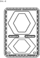
- FIG. 1 is a front view of a battery pack cover according to an embodiment of the present invention
- FIG. 2 is an enlarged view of part A of FIG. 1
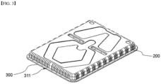
- FIG. 3 is a perspective view of a battery pack cover according to an embodiment of the present invention.
- the battery pack cover has a shape of a rectangular tray whose bottom direction is open to cover the top of the battery pack, and the battery pack cover has a structure that covers the battery pack tray in which the battery modules are accommodated.
- the battery pack cover may include a upper surface portion 100 that is plate-shaped and has bead-shaped recessed irregularities on one surface thereof; and a side portion 200 that is bent and extended from the upper surface portion 100, forms a plane perpendicular to the upper surface portion 100, and covers the upper side surface of the battery pack.
- the battery pack cover further includes a wing portion 300 that is bent and extended from the side portion 200 and forms a plane perpendicular to the side portion 200.
- the irregularities formed on the upper surface portion 100 include a first shape 110 having a closed figure shape and a second shape 120 having an open figure shape based on a center line connecting the center in the width direction of the irregularities.
- the area in which the center line is a straight line means an area having a length in the width direction (D1 and D2) with respect to the center line extending in a straight line, and the irregularities are in a form where the center line is recessed as much as a straight area.
- the first shape 110 forms a hexagonal structure having six sides when center lines connecting the centers in the width direction of the irregularities are connected.
- the first shape 110 further includes an irregularity that is perpendicular to the lower side of the hexagon.
- the second shape 120 forms a polygonal structure in which one side is open when center lines connecting the centers in the width direction of the irregularities are connected.
- the second shape 120 can be U-shaped with two sides that are at an angle to one another and a middle section extending between the two sides.
- the straight line areas forming the first shape 110 and the second shape 120 do not face corners of the upper surface portion 100 (corresponding to the condition 1), and adjacently connected center lines of the irregularities in the width direction having a shape, in which two or more straight line areas are connected, face one or more different sides among four sides of the upper surface portion (corresponding to the condition 2). Therefore, the two centerlines, which form a V-shape, have an angle between them that is large enough that the centerlines point to opposite sides of the upper surface portion. For example, extensions of the centerlines of the two irregularities forming the left side of the first shape 110 intersect the upper edge and lower edge of the upper surface portion.
- At least one of the straight line areas has a shape in which both ends thereof face two adjacent sides among four sides each having the same upper surface portion 100 (corresponding to the condition 3).
- the centerline of the irregularity is at an angle so that extensions of the centerline intersect adjacent sides of the upper surface portion which meet at a corner.
- each of the centerlines of the irregularities forming the sides of the first shape 110 and second shape 120 face two adjacent sides of the upper surface portion.
- the two adjacent sides refer to sides that are adjacent to each other that share one vertex in the upper surface portion of a quadrangular shape.
- a bead-shaped recessed portion in the form of a horizontal bar is formed in a central area of the upper surface portion 100 of the battery pack cover.
- the horizontal bar-shaped bead-shaped recessed portion is a central fastening portion 140 for fastening with a battery module mounted on the lower portion of the battery pack cover.
- the central fastening portion 140 has a bar shape crossing the upper surface portion 100 of the battery pack cover in the width direction, and the two central fastening portions 140 are formed to be spaced apart.
- a through hole 141 for fastening bolts is formed in the central fastening portion 140.
- the shape of the irregularities formed on the upper surface portion 100 of the battery pack further includes one or more bead-shaped recessed portions 130 formed independently of the first shape 110 and the second shape 120.
- the bead-shaped recessed portions 130 are formed on both sides of the lower edge of the upper surface portion 100 of the battery pack.
- the side portion 200 of the battery pack cover includes a corrugated structure oriented in a direction perpendicular to the upper surface portion 100.
- the corrugated structure of the side portion 200 includes irregularities that repeat protrusion and depression, and is arranged in a direction perpendicular to the upper surface portion 100.
- the wing portion 300 has a structure in which a plurality of perforations 311 for fastening with a battery pack tray are formed.
- FIG. 4 is a front view of a battery pack cover outside the scope of the present invention.
- irregularities having a shape of a closed figure are formed on the top and bottom, respectively.
- the remaining components except for the shape of the irregularities formed on the front portion are the same as the battery pack cover illustrated in FIG. 1 . Detailed description of the remaining components will be omitted.
- FIG. 5 is a schematic diagram showing a result of evaluating vibration performance for the battery pack cover shown in FIG. 1 through a simulation. Referring to FIG. 5 , it can be seen that stress is distributed along the shape of the protrusion formed on the upper surface portion of the battery pack cover. Among the protrusions formed on the upper surface portion of the battery pack cover, it was confirmed that the stress was evenly distributed along the first shape and the second shape.
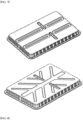
- FIGS. 6 to 8 show a battery pack cover according to a comparative example, respectively.
- FIG. 6 shows a structure in which a bead-shaped recessed portion in a quadrangle shape with rounded corners is formed on the front portion of the battery pack cover.
- FIG. 7 shows a structure in which a bar-shaped main recessed portion crosses the center of the front portion of the battery pack cover in the longitudinal direction, and a sub recessed portion radiating from the recessed portion toward an edge is formed.
- FIG. 8 a plurality of recessed portions crossing the center of the battery pack cover in the longitudinal direction are formed, and each recessed portion has a rectangle extending in the longitudinal direction.
- Battery pack covers of the shapes shown in FIGS. 1 and 4 were manufactured, respectively.
- Each of the battery pack covers of the shapes shown in FIGS. 6 to 8 was manufactured.
- Vibration performance evaluation was performed on the battery pack covers of Example 1 and Comparative Examples 1 to 3. In the evaluation, vibrations of various wavelengths were applied to each sample, and a range in which cracks occurred was calculated. The evaluation results are shown in Table 1 below. [Table 1] Example No. Evaluation result (Hz) Example 1 39.4 Comparative Example 1 18.6 Comparative Example 2 32.9 Comparative Example 3 35.1
- the battery pack cover according to Example 1 exhibits a result of vibration performance improved by two or more times compared to Comparative Example 1.
- Comparative Examples 2 and 3 it can be seen that the battery pack cover of Example 1 has remarkably excellent vibration performance.
Landscapes
- Chemical & Material Sciences (AREA)
- Chemical Kinetics & Catalysis (AREA)
- Electrochemistry (AREA)
- General Chemical & Material Sciences (AREA)
- Engineering & Computer Science (AREA)
- Aviation & Aerospace Engineering (AREA)
- Battery Mounting, Suspending (AREA)
- Sealing Battery Cases Or Jackets (AREA)
Claims (9)
- Batteriepackabdeckung in einer Form einer viereckigen Ablage, um einen oberen Abschnitt eines Batteriepacks abzudecken, wobei die Batteriepackabdeckung umfasst:einen plattenförmigen oberen Flächenabschnitt (100), welcher Unregelmäßigkeiten aufweist, wobei die Unregelmäßigkeiten entweder Vertiefungen oder Vorsprünge an einer oder beiden Seiten des oberen Flächenabschnitts (100) sind; undeinen Seitenabschnitt (200), welcher gebogen ist und sich von dem oberen Flächenabschnitt (100) erstreckt, welcher eine Ebene bildet, welche senkrecht zu dem oberen Flächenabschnitt (100) ist, und welcher eine obere Seitenfläche des Batteriepacks abdeckt,wobei die Unregelmäßigkeiten, welche an dem oberen Flächenabschnitt (100) gebildet sind, einen Bereich umfassen, in welchem eine Mittellinie eine gerade Linie ist, welche nachfolgende Bedingungen 1 bis 3 erfüllt:[Bedingung 1]
in einem Bereich, in welchem die Mittellinie eine gerade Linie ist, ist ein Ende der Mittellinie einer von vier Seiten des oberen Flächenabschnitts (100) zugewandt und ein entgegengesetztes Ende der Mittellinie ist einer anderen Seite zugewandt, sodass eine Erweiterung der Mittellinie eine Ecke des oberen Flächenabschnitts (100) nicht kreuzt;[Bedingung 2]
die Mittellinie jeder von zwei Unregelmäßigkeiten ist eine gerade Linie und sie sind verbunden, und die verbundenen Mittellinien sind zwei entgegengesetzten Seiten des oberen Flächenabschnitts (100) zugewandt; und[Bedingung 3]Enden einer Mittellinie einer Unregelmäßigkeit sind zwei benachbarten Seiten aus vier Seiten des oberen Flächenabschnitts (100) zugewandt,wobei jede der Unregelmäßigkeiten, welche an dem oberen Flächenabschnitt (100) gebildet ist, eine wulstförmige vertiefte Form aufweist, undwobei die Unregelmäßigkeiten an einer oberen Fläche des plattenförmigen oberen Flächenabschnitts (100) gebildet sind,wobei die an dem oberen Flächenabschnitt (100) gebildeten Unregelmäßigkeiten umfassen:eine erste Form (110), welche eine Form einer geschlossenen Figur aufweist, wobei die erste Form (110) eine polygonale Struktur mit vier oder mehr Seiten bildet, wenn die Mittellinien der Unregelmäßigkeiten verbunden werden; undeine zweite Form (120) mit einer Form einer offenen Figur, wobei die zweite Form (120) eine polygonale Struktur mit einer offenen Seite bildet. - Batteriepackabdeckung nach Anspruch 1, wobei die Unregelmäßigkeiten, welche an dem oberen Flächenabschnitt (100) gebildet sind, vier Seiten des oberen Flächenabschnitts (100) nicht kontaktieren.
- Batteriepackabdeckung nach Anspruch 1, wobei eine Breite der Unregelmäßigkeiten in einem Bereich von 5 bis 35 % einer Länge in einer kurzen Achsenrichtung des oberen Flächenabschnitts (100) liegt.
- Batteriepackabdeckung nach Anspruch 1, wobei ein Bereich, welcher darauf gebildete Unregelmäßigkeiten aufweist, in einem Bereich von 30 bis 65 % eines Gesamtbereichs des oberen Flächenabschnitts (100) liegt.
- Batteriepackabdeckung nach Anspruch 1, wobei ein Verhältnis aus einem Bereich der ersten Form (110) und einem Bereich der zweiten Form (120) in einem Bereich von 3 : 1 bis 1,2 : 1 liegt.
- Batteriepackabdeckung nach Anspruch 1, ferner umfassend einen oder mehrere wulstförmige vertiefte Abschnitte (130), welche unabhängig von den Unregelmäßigkeiten gebildet sind, welche an dem oberen Flächenabschnitt (100) gebildet sind.
- Batteriepackabdeckung nach Anspruch 1, wobei der Seitenabschnitt (200) Vorsprünge und Absenkungen umfasst, und
wobei ein Tal, welches durch die Vorsprünge und Absenkungen gebildet ist, senkrecht zu dem oberen Flächenabschnitt (100) ist. - Batteriepackabdeckung nach Anspruch 1, ferner umfassend einen Flügelabschnitt (300), welcher sich von dem Seitenabschnitt (200) erstreckt und eine Ebene bildet, welche senkrecht zu dem Seitenabschnitt (200) ist,
wobei eine Perforation zum Befestigen mit dem Batteriepack oder eine Batteriepackablage in dem Flügelabschnitt (300) gebildet ist. - Batteriepack, umfassend:eine Batteriepackablage, welche eine offene Fläche aufweist;ein Batteriemodul, welches in der Batteriepackablage aufgenommen ist; unddie Batteriepackabdeckung nach Anspruch 1, welche eine Struktur aufweist, welche die offene Fläche der Batteriepackablage abdeckt.
Applications Claiming Priority (2)
| Application Number | Priority Date | Filing Date | Title |
|---|---|---|---|
| KR1020190095996A KR102772385B1 (ko) | 2019-08-07 | 2019-08-07 | 표면 요철 구조를 갖는 전지팩 커버 및 이를 포함하는 전지팩 |
| PCT/KR2020/010475 WO2021025520A1 (ko) | 2019-08-07 | 2020-08-07 | 표면 요철 구조를 갖는 전지팩 커버 및 이를 포함하는 전지팩 |
Publications (3)
| Publication Number | Publication Date |
|---|---|
| EP3876339A1 EP3876339A1 (de) | 2021-09-08 |
| EP3876339A4 EP3876339A4 (de) | 2022-04-06 |
| EP3876339B1 true EP3876339B1 (de) | 2024-06-26 |
Family
ID=74502800
Family Applications (1)
| Application Number | Title | Priority Date | Filing Date |
|---|---|---|---|
| EP20850033.0A Active EP3876339B1 (de) | 2019-08-07 | 2020-08-07 | Abdeckung für akkupack mit unebener oberflächenstruktur und akkupack damit |
Country Status (9)
| Country | Link |
|---|---|
| US (1) | US12027720B2 (de) |
| EP (1) | EP3876339B1 (de) |
| JP (1) | JP7195438B2 (de) |
| KR (1) | KR102772385B1 (de) |
| CN (1) | CN113646959B (de) |
| ES (1) | ES2983862T3 (de) |
| HU (1) | HUE067523T2 (de) |
| PL (1) | PL3876339T3 (de) |
| WO (1) | WO2021025520A1 (de) |
Families Citing this family (1)
| Publication number | Priority date | Publication date | Assignee | Title |
|---|---|---|---|---|
| FR3148170B1 (fr) * | 2023-04-26 | 2025-03-14 | Psa Automobiles Sa | Caisson plat de batterie de traction de vehicule equipe d’un couvercle avec nervures de renfort inclinees |
Family Cites Families (40)
| Publication number | Priority date | Publication date | Assignee | Title |
|---|---|---|---|---|
| JP3350189B2 (ja) | 1993-04-30 | 2002-11-25 | 本田技研工業株式会社 | 電気自動車用バッテリボックス装置 |
| JP2006264717A (ja) | 2005-03-23 | 2006-10-05 | Bridgestone Corp | プラスチック容器 |
| CN200969361Y (zh) * | 2006-09-26 | 2007-10-31 | 比亚迪股份有限公司 | 一种锂离子电池壳体及包括该壳体的锂离子电池 |
| KR20090000397A (ko) | 2007-06-28 | 2009-01-07 | 에스케이 텔레콤주식회사 | 전자책 화면이동 방법 및 이에 적용되는 장치 |
| JP5340659B2 (ja) | 2008-07-07 | 2013-11-13 | 三洋電機株式会社 | 車両用の組電池 |
| JP2010284984A (ja) * | 2009-06-09 | 2010-12-24 | Fuji Heavy Ind Ltd | 車両用バッテリ搭載構造 |
| WO2012140727A1 (ja) | 2011-04-12 | 2012-10-18 | 日立ビークルエナジー株式会社 | 二次電池モジュール |
| KR101338290B1 (ko) | 2011-04-15 | 2013-12-09 | 주식회사 엘지화학 | 팩 커버와 엔드 플레이트의 결합 구조 및 이를 포함하는 전지팩 |
| KR101307369B1 (ko) * | 2011-05-23 | 2013-09-11 | 주식회사 엘지화학 | 안전성이 향상된 전지팩 |
| KR101345638B1 (ko) | 2012-03-06 | 2013-12-27 | 한화엘앤씨 주식회사 | 전기자동차용 하이브리드 배터리 모듈 커버 |
| KR101315741B1 (ko) | 2012-03-23 | 2013-10-10 | 현대자동차주식회사 | 치수안정성이 우수한 전기자동차용 배터리 팩 케이스 어셈블리와 그 제조 방법 |
| KR101478701B1 (ko) | 2012-03-26 | 2015-01-02 | 주식회사 엘지화학 | 용접 결합부 및 체결 만입부를 포함하는 결속 부재 및 이를 포함하는 전지모듈 어셈블리 |
| KR101478707B1 (ko) * | 2012-03-29 | 2015-01-02 | 주식회사 엘지화학 | 신규한 구조의 전지모듈 어셈블리용 베이스 플레이트 |
| JP5037740B1 (ja) | 2012-05-29 | 2012-10-03 | 日立マクセルエナジー株式会社 | 電池ケース及びそれを備えた電池パック |
| US20140014418A1 (en) * | 2012-07-16 | 2014-01-16 | Tsuyoshi Komaki | Power supply device, power-supply-device separator, and power-supply-device-equipped vehicle |
| FR2996094B1 (fr) | 2012-09-27 | 2014-10-17 | Sonic Emotion Labs | Procede et systeme de restitution d'un signal audio |
| JP6120996B2 (ja) * | 2013-05-15 | 2017-04-26 | エルジー・ケム・リミテッド | 新規な構造の電池モジュールアセンブリー用ベースプレート |
| WO2014185567A1 (ko) | 2013-05-15 | 2014-11-20 | 주식회사 엘지화학 | 신규한 구조의 전지모듈 어셈블리 |
| JP6098381B2 (ja) * | 2013-06-07 | 2017-03-22 | 日産自動車株式会社 | 車両用バッテリケース |
| KR101675972B1 (ko) | 2013-07-31 | 2016-11-29 | 주식회사 엘지화학 | 외부 장착 구조를 포함하는 전지팩 |
| KR101729553B1 (ko) | 2013-08-23 | 2017-04-24 | 주식회사 엘지화학 | 전력 저장 장치용 전지팩 |
| KR101807113B1 (ko) | 2013-11-29 | 2017-12-08 | 주식회사 엘지화학 | 배터리 팩 |
| JP6303729B2 (ja) * | 2014-03-31 | 2018-04-04 | 日本電気株式会社 | 電池パックおよび電池パックの製造方法 |
| WO2015186849A1 (ko) * | 2014-06-03 | 2015-12-10 | 삼성에스디아이 주식회사 | 전지 트레이 |
| JP6065294B2 (ja) * | 2014-09-30 | 2017-01-25 | パナソニックIpマネジメント株式会社 | パウチ型電池 |
| KR101733269B1 (ko) | 2014-12-12 | 2017-05-08 | 주식회사 엘지화학 | 전지모듈 |
| JP2017010777A (ja) | 2015-06-22 | 2017-01-12 | カルソニックカンセイ株式会社 | 組電池及び電源装置 |
| KR102065096B1 (ko) * | 2016-02-12 | 2020-01-10 | 주식회사 엘지화학 | 배터리 팩 |
| KR102562681B1 (ko) * | 2016-03-15 | 2023-08-03 | 삼성에스디아이 주식회사 | 이차전지 |
| CN206076324U (zh) * | 2016-09-22 | 2017-04-05 | 广州汽车集团股份有限公司 | 车用电池包下壳体结构、电池包壳体及电池包 |
| KR20180059146A (ko) | 2016-11-25 | 2018-06-04 | (주)오라컴디스플레이 | 방수 기능을 갖는 배터리 장치 |
| JP2019050150A (ja) * | 2017-09-11 | 2019-03-28 | 三菱自動車工業株式会社 | 蓋体の取付構造 |
| KR102159347B1 (ko) | 2017-11-14 | 2020-09-23 | 주식회사 엘지화학 | 배터리 셀 가압형 엔드 플레이트와 확장형 센싱 하우징 구조가 적용된 배터리 모듈 |
| CN109994669B (zh) * | 2017-12-29 | 2021-11-26 | 上海电巴新能源科技有限公司 | 电池包总成及含其的电动车 |
| KR102140437B1 (ko) | 2018-02-08 | 2020-08-03 | 주식회사 셀바스에이아이 | 암 의심 영역의 예측 방법 및 이를 이용한 암 의심 영역의 예측 디바이스 |
| CN208014769U (zh) * | 2018-03-15 | 2018-10-26 | 合肥国轩高科动力能源有限公司 | 一种动力汽车的电池箱体 |
| FR3062521B1 (fr) | 2018-04-10 | 2023-09-08 | Sogefi Air & Cooling | Unite de batterie avec des moyens de regulation de la temperature integres au boitier |
| CN208240756U (zh) * | 2018-04-27 | 2018-12-14 | 苏州宇量电池有限公司 | 一种锂离子电池包箱体结构 |
| JP3217964U (ja) * | 2018-07-02 | 2018-09-13 | 株式会社Sumco | 半導体ウェーハ収納容器の梱包用緩衝体 |
| CN109149004A (zh) | 2018-07-19 | 2019-01-04 | 柯班 | 一种新能源汽车用动力电池箱装置 |
-
2019
- 2019-08-07 KR KR1020190095996A patent/KR102772385B1/ko active Active
-
2020
- 2020-08-07 EP EP20850033.0A patent/EP3876339B1/de active Active
- 2020-08-07 WO PCT/KR2020/010475 patent/WO2021025520A1/ko not_active Ceased
- 2020-08-07 US US17/311,839 patent/US12027720B2/en active Active
- 2020-08-07 JP JP2021532092A patent/JP7195438B2/ja active Active
- 2020-08-07 ES ES20850033T patent/ES2983862T3/es active Active
- 2020-08-07 PL PL20850033.0T patent/PL3876339T3/pl unknown
- 2020-08-07 HU HUE20850033A patent/HUE067523T2/hu unknown
- 2020-08-07 CN CN202080025341.8A patent/CN113646959B/zh active Active
Also Published As
| Publication number | Publication date |
|---|---|
| PL3876339T3 (pl) | 2024-08-26 |
| EP3876339A4 (de) | 2022-04-06 |
| JP7195438B2 (ja) | 2022-12-23 |
| JP2022511857A (ja) | 2022-02-01 |
| HUE067523T2 (hu) | 2024-10-28 |
| KR20210017169A (ko) | 2021-02-17 |
| KR102772385B1 (ko) | 2025-02-25 |
| WO2021025520A1 (ko) | 2021-02-11 |
| EP3876339A1 (de) | 2021-09-08 |
| US20220021066A1 (en) | 2022-01-20 |
| ES2983862T3 (es) | 2024-10-25 |
| CN113646959B (zh) | 2023-10-13 |
| CN113646959A (zh) | 2021-11-12 |
| US12027720B2 (en) | 2024-07-02 |
Similar Documents
| Publication | Publication Date | Title |
|---|---|---|
| EP3401976B1 (de) | Batteriepack | |
| EP2490276B1 (de) | Batteriemodul mit hervorragender struktureller stabilität | |
| KR101223567B1 (ko) | 전지 모듈 | |
| US10622599B2 (en) | Battery module of excellent structural stability | |
| CN103155210B (zh) | 具有改进耐久性的电池组 | |
| KR102532699B1 (ko) | 전지 모듈 및 이를 포함하는 전지팩 | |
| JP2007048750A (ja) | 電池モジュール | |
| KR101883386B1 (ko) | 전지 압축 저지체와 이를 포함하는 전지 모듈 | |
| CN107112462A (zh) | 夹持装置和包括该夹持装置的电池模块 | |
| EP3876339B1 (de) | Abdeckung für akkupack mit unebener oberflächenstruktur und akkupack damit | |
| US20250286201A1 (en) | Electricity storage device | |
| CN114843687A (zh) | 保护组件以及包括该保护组件的电池壳体 | |
| KR101797690B1 (ko) | 절연 돌출부가 형성되어 있는 버스 바 어셈블리를 포함하는 전지팩 | |
| KR102861319B1 (ko) | 전지 모듈 | |
| US20140255760A1 (en) | Battery pack and battery module including the same | |
| KR102916361B1 (ko) | 전지 모듈 | |
| KR102900632B1 (ko) | 플랜지 형태의 홀딩 구조를 포함하는 전지 팩 케이스 및 이를 포함하는 전지 팩 | |
| KR102958979B1 (ko) | 전지 모듈 및 이를 포함하는 전지팩 | |
| US20250300313A1 (en) | Electric storage device | |
| EP4270604A1 (de) | Batteriepack mit verbesserter kühlleistung und fahrzeug damit | |
| KR20240117359A (ko) | 배터리팩 및 배터리팩 프레임 | |
| CN121548902A (zh) | 电池组和包括该电池组的车辆 | |
| KR20240055659A (ko) | 전지 모듈 | |
| TW202527361A (zh) | 電池組 | |
| KR20240055660A (ko) | 전지 모듈 및 그 제조 방법 |
Legal Events
| Date | Code | Title | Description |
|---|---|---|---|
| STAA | Information on the status of an ep patent application or granted ep patent |
Free format text: STATUS: THE INTERNATIONAL PUBLICATION HAS BEEN MADE |
|
| PUAI | Public reference made under article 153(3) epc to a published international application that has entered the european phase |
Free format text: ORIGINAL CODE: 0009012 |
|
| STAA | Information on the status of an ep patent application or granted ep patent |
Free format text: STATUS: REQUEST FOR EXAMINATION WAS MADE |
|
| 17P | Request for examination filed |
Effective date: 20210603 |
|
| AK | Designated contracting states |
Kind code of ref document: A1 Designated state(s): AL AT BE BG CH CY CZ DE DK EE ES FI FR GB GR HR HU IE IS IT LI LT LU LV MC MK MT NL NO PL PT RO RS SE SI SK SM TR |
|
| REG | Reference to a national code |
Ref country code: DE Ref legal event code: R079 Free format text: PREVIOUS MAIN CLASS: H01M0050200000 Ipc: H01M0050207000 Ref country code: DE Ref legal event code: R079 Ref document number: 602020033117 Country of ref document: DE Free format text: PREVIOUS MAIN CLASS: H01M0050200000 Ipc: H01M0050207000 |
|
| RAP3 | Party data changed (applicant data changed or rights of an application transferred) |
Owner name: LG ENERGY SOLUTION, LTD. |
|
| A4 | Supplementary search report drawn up and despatched |
Effective date: 20220309 |
|
| RIC1 | Information provided on ipc code assigned before grant |
Ipc: H01M 50/242 20210101ALI20220302BHEP Ipc: H01M 50/207 20210101AFI20220302BHEP |
|
| DAV | Request for validation of the european patent (deleted) | ||
| DAX | Request for extension of the european patent (deleted) | ||
| GRAP | Despatch of communication of intention to grant a patent |
Free format text: ORIGINAL CODE: EPIDOSNIGR1 |
|
| STAA | Information on the status of an ep patent application or granted ep patent |
Free format text: STATUS: GRANT OF PATENT IS INTENDED |
|
| INTG | Intention to grant announced |
Effective date: 20240229 |
|
| P01 | Opt-out of the competence of the unified patent court (upc) registered |
Effective date: 20240301 |
|
| GRAS | Grant fee paid |
Free format text: ORIGINAL CODE: EPIDOSNIGR3 |
|
| GRAA | (expected) grant |
Free format text: ORIGINAL CODE: 0009210 |
|
| STAA | Information on the status of an ep patent application or granted ep patent |
Free format text: STATUS: THE PATENT HAS BEEN GRANTED |
|
| AK | Designated contracting states |
Kind code of ref document: B1 Designated state(s): AL AT BE BG CH CY CZ DE DK EE ES FI FR GB GR HR HU IE IS IT LI LT LU LV MC MK MT NL NO PL PT RO RS SE SI SK SM TR |
|
| REG | Reference to a national code |
Ref country code: GB Ref legal event code: FG4D |
|
| REG | Reference to a national code |
Ref country code: CH Ref legal event code: EP |
|
| REG | Reference to a national code |
Ref country code: DE Ref legal event code: R096 Ref document number: 602020033117 Country of ref document: DE |
|
| REG | Reference to a national code |
Ref country code: SE Ref legal event code: TRGR |
|
| PG25 | Lapsed in a contracting state [announced via postgrant information from national office to epo] |
Ref country code: BG Free format text: LAPSE BECAUSE OF FAILURE TO SUBMIT A TRANSLATION OF THE DESCRIPTION OR TO PAY THE FEE WITHIN THE PRESCRIBED TIME-LIMIT Effective date: 20240626 |
|
| PG25 | Lapsed in a contracting state [announced via postgrant information from national office to epo] |
Ref country code: HR Free format text: LAPSE BECAUSE OF FAILURE TO SUBMIT A TRANSLATION OF THE DESCRIPTION OR TO PAY THE FEE WITHIN THE PRESCRIBED TIME-LIMIT Effective date: 20240626 Ref country code: FI Free format text: LAPSE BECAUSE OF FAILURE TO SUBMIT A TRANSLATION OF THE DESCRIPTION OR TO PAY THE FEE WITHIN THE PRESCRIBED TIME-LIMIT Effective date: 20240626 |
|
| REG | Reference to a national code |
Ref country code: LT Ref legal event code: MG9D |
|
| PG25 | Lapsed in a contracting state [announced via postgrant information from national office to epo] |
Ref country code: GR Free format text: LAPSE BECAUSE OF FAILURE TO SUBMIT A TRANSLATION OF THE DESCRIPTION OR TO PAY THE FEE WITHIN THE PRESCRIBED TIME-LIMIT Effective date: 20240927 |
|
| REG | Reference to a national code |
Ref country code: ES Ref legal event code: FG2A Ref document number: 2983862 Country of ref document: ES Kind code of ref document: T3 Effective date: 20241025 |
|
| REG | Reference to a national code |
Ref country code: HU Ref legal event code: AG4A Ref document number: E067523 Country of ref document: HU |
|
| PG25 | Lapsed in a contracting state [announced via postgrant information from national office to epo] |
Ref country code: LV Free format text: LAPSE BECAUSE OF FAILURE TO SUBMIT A TRANSLATION OF THE DESCRIPTION OR TO PAY THE FEE WITHIN THE PRESCRIBED TIME-LIMIT Effective date: 20240626 |
|
| REG | Reference to a national code |
Ref country code: NL Ref legal event code: MP Effective date: 20240626 |
|
| PG25 | Lapsed in a contracting state [announced via postgrant information from national office to epo] |
Ref country code: NO Free format text: LAPSE BECAUSE OF FAILURE TO SUBMIT A TRANSLATION OF THE DESCRIPTION OR TO PAY THE FEE WITHIN THE PRESCRIBED TIME-LIMIT Effective date: 20240926 Ref country code: LV Free format text: LAPSE BECAUSE OF FAILURE TO SUBMIT A TRANSLATION OF THE DESCRIPTION OR TO PAY THE FEE WITHIN THE PRESCRIBED TIME-LIMIT Effective date: 20240626 Ref country code: HR Free format text: LAPSE BECAUSE OF FAILURE TO SUBMIT A TRANSLATION OF THE DESCRIPTION OR TO PAY THE FEE WITHIN THE PRESCRIBED TIME-LIMIT Effective date: 20240626 Ref country code: GR Free format text: LAPSE BECAUSE OF FAILURE TO SUBMIT A TRANSLATION OF THE DESCRIPTION OR TO PAY THE FEE WITHIN THE PRESCRIBED TIME-LIMIT Effective date: 20240927 Ref country code: FI Free format text: LAPSE BECAUSE OF FAILURE TO SUBMIT A TRANSLATION OF THE DESCRIPTION OR TO PAY THE FEE WITHIN THE PRESCRIBED TIME-LIMIT Effective date: 20240626 Ref country code: BG Free format text: LAPSE BECAUSE OF FAILURE TO SUBMIT A TRANSLATION OF THE DESCRIPTION OR TO PAY THE FEE WITHIN THE PRESCRIBED TIME-LIMIT Effective date: 20240626 Ref country code: RS Free format text: LAPSE BECAUSE OF FAILURE TO SUBMIT A TRANSLATION OF THE DESCRIPTION OR TO PAY THE FEE WITHIN THE PRESCRIBED TIME-LIMIT Effective date: 20240926 |
|
| PG25 | Lapsed in a contracting state [announced via postgrant information from national office to epo] |
Ref country code: NL Free format text: LAPSE BECAUSE OF FAILURE TO SUBMIT A TRANSLATION OF THE DESCRIPTION OR TO PAY THE FEE WITHIN THE PRESCRIBED TIME-LIMIT Effective date: 20240626 |
|
| REG | Reference to a national code |
Ref country code: AT Ref legal event code: MK05 Ref document number: 1698480 Country of ref document: AT Kind code of ref document: T Effective date: 20240626 |
|
| PG25 | Lapsed in a contracting state [announced via postgrant information from national office to epo] |
Ref country code: NL Free format text: LAPSE BECAUSE OF FAILURE TO SUBMIT A TRANSLATION OF THE DESCRIPTION OR TO PAY THE FEE WITHIN THE PRESCRIBED TIME-LIMIT Effective date: 20240626 |
|
| PG25 | Lapsed in a contracting state [announced via postgrant information from national office to epo] |
Ref country code: PT Free format text: LAPSE BECAUSE OF FAILURE TO SUBMIT A TRANSLATION OF THE DESCRIPTION OR TO PAY THE FEE WITHIN THE PRESCRIBED TIME-LIMIT Effective date: 20241028 |
|
| PG25 | Lapsed in a contracting state [announced via postgrant information from national office to epo] |
Ref country code: PT Free format text: LAPSE BECAUSE OF FAILURE TO SUBMIT A TRANSLATION OF THE DESCRIPTION OR TO PAY THE FEE WITHIN THE PRESCRIBED TIME-LIMIT Effective date: 20241028 |
|
| PG25 | Lapsed in a contracting state [announced via postgrant information from national office to epo] |
Ref country code: EE Free format text: LAPSE BECAUSE OF FAILURE TO SUBMIT A TRANSLATION OF THE DESCRIPTION OR TO PAY THE FEE WITHIN THE PRESCRIBED TIME-LIMIT Effective date: 20240626 |
|
| PG25 | Lapsed in a contracting state [announced via postgrant information from national office to epo] |
Ref country code: AT Free format text: LAPSE BECAUSE OF FAILURE TO SUBMIT A TRANSLATION OF THE DESCRIPTION OR TO PAY THE FEE WITHIN THE PRESCRIBED TIME-LIMIT Effective date: 20240626 Ref country code: IS Free format text: LAPSE BECAUSE OF FAILURE TO SUBMIT A TRANSLATION OF THE DESCRIPTION OR TO PAY THE FEE WITHIN THE PRESCRIBED TIME-LIMIT Effective date: 20241026 |
|
| PG25 | Lapsed in a contracting state [announced via postgrant information from national office to epo] |
Ref country code: CZ Free format text: LAPSE BECAUSE OF FAILURE TO SUBMIT A TRANSLATION OF THE DESCRIPTION OR TO PAY THE FEE WITHIN THE PRESCRIBED TIME-LIMIT Effective date: 20240626 |
|
| PG25 | Lapsed in a contracting state [announced via postgrant information from national office to epo] |
Ref country code: RO Free format text: LAPSE BECAUSE OF FAILURE TO SUBMIT A TRANSLATION OF THE DESCRIPTION OR TO PAY THE FEE WITHIN THE PRESCRIBED TIME-LIMIT Effective date: 20240626 Ref country code: SK Free format text: LAPSE BECAUSE OF FAILURE TO SUBMIT A TRANSLATION OF THE DESCRIPTION OR TO PAY THE FEE WITHIN THE PRESCRIBED TIME-LIMIT Effective date: 20240626 |
|
| PG25 | Lapsed in a contracting state [announced via postgrant information from national office to epo] |
Ref country code: SM Free format text: LAPSE BECAUSE OF FAILURE TO SUBMIT A TRANSLATION OF THE DESCRIPTION OR TO PAY THE FEE WITHIN THE PRESCRIBED TIME-LIMIT Effective date: 20240626 |
|
| PG25 | Lapsed in a contracting state [announced via postgrant information from national office to epo] |
Ref country code: SM Free format text: LAPSE BECAUSE OF FAILURE TO SUBMIT A TRANSLATION OF THE DESCRIPTION OR TO PAY THE FEE WITHIN THE PRESCRIBED TIME-LIMIT Effective date: 20240626 Ref country code: SK Free format text: LAPSE BECAUSE OF FAILURE TO SUBMIT A TRANSLATION OF THE DESCRIPTION OR TO PAY THE FEE WITHIN THE PRESCRIBED TIME-LIMIT Effective date: 20240626 Ref country code: RO Free format text: LAPSE BECAUSE OF FAILURE TO SUBMIT A TRANSLATION OF THE DESCRIPTION OR TO PAY THE FEE WITHIN THE PRESCRIBED TIME-LIMIT Effective date: 20240626 Ref country code: IS Free format text: LAPSE BECAUSE OF FAILURE TO SUBMIT A TRANSLATION OF THE DESCRIPTION OR TO PAY THE FEE WITHIN THE PRESCRIBED TIME-LIMIT Effective date: 20241026 Ref country code: EE Free format text: LAPSE BECAUSE OF FAILURE TO SUBMIT A TRANSLATION OF THE DESCRIPTION OR TO PAY THE FEE WITHIN THE PRESCRIBED TIME-LIMIT Effective date: 20240626 Ref country code: CZ Free format text: LAPSE BECAUSE OF FAILURE TO SUBMIT A TRANSLATION OF THE DESCRIPTION OR TO PAY THE FEE WITHIN THE PRESCRIBED TIME-LIMIT Effective date: 20240626 Ref country code: AT Free format text: LAPSE BECAUSE OF FAILURE TO SUBMIT A TRANSLATION OF THE DESCRIPTION OR TO PAY THE FEE WITHIN THE PRESCRIBED TIME-LIMIT Effective date: 20240626 |
|
| PG25 | Lapsed in a contracting state [announced via postgrant information from national office to epo] |
Ref country code: IT Free format text: LAPSE BECAUSE OF FAILURE TO SUBMIT A TRANSLATION OF THE DESCRIPTION OR TO PAY THE FEE WITHIN THE PRESCRIBED TIME-LIMIT Effective date: 20240626 |
|
| REG | Reference to a national code |
Ref country code: DE Ref legal event code: R097 Ref document number: 602020033117 Country of ref document: DE |
|
| REG | Reference to a national code |
Ref country code: CH Ref legal event code: PL |
|
| PG25 | Lapsed in a contracting state [announced via postgrant information from national office to epo] |
Ref country code: DK Free format text: LAPSE BECAUSE OF FAILURE TO SUBMIT A TRANSLATION OF THE DESCRIPTION OR TO PAY THE FEE WITHIN THE PRESCRIBED TIME-LIMIT Effective date: 20240626 |
|
| PG25 | Lapsed in a contracting state [announced via postgrant information from national office to epo] |
Ref country code: LU Free format text: LAPSE BECAUSE OF NON-PAYMENT OF DUE FEES Effective date: 20240807 |
|
| PG25 | Lapsed in a contracting state [announced via postgrant information from national office to epo] |
Ref country code: MC Free format text: LAPSE BECAUSE OF FAILURE TO SUBMIT A TRANSLATION OF THE DESCRIPTION OR TO PAY THE FEE WITHIN THE PRESCRIBED TIME-LIMIT Effective date: 20240626 Ref country code: CH Free format text: LAPSE BECAUSE OF NON-PAYMENT OF DUE FEES Effective date: 20240831 |
|
| PLBE | No opposition filed within time limit |
Free format text: ORIGINAL CODE: 0009261 |
|
| STAA | Information on the status of an ep patent application or granted ep patent |
Free format text: STATUS: NO OPPOSITION FILED WITHIN TIME LIMIT |
|
| 26N | No opposition filed |
Effective date: 20250327 |
|
| REG | Reference to a national code |
Ref country code: BE Ref legal event code: MM Effective date: 20240831 |
|
| PG25 | Lapsed in a contracting state [announced via postgrant information from national office to epo] |
Ref country code: BE Free format text: LAPSE BECAUSE OF NON-PAYMENT OF DUE FEES Effective date: 20240831 |
|
| PG25 | Lapsed in a contracting state [announced via postgrant information from national office to epo] |
Ref country code: IE Free format text: LAPSE BECAUSE OF NON-PAYMENT OF DUE FEES Effective date: 20240807 |
|
| PGFP | Annual fee paid to national office [announced via postgrant information from national office to epo] |
Ref country code: HU Payment date: 20250827 Year of fee payment: 6 |
|
| PGFP | Annual fee paid to national office [announced via postgrant information from national office to epo] |
Ref country code: ES Payment date: 20250911 Year of fee payment: 6 |
|
| PGFP | Annual fee paid to national office [announced via postgrant information from national office to epo] |
Ref country code: DE Payment date: 20250721 Year of fee payment: 6 |
|
| PGFP | Annual fee paid to national office [announced via postgrant information from national office to epo] |
Ref country code: PL Payment date: 20250723 Year of fee payment: 6 |
|
| PGFP | Annual fee paid to national office [announced via postgrant information from national office to epo] |
Ref country code: GB Payment date: 20250722 Year of fee payment: 6 |
|
| PGFP | Annual fee paid to national office [announced via postgrant information from national office to epo] |
Ref country code: FR Payment date: 20250725 Year of fee payment: 6 |
|
| PGFP | Annual fee paid to national office [announced via postgrant information from national office to epo] |
Ref country code: SE Payment date: 20250722 Year of fee payment: 6 |
|
| PG25 | Lapsed in a contracting state [announced via postgrant information from national office to epo] |
Ref country code: CY Free format text: LAPSE BECAUSE OF FAILURE TO SUBMIT A TRANSLATION OF THE DESCRIPTION OR TO PAY THE FEE WITHIN THE PRESCRIBED TIME-LIMIT; INVALID AB INITIO Effective date: 20200807 |