EP3875977A1 - Magnetic detection system - Google Patents
Magnetic detection system Download PDFInfo
- Publication number
- EP3875977A1 EP3875977A1 EP21158729.0A EP21158729A EP3875977A1 EP 3875977 A1 EP3875977 A1 EP 3875977A1 EP 21158729 A EP21158729 A EP 21158729A EP 3875977 A1 EP3875977 A1 EP 3875977A1
- Authority
- EP
- European Patent Office
- Prior art keywords
- magnetic
- determination result
- unit
- determination
- output
- Prior art date
- Legal status (The legal status is an assumption and is not a legal conclusion. Google has not performed a legal analysis and makes no representation as to the accuracy of the status listed.)
- Granted
Links
Images






Classifications
-
- G—PHYSICS
- G01—MEASURING; TESTING
- G01R—MEASURING ELECTRIC VARIABLES; MEASURING MAGNETIC VARIABLES
- G01R33/00—Arrangements or instruments for measuring magnetic variables
- G01R33/02—Measuring direction or magnitude of magnetic fields or magnetic flux
-
- G—PHYSICS
- G01—MEASURING; TESTING
- G01D—MEASURING NOT SPECIALLY ADAPTED FOR A SPECIFIC VARIABLE; ARRANGEMENTS FOR MEASURING TWO OR MORE VARIABLES NOT COVERED IN A SINGLE OTHER SUBCLASS; TARIFF METERING APPARATUS; MEASURING OR TESTING NOT OTHERWISE PROVIDED FOR
- G01D5/00—Mechanical means for transferring the output of a sensing member; Means for converting the output of a sensing member to another variable where the form or nature of the sensing member does not constrain the means for converting; Transducers not specially adapted for a specific variable
- G01D5/12—Mechanical means for transferring the output of a sensing member; Means for converting the output of a sensing member to another variable where the form or nature of the sensing member does not constrain the means for converting; Transducers not specially adapted for a specific variable using electric or magnetic means
- G01D5/14—Mechanical means for transferring the output of a sensing member; Means for converting the output of a sensing member to another variable where the form or nature of the sensing member does not constrain the means for converting; Transducers not specially adapted for a specific variable using electric or magnetic means influencing the magnitude of a current or voltage
-
- B—PERFORMING OPERATIONS; TRANSPORTING
- B63—SHIPS OR OTHER WATERBORNE VESSELS; RELATED EQUIPMENT
- B63C—LAUNCHING, HAULING-OUT, OR DRY-DOCKING OF VESSELS; LIFE-SAVING IN WATER; EQUIPMENT FOR DWELLING OR WORKING UNDER WATER; MEANS FOR SALVAGING OR SEARCHING FOR UNDERWATER OBJECTS
- B63C11/00—Equipment for dwelling or working underwater; Means for searching for underwater objects
- B63C11/48—Means for searching for underwater objects
-
- G—PHYSICS
- G01—MEASURING; TESTING
- G01R—MEASURING ELECTRIC VARIABLES; MEASURING MAGNETIC VARIABLES
- G01R33/00—Arrangements or instruments for measuring magnetic variables
- G01R33/0023—Electronic aspects, e.g. circuits for stimulation, evaluation, control; Treating the measured signals; calibration
-
- G—PHYSICS
- G01—MEASURING; TESTING
- G01V—GEOPHYSICS; GRAVITATIONAL MEASUREMENTS; DETECTING MASSES OR OBJECTS; TAGS
- G01V3/00—Electric or magnetic prospecting or detecting; Measuring magnetic field characteristics of the earth, e.g. declination, deviation
- G01V3/08—Electric or magnetic prospecting or detecting; Measuring magnetic field characteristics of the earth, e.g. declination, deviation operating with magnetic or electric fields produced or modified by objects or geological structures or by detecting devices
- G01V3/081—Electric or magnetic prospecting or detecting; Measuring magnetic field characteristics of the earth, e.g. declination, deviation operating with magnetic or electric fields produced or modified by objects or geological structures or by detecting devices the magnetic field is produced by the objects or geological structures
-
- G—PHYSICS
- G06—COMPUTING OR CALCULATING; COUNTING
- G06N—COMPUTING ARRANGEMENTS BASED ON SPECIFIC COMPUTATIONAL MODELS
- G06N20/00—Machine learning
-
- G—PHYSICS
- G06—COMPUTING OR CALCULATING; COUNTING
- G06N—COMPUTING ARRANGEMENTS BASED ON SPECIFIC COMPUTATIONAL MODELS
- G06N20/00—Machine learning
- G06N20/20—Ensemble learning
-
- B—PERFORMING OPERATIONS; TRANSPORTING
- B63—SHIPS OR OTHER WATERBORNE VESSELS; RELATED EQUIPMENT
- B63B—SHIPS OR OTHER WATERBORNE VESSELS; EQUIPMENT FOR SHIPPING
- B63B2231/00—Material used for some parts or elements, or for particular purposes
- B63B2231/30—Magnetic materials
-
- Y—GENERAL TAGGING OF NEW TECHNOLOGICAL DEVELOPMENTS; GENERAL TAGGING OF CROSS-SECTIONAL TECHNOLOGIES SPANNING OVER SEVERAL SECTIONS OF THE IPC; TECHNICAL SUBJECTS COVERED BY FORMER USPC CROSS-REFERENCE ART COLLECTIONS [XRACs] AND DIGESTS
- Y02—TECHNOLOGIES OR APPLICATIONS FOR MITIGATION OR ADAPTATION AGAINST CLIMATE CHANGE
- Y02A—TECHNOLOGIES FOR ADAPTATION TO CLIMATE CHANGE
- Y02A90/00—Technologies having an indirect contribution to adaptation to climate change
- Y02A90/30—Assessment of water resources
Definitions
- the present invention relates to a magnetic detection system, and more specifically to a magnetic body detection system equipped with a magnetic sensor for detecting a magnetic body.
- a magnetic detection system in which a magnetic sensor is equipped to detect a magnetic body.
- a magnetic detection system is disclosed, for example, in Japanese Unexamined Patent Application Publication No. 2013-156225 .
- Japanese Unexamined Patent Application Publication No. 2013-156225 discloses a magnetic detection system including a magnetic sensor, a calculation unit, and a determination unit.
- the magnetic detection system disclosed in Japanese Unexamined Patent Application Publication No. 2013-156225 is configured to detect a magnetic body (detection target) passing through the vicinity of the magnetic sensor.
- the magnetic sensor is installed underwater.
- the calculation unit is configured to perform an operation on the approximation degree of the magnetic waveform measured by the magnetic sensor and the predictable noise fluctuation. Further, the calculation unit is configured to perform an operation on the approximation degree of the magnetic waveform measured by the magnetic sensor and the theoretical standard waveform caused by the magnetic body.
- the determination unit is configured to perform a determination relating to the detection of the magnetic signal, based on the calculation result of the arithmetic unit.
- the magnetic detection system as disclosed in Japanese Unexamined Patent Application Publication No. 2013-156225 , it is generally used for detecting a magnetic body approaching a port or the like.
- the detection of the approach of the magnetic body requires both the determination accuracy and the immediacy from the security-related standpoint.
- To ensure the immediacy it is conceivable to determine using a part of the magnetic waveform caused by the magnetic body.
- the determination accuracy is lowered. Therefore, in order to compensate for the lowered determination accuracy, it is conceivable to determine by a monitoring person whether or not the magnetic waveform is caused by the magnetic body by directly confirming the magnetic waveform. In this case, the burden on the monitoring person increases. Under the circumstance, a magnetic detection system capable of reducing the burden on the monitoring person while ensuring the immediacy and the determination accuracy is desired.
- the present invention has been made to solve the above-described problems, and an object of the present invention is to provide a magnetic detection system capable of reducing a burden on a monitoring person while ensuring immediacy and determination accuracy.
- a magnetic detection system includes:
- the magnetic detection system by configuring as described above, the first determination result and the second determination result that differ from each other in the output timing and the determination accuracy are notified. Therefore, the monitoring person can determine whether or not a magnetic body has passed, based on the first determination result earlier in the output timing and the second determination result higher in the determination accuracy than the first determination result. Further, the first determination result and the second determination result, which indicate whether or not the magnetic body has passed, are outputted. Therefore, the burden on the monitoring person can be reduced, as compared with the configuration in which the monitoring person determines whether or not it is a magnetic signal caused by a magnetic body by directly confirming the magnetic signal. Consequently, it is possible to provide a magnetic detection system capable of reducing the burden on the monitoring person while ensuring immediacy and determination accuracy.
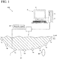
- FIG. 1 to FIG. 7 a configuration of a magnetic detection system 100 according to an embodiment will be described.
- the magnetic detection system 100 is provided with, as shown in FIG. 1 , a magnetic sensor 1, a receiving unit 2, and a computer 3.
- the magnetic detection system 100 of this embodiment detects whether or not the magnetic body 90 has passed by detecting a magnetic signal 10 emitted from the magnetic body 90. Based on the detection result output by the magnetic detection system 100, the monitoring person can recognize whether or not the magnetic body 90 has passed and can consider the countermeasures in accordance with whether or not the magnetic body 90 has passed.
- the magnetic sensor 1 is installed, for example, in ports and harbors.
- the magnetic body 90 sensed by the magnetic detection system 100 includes, for example, a vessel or the like.
- the magnetic sensor 1 is installed underwater.
- a plurality of the magnetic sensors 1 for detecting the passage of the magnetic body 90 is installed in the region 91.
- the magnetic sensor 1 includes, for example, a first magnetic sensor 1a, a second magnetic sensor 1b, a third magnetic sensor 1c, a fourth magnetic sensor 1d, a fifth magnetic sensor 1e, a sixth magnetic sensor 1f, a seventh magnetic sensor 1g, and an eighth magnetic sensor 1h.
- the plurality of magnetic sensors 1 is spaced apart from each other in the region 91.
- the magnetic sensors 1 are connected to the receiving unit 2 with a wire.
- the magnetic sensor 1 is configured to acquire a magnetic signal 10 caused by the passage of the magnetic body 90.
- Each magnetic sensor 1 is configured to output, for example, the acquired magnetic signal 10 to the receiving unit 2 installed on land as an optical signal.
- the magnetic sensor 1 includes, for example, a flux gate type sensor.
- the receiving unit 2 is wired to the magnetic sensor 1.
- the receiving unit 2 is wired to the computer 3.
- the receiving unit 2 is configured to output the magnetic signal 10 acquired by the magnetic sensor 1 to the computer 3.
- the receiving unit 2 includes, for example, a transducer that converts the magnetic signal 10 input as an optical signal into an electric signal.
- the computer 3 includes a control unit 4, a storage unit 5, and a display unit 6.
- the display unit 6 is an example of the "notification unit" recited in claims.
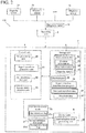
- the control unit 4 includes a pre-processing unit 40, a signal waveform generation unit 41, a first determination unit 42, and a second determination unit 43.
- the control unit 4 is configured to function as the pre-processing unit 40, the signal waveform generation unit 41, the first determination unit 42, and the second determination unit 43 by executing various programs stored in the storage unit 5.
- the control unit 4 includes, for example, a CPU (Central Processing Unit).
- the pre-processing unit 40 is configured to perform pre-processing of the magnetic signal 10. In this embodiment, the pre-processing unit 40 is configured to remove the high-frequency noise components of the magnetic signal 10.
- the pre-processing unit 40 includes, for example, a low-pass filter.
- the signal waveform generation unit 41 is configured to generate a signal waveform 11 (see FIG. 4 ) based on the magnetic signal 10 after the pre-processing. For more detailed information on the configuration in which the signal waveform generation unit 41 generates the signal waveform 11 will be described later.
- the first determination unit 42 is configured to output whether or not the magnetic body 90 has passed as a first determination result 20, based on the magnetic signal 10 of the magnetic sensor 1.
- the detailed configuration in which the first determination unit 42 outputs the first determination result 20 will be described later. Note that whether or not the magnetic body 90 has passed means whether or not the magnetic body 90 has passed the vicinity of the magnetic sensor 1. In other words, whether or not the magnetic body 90 has passed means whether or not the magnetic body 90 has entered the region 91.
- the second determination unit 43 is configured to output whether or not the magnetic body 90 has passed as a second determination result 21, after the output of the first determination result 20 by the first determination unit 42, based on the magnetic signal 10 of the magnetic sensor 1. Further, the second determination unit 43 is configured to have higher determination accuracy than the first determination unit 42. The detailed configuration in which the second determination unit 43 outputs the second determination result 21 will be described in later.
- the determination result processing unit 44 is configured to display whether or not the magnetic body 90 has passed on the display unit 6, based on the first determination result 20, the second determination result 21.
- the detailed configuration in which the determination result processing unit 44 displays whether or not the magnetic body 90 has passed on the display unit 6 will be described later.
- the storage unit 5 is configured to store the measurement data 22 acquired by the magnetic sensor 1.
- the measurement data 22 includes the position information 23 of the magnetic sensor 1, the time information 24 obtained the magnetic signal 10, and the magnetic signal 10.
- the storage unit 5 is configured to store various programs to be executed by the control unit 4, the signal detection determination program 25, a discriminator 26, standard waveform data 27, threshold data 28, and the like.
- the position information 23 of the magnetic sensor 1 denotes the information of the position where the magnetic sensor 1 is disposed in the region 91.
- the position information 23 includes the position coordinate where the magnetic sensor 1 is located.
- the storage unit 5 includes, for example, an HDD (Hard Disk Drive), a non-volatile memory, and the like.
- the display unit 6 includes a determination result processing unit 44.
- the display unit 6 is configured to display (output) the first determination result 20 and the second determination result 21.
- the display unit 6 includes, for example, a processing device (arithmetic unit), such as, e.g., a personal computer provided with a liquid crystal display, a CPU, a ROM (Read Only Memory), and a RAM (Random Access Memory).
- a processing device e.g., a personal computer provided with a liquid crystal display, a CPU, a ROM (Read Only Memory), and a RAM (Random Access Memory).
- the magnetic signal 10 acquired by the magnetic sensor 1 includes a signal 10a due to the magnetic body 90 (detection target) and a steady noise 10b. Specifically, the magnetic signal 10 can be expressed as the sum of the signal 10a caused by the magnetic body 90 and the steady noise 10b.
- the magnetic signal 10 acquired by the magnetic sensor 1 an example including a first peak 10c and a second peak 10d is shown. Note that in each of the graphs shown in FIG. 3 , the horizontal axis denotes the time, and the vertical axis denotes the signal intensity.
- the magnetic signal 10 includes the first peak 10c of a positive value and the second peak 10d of the negative value, but the magnetic signal 10 may include the first peak 10c of a negative value and the second peak 10d of a positive value.
- the signal waveform generation unit 41 is configured to generate a signal waveform 11 by delimiting the time-series magnetic signal 10 after a prescribed time 70 has elapsed by a predetermined time 71.
- the signal waveform generation unit 41 is configured to be able to generate signal waveforms 11 for various periods by changing the position to be delimited by the predetermined time 71.
- the signal waveform generation unit 41 is configured to initiate the generation of the signal waveform 11 based on the magnetic signal 10 and the threshold data 28. Specifically, the signal waveform generation unit 41 is configured to initiate the generation of the signal waveform 11 when the magnetic signal 10 exceeds the threshold.
- the example shown in FIG. 4 shows a signal waveform 11 in a state prior to the elapse of a predetermined time 71 after starting the generation of the signal waveform 11.
- the signal waveform generation unit 41 generates, after starting the generation of the signal waveform 11, a signal waveform 11 each time the magnetic signal 10 is acquired in accordance with a sampling period.
- the example shown in FIG. 4 is a signal waveform 11 in a state in which a part of the first peak 10c included in the magnetic signal 10 is included in the signal waveform 11.
- the example shown in FIG. 5 shows the entire waveform of the signal waveform 11 after the prescribed time 70 has elapsed.
- the prescribed time 70 since the prescribed time 70 has elapsed, all the peaks (the first peak 10c and the second peak 10d) included in the magnetic signal 10 are included in the signal waveform 11.
- the magnetic sensor 1 is configured to acquire a time-series magnetic signal 10 by the predetermined sampling period.
- the predetermined sampling duration is determined by the maximum value of the moving speed of the magnetic body 90, which is a detection target.
- the predetermined sampling period is set such that a value capable of reproducing the magnetic signal 10 having the same frequency as the frequency (the maximum frequency f) of the magnetic signal 10 acquired from the magnetic body 90 moving at the maximum value of the moving speed which is set as the detectable upper limit value is set as a sampling period based on the sampling theorem.
- the predetermined sampling period is a value greater than twice the maximum frequency f.
- the prescribed time 70 is determined based on the smallest value of the moving speed of the magnetic body 90, which is a detection target.
- the first determination unit 42 is configured to output the first determination result 20 by determining the magnetic signal 10 based on a predetermined condition. Specifically, the first determination unit 42 is configured to output the first determination result 20 using the signal detection determination program 25 stored in the storage unit 5.
- the first determination unit 42 is configured to output the first determination result 20 based at least in a part of the magnetic signal 10 after the prescribed time 70 has elapsed.
- the first determination unit 42 is configured to output the first determination result 20 based on at least a part of the magnetic signal 10 and the standard waveform data 27 stored in the storage unit 5 after the prescribed time 70 has elapsed.
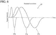
- FIG. 6 is a schematic diagram of the standard waveform data 27.
- the horizontal axis denotes the time
- the vertical axis denotes the signal intensity.
- the storage unit 5 stores, for example, first standard waveform data 27a, second standard waveform data 27b, and third standard waveform data 27c.
- the first standard waveform data 27a, the second standard waveform data 27b, and the third standard waveform data 27c are waveform data the same in the signal intensity and different in the period.
- the second standard waveform data 27b has a period smaller than that of the first standard waveform data 27a.
- the third standard waveform data 27c has a period larger than that of the first standard waveform data 27a.
- the first determination unit 42 is configured to sequentially output the first determination result 20 based on whether or not at least a part of the shape of the signal waveform 11 is a predetermined shape as a predetermined condition after the prescribed time 70 has elapsed. Specifically, the first determination unit 42 calculates the statistic, such as, e.g., the similarity degree of the shape between the standard waveform data 27 stored in the storage unit 5 and the signal waveform 11 and the change amount of the signal waveform 11. The first determination unit 42 is configured to output the first determination result 20 based on the calculated statistic and the threshold data 28.
- the first determination unit 42 is configured to output a first detection flag 20a as the first determination result 20.
- the first detection flag 20a is a value indicating whether or not the magnetic body 90 has passed. Specifically, the first detection flag 20a is a numerical value of 0 or 1. When detecting that the magnetic body 90 has passed, the first determination unit 42 outputs 1 as the first detection flag 20a. When not detecting that the magnetic body 90 has passed, the first determination unit 42 outputs 0 as the first detection flag 20a.
- the second determination unit 43 is configured to output the second determination result 21 based on the discriminator 26 trained by machine learning.
- the discriminator 26 trained by machine learning.
- a neural network, a support vector machine, or the like is used as the way of training the discriminator 26 .
- the discriminator 26 has been trained using a simulation waveform generated by simulating the magnetic signal 10 emitted from the magnetic body 90 and the measured noise waveform.
- the simulation waveform is used for learning with the noise waveforms superimposed.
- the simulation waveform is waveform data exhaustively generated by setting a plurality of parameters to various values.
- the multiple parameters include, for example, the transverse magnetism of the magnetic body 90, the fore-and-aft direction magnetism of the magnetic body 90, the perpendicular magnetism of the magnetic body 90, the traveling direction of the magnetic body 90, the traveling speed of the magnetic body 90, the underwater depth of the magnetic body 90, the transverse distance (distance in the transverse direction), etc.
- the simulation waveform is generated by simulating the waveform of the magnetic signal 10 when the magnetic body 90 has completely passed.
- the second determination unit 43 is configured to output the second determination result 21 based on the magnetic signal 10 after the prescribed time 70 has elapsed. Specifically, the second determination unit 43 is configured to output the second determination result 21 after the prescribed time 70 has elapsed, based on the entire waveform of the signal waveform 11 (see FIG. 5 ). The second determination unit 43 is configured to output the second determination result 21 based on the signal waveform 11 and the discriminator 26. Specifically, the second determination unit 43 outputs the second determination result 21 based on the accuracy of whether or not the magnetic body 90 has passed output by the discriminator 26 and the threshold data 28. Note that the accuracy of whether or not the magnetic body 90 has passed is a value indicating that the magnetic signal 10 is a signal caused by the passage of the magnetic body 90. Specifically, the accuracy of whether or not the magnetic body 90 has passed is a number between 0 and 1, which means that the closer it is to 1, the higher the probability that the magnetic signal 10 is the signal resulting from the passage of the magnetic body 90.
- the second determination unit 43 is configured to output a second detection flag 21a as the second determination result 21.
- the second detection flag 21a is a value indicating whether or not the magnetic body 90 has passed. Specifically, the second detection flag 21a is a numerical value of 0 or 1. When detecting that the magnetic body 90 has passed, the second determination unit 43 outputs 1 as the second detection flag 21a. When not detecting that the magnetic body 90 has passed, the second determination unit 43 outputs 0 as the second detection flag 21a.
- the determination result processing unit 44 is configured to make the display unit 6 display whether or not the magnetic body 90 has passed, based on the first detection flag 20a and the second detection flag 21a.
- FIG. 7 is a schematic view of the display unit 6 on which the first determination result 20 and the second determination result 21 are displayed.
- a first display area 60 and a second display area 61 are displayed on the display unit 6.
- the first display area 60 is an area in which the first determination result 20 is displayed.
- the second display area 61 is an area in which the second determination result 21 is displayed.
- the determination result processing unit 44 is configured to make the display unit 6 display whether or not the magnetic body 90 has passed in the region 91 based on the first determination result 20, the second determination result 21, and the position information 23 of the magnetic sensor 1. Specifically, as shown in FIG. 7 , in the first display area 60, a map of the region 91 in which a plurality of magnetic sensors 1 is disposed is displayed. The determination result processing unit 44 illustrates a plurality of icons 30 each indicating the magnetic sensor 1 on the map, based on the position information 23 of each magnetic sensor 1.
- the first display area 60 includes a first icon 30a, a second icon 30b, a third icon 30c, a fourth icon 30d, a fifth icon 30e, a sixth icon 30f, a seventh icon 30g, and an eighth icon 30h.
- the determination result processing unit 44 is configured to display whether or not the magnetic body 90 has passed by the display unit 6 by the change of the display mode, based on the first detection flag 20a and the second detection flag 21a.
- the determination result processing unit 44 changes the color of the icon 30 displayed in the first display area 60 to indicate whether or not the magnetic body 90 has passed.
- the change in the display mode (the change in the color of the icon 30) is illustrated by the presence or absence of hatching.
- the change of the display mode (the change of the color of the icon 30) is illustrated by changing the hatching according to the values of the first detection flag 20a and the second detection flag 21a.
- the display mode of the sixth icon 30f and the display mode of the seventh icon 30g are changed.
- the monitoring person can determine that the magnetic body 90 is passing between the sixth magnetic sensor 1f and the seventh magnetic sensor 1g.
- the second display area 61 displays a table 64 including a column 62 for displaying IDs allocated to the respective magnetic sensors 1 and a column 63 for displaying whether or not the magnetic body 90 has passed.
- a column 62 for displaying IDs allocated to the respective magnetic sensors 1 and a column 63 for displaying whether or not the magnetic body 90 has passed.
- 1 to 8 are displayed as IDs of the magnetic sensors 1.
- the determination result processing unit 44 is configured to display the time information 24 about the completion of the passage of the magnetic body 90 on the display unit 6 when the second detection flag 21a is 1. Further, the determination result processing unit 44 is configured to display the time information 24 about the completion of the passage of the magnetic body 90 by the display unit 6. In this embodiment, the determination result processing unit 44 is configured to indicate how many minutes has elapsed after the completion of the passage of the magnetic body 90 as the time information 24.
- the determination accuracy of the second determination unit 43 is configured to be higher than the determination accuracy of the first determination unit 42.
- the second determination unit 43 is configured to be higher in the determination accuracy than the determination accuracy of the first determination unit 42 by performing the determination using the discriminator 26 trained to be higher in the determination accuracy than the first determination unit 42. Therefore, the passage of the magnetic body 90 that cannot be detected by the first determination unit 42 can be detected by the second determination unit 43. In the example of the embodiment shown in FIG. 7 , it is detected by the second determination unit 43 that the magnetic body 90 has passed the vicinity of the first magnetic sensor 1a.
- the second display area 61 is provided with a start button 80 and a stop button 81.
- the start button 80 is configured to be operable to initiate the detection of the passage of the magnetic body 90.
- the stop button 81 is configured to accept an operation of stopping the detection of the passage of the magnetic body 90.
- the magnetic detection system 100 starts to detect whether or not the magnetic body 90 has passed. Further, when the monitoring person presses the stop button 81, the detection of whether or not the magnetic body 90 has passed by the magnetic detection system 100 is stopped.
- Step 101 the control unit 4 determines whether or not the start button 80 has been pressed. When the start button 80 has not been pressed, the process of Step 101 is repeated. When the start button 80 is pressed, the process proceeds to Step 102.
- Step 102 the control unit 4 acquires the magnetic signal 10 from the magnetic sensor 1 through the receiving unit 2.
- Step 102 the control unit 4 acquires the position information 23 of the magnetic sensor 1 and the time information 24 when the magnetic signal 10 is obtained.
- the pre-processing unit 40 performs pre-processing for the magnetic signal 10. Specifically, the pre-processing unit 40 performs, with respect to the magnetic signal 10, the geomagnetic orthogonal coordinate transformation processing, the background magnetic field compensating processing, the total magnetic force calculation processing, the low-pass filter processing, and the high-pass filter processing.
- the geomagnetic orthogonal coordinate transformation processing is a process of unifying the posture (direction) that each magnetic sensor 1 is placed by converting in one direction.
- the background magnetic field compensation processing is a process of acquiring only the magnetic variation due to the magnetic body 90 by placing a compensation sensor (not shown) for acquiring the ambient environmental noise at a place where it is less susceptible to the magnetic body 90 and removing the environmental noise acquired by the compensation sensor from the magnetic signal 10 of the respective magnetic sensors 1.
- the total magnetic force calculation processing is a process of obtaining the total magnetic force obtained by synthesizing the magnetic forces in the three axial directions of the vertical direction (Z-direction) and two directions (X-direction and Y-direction) perpendicular to each other in a plane perpendicular to the Z-direction.
- the low-pass filter processing is a process of removing high-frequency noise components from the magnetic signal 10 by applying a low-pass filter to the magnetic signal 10.
- the high-pass filter processing is a process of removing DC components from the magnetic signal 10 by applying a high-pass filter to the magnetic signal 10.
- Step 102 the control unit 4 performs control for storing the magnetic signal 10 in the storage unit 5.
- the control unit 4 performs control to store the magnetic signal 10, the position information 23, and the time information 24 in the storage unit 5 as measurement data 22.
- Step 103 the signal waveform generation unit 41 determines whether or not the magnetic signal 10 has exceeded the threshold. When the magnetic signal 10 has exceeded the threshold, the process proceeds to Step 104. When the magnetic signal 10 has not exceeded the threshold, the process proceeds to Step 102.
- Step 104 the signal waveform generation unit 41 generates a signal waveform 11 based on the magnetic signal 10 stored in the storage unit 5.
- Step 105 the control unit 4 determines whether or not the prescribed time 70 has elapsed. When the prescribed time 70 has elapsed, the process proceeds to Step 106 and Step 108. When the prescribed time 70 has not elapsed, the process repeats the process of Step 105.
- the first determination unit 42 performs the first determination processing.
- the first determination unit 42 acquires the first detection flag 20a as the first determination process. Specifically, the first determination unit 42 acquires the first detection flag 20a based on the signal waveform 11 and the standard waveform data 27.
- Step 107 the first determination unit 42 outputs the acquired first detection flag 20a to the determination result processing unit 44.
- Step 108 the second determination unit 43 performs the second determination process.
- the second determination unit 43 acquires the second detection flag 21a as the second determination processing. Specifically, the second determination unit 43 acquires the second detection flag 21a based on the signal waveform 11 and the discriminator 26.
- Step 109 the second determination unit 43 outputs the acquired second detection flag 21a to the determination result processing unit 44.
- Step 110 the determination result processing unit 44 displays whether or not the magnetic body 90 has passed on the display unit 6 by changing the display mode based on the first detection flag 20a and the second detection flag 21a.
- Step 111 the control unit 4 determines whether or not the stop button 81 has been pressed. When the stop button 81 has not been pressed, the process proceeds to Step 102. When the stop button 81 is pressed, the process ends.
- the first determination process and the second determination process by the first determination unit 42 and the second determination unit 43 are sequentially performed every predetermined sampling period after the prescribed time 70 has elapsed since the generation of the signal waveform 11 was started.
- the first determination result 20 (first detection flag 20a) is also displayed every predetermined sampling period. That is, the first determination process by the first determination unit 42, the display of the first determination result 20 (first detection flag 20a), the second determination processing by the second determination unit 43, and the display of the second determination result 21 (second detection flag 21a) are performed as parallel processing.
- the magnetic detection system 100 is provided with: the magnetic sensor 1 configured to be installed underwater to acquire the magnetic signal 10; the storage unit 5 configured to store the magnetic signal 10 acquired by the magnetic sensor 1; the first determination unit 42 configured to output whether or not a magnetic body 90 has passed as the first determination result 20 based on the magnetic signal 10 of the magnetic sensor 1; the second determination unit 43 configured to output whether or not the magnetic body 90 has passed as the second determination result 21 based on the magnetic signal 10 of the magnetic sensor 1 after an output of the first determination result 20 by the first determination unit 42; and the display unit 6 configured to display (output) the first determination result 20 and the second determination result 21, wherein the second determination unit 43 is configured to have higher determination accuracy than the first determination unit 42.
- the first determination result 20 and the second determination result 21, which differ in the output timing and the determination accuracy, are displayed (output), so that the monitoring person can determine whether or not the magnetic body 90 has passed based on the first determination result 20, which is earlier in the output timing, and the second determination result 21, which is higher in the determination accuracy than the first determination result 20. Further, since the first determination result 20 and the second determination result 21 indicating whether or not the magnetic body 90 has passed are outputted. Therefore, as compared with the configuration in which the monitoring person confirms whether or not it is a magnetic signal 10 due to the magnetic body 90 by directly confirming the magnetic signal 10, it is possible to reduce the burden on the monitoring person. Consequently, it is possible to provide the magnetic detection system 100 capable of reducing the burden on the monitoring person while ensuring immediacy and determination accuracy.
- the first determination unit 42 is configured to output the first determination result 20 by discriminating the magnetic signal 10 based on the predetermined condition
- the second determination unit 43 is configured to output the second determination result 21 based on the discriminator 26 trainged by machine learning.
- the second determination unit 43 having higher determination accuracy than the first determination unit 42 can be easily provided.
- the magnetic sensor 1 is configured to acquire the time-series magnetic signal 10 with the predetermined sampling period.
- the first determination unit 42 is configured to output the first determination result 20 based on at least a part of the magnetic signal 10 after the prescribed time 70 has elapsed.
- the second determination unit 43 is configured to output the second determination result 21 based on the magnetic signal 10 after the prescribed time 70 has elapsed.
- the first determination result 20 is output based on the part of the magnetic signal 10, it is possible to output a highly immediate result.
- the second determination result 21 is output based on the magnetic signal 10 after the prescribed time 70 has elapsed, it is possible to output a highly reliable result. As a result, the immediacy can be ensured by the first determination result 20, and the determination accuracy can be ensured by the second determination result 21.
- the magnetic detection system further includes: the signal waveform generation unit 41 configured to generate the signal waveform 11 by delimiting the time-series magnetic signal 10 by the prescribed time 70.
- the first determination unit 42 is configured to sequentially output the first determination result 20 based on whether or not at least the part of the shape of the signal waveform 11 is a predetermined shape as the predetermined condition after the prescribed time has elapsed.
- the second determination unit 43 is configured to output the second determination result 21 based on the entire waveform of the signal waveform 11 after the prescribed time has elapsed.
- the system further includes: the determination result processing unit 44 for notifying the display unit 6 (notification unit) of whether or not the magnetic body 90 has passed based on the first determination result 20 and the second determination result 21.
- the first determination unit 42 is configured to output, as the first determination result 20, the first detection flag 20a which is a value indicating whether or not the magnetic body 90 has passed.
- the second determination unit 43 is configured to output, as the second determination result 21, the second detection flag 21a which is a value indicating whether or not the magnetic body 90 has passed.
- the determination result processing unit 44 is configured to display (notify) whether or not the magnetic body 90 has passed by the display unit 6 based on the first detection flag 20a and the second detection flag 21a.
- the determination result processing unit 44 is configured to display (notify) whether or not the magnetic body 90 has passed by the display unit 6 according to the change of the notification mode based on the first detection flag 20a and the second detection flag 21a.
- the change of the first detection flag 20a with high immediacy can be easily visually grasped in real-time, and the passing time of the magnetic body 90 can be grasped based on the second detection flag 21a with high certainty. As a result, it is possible to more accurately determine whether or not the magnetic body 90 has passed, regardless of the proficiency of the monitoring person.
- a plurality of the magnetic sensors 1 is installed in the region 91 for detecting the passage of the magnetic body 90.
- the determination result processing unit 44 is configured to make the display unit 6 display (notify) whether or not the magnetic body 90 has passed in the region 91 based on the first determination result 20 and the second determination result 21, and the position information 23 of the magnetic sensor 1.
- the monitoring person can visually grasp whether or not the magnetic body 90 has passed and the position at which the magnetic body 90 is passing.
- the notification unit includes the display unit 6 that displays the first determination result 20 and the second determination result 21 on the same screen.
- the first determination result 20 and the second determination result 21 can be grasped at the same time.
- the first determination result 20 having immediacy and the second determination result 21 having higher determination accuracy can be grasped at a time. Therefore, the convenience of the monitoring person can be improved.
- the predetermined sampling period is determined based on the maximum value of the moving speed of the magnetic body 90, which is a detection target, and the prescribed time 70 is determined based on the minimum value of the moving speed.
- the present invention is not limited thereto.
- the magnetic detection system 200 may be configured such that in the first display area 60, the magnetic sensor 1, and the land 92 (see FIG. 10 ) and the sea 93 are displayed on the map 94 in a distinguishable manner.
- the magnetic detection system 200 according to the first modification differs from the magnetic detection system 100 according to the above-described embodiment in that it includes a control unit 14 instead of the control unit 4.
- the control unit 14 in the first display area 60, is configured to display a map 94 which shows the land 92 and the sea 93 in a distinguishable manner.
- the control unit 14 is configured to display the magnetic sensor 1 in the map 94 which shows the land 92 and the sea 93 distinguishably.
- the magnetic sensors 1 are installed in the region of the sea 93 on the map. With this configuration, since the magnetic sensor 1 is displayed on the map 94 in which the land 92 and the sea 93 are displayed, the user can easily grasp the positional relation between the position of the magnetic sensor 1 and the land 92. As a result, the user can easily grasp the moving condition of the magnetic body 90 approaching the land 92.
- the control unit 14 is configured to display the sensor number 12 (see FIG. 9 ) unique for each magnetic sensor 1 so as to be superimposed on the magnetic sensor 1 when the magnetic sensor 1 is displayed in the first display area 60.
- the sensor number 12 is shown in FIG. 10 . That is, the number, such as, e.g., "001" and "002" displayed inside the magnetic sensor 1, is the sensor number 12.
- the magnetic sensor 1 unique for each sensor number 12 is displayed, in the second display area 61, when displaying whether or not the magnetic body 90 has passed, by displaying the sensor number 12 together, the position of the magnetic sensor 1 and the detection result by the magnetic sensor 1 can be displayed in association by the sensor number 12.
- the user can easily grasp the respective magnetic sensors 1 displayed on the first display area 60 and the information of whether or not the magnetic body 90 displayed in the second display area 61 has passed in an associated manner. Therefore, the user can more easily grasp whether or not the magnetic body 90 has passed.
- the control unit 14 is configured to store the position information of the sensor. Specifically, the control unit 14 is configured to store the position information 23 (see FIG. 9 ) of the position where the sensor is installed in association with the sensor number 12. Specifically, when placing the magnetic sensor 1, the latitude and the longitude of the point where the magnetic sensor 1 is placed are obtained by a GPS (Global Positioning System) or the like, and the latitude and the longitude obtained are stored in association with the sensor number 12.
- GPS Global Positioning System
- control unit 14 is configured to display the magnetic sensor 1 based on the stored position information 23 and the sensor number 12, in the map 94 of the first display area 60 in a state in which the sensor number 12 is superimposed on the position coordinate corresponding to the position information 23.
- the control unit 14 is configured to display whether or not the magnetic body 90 has passed in time series on the basis of the first determination result 20 (see FIG. 9 ) and the second determination result 21 (see FIG. 9 ).
- the control unit 14 is configured to display the table 66 showing whether or not the magnetic body 90 has passed in time series in the second display area 61.
- the table 66 includes a column 67 for displaying the time when the magnetic signal 10 emitted from the magnetic body 90 begins to be detected, a column 68 for displaying the time when the detection of the magnetic signal 10 emitted from the magnetic body 90 is completed, and a column 69 for displaying the sensor number 12 of the magnetic sensor 1.
- the control unit 14 updates the table 66 every time the first determination result 20 and the second determination result 21 are output, and displays whether or not the magnetic body 90 has passed in time series. With this configuration, since whether or not the magnetic body 90 has passed is displayed in time series, by confirming the sensor number 12 together with the determination result, it is possible to easily grasp the moving path of the magnetic body 90.
- control unit 14 is configured to be able to select a criterion for displaying the determination result.
- the control unit 14 is configured to display the criterion selection section 65 on the second display area 61.
- the control unit 14 displays, as the criterion selection section 65, a real-time analysis option 65a, an AI analysis option 65b, and a combination analysis option 65c.
- the control unit 14 displays only the first determination result 20.
- the control unit 14 displays only the second determination result 21.
- the control unit 14 is configured to display both the first determination result 20 and the second determination result 21.
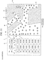
- control unit 14 is configured such that the position information 23 of the magnetic sensor 1 can be changed. As shown in FIG. 10 , the control unit 14 is configured to display an area setting button 83 in the display unit 6. When the area setting button 83 is pressed by the user, the control unit 14 displays an area setting mode screen (image) on the second display area 61 as shown in FIG. 11 .
- the control unit 14 displays a table 71 and a setting field 72 in the second display area 61 as an area setting mode.
- the table 71 includes a column 73 showing the sensor number 12 of the magnetic sensor 1, a column 74 for displaying the latitude where the magnetic sensor 1 is placed, and a column 75 for displaying the longitude where the magnetic sensor 1 is placed.
- a field 76 for displaying the sensor number 12 of the magnetic sensor 1 a latitude input field 77, a longitude input field 78, and a setting button 84 are displayed. In the example shown in FIG.
- the number of the position information 23 of the magnetic sensor 1 displayed in the table 71 is illustrated as seven, but seven or more position information 23 of the magnetic sensor 1 may be displayed. In this case, the table 71 may be displayed so as to be scrollable.
- the sensor number 12 of the magnetic sensor 1 selected by the user among the magnetic sensors 1 displayed in the table 71 is displayed in the column 76.
- the position information 23 (latitude and longitude) of the magnetic sensor 1 selected by the user is displayed in the latitude input field 77 and the longitude input field 78. Note that it may be configured such that among the magnetic sensors 1 on the map 94 displayed in the first display area 60, the sensor number 12 and the position information 23 of the magnetic sensor 1 selected by the user are displayed in the setting field 72.
- the user selects the magnetic sensor 1 in which the underwater position is actually moved, inputs the position information 23 (latitude and longitude) after the movement, and presses the setting button 84.
- the control unit 14 updates the latitude and the longitude of the table 71 in accordance with the values input to the latitude input field 77 and the longitude input field 78.
- the control unit 14 displays the OK button 85 and the cancel button 86 on the outer side of the first display area 60.
- the control unit 14 stores the position information 23 of the respective magnetic sensors 1 set by the user in the storage unit 5. That is, the position information 23 of the magnetic sensor 1 is updated with the latitude and the longitude values of the updated table 71. Thereafter, the control unit 14 returns the display unit 6 to the state shown in FIG. 10 . Further, when the cancel button 86 is pressed, the control unit 14, without updating the position information 23 of the respective magnetic sensors 1, the display unit 6 is returned to the state shown in FIG. 10 . With this configuration, it is possible to update the position information 23 of the magnetic sensor 1 individually. As a result, the usability of the user can be improved.
- the map 94 displayed on the first display area 60 is configured to enlarge and display a part of the area.
- the control unit 14 is configured to display the marker indicating the direction of the land 92 when the land 92 (see FIG. 10 ) is not displayed when the first display area 60 is displayed in an enlarged manner.
- the control unit 14 is configured to display the marker indicating the direction of the land 92 when the magnetic sensor 1 is enlarged so that the land 92 does not appear (only the region of the sea 93 is displayed) on the map 94. Note that as shown in FIG.
- the marker 12 may be configured such that when the land 92 is located in different directions in the magnetic sensor 1, a plurality of markers, i.e., the marker 79a and the marker 79b, is displayed as markers indicating the direction of the land 92.
- the marker 79a and the marker 79b indicate the directions of the land 92 in different directions.
- the control unit 14 may be configured to display the difference in the distance to the land 92 by differentiating the display modes of the marker 79a and the marker 79b from each other according to the distance to the land 92.
- the marker 79a and the marker 79b are different in the display move by using different hatchings.
- the region 95 in FIG. 10 is enlarged.
- the first determination unit 42 outputs the acquired first determination result 20 based on the predetermined condition
- the second determination unit 43 outputs the second determination result 21 based on the discriminator 26 trained by machine learning
- the present invention is not limited thereto.
- each of the first determination unit 142 and the second determination unit 143 may be configured to output the first determination result 20 and the second determination result 21 according to the discriminator trained by machine learning.
- the magnetic detection system 300 according to the second modification differs from the magnetic detection system 100 according to the above-described embodiment in that it includes: a first determination unit 142 instead of the first determination unit 42; and a second determination unit 143 instead of the second determination unit 43.
- the first determination unit 142 according to the second modification is configured to output the first determination result 20 based on the first discriminator 260.
- the first determination unit 142 outputs the first detection flag 20a as the first determination result 20.
- the second determination unit 143 according to the second modification is configured to output the second determination result 21 based on the second discriminator 261.
- the second determination unit 143 outputs the second detection flag 21a as the second determination result 21. Since the configuration in which the first determination unit 142 outputs the first detection flag 20a and the configuration in which the second determination unit 143 outputs the second detection flag 21a are the same as the configuration in which the second determination unit 43 of the above-described embodiment outputs the second detection flag 21a. Therefore, the detailed descriptions thereof are omitted.
- the first discriminator 260 and the second discriminator 261 are stored in the storage unit 5.
- the first discriminator 260 is a discriminator trained by machine learning.
- the second discriminator 261 is a discriminator trained by machine learning that differs from the first discriminator 260.
- the different machine learning means machine learning that differs in at least one of a method of machine learning and a condition.
- the second discriminator 261 is a discriminator trained by machine learning that can determine the magnetic signal 10, which cannot be determined by the first discriminator 260, as the machine learning that differs from the first discriminator 260.
- the first determination unit 142 is configured to output the first determination result 20 based on the first discriminator 260 trained by machine learning
- the second determination unit 143 is configured to output the second determination result 21 based on the second discriminator 261 trained by machine learning that differs from the first discriminator 260.
- the first determination unit 142 and the second determination unit 143 can compensate for each other.
- the second determination unit 43 outputs the second determination result 21 based on the discriminator 26 trained by machine learning, but the present invention is not limited thereto.
- the second determination unit 43 may be configured to output the second determination result 21 based on a predetermined condition.
- the predetermined condition needs to be set in more detail in order to make the determination accuracy of the second determination unit 43 higher than the determination accuracy of the first determination unit 42, which increases the designing costs. Therefore, it is preferable that second determination unit 43 have a configuration in which the second determination result 21 is output based on the discriminator 26
- the first determination unit 42 outputs the first determination result 20 using at least a part of the magnetic signal 10 within the predetermined time 71, but the present invention is not limited thereto.
- the first determination unit 42 may be configured to output the first determination result 20 using the entire waveform of the magnetic signal 10 at a predetermined time 71.
- the first determination unit 42 is configured to output the first determination result 20 using the entire waveform of the magnetic signal 10 at the predetermined time 71, the determination accuracy is improved, but the immediacy is reduced. Therefore, it is preferable that the first determination unit 42 output the first determination result 20 using at least a part of the magnetic signal 10 within the predetermined time 71.
- the second determination unit 43 outputs the second determination result 21 using the entire waveform of the magnetic signal 10 at the predetermined time 71, but the present invention is not limited thereto.
- the second determination unit 43 may be configured to output the second determination result 21 using a part of the magnetic signal 10 within the predetermined time 71.
- the discriminator 26 may be trained using a simulation waveform in which the magnetic body 90 is passing.
- the second determination unit 43 is configured to output the second determination result 21 using a part of the magnetic signal 10 within a predetermined time 71, the immediacy is improved, but the determination accuracy is reduced. Therefore, it is preferable that the second determination unit 43 output the second determination result 21 by using the entire waveform of the magnetic signal 10 at the predetermined time 71.
- the second determination unit 43 outputs the second detection flag 21a, but the present invention is not limited to this.
- the second determination unit 43 may be configured to output the second determination result 21 other than the second detection flag 21a.
- the second determination unit 43 may be configured to output, as the second determination result 21, a message, such as, e.g., "Passage Completed", indicating that the passage of the magnetic body 90 has been completed.
- the determination result processing unit 44 displayed, as the time information 24 to be displayed together with the second determination result 21, the number of minutes prior to the completion of the passage of the magnetic body 90, but the present invention is not limited thereto.
- the determination result processing unit 44 may be configured to indicate, as the time information 24, the time at which the passage of the magnetic body 90 is completed.
- the number of magnetic sensors 1 may be greater than 8 or less than 8.
- the number of magnetic sensors 1 may be set to match the region 91 in which the passage of the magnetic body 90 is desired.
- the first determination result 20 and the second determination result 21 are displayed on the display unit 6 on the same screen, but the present invention is not limited thereto.
- the first determination result 20 and the second determination result 21 may not be displayed on the same screen.
- the predetermined sampling period is determined based on the maximum value of the moving speed of the magnetic body 90, but the present invention is not limited thereto.
- the predetermined sampling period may be determined based on the average value of the moving speed of the magnetic body 90.
- the predetermined sampling period may be set for each moving speed of the magnetic body 90. That is, the magnetic sensor 1 may be configured to acquire the magnetic signal 10 based on a plurality of sampling periods.
- the prescribed time 70 is determined based on the lowest moving speed of the magnetic body 90, but the present invention is not limited thereto.
- the prescribed time 70 may be determined based on the average value of the moving speed of the magnetic body 90.
- the prescribed time 70 may be set for each moving speed of the magnetic body 90.
- the magnetic sensor 1 may be configured to acquire the magnetic signal 10 based on the prescribed time 70.
- the standard waveform data 27 an example is shown in which three waveform data is used, the present invention is not limited thereto.
- the standard waveform data 27 may be more or less than three.
- the magnetic detection system 100 a plurality of magnetic sensors 1 is wired to the computer 3 via the receiving unit 2, the present invention is not limited thereto.
- the magnetic sensor 1, the receiving unit 2, and the computer 3 may be wirelessly connected.
- the notification unit is constituted by the display unit 6 for displaying the first determination result 20 and the second determination result 21, but the present invention is not limited thereto.
- the notification unit may be composed of a buzzer that emits a warning sound or a lamp that emits warning light.
- the fluxgate type magnetic sensor 1 is used, but the present invention is not limited to this. Any type of magnetic sensor may be used in the present invention.
- an MR (Magneto Resistive) sensor, an MI (Magneto Impedance element) sensor, or the like may be used as the magnetic sensor 1.
- a magnetic detection system including:
- the magnetic detection system as recited in the above-described Item 1, wherein the first determination unit is configured to output the first determination result by determining the magnetic signal based on a predetermined condition, and wherein the second determination unit is configured to output the second determination result based on a discriminator trained by machine learning.
- the magnetic detection system as recited in the above-described Item 2, wherein the magnetic sensor is configured to acquire a time-series magnetic signal by a predetermined sampling period, wherein the first determination unit is configured to output the first determination result based on at least a part of the magnetic signal after a prescribed time has elapsed, and wherein the second determination unit is configured to output the second determination result based on the magnetic signal after the prescribed time has elapsed.
- the magnetic detection system as recited in the above-described Item 1, wherein the first determination unit is configured to output the first determination result based on a first discriminator trained by machine learning, and wherein the second determination unit is configured to output the second determination result based on a second discriminator trained by machine learning, the second discriminator being different from the first discriminator.
- the magnetic detection system as recited in the above-described Item 6, wherein the determination result processing unit is configured to make the notification unit notify that whether or not whether or not the magnetic body has passed by a change in a notification mode based on the first detection flag and the second detection flag.
- the magnetic detection system as recited in the above-described Item 6 or 7, wherein a plurality of the magnetic sensors is arranged in a region for detecting a passage of the magnetic body, and wherein the determination result processing unit is configured to make the notification unit notify that whether or not the magnetic body has passed in the region, based on the first determination result, the second determination result, and position information of the magnetic sensor.
- the notification unit includes a display unit for displaying the first determination result and the second determination result on a same screen.
- the magnetic detection system as recited in any one of the above-described Items 2 to 9, wherein the predetermined sampling period is determined based on a maximal value of a moving speed of the magnetic body that is the detection target, and wherein the prescribed time is determined based on a minimum value of the moving speed.
Landscapes
- Physics & Mathematics (AREA)
- Engineering & Computer Science (AREA)
- General Physics & Mathematics (AREA)
- Theoretical Computer Science (AREA)
- Software Systems (AREA)
- Remote Sensing (AREA)
- Evolutionary Computation (AREA)
- Life Sciences & Earth Sciences (AREA)
- Data Mining & Analysis (AREA)
- Computing Systems (AREA)
- General Engineering & Computer Science (AREA)
- Mathematical Physics (AREA)
- Computer Vision & Pattern Recognition (AREA)
- Artificial Intelligence (AREA)
- Condensed Matter Physics & Semiconductors (AREA)
- Medical Informatics (AREA)
- Environmental & Geological Engineering (AREA)
- Geology (AREA)
- General Life Sciences & Earth Sciences (AREA)
- Geophysics (AREA)
- Electromagnetism (AREA)
- Acoustics & Sound (AREA)
- Mechanical Engineering (AREA)
- Ocean & Marine Engineering (AREA)
- Geophysics And Detection Of Objects (AREA)
- Measuring Magnetic Variables (AREA)
Abstract
Description
- The priority application number
JP2020-036104 - The present invention relates to a magnetic detection system, and more specifically to a magnetic body detection system equipped with a magnetic sensor for detecting a magnetic body.
- Conventionally, a magnetic detection system is known in which a magnetic sensor is equipped to detect a magnetic body. Such a magnetic detection system is disclosed, for example, in Japanese Unexamined Patent Application Publication No.
2013-156225 - Japanese Unexamined Patent Application Publication No.
2013-156225 2013-156225 - The magnetic sensor is installed underwater. The calculation unit is configured to perform an operation on the approximation degree of the magnetic waveform measured by the magnetic sensor and the predictable noise fluctuation. Further, the calculation unit is configured to perform an operation on the approximation degree of the magnetic waveform measured by the magnetic sensor and the theoretical standard waveform caused by the magnetic body. The determination unit is configured to perform a determination relating to the detection of the magnetic signal, based on the calculation result of the arithmetic unit.
- Here, in the magnetic detection system as disclosed in Japanese Unexamined Patent Application Publication No.
2013-156225 - The present invention has been made to solve the above-described problems, and an object of the present invention is to provide a magnetic detection system capable of reducing a burden on a monitoring person while ensuring immediacy and determination accuracy.
- In order to achieve the above-described object, a magnetic detection system according to one aspect of the present invention includes:
- a magnetic sensor configured to be installed underwater to acquire a magnetic signal;
- a storage unit configured to store the magnetic signal acquired by the magnetic sensor;
- a first determination unit configured to output whether or not a magnetic body has passed as a first determination result based on the magnetic signal of the magnetic sensor;
- a second determination unit configured to output whether or not the magnetic body has passed as a second determination result based on the magnetic signal of the magnetic sensor after an output of the first determination result by the first determination unit; and
- a notification unit configured to output the first determination result and the second determination result,
- wherein the second determination unit is configured to have higher determination accuracy than the first determination unit.
- In the magnetic detection system according to the first aspect of the present invention, by configuring as described above, the first determination result and the second determination result that differ from each other in the output timing and the determination accuracy are notified. Therefore, the monitoring person can determine whether or not a magnetic body has passed, based on the first determination result earlier in the output timing and the second determination result higher in the determination accuracy than the first determination result. Further, the first determination result and the second determination result, which indicate whether or not the magnetic body has passed, are outputted. Therefore, the burden on the monitoring person can be reduced, as compared with the configuration in which the monitoring person determines whether or not it is a magnetic signal caused by a magnetic body by directly confirming the magnetic signal. Consequently, it is possible to provide a magnetic detection system capable of reducing the burden on the monitoring person while ensuring immediacy and determination accuracy.
-
-
FIG. 1 is a schematic diagram showing an entire configuration of a magnetic detection system according to one embodiment. -
FIG. 2 is a block diagram illustrating a configuration of a magnetic detection system according to one embodiment. -
FIG. 3 is a schematic diagram of a magnetic signal obtained by a magnetic detection system according to one embodiment. -
FIG. 4 is a schematic diagram of a signal waveform based on a part of a magnetic signal generated by a signal waveform generation unit. -
FIG. 5 is a schematic diagram of an entire waveform of a signal waveform generated by a signal waveform generation unit. -
FIG. 6 is a schematic diagram of a standard waveform used for a magnetic detection system according to one embodiment. -
FIG. 7 is a schematic diagram of a determination result displayed on a display unit of a magnetic detection system according to an embodiment. -
FIG. 8 is a flowchart illustrating a process for displaying a first determination result and a second determination result. -
FIG. 9 is a block diagram showing a configuration of a magnetic detection system according to a first modification. -
FIG. 10 is a schematic diagram of a determination result displayed on a display unit of a magnetic detection system according to the first modification. -
FIG. 11 is a schematic diagram of an area setting window displayed on a display unit of a magnetic detection system according to the first modification. -
FIG. 12 is a schematic view showing an enlarged partial area of a first display area in a display unit of a magnetic detection system according to the first modification. -
FIG. 13 is a block diagram showing a configuration of a magnetic detection system according to a second modification. - Hereinafter, some embodiments in which the present invention is embodied will be described with reference to the attached drawings.
- Referring to
FIG. 1 to FIG. 7 , a configuration of amagnetic detection system 100 according to an embodiment will be described. - The
magnetic detection system 100 according to this embodiment is provided with, as shown inFIG. 1 , amagnetic sensor 1, areceiving unit 2, and acomputer 3. Themagnetic detection system 100 of this embodiment detects whether or not themagnetic body 90 has passed by detecting amagnetic signal 10 emitted from themagnetic body 90. Based on the detection result output by themagnetic detection system 100, the monitoring person can recognize whether or not themagnetic body 90 has passed and can consider the countermeasures in accordance with whether or not themagnetic body 90 has passed. Themagnetic sensor 1 is installed, for example, in ports and harbors. Themagnetic body 90 sensed by themagnetic detection system 100 includes, for example, a vessel or the like. - The
magnetic sensor 1 is installed underwater. In this embodiment, a plurality of themagnetic sensors 1 for detecting the passage of themagnetic body 90 is installed in theregion 91. Themagnetic sensor 1 includes, for example, a firstmagnetic sensor 1a, a secondmagnetic sensor 1b, a thirdmagnetic sensor 1c, a fourthmagnetic sensor 1d, a fifthmagnetic sensor 1e, a sixthmagnetic sensor 1f, a seventh magnetic sensor 1g, and an eighthmagnetic sensor 1h. The plurality ofmagnetic sensors 1 is spaced apart from each other in theregion 91. Themagnetic sensors 1 are connected to thereceiving unit 2 with a wire. Themagnetic sensor 1 is configured to acquire amagnetic signal 10 caused by the passage of themagnetic body 90. Eachmagnetic sensor 1 is configured to output, for example, the acquiredmagnetic signal 10 to thereceiving unit 2 installed on land as an optical signal. Themagnetic sensor 1 includes, for example, a flux gate type sensor. - The
receiving unit 2 is wired to themagnetic sensor 1. The receivingunit 2 is wired to thecomputer 3. The receivingunit 2 is configured to output themagnetic signal 10 acquired by themagnetic sensor 1 to thecomputer 3. The receivingunit 2 includes, for example, a transducer that converts themagnetic signal 10 input as an optical signal into an electric signal. - The
computer 3 includes acontrol unit 4, astorage unit 5, and adisplay unit 6. Thedisplay unit 6 is an example of the "notification unit" recited in claims. - As shown in
FIG. 2 , thecontrol unit 4 includes apre-processing unit 40, a signalwaveform generation unit 41, afirst determination unit 42, and asecond determination unit 43. Thecontrol unit 4 is configured to function as thepre-processing unit 40, the signalwaveform generation unit 41, thefirst determination unit 42, and thesecond determination unit 43 by executing various programs stored in thestorage unit 5. Thecontrol unit 4 includes, for example, a CPU (Central Processing Unit). Thepre-processing unit 40 is configured to perform pre-processing of themagnetic signal 10. In this embodiment, thepre-processing unit 40 is configured to remove the high-frequency noise components of themagnetic signal 10. Thepre-processing unit 40 includes, for example, a low-pass filter. - The signal
waveform generation unit 41 is configured to generate a signal waveform 11 (seeFIG. 4 ) based on themagnetic signal 10 after the pre-processing. For more detailed information on the configuration in which the signalwaveform generation unit 41 generates thesignal waveform 11 will be described later. - The
first determination unit 42 is configured to output whether or not themagnetic body 90 has passed as afirst determination result 20, based on themagnetic signal 10 of themagnetic sensor 1. The detailed configuration in which thefirst determination unit 42 outputs thefirst determination result 20 will be described later. Note that whether or not themagnetic body 90 has passed means whether or not themagnetic body 90 has passed the vicinity of themagnetic sensor 1. In other words, whether or not themagnetic body 90 has passed means whether or not themagnetic body 90 has entered theregion 91. - The
second determination unit 43 is configured to output whether or not themagnetic body 90 has passed as asecond determination result 21, after the output of thefirst determination result 20 by thefirst determination unit 42, based on themagnetic signal 10 of themagnetic sensor 1. Further, thesecond determination unit 43 is configured to have higher determination accuracy than thefirst determination unit 42. The detailed configuration in which thesecond determination unit 43 outputs thesecond determination result 21 will be described in later. - The determination
result processing unit 44 is configured to display whether or not themagnetic body 90 has passed on thedisplay unit 6, based on thefirst determination result 20, thesecond determination result 21. The detailed configuration in which the determinationresult processing unit 44 displays whether or not themagnetic body 90 has passed on thedisplay unit 6 will be described later. - The
storage unit 5 is configured to store themeasurement data 22 acquired by themagnetic sensor 1. Themeasurement data 22 includes theposition information 23 of themagnetic sensor 1, thetime information 24 obtained themagnetic signal 10, and themagnetic signal 10. Thestorage unit 5 is configured to store various programs to be executed by thecontrol unit 4, the signaldetection determination program 25, adiscriminator 26,standard waveform data 27,threshold data 28, and the like. Note that theposition information 23 of themagnetic sensor 1 denotes the information of the position where themagnetic sensor 1 is disposed in theregion 91. For example, theposition information 23 includes the position coordinate where themagnetic sensor 1 is located. Thestorage unit 5 includes, for example, an HDD (Hard Disk Drive), a non-volatile memory, and the like. - The
display unit 6 includes a determinationresult processing unit 44. Thedisplay unit 6 is configured to display (output) thefirst determination result 20 and thesecond determination result 21. Thedisplay unit 6 includes, for example, a processing device (arithmetic unit), such as, e.g., a personal computer provided with a liquid crystal display, a CPU, a ROM (Read Only Memory), and a RAM (Random Access Memory). The detailed configuration in which thedisplay unit 6 displays thefirst determination result 20 and thesecond determination result 21 will be described later. - Next, referring to
FIG. 3 , themagnetic signal 10 acquired by themagnetic sensor 1 will be described. Themagnetic signal 10 acquired by themagnetic sensor 1 includes asignal 10a due to the magnetic body 90 (detection target) and asteady noise 10b. Specifically, themagnetic signal 10 can be expressed as the sum of thesignal 10a caused by themagnetic body 90 and thesteady noise 10b. In this embodiment, as themagnetic signal 10 acquired by themagnetic sensor 1, an example including afirst peak 10c and asecond peak 10d is shown. Note that in each of the graphs shown inFIG. 3 , the horizontal axis denotes the time, and the vertical axis denotes the signal intensity. In the embodiment shown inFIG. 3 , themagnetic signal 10 includes thefirst peak 10c of a positive value and thesecond peak 10d of the negative value, but themagnetic signal 10 may include thefirst peak 10c of a negative value and thesecond peak 10d of a positive value. - Next, referring to
FIG. 4 and FIG. 5 , a configuration in which the signalwaveform generation unit 41 generates thesignal waveform 11 will be described. In this embodiment, the signalwaveform generation unit 41 is configured to generate asignal waveform 11 by delimiting the time-seriesmagnetic signal 10 after a prescribed time 70 has elapsed by apredetermined time 71. The signalwaveform generation unit 41 is configured to be able to generatesignal waveforms 11 for various periods by changing the position to be delimited by thepredetermined time 71. In this embodiment, the signalwaveform generation unit 41 is configured to initiate the generation of thesignal waveform 11 based on themagnetic signal 10 and thethreshold data 28. Specifically, the signalwaveform generation unit 41 is configured to initiate the generation of thesignal waveform 11 when themagnetic signal 10 exceeds the threshold. - The example shown in
FIG. 4 shows asignal waveform 11 in a state prior to the elapse of apredetermined time 71 after starting the generation of thesignal waveform 11. The signalwaveform generation unit 41 generates, after starting the generation of thesignal waveform 11, asignal waveform 11 each time themagnetic signal 10 is acquired in accordance with a sampling period. The example shown inFIG. 4 is asignal waveform 11 in a state in which a part of thefirst peak 10c included in themagnetic signal 10 is included in thesignal waveform 11. - The example shown in
FIG. 5 shows the entire waveform of thesignal waveform 11 after the prescribed time 70 has elapsed. In the example shown inFIG. 5 , since the prescribed time 70 has elapsed, all the peaks (thefirst peak 10c and thesecond peak 10d) included in themagnetic signal 10 are included in thesignal waveform 11. - Note that in this embodiment, the
magnetic sensor 1 is configured to acquire a time-seriesmagnetic signal 10 by the predetermined sampling period. The predetermined sampling duration is determined by the maximum value of the moving speed of themagnetic body 90, which is a detection target. Specifically, the predetermined sampling period is set such that a value capable of reproducing themagnetic signal 10 having the same frequency as the frequency (the maximum frequency f) of themagnetic signal 10 acquired from themagnetic body 90 moving at the maximum value of the moving speed which is set as the detectable upper limit value is set as a sampling period based on the sampling theorem. Specifically, the predetermined sampling period is a value greater than twice the maximum frequency f. - In this embodiment, the prescribed time 70 is determined based on the smallest value of the moving speed of the
magnetic body 90, which is a detection target. The prescribed time 70 is determined by the following expression (1):

magnetic body 90. V is the smallest value of the moving speed of the magnetic body 90 (m/s). - In this embodiment, the
first determination unit 42 is configured to output thefirst determination result 20 by determining themagnetic signal 10 based on a predetermined condition. Specifically, thefirst determination unit 42 is configured to output thefirst determination result 20 using the signaldetection determination program 25 stored in thestorage unit 5. - The
first determination unit 42 is configured to output thefirst determination result 20 based at least in a part of themagnetic signal 10 after the prescribed time 70 has elapsed. In this embodiment, thefirst determination unit 42 is configured to output thefirst determination result 20 based on at least a part of themagnetic signal 10 and thestandard waveform data 27 stored in thestorage unit 5 after the prescribed time 70 has elapsed. -
FIG. 6 is a schematic diagram of thestandard waveform data 27. In thestandard waveform data 27 shown inFIG. 6 , the horizontal axis denotes the time, and the vertical axis denotes the signal intensity. In this embodiment, thestorage unit 5 stores, for example, firststandard waveform data 27a, secondstandard waveform data 27b, and thirdstandard waveform data 27c. The firststandard waveform data 27a, the secondstandard waveform data 27b, and the thirdstandard waveform data 27c are waveform data the same in the signal intensity and different in the period. The secondstandard waveform data 27b has a period smaller than that of the firststandard waveform data 27a. The thirdstandard waveform data 27c has a period larger than that of the firststandard waveform data 27a. - The
first determination unit 42 is configured to sequentially output thefirst determination result 20 based on whether or not at least a part of the shape of thesignal waveform 11 is a predetermined shape as a predetermined condition after the prescribed time 70 has elapsed. Specifically, thefirst determination unit 42 calculates the statistic, such as, e.g., the similarity degree of the shape between thestandard waveform data 27 stored in thestorage unit 5 and thesignal waveform 11 and the change amount of thesignal waveform 11. Thefirst determination unit 42 is configured to output thefirst determination result 20 based on the calculated statistic and thethreshold data 28. - In this embodiment, the
first determination unit 42 is configured to output afirst detection flag 20a as thefirst determination result 20. Thefirst detection flag 20a is a value indicating whether or not themagnetic body 90 has passed. Specifically, thefirst detection flag 20a is a numerical value of 0 or 1. When detecting that themagnetic body 90 has passed, thefirst determination unit 42outputs 1 as thefirst detection flag 20a. When not detecting that themagnetic body 90 has passed, thefirst determination unit 42 outputs 0 as thefirst detection flag 20a. - In this embodiment, the
second determination unit 43 is configured to output thesecond determination result 21 based on thediscriminator 26 trained by machine learning. For example, as the way of training thediscriminator 26, a neural network, a support vector machine, or the like is used. - The
discriminator 26 has been trained using a simulation waveform generated by simulating themagnetic signal 10 emitted from themagnetic body 90 and the measured noise waveform. The simulation waveform is used for learning with the noise waveforms superimposed. In addition, the simulation waveform is waveform data exhaustively generated by setting a plurality of parameters to various values. The multiple parameters include, for example, the transverse magnetism of themagnetic body 90, the fore-and-aft direction magnetism of themagnetic body 90, the perpendicular magnetism of themagnetic body 90, the traveling direction of themagnetic body 90, the traveling speed of themagnetic body 90, the underwater depth of themagnetic body 90, the transverse distance (distance in the transverse direction), etc. Note that the simulation waveform is generated by simulating the waveform of themagnetic signal 10 when themagnetic body 90 has completely passed. - The
second determination unit 43 is configured to output thesecond determination result 21 based on themagnetic signal 10 after the prescribed time 70 has elapsed. Specifically, thesecond determination unit 43 is configured to output thesecond determination result 21 after the prescribed time 70 has elapsed, based on the entire waveform of the signal waveform 11 (seeFIG. 5 ). Thesecond determination unit 43 is configured to output thesecond determination result 21 based on thesignal waveform 11 and thediscriminator 26. Specifically, thesecond determination unit 43 outputs thesecond determination result 21 based on the accuracy of whether or not themagnetic body 90 has passed output by thediscriminator 26 and thethreshold data 28. Note that the accuracy of whether or not themagnetic body 90 has passed is a value indicating that themagnetic signal 10 is a signal caused by the passage of themagnetic body 90. Specifically, the accuracy of whether or not themagnetic body 90 has passed is a number between 0 and 1, which means that the closer it is to 1, the higher the probability that themagnetic signal 10 is the signal resulting from the passage of themagnetic body 90. - The
second determination unit 43 is configured to output asecond detection flag 21a as thesecond determination result 21. Thesecond detection flag 21a is a value indicating whether or not themagnetic body 90 has passed. Specifically, thesecond detection flag 21a is a numerical value of 0 or 1. When detecting that themagnetic body 90 has passed, thesecond determination unit 43outputs 1 as thesecond detection flag 21a. When not detecting that themagnetic body 90 has passed, thesecond determination unit 43 outputs 0 as thesecond detection flag 21a. - The determination
result processing unit 44 is configured to make thedisplay unit 6 display whether or not themagnetic body 90 has passed, based on thefirst detection flag 20a and thesecond detection flag 21a. -
FIG. 7 is a schematic view of thedisplay unit 6 on which thefirst determination result 20 and thesecond determination result 21 are displayed. Afirst display area 60 and asecond display area 61 are displayed on thedisplay unit 6. Thefirst display area 60 is an area in which thefirst determination result 20 is displayed. Thesecond display area 61 is an area in which thesecond determination result 21 is displayed. - In this embodiment, the determination
result processing unit 44 is configured to make thedisplay unit 6 display whether or not themagnetic body 90 has passed in theregion 91 based on thefirst determination result 20, thesecond determination result 21, and theposition information 23 of themagnetic sensor 1. Specifically, as shown inFIG. 7 , in thefirst display area 60, a map of theregion 91 in which a plurality ofmagnetic sensors 1 is disposed is displayed. The determinationresult processing unit 44 illustrates a plurality oficons 30 each indicating themagnetic sensor 1 on the map, based on theposition information 23 of eachmagnetic sensor 1. Since eightmagnetic sensors 1 are provided in this embodiment, thefirst display area 60 includes afirst icon 30a, asecond icon 30b, athird icon 30c, afourth icon 30d, afifth icon 30e, asixth icon 30f, aseventh icon 30g, and aneighth icon 30h. - In this embodiment, the determination
result processing unit 44 is configured to display whether or not themagnetic body 90 has passed by thedisplay unit 6 by the change of the display mode, based on thefirst detection flag 20a and thesecond detection flag 21a. For example, the determinationresult processing unit 44 changes the color of theicon 30 displayed in thefirst display area 60 to indicate whether or not themagnetic body 90 has passed. In the example shown inFIG. 7 , the change in the display mode (the change in the color of the icon 30) is illustrated by the presence or absence of hatching. Specifically, as shown in thelegend 71, the change of the display mode (the change of the color of the icon 30) is illustrated by changing the hatching according to the values of thefirst detection flag 20a and thesecond detection flag 21a. - In the case shown in
FIG. 7 , the display mode of thesixth icon 30f and the display mode of theseventh icon 30g are changed. Thus, the monitoring person can determine that themagnetic body 90 is passing between the sixthmagnetic sensor 1f and the seventh magnetic sensor 1g. - The
second display area 61 displays a table 64 including acolumn 62 for displaying IDs allocated to the respectivemagnetic sensors 1 and acolumn 63 for displaying whether or not themagnetic body 90 has passed. In this embodiment, since eightmagnetic sensors 1 are arranged, in thecolumn magnetic sensors 1. The determinationresult processing unit 44 is configured to display thetime information 24 about the completion of the passage of themagnetic body 90 on thedisplay unit 6 when thesecond detection flag 21a is 1. Further, the determinationresult processing unit 44 is configured to display thetime information 24 about the completion of the passage of themagnetic body 90 by thedisplay unit 6. In this embodiment, the determinationresult processing unit 44 is configured to indicate how many minutes has elapsed after the completion of the passage of themagnetic body 90 as thetime information 24. - Further, the determination accuracy of the
second determination unit 43 is configured to be higher than the determination accuracy of thefirst determination unit 42. Specifically, thesecond determination unit 43 is configured to be higher in the determination accuracy than the determination accuracy of thefirst determination unit 42 by performing the determination using thediscriminator 26 trained to be higher in the determination accuracy than thefirst determination unit 42. Therefore, the passage of themagnetic body 90 that cannot be detected by thefirst determination unit 42 can be detected by thesecond determination unit 43. In the example of the embodiment shown inFIG. 7 , it is detected by thesecond determination unit 43 that themagnetic body 90 has passed the vicinity of the firstmagnetic sensor 1a. - The
second display area 61 is provided with astart button 80 and astop button 81. Thestart button 80 is configured to be operable to initiate the detection of the passage of themagnetic body 90. Thestop button 81 is configured to accept an operation of stopping the detection of the passage of themagnetic body 90. When the monitoring person presses thestart button 80, themagnetic detection system 100 starts to detect whether or not themagnetic body 90 has passed. Further, when the monitoring person presses thestop button 81, the detection of whether or not themagnetic body 90 has passed by themagnetic detection system 100 is stopped. - Next, referring to
FIG. 8 , the flow of the displaying processes of thefirst determination result 20 and thesecond determination result 21 will be described. - In
Step 101, thecontrol unit 4 determines whether or not thestart button 80 has been pressed. When thestart button 80 has not been pressed, the process ofStep 101 is repeated. When thestart button 80 is pressed, the process proceeds to Step 102. - In
Step 102, thecontrol unit 4 acquires themagnetic signal 10 from themagnetic sensor 1 through the receivingunit 2. InStep 102, thecontrol unit 4 acquires theposition information 23 of themagnetic sensor 1 and thetime information 24 when themagnetic signal 10 is obtained. InStep 102, thepre-processing unit 40 performs pre-processing for themagnetic signal 10. Specifically, thepre-processing unit 40 performs, with respect to themagnetic signal 10, the geomagnetic orthogonal coordinate transformation processing, the background magnetic field compensating processing, the total magnetic force calculation processing, the low-pass filter processing, and the high-pass filter processing. - The geomagnetic orthogonal coordinate transformation processing is a process of unifying the posture (direction) that each
magnetic sensor 1 is placed by converting in one direction. Further, the background magnetic field compensation processing is a process of acquiring only the magnetic variation due to themagnetic body 90 by placing a compensation sensor (not shown) for acquiring the ambient environmental noise at a place where it is less susceptible to themagnetic body 90 and removing the environmental noise acquired by the compensation sensor from themagnetic signal 10 of the respectivemagnetic sensors 1. Further, the total magnetic force calculation processing is a process of obtaining the total magnetic force obtained by synthesizing the magnetic forces in the three axial directions of the vertical direction (Z-direction) and two directions (X-direction and Y-direction) perpendicular to each other in a plane perpendicular to the Z-direction. The low-pass filter processing is a process of removing high-frequency noise components from themagnetic signal 10 by applying a low-pass filter to themagnetic signal 10. Further, the high-pass filter processing is a process of removing DC components from themagnetic signal 10 by applying a high-pass filter to themagnetic signal 10. - Further, in
Step 102, thecontrol unit 4 performs control for storing themagnetic signal 10 in thestorage unit 5. Thecontrol unit 4 performs control to store themagnetic signal 10, theposition information 23, and thetime information 24 in thestorage unit 5 asmeasurement data 22. - In
Step 103, the signalwaveform generation unit 41 determines whether or not themagnetic signal 10 has exceeded the threshold. When themagnetic signal 10 has exceeded the threshold, the process proceeds to Step 104. When themagnetic signal 10 has not exceeded the threshold, the process proceeds to Step 102. - In
Step 104, the signalwaveform generation unit 41 generates asignal waveform 11 based on themagnetic signal 10 stored in thestorage unit 5. - In
Step 105, thecontrol unit 4 determines whether or not the prescribed time 70 has elapsed. When the prescribed time 70 has elapsed, the process proceeds to Step 106 andStep 108. When the prescribed time 70 has not elapsed, the process repeats the process ofStep 105. - In
Step 106, thefirst determination unit 42 performs the first determination processing. Thefirst determination unit 42 acquires thefirst detection flag 20a as the first determination process. Specifically, thefirst determination unit 42 acquires thefirst detection flag 20a based on thesignal waveform 11 and thestandard waveform data 27. - In
Step 107, thefirst determination unit 42 outputs the acquiredfirst detection flag 20a to the determinationresult processing unit 44. - In
Step 108, thesecond determination unit 43 performs the second determination process. Thesecond determination unit 43 acquires thesecond detection flag 21a as the second determination processing. Specifically, thesecond determination unit 43 acquires thesecond detection flag 21a based on thesignal waveform 11 and thediscriminator 26. - In
Step 109, thesecond determination unit 43 outputs the acquiredsecond detection flag 21a to the determinationresult processing unit 44. - In
Step 110, the determinationresult processing unit 44 displays whether or not themagnetic body 90 has passed on thedisplay unit 6 by changing the display mode based on thefirst detection flag 20a and thesecond detection flag 21a. - In
Step 111, thecontrol unit 4 determines whether or not thestop button 81 has been pressed. When thestop button 81 has not been pressed, the process proceeds to Step 102. When thestop button 81 is pressed, the process ends. - In this embodiment, the first determination process and the second determination process by the
first determination unit 42 and thesecond determination unit 43 are sequentially performed every predetermined sampling period after the prescribed time 70 has elapsed since the generation of thesignal waveform 11 was started. The first determination result 20 (first detection flag 20a) is also displayed every predetermined sampling period. That is,
the first determination process by thefirst determination unit 42, the display of the first determination result 20 (first detection flag 20a), the second determination processing by thesecond determination unit 43, and the display of the second determination result 21 (second detection flag 21a) are performed as parallel processing. - In this embodiment, the following effects can be obtained.
- In this embodiment, as described above, the
magnetic detection system 100 is provided with: themagnetic sensor 1 configured to be installed underwater to acquire themagnetic signal 10; thestorage unit 5 configured to store themagnetic signal 10 acquired by themagnetic sensor 1; thefirst determination unit 42 configured to output whether or not amagnetic body 90 has passed as thefirst determination result 20 based on themagnetic signal 10 of themagnetic sensor 1; thesecond determination unit 43 configured to output whether or not themagnetic body 90 has passed as thesecond determination result 21 based on themagnetic signal 10 of themagnetic sensor 1 after an output of thefirst determination result 20 by thefirst determination unit 42; and thedisplay unit 6 configured to display (output) thefirst determination result 20 and thesecond determination result 21, wherein thesecond determination unit 43 is configured to have higher determination accuracy than thefirst determination unit 42. - As a result, the
first determination result 20 and thesecond determination result 21, which differ in the output timing and the determination accuracy, are displayed (output), so that the monitoring person can determine whether or not themagnetic body 90 has passed based on thefirst determination result 20, which is earlier in the output timing, and thesecond determination result 21, which is higher in the determination accuracy than thefirst determination result 20. Further, since thefirst determination result 20 and thesecond determination result 21 indicating whether or not themagnetic body 90 has passed are outputted. Therefore, as compared with the configuration in which the monitoring person confirms whether or not it is amagnetic signal 10 due to themagnetic body 90 by directly confirming themagnetic signal 10, it is possible to reduce the burden on the monitoring person. Consequently, it is possible to provide themagnetic detection system 100 capable of reducing the burden on the monitoring person while ensuring immediacy and determination accuracy. - In this embodiment, as described above, the
first determination unit 42 is configured to output thefirst determination result 20 by discriminating themagnetic signal 10 based on the predetermined condition, and thesecond determination unit 43 is configured to output thesecond determination result 21 based on thediscriminator 26 trainged by machine learning. - As a result, even in the case of a magnetic signal from which the
first determination unit 42 cannot perform the determination, it is possible to perform the determination by thediscriminator 26 trained by machine learning. As a result, thesecond determination unit 43 having higher determination accuracy than thefirst determination unit 42 can be easily provided. - In this embodiment, as described above, the
magnetic sensor 1 is configured to acquire the time-seriesmagnetic signal 10 with the predetermined sampling period. Thefirst determination unit 42 is configured to output thefirst determination result 20 based on at least a part of themagnetic signal 10 after the prescribed time 70 has elapsed. Thesecond determination unit 43 is configured to output thesecond determination result 21 based on themagnetic signal 10 after the prescribed time 70 has elapsed. - With this, since the
first determination result 20 is output based on the part of themagnetic signal 10, it is possible to output a highly immediate result. Further, since thesecond determination result 21 is output based on themagnetic signal 10 after the prescribed time 70 has elapsed, it is possible to output a highly reliable result. As a result, the immediacy can be ensured by thefirst determination result 20, and the determination accuracy can be ensured by thesecond determination result 21. - Further, in this embodiment, as described above, the magnetic detection system further includes: the signal
waveform generation unit 41 configured to generate thesignal waveform 11 by delimiting the time-seriesmagnetic signal 10 by the prescribed time 70. Thefirst determination unit 42 is configured to sequentially output thefirst determination result 20 based on whether or not at least the part of the shape of thesignal waveform 11 is a predetermined shape as the predetermined condition after the prescribed time has elapsed. Thesecond determination unit 43 is configured to output thesecond determination result 21 based on the entire waveform of thesignal waveform 11 after the prescribed time has elapsed. - With this, it is possible to output a highly immediate result by the
first determination unit 42. Further, it is possible to output a highly accurate determination result by thesecond determination unit 43. As a result, it is possible to provide the monitoring person with the result capable of complementing the immediacy and the accuracy with each other. - Further, in this embodiment, as described above, the system further includes: the determination
result processing unit 44 for notifying the display unit 6 (notification unit) of whether or not themagnetic body 90 has passed based on thefirst determination result 20 and thesecond determination result 21. Thefirst determination unit 42 is configured to output, as thefirst determination result 20, thefirst detection flag 20a which is a value indicating whether or not themagnetic body 90 has passed. Thesecond determination unit 43 is configured to output, as thesecond determination result 21, thesecond detection flag 21a which is a value indicating whether or not themagnetic body 90 has passed. The determinationresult processing unit 44 is configured to display (notify) whether or not themagnetic body 90 has passed by thedisplay unit 6 based on thefirst detection flag 20a and thesecond detection flag 21a. - With this, whether or not the
magnetic body 90 has passed can be grasped by thefirst detection flag 20a having high immediacy and thesecond detection flag 21a having high accuracy. Consequently, for example, unlike the configuration in which whether or not themagnetic body 90 has passed is determined based on thesignal waveform 11, it is possible to determine whether or not themagnetic body 90 has passed by thefirst detection flag 20a and thesecond detection flag 21a, regardless of the proficiency of the monitoring person, it is possible to determine whether or not themagnetic body 90 has passed with high accuracy. - In this embodiment, as described above, the determination
result processing unit 44 is configured to display (notify) whether or not themagnetic body 90 has passed by thedisplay unit 6 according to the change of the notification mode based on thefirst detection flag 20a and thesecond detection flag 21a. - With this, the change of the
first detection flag 20a with high immediacy can be easily visually grasped in real-time, and the passing time of themagnetic body 90 can be grasped based on thesecond detection flag 21a with high certainty. As a result, it is possible to more accurately determine whether or not themagnetic body 90 has passed, regardless of the proficiency of the monitoring person. - Further, in this embodiment, as described above, a plurality of the
magnetic sensors 1 is installed in theregion 91 for detecting the passage of themagnetic body 90. The determinationresult processing unit 44 is configured to make thedisplay unit 6 display (notify) whether or not themagnetic body 90 has passed in theregion 91 based on thefirst determination result 20 and thesecond determination result 21, and theposition information 23 of themagnetic sensor 1. - With this, the monitoring person can visually grasp whether or not the
magnetic body 90 has passed and the position at which themagnetic body 90 is passing. - Further, in this embodiment, as described above, the notification unit includes the
display unit 6 that displays thefirst determination result 20 and thesecond determination result 21 on the same screen. With this, thefirst determination result 20 and thesecond determination result 21 can be grasped at the same time. As a result, thefirst determination result 20 having immediacy and thesecond determination result 21 having higher determination accuracy can be grasped at a time. Therefore, the convenience of the monitoring person can be improved. - Further, in this embodiment, as described above, the predetermined sampling period is determined based on the maximum value of the moving speed of the
magnetic body 90, which is a detection target, and the prescribed time 70 is determined based on the minimum value of the moving speed. By determining the predetermined sampling period based on the maximum value of the moving speed of themagnetic body 90, even in cases where themagnetic signal 10 is abruptly changed, it is possible to acquire the peak of themagnetic signal 10. Further, by obtaining the prescribed time 70 based on the minimum value of the moving speed, when acquiring thesignal waveform 11, it is possible to suppress all peaks included in the magnetic signal 10 (thefirst peak 10c and thesecond peak 10d) are not included in thesignal waveform 11. As a consequence, themagnetic signal 10 can be acquired accurately, thereby improving the reliability of themagnetic detection system 100. - It should be understood that the embodiments disclosed here are examples in all respects and are not restrictive. The scope of the present invention is shown by the scope of the claims rather than the descriptions of the embodiments described above, and includes all changes (modifications) within the meaning of equivalent and the scope of claims.
- For example, in the above-described embodiment, an example of a configuration in which only the
magnetic sensor 1 is displayed in thefirst display area 60 is shown, but the present invention is not limited thereto. For example, as in themagnetic detection system 200 according to a first modification shown inFIG. 9 , it may be configured such that in thefirst display area 60, themagnetic sensor 1, and the land 92 (seeFIG. 10 ) and thesea 93 are displayed on themap 94 in a distinguishable manner. - The
magnetic detection system 200 according to the first modification differs from themagnetic detection system 100 according to the above-described embodiment in that it includes acontrol unit 14 instead of thecontrol unit 4. - As shown in
FIG. 10 , in thefirst display area 60, thecontrol unit 14 according to the first modification is configured to display amap 94 which shows theland 92 and thesea 93 in a distinguishable manner. In addition, thecontrol unit 14 is configured to display themagnetic sensor 1 in themap 94 which shows theland 92 and thesea 93 distinguishably. - Note that the
magnetic sensors 1 are installed in the region of thesea 93 on the map. With this configuration, since themagnetic sensor 1 is displayed on themap 94 in which theland 92 and thesea 93 are displayed, the user can easily grasp the positional relation between the position of themagnetic sensor 1 and theland 92. As a result, the user can easily grasp the moving condition of themagnetic body 90 approaching theland 92. - Further, as shown in
FIG. 10 , thecontrol unit 14 according to the first modification is configured to display the sensor number 12 (seeFIG. 9 ) unique for eachmagnetic sensor 1 so as to be superimposed on themagnetic sensor 1 when themagnetic sensor 1 is displayed in thefirst display area 60. Note that, inFIG. 10 , an example showing thesensor number 12 inside themagnetic sensor 1 is shown. That is, the number, such as, e.g., "001" and "002" displayed inside themagnetic sensor 1, is thesensor number 12. - With this configuration, in the
first display area 60, since themagnetic sensor 1 unique for eachsensor number 12 is displayed, in thesecond display area 61, when displaying whether or not themagnetic body 90 has passed, by displaying thesensor number 12 together, the position of themagnetic sensor 1 and the detection result by themagnetic sensor 1 can be displayed in association by thesensor number 12. As a result, the user can easily grasp the respectivemagnetic sensors 1 displayed on thefirst display area 60 and the information of whether or not themagnetic body 90 displayed in thesecond display area 61 has passed in an associated manner. Therefore, the user can more easily grasp whether or not themagnetic body 90 has passed. - Further, in the first modification, the
control unit 14 is configured to store the position information of the sensor. Specifically, thecontrol unit 14 is configured to store the position information 23 (seeFIG. 9 ) of the position where the sensor is installed in association with thesensor number 12. Specifically, when placing themagnetic sensor 1, the latitude and the longitude of the point where themagnetic sensor 1 is placed are obtained by a GPS (Global Positioning System) or the like, and the latitude and the longitude obtained are stored in association with thesensor number 12. - Further, the
control unit 14 is configured to display themagnetic sensor 1 based on the storedposition information 23 and thesensor number 12, in themap 94 of thefirst display area 60 in a state in which thesensor number 12 is superimposed on the position coordinate corresponding to theposition information 23. - Further, as shown in
FIG. 10 , thecontrol unit 14 according to the first modification is configured to display whether or not themagnetic body 90 has passed in time series on the basis of the first determination result 20 (seeFIG. 9 ) and the second determination result 21 (seeFIG. 9 ). Specifically, thecontrol unit 14 is configured to display the table 66 showing whether or not themagnetic body 90 has passed in time series in thesecond display area 61. The table 66 includes acolumn 67 for displaying the time when themagnetic signal 10 emitted from themagnetic body 90 begins to be detected, acolumn 68 for displaying the time when the detection of themagnetic signal 10 emitted from themagnetic body 90 is completed, and acolumn 69 for displaying thesensor number 12 of themagnetic sensor 1. - The
control unit 14 according to the first modification updates the table 66 every time thefirst determination result 20 and thesecond determination result 21 are output, and displays whether or not themagnetic body 90 has passed in time series. With this configuration, since whether or not themagnetic body 90 has passed is displayed in time series, by confirming thesensor number 12 together with the determination result, it is possible to easily grasp the moving path of themagnetic body 90. - Further, the
control unit 14 according to the first modification is configured to be able to select a criterion for displaying the determination result. Specifically, as shown inFIG. 10 , thecontrol unit 14 is configured to display thecriterion selection section 65 on thesecond display area 61. In the example shown inFIG. 10 , thecontrol unit 14 displays, as thecriterion selection section 65, a real-time analysis option 65a, anAI analysis option 65b, and acombination analysis option 65c. When the user selects the real-time analysis option 65a, thecontrol unit 14 displays only thefirst determination result 20. When the user selects theAI analysis option 65b, thecontrol unit 14 displays only thesecond determination result 21. When the user selects thecombination analysis option 65c, thecontrol unit 14 is configured to display both thefirst determination result 20 and thesecond determination result 21. - With this arrangement, it is possible to display the immediate
first determination result 20, the highly reliablesecond determination result 21, and the immediate and reliable decision based on the user's choice. As a result, the user can select the determination result to be confirmed by the user, thereby improving the convenience of the user. - Further, the
control unit 14 according to the first modification is configured such that theposition information 23 of themagnetic sensor 1 can be changed. As shown inFIG. 10 , thecontrol unit 14 is configured to display anarea setting button 83 in thedisplay unit 6. When thearea setting button 83 is pressed by the user, thecontrol unit 14 displays an area setting mode screen (image) on thesecond display area 61 as shown inFIG. 11 . - Specifically, the
control unit 14 displays a table 71 and a settingfield 72 in thesecond display area 61 as an area setting mode. The table 71 includes acolumn 73 showing thesensor number 12 of themagnetic sensor 1, acolumn 74 for displaying the latitude where themagnetic sensor 1 is placed, and acolumn 75 for displaying the longitude where themagnetic sensor 1 is placed. Further, in the settingfield 72, afield 76 for displaying thesensor number 12 of themagnetic sensor 1, alatitude input field 77, alongitude input field 78, and asetting button 84 are displayed. In the example shown inFIG. 11 , for the sake of convenience, the number of theposition information 23 of themagnetic sensor 1 displayed in the table 71 is illustrated as seven, but seven ormore position information 23 of themagnetic sensor 1 may be displayed. In this case, the table 71 may be displayed so as to be scrollable. - In the area setting mode, the
sensor number 12 of themagnetic sensor 1 selected by the user among themagnetic sensors 1 displayed in the table 71 is displayed in thecolumn 76. The position information 23 (latitude and longitude) of themagnetic sensor 1 selected by the user is displayed in thelatitude input field 77 and thelongitude input field 78. Note that it may be configured such that among themagnetic sensors 1 on themap 94 displayed in thefirst display area 60, thesensor number 12 and theposition information 23 of themagnetic sensor 1 selected by the user are displayed in the settingfield 72. - The user selects the
magnetic sensor 1 in which the underwater position is actually moved, inputs the position information 23 (latitude and longitude) after the movement, and presses thesetting button 84. With this, thecontrol unit 14 updates the latitude and the longitude of the table 71 in accordance with the values input to thelatitude input field 77 and thelongitude input field 78. In the area setting mode, as shown inFIG. 11 , thecontrol unit 14 displays theOK button 85 and the cancelbutton 86 on the outer side of thefirst display area 60. - When the
OK button 85 is pressed, thecontrol unit 14 stores theposition information 23 of the respectivemagnetic sensors 1 set by the user in thestorage unit 5. That is, theposition information 23 of themagnetic sensor 1 is updated with the latitude and the longitude values of the updated table 71. Thereafter, thecontrol unit 14 returns thedisplay unit 6 to the state shown inFIG. 10 . Further, when the cancelbutton 86 is pressed, thecontrol unit 14, without updating theposition information 23 of the respectivemagnetic sensors 1, thedisplay unit 6 is returned to the state shown inFIG. 10 . With this configuration, it is possible to update theposition information 23 of themagnetic sensor 1 individually. As a result, the usability of the user can be improved. - In the first modification, the
map 94 displayed on thefirst display area 60 is configured to enlarge and display a part of the area. Thecontrol unit 14 is configured to display the marker indicating the direction of theland 92 when the land 92 (seeFIG. 10 ) is not displayed when thefirst display area 60 is displayed in an enlarged manner. Specifically, as shown inFIG. 12 , thecontrol unit 14 is configured to display the marker indicating the direction of theland 92 when themagnetic sensor 1 is enlarged so that theland 92 does not appear (only the region of thesea 93 is displayed) on themap 94. Note that as shown inFIG. 12 , it may be configured such that when theland 92 is located in different directions in themagnetic sensor 1, a plurality of markers, i.e., themarker 79a and themarker 79b, is displayed as markers indicating the direction of theland 92. Themarker 79a and themarker 79b indicate the directions of theland 92 in different directions. - When displaying a plurality of markers, the
control unit 14 may be configured to display the difference in the distance to theland 92 by differentiating the display modes of themarker 79a and themarker 79b from each other according to the distance to theland 92. In the example shown inFIG. 12 , themarker 79a and themarker 79b are different in the display move by using different hatchings. Further, in the example shown inFIG. 12 , theregion 95 inFIG. 10 is enlarged. With this configuration, even when only themagnetic sensor 1 is displayed in a state in which thefirst display area 60 is enlarged and displayed since the direction of theland 92 is indicated by the marker, the position of theland 92 can be easily grasped even in a state in which the enlargement ratio is maintained. - In the above-described embodiment, the
first determination unit 42 outputs the acquiredfirst determination result 20 based on the predetermined condition, and thesecond determination unit 43 outputs thesecond determination result 21 based on thediscriminator 26 trained by machine learning, but the present invention is not limited thereto. For example, like themagnetic detection system 300 of the second modification shown inFIG. 13 , each of thefirst determination unit 142 and thesecond determination unit 143 may be configured to output thefirst determination result 20 and thesecond determination result 21 according to the discriminator trained by machine learning. - The
magnetic detection system 300 according to the second modification differs from themagnetic detection system 100 according to the above-described embodiment in that it includes: afirst determination unit 142 instead of thefirst determination unit 42; and asecond determination unit 143 instead of thesecond determination unit 43. - The
first determination unit 142 according to the second modification is configured to output thefirst determination result 20 based on thefirst discriminator 260. Thefirst determination unit 142 outputs thefirst detection flag 20a as thefirst determination result 20. Thesecond determination unit 143 according to the second modification is configured to output thesecond determination result 21 based on thesecond discriminator 261. Thesecond determination unit 143 outputs thesecond detection flag 21a as thesecond determination result 21. Since the configuration in which thefirst determination unit 142 outputs thefirst detection flag 20a and the configuration in which thesecond determination unit 143 outputs thesecond detection flag 21a are the same as the configuration in which thesecond determination unit 43 of the above-described embodiment outputs thesecond detection flag 21a. Therefore, the detailed descriptions thereof are omitted. - The
first discriminator 260 and thesecond discriminator 261 are stored in thestorage unit 5. Thefirst discriminator 260 is a discriminator trained by machine learning. Thesecond discriminator 261 is a discriminator trained by machine learning that differs from thefirst discriminator 260. Note that, in this specification, the different machine learning means machine learning that differs in at least one of a method of machine learning and a condition. For example, thesecond discriminator 261 is a discriminator trained by machine learning that can determine themagnetic signal 10, which cannot be determined by thefirst discriminator 260, as the machine learning that differs from thefirst discriminator 260. - In the
magnetic detection system 300 according to the second modification, as described above, thefirst determination unit 142 is configured to output thefirst determination result 20 based on thefirst discriminator 260 trained by machine learning, and thesecond determination unit 143 is configured to output thesecond determination result 21 based on thesecond discriminator 261 trained by machine learning that differs from thefirst discriminator 260. - With this configuration, for example, by training the
second discriminator 261 so that it becomes possible to determine themagnetic signal 10 that cannot be determined by thefirst discriminator 260, thefirst determination unit 142 and thesecond determination unit 143 can compensate for each other. - In addition, in the above-described embodiment, an example is described in which the
second determination unit 43 outputs thesecond determination result 21 based on thediscriminator 26 trained by machine learning, but the present invention is not limited thereto. For example, like thefirst determination unit 42, thesecond determination unit 43 may be configured to output thesecond determination result 21 based on a predetermined condition. - However, in cases where the
second determination unit 43 is configured to output thesecond determination result 21 based on a predetermined condition, the predetermined condition needs to be set in more detail in order to make the determination accuracy of thesecond determination unit 43 higher than the determination accuracy of thefirst determination unit 42, which increases the designing costs. Therefore, it is preferable thatsecond determination unit 43 have a configuration in which thesecond determination result 21 is output based on thediscriminator 26 - In the above-described embodiment, an example is shown in which the
first determination unit 42 outputs thefirst determination result 20 using at least a part of themagnetic signal 10 within thepredetermined time 71, but the present invention is not limited thereto. In the present invention, thefirst determination unit 42 may be configured to output thefirst determination result 20 using the entire waveform of themagnetic signal 10 at apredetermined time 71. - However, in cases where the
first determination unit 42 is configured to output thefirst determination result 20 using the entire waveform of themagnetic signal 10 at thepredetermined time 71, the determination accuracy is improved, but the immediacy is reduced. Therefore, it is preferable that thefirst determination unit 42 output thefirst determination result 20 using at least a part of themagnetic signal 10 within thepredetermined time 71. - In the above-described embodiment, an example is shown in which the
second determination unit 43 outputs thesecond determination result 21 using the entire waveform of themagnetic signal 10 at thepredetermined time 71, but the present invention is not limited thereto. In the present invention, thesecond determination unit 43 may be configured to output thesecond determination result 21 using a part of themagnetic signal 10 within thepredetermined time 71. In that case, thediscriminator 26 may be trained using a simulation waveform in which themagnetic body 90 is passing. - However, in cases where the
second determination unit 43 is configured to output thesecond determination result 21 using a part of themagnetic signal 10 within apredetermined time 71, the immediacy is improved, but the determination accuracy is reduced. Therefore, it is preferable that thesecond determination unit 43 output thesecond determination result 21 by using the entire waveform of themagnetic signal 10 at thepredetermined time 71. - Further, in the above-described embodiment, the
second determination unit 43 outputs thesecond detection flag 21a, but the present invention is not limited to this. For example, thesecond determination unit 43 may be configured to output thesecond determination result 21 other than thesecond detection flag 21a. For example, thesecond determination unit 43 may be configured to output, as thesecond determination result 21, a message, such as, e.g., "Passage Completed", indicating that the passage of themagnetic body 90 has been completed. - In the above-described embodiment, an example is shown in which the determination
result processing unit 44 displayed, as thetime information 24 to be displayed together with thesecond determination result 21, the number of minutes prior to the completion of the passage of themagnetic body 90, but the present invention is not limited thereto. For example, the determinationresult processing unit 44 may be configured to indicate, as thetime information 24, the time at which the passage of themagnetic body 90 is completed. - In the above-described embodiment, an example is shown in which eight
magnetic sensors 1 are provided, but the present invention is not limited to this configuration. The number ofmagnetic sensors 1 may be greater than 8 or less than 8. The number ofmagnetic sensors 1 may be set to match theregion 91 in which the passage of themagnetic body 90 is desired. - In addition, in the above-described embodiment, an example is described in which the
first determination result 20 and thesecond determination result 21 are displayed on thedisplay unit 6 on the same screen, but the present invention is not limited thereto. For example, thefirst determination result 20 and thesecond determination result 21 may not be displayed on the same screen. However, it is preferable that the immediatefirst determination result 20 and the highly accuratesecond determination result 21 be displayed on the same screen. - In the above-described embodiment, the predetermined sampling period is determined based on the maximum value of the moving speed of the
magnetic body 90, but the present invention is not limited thereto. For example, the predetermined sampling period may be determined based on the average value of the moving speed of themagnetic body 90. Further, the predetermined sampling period may be set for each moving speed of themagnetic body 90. That is, themagnetic sensor 1 may be configured to acquire themagnetic signal 10 based on a plurality of sampling periods. - In the above-described embodiment, the prescribed time 70 is determined based on the lowest moving speed of the
magnetic body 90, but the present invention is not limited thereto. For example, the prescribed time 70 may be determined based on the average value of the moving speed of themagnetic body 90. The prescribed time 70 may be set for each moving speed of themagnetic body 90. Themagnetic sensor 1 may be configured to acquire themagnetic signal 10 based on the prescribed time 70. - Further, in the above-described embodiment, as the
standard waveform data 27, an example is shown in which three waveform data is used, the present invention is not limited thereto. Thestandard waveform data 27 may be more or less than three. - Further, in the above-described embodiment, an example is shown in which in the
magnetic detection system 100, a plurality ofmagnetic sensors 1 is wired to thecomputer 3 via the receivingunit 2, the present invention is not limited thereto. In the present invention, themagnetic sensor 1, the receivingunit 2, and thecomputer 3 may be wirelessly connected. - In addition, in the above-described embodiment, an example is shown in which the notification unit is constituted by the
display unit 6 for displaying thefirst determination result 20 and thesecond determination result 21, but the present invention is not limited thereto. For example, the notification unit may be composed of a buzzer that emits a warning sound or a lamp that emits warning light. - In the above-described embodiment, the fluxgate type
magnetic sensor 1 is used, but the present invention is not limited to this. Any type of magnetic sensor may be used in the present invention. For example, an MR (Magneto Resistive) sensor, an MI (Magneto Impedance element) sensor, or the like may be used as themagnetic sensor 1. - It will be appreciated by those skilled in the art that the above-described exemplary embodiments are illustrative of the following aspects.
- A magnetic detection system including:
- a magnetic sensor configured to be installed underwater to acquire a magnetic signal;
- a storage unit configured to store the magnetic signal acquired by the magnetic sensor;
- a first determination unit configured to output whether or not a magnetic body has passed as a first determination result based on the magnetic signal of the magnetic sensor;
- a second determination unit configured to output whether or not the magnetic body has passed as a second determination result based on the magnetic signal of the magnetic sensor after an output of the first determination result by the first determination unit; and
- a notification unit configured to output the first determination result and the second determination result,
- wherein the second determination unit is configured to have higher determination accuracy than the first determination unit.
- The magnetic detection system as recited in the above-described
Item 1,
wherein the first determination unit is configured to output the first determination result by determining the magnetic signal based on a predetermined condition, and
wherein the second determination unit is configured to output the second determination result based on a discriminator trained by machine learning. - The magnetic detection system as recited in the above-described
Item 2,
wherein the magnetic sensor is configured to acquire a time-series magnetic signal by a predetermined sampling period,
wherein the first determination unit is configured to output the first determination result based on at least a part of the magnetic signal after a prescribed time has elapsed, and
wherein the second determination unit is configured to output the second determination result based on the magnetic signal after the prescribed time has elapsed. - The magnetic detection system as recited in the above-described
Item - a signal waveform generation unit configured to generate a signal waveform by delimiting the time-series magnetic signal by the prescribed time,
- wherein the first determination unit is configured to sequentially output the first determination result based on whether or not at least a part of a shape of the signal waveform is a predetermined shape as the predetermined condition, after the prescribed time has elapsed, and
- wherein the second determination unit is configured to output the second determination result based on an entire waveform of the signal waveform after the prescribed time has elapsed.
- The magnetic detection system as recited in the above-described
Item 1,
wherein the first determination unit is configured to output the first determination result based on a first discriminator trained by machine learning, and
wherein the second determination unit is configured to output the second determination result based on a second discriminator trained by machine learning, the second discriminator being different from the first discriminator. - The magnetic detection system as recited in any one of the above-described
Items 3 to 5, further comprising: - a determination result processing unit configured to make the notification unit notify that whether or not the magnetic body has passed, based on the first determination result and the second determination result,
- wherein the first determination unit is configured to output, as the first determination result, a first detection flag that is a value indicating whether or not the magnetic body has passed,
- wherein the second determination unit is configured to output, as the second determination result, a second detection flag that is a value indicating whether or not the magnetic body has passed, and
- wherein the determination result processing unit is configured to make the notification unit notify that whether or not the magnetic body has passed, based on the first detection flag and the second detection flag.
- The magnetic detection system as recited in the above-described
Item 6,
wherein the determination result processing unit is configured to make the notification unit notify that whether or not whether or not the magnetic body has passed by a change in a notification mode based on the first detection flag and the second detection flag. - The magnetic detection system as recited in the above-described
Item
wherein a plurality of the magnetic sensors is arranged in a region for detecting a passage of the magnetic body, and
wherein the determination result processing unit is configured to make the notification unit notify that whether or not the magnetic body has passed in the region, based on the first determination result, the second determination result, and position information of the magnetic sensor. - The magnetic detection system as recited in any one of the above-described
Items 2 to 8,
wherein the notification unit includes a display unit for displaying the first determination result and the second determination result on a same screen. - The magnetic detection system as recited in any one of the above-described
Items 2 to 9,
wherein the predetermined sampling period is determined based on a maximal value of a moving speed of the magnetic body that is the detection target, and
wherein the prescribed time is determined based on a minimum value of the moving speed.
Claims (10)
- A magnetic detection system comprising:a magnetic sensor (1) configured to be installed underwater to acquire a magnetic signal (10);a storage unit (5) configured to store the magnetic signal acquired by the magnetic sensor;a first determination unit (42) configured to output whether or not a magnetic body (90) has passed as a first determination result (20) based on the magnetic signal of the magnetic sensor;a second determination unit (43) configured to output whether or not the magnetic body has passed as a second determination result (21) based on the magnetic signal of the magnetic sensor after an output of the first determination result by the first determination unit; anda notification unit configured to output the first determination result and the second determination result,wherein the second determination unit is configured to have higher determination accuracy than the first determination unit.
- The magnetic detection system as recited in claim 1,
wherein the first determination unit is configured to output the first determination result by determining the magnetic signal based on a predetermined condition, and
wherein the second determination unit is configured to output the second determination result based on a discriminator (26) trained by machine learning. - The magnetic detection system as recited in claim 2,
wherein the magnetic sensor is configured to acquire a time-series magnetic signal by a predetermined sampling period,
wherein the first determination unit is configured to output the first determination result based on at least a part of the magnetic signal after a prescribed time (70) has elapsed,
and
wherein the second determination unit is configured to output the second determination result based on the magnetic signal after the prescribed time has elapsed. - The magnetic detection system as recited in claim 2 or 3, further comprising:a signal waveform generation unit (41) configured to generate a signal waveform (11) by delimiting the time-series magnetic signal by the prescribed time,wherein the first determination unit is configured to sequentially output the first determination result based on whether or not at least a part of a shape of the signal waveform is a predetermined shape as the predetermined condition, after the prescribed time has elapsed, andwherein the second determination unit is configured to output the second determination result based on an entire waveform of the signal waveform after the prescribed time has elapsed.
- The magnetic detection system as recited in claim 1,
wherein the first determination unit is configured to output the first determination result based on a first discriminator (260) trained by machine learning, and
wherein the second determination unit is configured to output the second determination result based on a second discriminator (261) trained by machine learning, the second discriminator being different from the first discriminator. - The magnetic detection system as recited in any one of claims 3 to 5, further comprising:a determination result processing unit (44) configured to make the notification unit notify that whether or not the magnetic body has passed, based on the first determination result and the second determination result,wherein the first determination unit is configured to output, as the first determination result, a first detection flag (20a) that is a value indicating whether or not the magnetic body has passed,wherein the second determination unit is configured to output, as the second determination result, a second detection flag (21a) that is a value indicating whether or not the magnetic body has passed, andwherein the determination result processing unit is configured to make the notification unit notify that whether or not the magnetic body has passed, based on the first detection flag and the second detection flag.
- The magnetic detection system as recited in claim 6,
wherein the determination result processing unit is configured to make the notification unit notify that whether or not whether or not the magnetic body has passed by a change in a notification mode based on the first detection flag and the second detection flag. - The magnetic detection system as recited in claim 6 or 7,
wherein a plurality of the magnetic sensors is arranged in a region (91) for detecting a passage of the magnetic body, and
wherein the determination result processing unit is configured to make the notification unit notify that whether or not the magnetic body has passed in the region, based on the first determination result, the second determination result, and position information of the magnetic sensor. - The magnetic detection system as recited in any one of claims 2 to 8,
wherein the notification unit includes a display unit (6) for displaying the first determination result and the second determination result on a same screen. - The magnetic detection system as recited in any one of claims 2 to 9,
wherein the predetermined sampling period is determined based on a maximal value of a moving speed of the magnetic body that is the detection target, and
wherein the prescribed time is determined based on a minimum value of the moving speed.
Applications Claiming Priority (1)
| Application Number | Priority Date | Filing Date | Title |
|---|---|---|---|
| JP2020036104A JP7435036B2 (en) | 2020-03-03 | 2020-03-03 | magnetic detection system |
Publications (2)
| Publication Number | Publication Date |
|---|---|
| EP3875977A1 true EP3875977A1 (en) | 2021-09-08 |
| EP3875977B1 EP3875977B1 (en) | 2024-01-10 |
Family
ID=74732621
Family Applications (1)
| Application Number | Title | Priority Date | Filing Date |
|---|---|---|---|
| EP21158729.0A Active EP3875977B1 (en) | 2020-03-03 | 2021-02-23 | Magnetic detection system |
Country Status (3)
| Country | Link |
|---|---|
| US (1) | US11698273B2 (en) |
| EP (1) | EP3875977B1 (en) |
| JP (1) | JP7435036B2 (en) |
Cited By (1)
| Publication number | Priority date | Publication date | Assignee | Title |
|---|---|---|---|---|
| CN113654895A (en) * | 2021-09-09 | 2021-11-16 | 哈尔滨工业大学 | Method for obtaining Type I fracture toughness within fiber bundles of three-dimensional woven composites |
Citations (5)
| Publication number | Priority date | Publication date | Assignee | Title |
|---|---|---|---|---|
| JPS56137266A (en) * | 1980-03-31 | 1981-10-27 | Mitsubishi Electric Corp | Automatic detector for magnetic abnormality |
| JPH0361890A (en) * | 1989-07-31 | 1991-03-18 | Shimadzu Corp | Magnetic substance detector |
| WO2005096790A2 (en) * | 2004-02-13 | 2005-10-20 | Bechtel Bwxt Idaho, Llc | Method and apparatus for detecting concealed weapons |
| JP2013156225A (en) | 2012-01-31 | 2013-08-15 | Shimadzu Corp | Magnetic detection system |
| US20180348393A1 (en) * | 2016-05-31 | 2018-12-06 | Lockheed Martin Corporation | Array of uavs with magnetometers |
Family Cites Families (7)
| Publication number | Priority date | Publication date | Assignee | Title |
|---|---|---|---|---|
| JP2500347B2 (en) * | 1992-08-21 | 1996-05-29 | 防衛庁技術研究本部長 | Positioning device for moving objects using three 1-axis magnetometers |
| JP3032776B2 (en) * | 1997-12-19 | 2000-04-17 | 防衛庁技術研究本部長 | Passage position detection method and passage position detection device |
| ATE278972T1 (en) * | 2000-03-22 | 2004-10-15 | Univ Johns Hopkins | ELECTROMAGNETIC SENSOR SYSTEM FOR OBJECT DISCRIMINATION AND METHOD FOR DISCOVERING AND IDENTIFYING METAL OBJECTS |
| JP4259327B2 (en) | 2004-01-08 | 2009-04-30 | 株式会社島津製作所 | Magnetic measurement method for ships |
| JP5256494B2 (en) | 2009-03-17 | 2013-08-07 | 株式会社島津製作所 | Magnetic detection system |
| JP2015215179A (en) | 2014-05-08 | 2015-12-03 | 株式会社島津製作所 | Magnetic detection system and magnetic detection method |
| CN113654895B (en) | 2021-09-09 | 2022-05-17 | 哈尔滨工业大学 | Method for obtaining Type I fracture toughness within fiber bundles of three-dimensional woven composites |
-
2020
- 2020-03-03 JP JP2020036104A patent/JP7435036B2/en active Active
-
2021
- 2021-02-08 US US17/170,106 patent/US11698273B2/en active Active
- 2021-02-23 EP EP21158729.0A patent/EP3875977B1/en active Active
Patent Citations (5)
| Publication number | Priority date | Publication date | Assignee | Title |
|---|---|---|---|---|
| JPS56137266A (en) * | 1980-03-31 | 1981-10-27 | Mitsubishi Electric Corp | Automatic detector for magnetic abnormality |
| JPH0361890A (en) * | 1989-07-31 | 1991-03-18 | Shimadzu Corp | Magnetic substance detector |
| WO2005096790A2 (en) * | 2004-02-13 | 2005-10-20 | Bechtel Bwxt Idaho, Llc | Method and apparatus for detecting concealed weapons |
| JP2013156225A (en) | 2012-01-31 | 2013-08-15 | Shimadzu Corp | Magnetic detection system |
| US20180348393A1 (en) * | 2016-05-31 | 2018-12-06 | Lockheed Martin Corporation | Array of uavs with magnetometers |
Cited By (1)
| Publication number | Priority date | Publication date | Assignee | Title |
|---|---|---|---|---|
| CN113654895A (en) * | 2021-09-09 | 2021-11-16 | 哈尔滨工业大学 | Method for obtaining Type I fracture toughness within fiber bundles of three-dimensional woven composites |
Also Published As
| Publication number | Publication date |
|---|---|
| US20210278244A1 (en) | 2021-09-09 |
| US11698273B2 (en) | 2023-07-11 |
| JP7435036B2 (en) | 2024-02-21 |
| JP2021139681A (en) | 2021-09-16 |
| EP3875977B1 (en) | 2024-01-10 |
Similar Documents
| Publication | Publication Date | Title |
|---|---|---|
| US11819285B2 (en) | Magnetic interference detection systems and methods | |
| CN111657997A (en) | Ultrasonic auxiliary guiding method, device and storage medium | |
| US20090079426A1 (en) | Electromagnetic tracking employing scalar-magnetometer | |
| US20090012418A1 (en) | Medical surgical sponge and instrument detection system and method | |
| EP2098945A1 (en) | Motion-sensing program and electronic compass using the same | |
| WO2001077701A1 (en) | Detecting errors in the determination of magnetic location or orientation | |
| EP2594967B1 (en) | Smart electromagnetic sensor array | |
| EP1568967B1 (en) | Geomagnetic sensor and method for indicating distortion in detected azimuth angle | |
| EP3875977B1 (en) | Magnetic detection system | |
| CN114114092B (en) | Magnetic field direction detection | |
| EP3314293B1 (en) | System and method for locating underground lines using motion based responsiveness | |
| US10722311B2 (en) | System and method for identifying a location and/or an orientation of an electromagnetic sensor based on a map | |
| KR100571795B1 (en) | Geomagnetic sensor and its method supporting dip detection | |
| CN119437229A (en) | An intelligent hardware and software system that integrates calculation of aerial attitude and altitude | |
| US20220057233A1 (en) | Motion state monitoring system, training support system, method for controlling motion state monitoring system, and control program | |
| JPH06103339B2 (en) | Magnetic field measuring instrument | |
| JP4110108B2 (en) | Biomagnetic field measurement device, horizontal position setting method for biomagnetic field measurement | |
| JP5819688B2 (en) | MR system safety system and MR apparatus | |
| CN109890312B (en) | System and method for identifying position and/or orientation of electromagnetic sensor based on map | |
| CN111067536A (en) | Method, magnetic resonance apparatus and procedure product for monitoring a patient in a magnetic resonance apparatus | |
| JP2021003380A (en) | Biological data processing apparatus, biological data measurement system, and program | |
| CN114533033A (en) | Method and detection device for detecting foreign body in subject | |
| US10136851B2 (en) | Integrated device to measure variations in neuromuscular control when tracing defined target patterns and a system and method of using the integrated device | |
| US20220390528A1 (en) | Magnetic detection system, magnetic signal waveform pattern classification method, and waveform pattern distribution generation method for magnetic detection system | |
| JP6327445B2 (en) | Data analysis apparatus, data analysis method, and data analysis program |
Legal Events
| Date | Code | Title | Description |
|---|---|---|---|
| PUAI | Public reference made under article 153(3) epc to a published international application that has entered the european phase |
Free format text: ORIGINAL CODE: 0009012 |
|
| STAA | Information on the status of an ep patent application or granted ep patent |
Free format text: STATUS: REQUEST FOR EXAMINATION WAS MADE |
|
| 17P | Request for examination filed |
Effective date: 20210225 |
|
| AK | Designated contracting states |
Kind code of ref document: A1 Designated state(s): AL AT BE BG CH CY CZ DE DK EE ES FI FR GB GR HR HU IE IS IT LI LT LU LV MC MK MT NL NO PL PT RO RS SE SI SK SM TR |
|
| RBV | Designated contracting states (corrected) |
Designated state(s): AL AT BE BG CH CY CZ DE DK EE ES FI FR GB GR HR HU IE IS IT LI LT LU LV MC MK MT NL NO PL PT RO RS SE SI SK SM TR |
|
| GRAP | Despatch of communication of intention to grant a patent |
Free format text: ORIGINAL CODE: EPIDOSNIGR1 |
|
| STAA | Information on the status of an ep patent application or granted ep patent |
Free format text: STATUS: GRANT OF PATENT IS INTENDED |
|
| RIC1 | Information provided on ipc code assigned before grant |
Ipc: G06N 20/20 20190101ALI20230712BHEP Ipc: G06N 20/00 20190101ALI20230712BHEP Ipc: B63C 11/48 20060101ALI20230712BHEP Ipc: G01V 3/08 20060101ALI20230712BHEP Ipc: G01R 33/02 20060101ALI20230712BHEP Ipc: G01R 33/00 20060101AFI20230712BHEP |
|
| INTG | Intention to grant announced |
Effective date: 20230804 |
|
| RAP3 | Party data changed (applicant data changed or rights of an application transferred) |
Owner name: SHIMADZU CORPORATION |
|
| GRAS | Grant fee paid |
Free format text: ORIGINAL CODE: EPIDOSNIGR3 |
|
| GRAA | (expected) grant |
Free format text: ORIGINAL CODE: 0009210 |
|
| STAA | Information on the status of an ep patent application or granted ep patent |
Free format text: STATUS: THE PATENT HAS BEEN GRANTED |
|
| AK | Designated contracting states |
Kind code of ref document: B1 Designated state(s): AL AT BE BG CH CY CZ DE DK EE ES FI FR GB GR HR HU IE IS IT LI LT LU LV MC MK MT NL NO PL PT RO RS SE SI SK SM TR |
|
| REG | Reference to a national code |
Ref country code: GB Ref legal event code: FG4D |
|
| REG | Reference to a national code |
Ref country code: CH Ref legal event code: EP |
|
| REG | Reference to a national code |
Ref country code: DE Ref legal event code: R096 Ref document number: 602021008411 Country of ref document: DE |
|
| REG | Reference to a national code |
Ref country code: IE Ref legal event code: FG4D |
|
| REG | Reference to a national code |
Ref country code: LT Ref legal event code: MG9D |
|
| REG | Reference to a national code |
Ref country code: NL Ref legal event code: MP Effective date: 20240110 |
|
| REG | Reference to a national code |
Ref country code: AT Ref legal event code: MK05 Ref document number: 1649317 Country of ref document: AT Kind code of ref document: T Effective date: 20240110 |
|
| PG25 | Lapsed in a contracting state [announced via postgrant information from national office to epo] |
Ref country code: NL Free format text: LAPSE BECAUSE OF FAILURE TO SUBMIT A TRANSLATION OF THE DESCRIPTION OR TO PAY THE FEE WITHIN THE PRESCRIBED TIME-LIMIT Effective date: 20240110 |
|
| PG25 | Lapsed in a contracting state [announced via postgrant information from national office to epo] |
Ref country code: NL Free format text: LAPSE BECAUSE OF FAILURE TO SUBMIT A TRANSLATION OF THE DESCRIPTION OR TO PAY THE FEE WITHIN THE PRESCRIBED TIME-LIMIT Effective date: 20240110 |
|
| PG25 | Lapsed in a contracting state [announced via postgrant information from national office to epo] |
Ref country code: IS Free format text: LAPSE BECAUSE OF FAILURE TO SUBMIT A TRANSLATION OF THE DESCRIPTION OR TO PAY THE FEE WITHIN THE PRESCRIBED TIME-LIMIT Effective date: 20240510 |
|
| PG25 | Lapsed in a contracting state [announced via postgrant information from national office to epo] |
Ref country code: LT Free format text: LAPSE BECAUSE OF FAILURE TO SUBMIT A TRANSLATION OF THE DESCRIPTION OR TO PAY THE FEE WITHIN THE PRESCRIBED TIME-LIMIT Effective date: 20240110 |
|
| PG25 | Lapsed in a contracting state [announced via postgrant information from national office to epo] |
Ref country code: GR Free format text: LAPSE BECAUSE OF FAILURE TO SUBMIT A TRANSLATION OF THE DESCRIPTION OR TO PAY THE FEE WITHIN THE PRESCRIBED TIME-LIMIT Effective date: 20240411 |
|
| PG25 | Lapsed in a contracting state [announced via postgrant information from national office to epo] |
Ref country code: HR Free format text: LAPSE BECAUSE OF FAILURE TO SUBMIT A TRANSLATION OF THE DESCRIPTION OR TO PAY THE FEE WITHIN THE PRESCRIBED TIME-LIMIT Effective date: 20240110 Ref country code: RS Free format text: LAPSE BECAUSE OF FAILURE TO SUBMIT A TRANSLATION OF THE DESCRIPTION OR TO PAY THE FEE WITHIN THE PRESCRIBED TIME-LIMIT Effective date: 20240410 |
|
| PG25 | Lapsed in a contracting state [announced via postgrant information from national office to epo] |
Ref country code: ES Free format text: LAPSE BECAUSE OF FAILURE TO SUBMIT A TRANSLATION OF THE DESCRIPTION OR TO PAY THE FEE WITHIN THE PRESCRIBED TIME-LIMIT Effective date: 20240110 |
|
| PG25 | Lapsed in a contracting state [announced via postgrant information from national office to epo] |
Ref country code: AT Free format text: LAPSE BECAUSE OF FAILURE TO SUBMIT A TRANSLATION OF THE DESCRIPTION OR TO PAY THE FEE WITHIN THE PRESCRIBED TIME-LIMIT Effective date: 20240110 |
|
| PG25 | Lapsed in a contracting state [announced via postgrant information from national office to epo] |
Ref country code: RS Free format text: LAPSE BECAUSE OF FAILURE TO SUBMIT A TRANSLATION OF THE DESCRIPTION OR TO PAY THE FEE WITHIN THE PRESCRIBED TIME-LIMIT Effective date: 20240410 Ref country code: NO Free format text: LAPSE BECAUSE OF FAILURE TO SUBMIT A TRANSLATION OF THE DESCRIPTION OR TO PAY THE FEE WITHIN THE PRESCRIBED TIME-LIMIT Effective date: 20240410 Ref country code: LT Free format text: LAPSE BECAUSE OF FAILURE TO SUBMIT A TRANSLATION OF THE DESCRIPTION OR TO PAY THE FEE WITHIN THE PRESCRIBED TIME-LIMIT Effective date: 20240110 Ref country code: IS Free format text: LAPSE BECAUSE OF FAILURE TO SUBMIT A TRANSLATION OF THE DESCRIPTION OR TO PAY THE FEE WITHIN THE PRESCRIBED TIME-LIMIT Effective date: 20240510 Ref country code: HR Free format text: LAPSE BECAUSE OF FAILURE TO SUBMIT A TRANSLATION OF THE DESCRIPTION OR TO PAY THE FEE WITHIN THE PRESCRIBED TIME-LIMIT Effective date: 20240110 Ref country code: GR Free format text: LAPSE BECAUSE OF FAILURE TO SUBMIT A TRANSLATION OF THE DESCRIPTION OR TO PAY THE FEE WITHIN THE PRESCRIBED TIME-LIMIT Effective date: 20240411 Ref country code: ES Free format text: LAPSE BECAUSE OF FAILURE TO SUBMIT A TRANSLATION OF THE DESCRIPTION OR TO PAY THE FEE WITHIN THE PRESCRIBED TIME-LIMIT Effective date: 20240110 Ref country code: BG Free format text: LAPSE BECAUSE OF FAILURE TO SUBMIT A TRANSLATION OF THE DESCRIPTION OR TO PAY THE FEE WITHIN THE PRESCRIBED TIME-LIMIT Effective date: 20240110 Ref country code: AT Free format text: LAPSE BECAUSE OF FAILURE TO SUBMIT A TRANSLATION OF THE DESCRIPTION OR TO PAY THE FEE WITHIN THE PRESCRIBED TIME-LIMIT Effective date: 20240110 |
|
| PG25 | Lapsed in a contracting state [announced via postgrant information from national office to epo] |
Ref country code: PL Free format text: LAPSE BECAUSE OF FAILURE TO SUBMIT A TRANSLATION OF THE DESCRIPTION OR TO PAY THE FEE WITHIN THE PRESCRIBED TIME-LIMIT Effective date: 20240110 Ref country code: PT Free format text: LAPSE BECAUSE OF FAILURE TO SUBMIT A TRANSLATION OF THE DESCRIPTION OR TO PAY THE FEE WITHIN THE PRESCRIBED TIME-LIMIT Effective date: 20240510 |
|
| PG25 | Lapsed in a contracting state [announced via postgrant information from national office to epo] |
Ref country code: SE Free format text: LAPSE BECAUSE OF FAILURE TO SUBMIT A TRANSLATION OF THE DESCRIPTION OR TO PAY THE FEE WITHIN THE PRESCRIBED TIME-LIMIT Effective date: 20240110 Ref country code: PT Free format text: LAPSE BECAUSE OF FAILURE TO SUBMIT A TRANSLATION OF THE DESCRIPTION OR TO PAY THE FEE WITHIN THE PRESCRIBED TIME-LIMIT Effective date: 20240510 Ref country code: PL Free format text: LAPSE BECAUSE OF FAILURE TO SUBMIT A TRANSLATION OF THE DESCRIPTION OR TO PAY THE FEE WITHIN THE PRESCRIBED TIME-LIMIT Effective date: 20240110 Ref country code: LV Free format text: LAPSE BECAUSE OF FAILURE TO SUBMIT A TRANSLATION OF THE DESCRIPTION OR TO PAY THE FEE WITHIN THE PRESCRIBED TIME-LIMIT Effective date: 20240110 |
|
| REG | Reference to a national code |
Ref country code: DE Ref legal event code: R119 Ref document number: 602021008411 Country of ref document: DE |
|
| REG | Reference to a national code |
Ref country code: CH Ref legal event code: PL |
|
| PG25 | Lapsed in a contracting state [announced via postgrant information from national office to epo] |
Ref country code: DK Free format text: LAPSE BECAUSE OF FAILURE TO SUBMIT A TRANSLATION OF THE DESCRIPTION OR TO PAY THE FEE WITHIN THE PRESCRIBED TIME-LIMIT Effective date: 20240110 |
|
| PG25 | Lapsed in a contracting state [announced via postgrant information from national office to epo] |
Ref country code: SM Free format text: LAPSE BECAUSE OF FAILURE TO SUBMIT A TRANSLATION OF THE DESCRIPTION OR TO PAY THE FEE WITHIN THE PRESCRIBED TIME-LIMIT Effective date: 20240110 |
|
| PG25 | Lapsed in a contracting state [announced via postgrant information from national office to epo] |
Ref country code: LU Free format text: LAPSE BECAUSE OF NON-PAYMENT OF DUE FEES Effective date: 20240223 |
|
| PG25 | Lapsed in a contracting state [announced via postgrant information from national office to epo] |
Ref country code: CH Free format text: LAPSE BECAUSE OF NON-PAYMENT OF DUE FEES Effective date: 20240229 |
|
| PG25 | Lapsed in a contracting state [announced via postgrant information from national office to epo] |
Ref country code: EE Free format text: LAPSE BECAUSE OF FAILURE TO SUBMIT A TRANSLATION OF THE DESCRIPTION OR TO PAY THE FEE WITHIN THE PRESCRIBED TIME-LIMIT Effective date: 20240110 Ref country code: CZ Free format text: LAPSE BECAUSE OF FAILURE TO SUBMIT A TRANSLATION OF THE DESCRIPTION OR TO PAY THE FEE WITHIN THE PRESCRIBED TIME-LIMIT Effective date: 20240110 |
|
| PG25 | Lapsed in a contracting state [announced via postgrant information from national office to epo] |
Ref country code: SK Free format text: LAPSE BECAUSE OF FAILURE TO SUBMIT A TRANSLATION OF THE DESCRIPTION OR TO PAY THE FEE WITHIN THE PRESCRIBED TIME-LIMIT Effective date: 20240110 |
|
| PG25 | Lapsed in a contracting state [announced via postgrant information from national office to epo] |
Ref country code: SM Free format text: LAPSE BECAUSE OF FAILURE TO SUBMIT A TRANSLATION OF THE DESCRIPTION OR TO PAY THE FEE WITHIN THE PRESCRIBED TIME-LIMIT Effective date: 20240110 Ref country code: SK Free format text: LAPSE BECAUSE OF FAILURE TO SUBMIT A TRANSLATION OF THE DESCRIPTION OR TO PAY THE FEE WITHIN THE PRESCRIBED TIME-LIMIT Effective date: 20240110 Ref country code: RO Free format text: LAPSE BECAUSE OF FAILURE TO SUBMIT A TRANSLATION OF THE DESCRIPTION OR TO PAY THE FEE WITHIN THE PRESCRIBED TIME-LIMIT Effective date: 20240110 Ref country code: LU Free format text: LAPSE BECAUSE OF NON-PAYMENT OF DUE FEES Effective date: 20240223 Ref country code: EE Free format text: LAPSE BECAUSE OF FAILURE TO SUBMIT A TRANSLATION OF THE DESCRIPTION OR TO PAY THE FEE WITHIN THE PRESCRIBED TIME-LIMIT Effective date: 20240110 Ref country code: DK Free format text: LAPSE BECAUSE OF FAILURE TO SUBMIT A TRANSLATION OF THE DESCRIPTION OR TO PAY THE FEE WITHIN THE PRESCRIBED TIME-LIMIT Effective date: 20240110 Ref country code: CZ Free format text: LAPSE BECAUSE OF FAILURE TO SUBMIT A TRANSLATION OF THE DESCRIPTION OR TO PAY THE FEE WITHIN THE PRESCRIBED TIME-LIMIT Effective date: 20240110 Ref country code: CH Free format text: LAPSE BECAUSE OF NON-PAYMENT OF DUE FEES Effective date: 20240229 |
|
| PG25 | Lapsed in a contracting state [announced via postgrant information from national office to epo] |
Ref country code: MC Free format text: LAPSE BECAUSE OF FAILURE TO SUBMIT A TRANSLATION OF THE DESCRIPTION OR TO PAY THE FEE WITHIN THE PRESCRIBED TIME-LIMIT Effective date: 20240110 |
|
| PLBE | No opposition filed within time limit |
Free format text: ORIGINAL CODE: 0009261 |
|
| STAA | Information on the status of an ep patent application or granted ep patent |
Free format text: STATUS: NO OPPOSITION FILED WITHIN TIME LIMIT |
|
| PG25 | Lapsed in a contracting state [announced via postgrant information from national office to epo] |
Ref country code: MC Free format text: LAPSE BECAUSE OF FAILURE TO SUBMIT A TRANSLATION OF THE DESCRIPTION OR TO PAY THE FEE WITHIN THE PRESCRIBED TIME-LIMIT Effective date: 20240110 |
|
| PG25 | Lapsed in a contracting state [announced via postgrant information from national office to epo] |
Ref country code: IT Free format text: LAPSE BECAUSE OF FAILURE TO SUBMIT A TRANSLATION OF THE DESCRIPTION OR TO PAY THE FEE WITHIN THE PRESCRIBED TIME-LIMIT Effective date: 20240110 |
|
| REG | Reference to a national code |
Ref country code: BE Ref legal event code: MM Effective date: 20240229 |
|
| 26N | No opposition filed |
Effective date: 20241011 |
|
| PG25 | Lapsed in a contracting state [announced via postgrant information from national office to epo] |
Ref country code: IT Free format text: LAPSE BECAUSE OF FAILURE TO SUBMIT A TRANSLATION OF THE DESCRIPTION OR TO PAY THE FEE WITHIN THE PRESCRIBED TIME-LIMIT Effective date: 20240110 |
|
| PG25 | Lapsed in a contracting state [announced via postgrant information from national office to epo] |
Ref country code: DE Free format text: LAPSE BECAUSE OF NON-PAYMENT OF DUE FEES Effective date: 20240903 |
|
| PG25 | Lapsed in a contracting state [announced via postgrant information from national office to epo] |
Ref country code: BE Free format text: LAPSE BECAUSE OF NON-PAYMENT OF DUE FEES Effective date: 20240229 |
|
| PG25 | Lapsed in a contracting state [announced via postgrant information from national office to epo] |
Ref country code: FR Free format text: LAPSE BECAUSE OF NON-PAYMENT OF DUE FEES Effective date: 20240310 |
|
| PG25 | Lapsed in a contracting state [announced via postgrant information from national office to epo] |
Ref country code: IE Free format text: LAPSE BECAUSE OF NON-PAYMENT OF DUE FEES Effective date: 20240223 |
|
| PG25 | Lapsed in a contracting state [announced via postgrant information from national office to epo] |
Ref country code: IE Free format text: LAPSE BECAUSE OF NON-PAYMENT OF DUE FEES Effective date: 20240223 Ref country code: FR Free format text: LAPSE BECAUSE OF NON-PAYMENT OF DUE FEES Effective date: 20240310 Ref country code: DE Free format text: LAPSE BECAUSE OF NON-PAYMENT OF DUE FEES Effective date: 20240903 Ref country code: BE Free format text: LAPSE BECAUSE OF NON-PAYMENT OF DUE FEES Effective date: 20240229 |
|
| PG25 | Lapsed in a contracting state [announced via postgrant information from national office to epo] |
Ref country code: SI Free format text: LAPSE BECAUSE OF FAILURE TO SUBMIT A TRANSLATION OF THE DESCRIPTION OR TO PAY THE FEE WITHIN THE PRESCRIBED TIME-LIMIT Effective date: 20240110 |
|
| PG25 | Lapsed in a contracting state [announced via postgrant information from national office to epo] |
Ref country code: CY Free format text: LAPSE BECAUSE OF FAILURE TO SUBMIT A TRANSLATION OF THE DESCRIPTION OR TO PAY THE FEE WITHIN THE PRESCRIBED TIME-LIMIT; INVALID AB INITIO Effective date: 20210223 |
|
| PG25 | Lapsed in a contracting state [announced via postgrant information from national office to epo] |
Ref country code: HU Free format text: LAPSE BECAUSE OF FAILURE TO SUBMIT A TRANSLATION OF THE DESCRIPTION OR TO PAY THE FEE WITHIN THE PRESCRIBED TIME-LIMIT; INVALID AB INITIO Effective date: 20210223 |
|
| PG25 | Lapsed in a contracting state [announced via postgrant information from national office to epo] |
Ref country code: FI Free format text: LAPSE BECAUSE OF FAILURE TO SUBMIT A TRANSLATION OF THE DESCRIPTION OR TO PAY THE FEE WITHIN THE PRESCRIBED TIME-LIMIT Effective date: 20240110 |
|
| PG25 | Lapsed in a contracting state [announced via postgrant information from national office to epo] |
Ref country code: TR Free format text: LAPSE BECAUSE OF FAILURE TO SUBMIT A TRANSLATION OF THE DESCRIPTION OR TO PAY THE FEE WITHIN THE PRESCRIBED TIME-LIMIT Effective date: 20240110 |
|
| PGFP | Annual fee paid to national office [announced via postgrant information from national office to epo] |
Ref country code: GB Payment date: 20260106 Year of fee payment: 6 |