EP3875899B1 - Procédé, produit-programme d'ordinateur et dispositif d'aide à un utilisateur à la création d'un plan de mesure et/ou à la commande d'une mesure à effectuer - Google Patents
Procédé, produit-programme d'ordinateur et dispositif d'aide à un utilisateur à la création d'un plan de mesure et/ou à la commande d'une mesure à effectuer Download PDFInfo
- Publication number
- EP3875899B1 EP3875899B1 EP20161279.3A EP20161279A EP3875899B1 EP 3875899 B1 EP3875899 B1 EP 3875899B1 EP 20161279 A EP20161279 A EP 20161279A EP 3875899 B1 EP3875899 B1 EP 3875899B1
- Authority
- EP
- European Patent Office
- Prior art keywords
- measurement
- user
- control command
- setting parameters
- setting
- Prior art date
- Legal status (The legal status is an assumption and is not a legal conclusion. Google has not performed a legal analysis and makes no representation as to the accuracy of the status listed.)
- Active
Links
- 238000005259 measurement Methods 0.000 title claims description 236
- 238000000034 method Methods 0.000 title claims description 73
- 238000004590 computer program Methods 0.000 title claims description 5
- 238000011156 evaluation Methods 0.000 claims description 37
- 238000010972 statistical evaluation Methods 0.000 claims description 11
- 238000009826 distribution Methods 0.000 claims description 10
- 238000012549 training Methods 0.000 claims description 5
- 230000003993 interaction Effects 0.000 description 14
- 238000013473 artificial intelligence Methods 0.000 description 6
- 230000008569 process Effects 0.000 description 6
- 241001313846 Calypso Species 0.000 description 4
- 238000013528 artificial neural network Methods 0.000 description 4
- 238000003825 pressing Methods 0.000 description 4
- 238000012360 testing method Methods 0.000 description 4
- 230000008901 benefit Effects 0.000 description 3
- 230000006870 function Effects 0.000 description 3
- 238000005286 illumination Methods 0.000 description 3
- 238000003384 imaging method Methods 0.000 description 3
- 238000010801 machine learning Methods 0.000 description 3
- 230000003287 optical effect Effects 0.000 description 3
- 239000000523 sample Substances 0.000 description 3
- 238000007689 inspection Methods 0.000 description 2
- 238000005457 optimization Methods 0.000 description 2
- 238000012545 processing Methods 0.000 description 2
- 230000002787 reinforcement Effects 0.000 description 2
- 241000597800 Gulella radius Species 0.000 description 1
- 241001422033 Thestylus Species 0.000 description 1
- 238000013459 approach Methods 0.000 description 1
- 238000005352 clarification Methods 0.000 description 1
- 238000013461 design Methods 0.000 description 1
- 238000006073 displacement reaction Methods 0.000 description 1
- 239000003814 drug Substances 0.000 description 1
- 238000005516 engineering process Methods 0.000 description 1
- 239000011521 glass Substances 0.000 description 1
- 239000010438 granite Substances 0.000 description 1
- 239000000463 material Substances 0.000 description 1
- 238000000275 quality assurance Methods 0.000 description 1
- 238000003908 quality control method Methods 0.000 description 1
- 230000003252 repetitive effect Effects 0.000 description 1
- 239000010979 ruby Substances 0.000 description 1
- 229910001750 ruby Inorganic materials 0.000 description 1
- 238000003860 storage Methods 0.000 description 1
- 230000002123 temporal effect Effects 0.000 description 1
- 230000004304 visual acuity Effects 0.000 description 1
- 230000000007 visual effect Effects 0.000 description 1
Images


Classifications
-
- G—PHYSICS
- G01—MEASURING; TESTING
- G01B—MEASURING LENGTH, THICKNESS OR SIMILAR LINEAR DIMENSIONS; MEASURING ANGLES; MEASURING AREAS; MEASURING IRREGULARITIES OF SURFACES OR CONTOURS
- G01B21/00—Measuring arrangements or details thereof, where the measuring technique is not covered by the other groups of this subclass, unspecified or not relevant
- G01B21/20—Measuring arrangements or details thereof, where the measuring technique is not covered by the other groups of this subclass, unspecified or not relevant for measuring contours or curvatures, e.g. determining profile
-
- G—PHYSICS
- G01—MEASURING; TESTING
- G01B—MEASURING LENGTH, THICKNESS OR SIMILAR LINEAR DIMENSIONS; MEASURING ANGLES; MEASURING AREAS; MEASURING IRREGULARITIES OF SURFACES OR CONTOURS
- G01B21/00—Measuring arrangements or details thereof, where the measuring technique is not covered by the other groups of this subclass, unspecified or not relevant
- G01B21/02—Measuring arrangements or details thereof, where the measuring technique is not covered by the other groups of this subclass, unspecified or not relevant for measuring length, width, or thickness
- G01B21/04—Measuring arrangements or details thereof, where the measuring technique is not covered by the other groups of this subclass, unspecified or not relevant for measuring length, width, or thickness by measuring coordinates of points
- G01B21/047—Accessories, e.g. for positioning, for tool-setting, for measuring probes
-
- G—PHYSICS
- G01—MEASURING; TESTING
- G01Q—SCANNING-PROBE TECHNIQUES OR APPARATUS; APPLICATIONS OF SCANNING-PROBE TECHNIQUES, e.g. SCANNING PROBE MICROSCOPY [SPM]
- G01Q30/00—Auxiliary means serving to assist or improve the scanning probe techniques or apparatus, e.g. display or data processing devices
- G01Q30/04—Display or data processing devices
Definitions
- the present invention relates to a method and a device for supporting a user when creating a measurement plan for a measurement to be carried out with a measuring device and/or when controlling the measurement to be carried out with the measuring device. Furthermore, the present invention relates to a computer program product with the aid of which the method according to the invention can be executed on a computer. In practice, both measurement planning and control are mostly software-based.
- Dimensional measuring devices for which such a software-based planning and control of the measuring process is used are, for example, coordinate measuring devices or microscopes.
- Roughness measuring devices or other measuring devices for measuring distances and/or surface properties of an object are also understood as dimensional measuring devices in the present sense.
- Coordinate measuring devices with tactile and/or optical measuring sensors are used in dimensional metrology in order to determine the shape of a workpiece surface, for example by scanning. Since dimensional measurement technology is usually used in branches of industry in which very high levels of accuracy are required, for example for subsequent processing steps or for quality assurance, error-free measurement is of great importance.
- Microscopes e.g. scanning electron microscope (SEM) or atomic force microscope (AFM)
- SEM scanning electron microscope
- AFM atomic force microscope
- Microscopic measuring devices are preferably used in the fields of biotechnology, medicine and materials science.
- a measurement plan which is also referred to as a test plan
- a large number of measurement paths on and around an object to be measured are defined by a user, for example using a software application.
- the user also creates various measurement parameters and machine-related control parameters in the form of setting parameters for each measurement path.
- These setting parameters can be, for example, a number of measuring points to be approached on a measuring element, a measuring direction to be defined and/or a measuring speed.
- CALYPSO Carl Zeiss Industrielle Messtechnik GmbH
- the basics of CALYPSO are, for example, in a brochure with the title "Simple measurement and what you should know about it - A primer on metrology” (order number from Carl Zeiss: 61212-2400101) or in an advertising brochure from Carl Zeiss Industrielle Messtechnik GmbH with the title "Easy programming of CALYPSO” (publication number 60-11-068).
- the measurement sequence is created with the CALYPSO software using so-called test characteristics.
- Inspection characteristics represent dimensional properties of one or more geometric elements (so-called measurement elements) on a measurement object.
- measurement elements are holes in the measurement object, a cylinder section on the measurement object, an edge of the measurement object, an outer or inner surface of the measurement object or a characteristic point on the surface of the measurement object, etc.
- Exemplary inspection characteristics are: A spatial distance between two points, a spatial distance between two straight lines/edges, a spatial distance between two planes, a spatial distance of a point from a straight line or a plane, a spatial distance between a straight line and a plane, a spatial Distance of a plane, a straight line or a point from an origin of a coordinate system, a projection of a spatial distance onto a coordinate axis, a spatial angle, a projection of a spatial angle into a coordinate plane, a parallelism of two straight lines or planes, a perpendicularity of two straight lines or planes , a deviation in shape of a circle, a circle segment, a straight line, a rectangle, a slot or a plane, a diameter or a radius of a circle or a circle segment, a curve length, a curve shape, a roundness of a circle or a circle segment, a straightness of a straight line , a flatness e in a plane and/or
- the measuring head In order to quantify a test feature of a measuring element, the measuring head usually has to approach and record several measuring points on each measuring element.
- the user typically first specifies the measurement elements to be measured on the measurement object.
- the user specifies in the software, for example using a CAD model of the measurement object, which geometric elements (measurement elements) of the measurement object are to be measured.
- the user creates a cylinder as a measuring element via menu selection.
- the user defines the geometric properties of the measuring element (e.g. radius, height, width, etc.) using setting parameters, mostly manually.
- the user selects, for example, the individual measuring elements created using a cursor and selects them by clicking or double-clicking with the mouse.
- the user selects one or more setting parameters (e.g. a number of measuring points and/or a measuring speed) from a large number of measuring element-related setting parameters and defines a specific parameter value for each selected setting parameter.
- control-related parameters also in the form of setting parameters (e.g. for light and machine control).
- setting parameters e.g. for light and machine control
- the user creates one or more reflected light circles on the measurement object, each with specific edge-finding parameters, in order to ensure error-free edge finding on the measurement object, particularly with optically working coordinate measuring machines.
- a step that is already available today in the direction of temporal optimization of the planning of measuring and control sequences for a measuring device is that the user is provided with one or more presettings for one or more setting parameters by software, depending on the current application.
- One way to define these application-related presets consists in manually defining the most frequently occurring presetting for each setting parameter, depending on the respective application.
- An alternative option compared to the manual definition of presettings is, for example, to record the setting parameters last selected by the user within a specific time interval and their associated parameter values as presettings, which at least eliminates the time required to define the presettings.
- this alternative also has a disadvantage. If the user defines, for example, in a special case, setting parameters and parameter values that apply specifically to this special case, these special setting parameters are stored in the software as default settings, which means that setting parameters and parameter values that are often selected by the user are overwritten and are no longer available for later selection.
- the present object is achieved according to the invention by a computer program product which has a program code which is set up to carry out the above-mentioned method when the program code is run on a computer.
- An essential advantage of the method according to the invention and the device according to the invention is that presettings no longer have to be defined manually by the user or are no longer limited to the last settings made by the user.
- the presettings are no longer limited to a previously defined set of presettings, but result, preferably user-specifically, in the (ongoing) application of the method or when the device is used by the user.
- a further advantage is that the inventive determination of a default can be used to determine user-related defaults which are adapted to the user's preferences or usage habits and preferably continue to adapt to them while the method is being used.
- the presettings determined by the method according to the invention with regard to the measurement and control commands of the current user interaction are not automatically adopted as setting parameters, but are issued or displayed to the user as a setting parameter suggestion, which the user actively accepts (e.g. pressing an OK button). or rejected (e.g. pressing a cancel button).
- the settings that result from the application of the rule set or the default settings in the current context of the current user interaction are therefore not applied automatically, but are displayed to the user as a suggestion. The user can decide for himself whether this suggestion should be applied or accepted.
- the method according to the invention can therefore preferably infer from any type of user interaction that can always be assigned to a specific context what the user probably wants to do in the next step based on the user interaction that has taken place, and gives a corresponding setting parameter suggestion for this prediction which can save the user software input if the suggestion is accepted.
- the system thus preferably learns automatically (e.g. by means of reinforcement learning) from context-sensitive user interactions what the user's settings, view and/or input preferences are (or approximates which ones he could have), and determines On this basis, a preferably user and context-specific setting parameter suggestion.
- the plurality of setting parameters can be received either by detecting all user interactions that the user performs, for example, by clicking the mouse or by using the keyboard, or by loading a data record stored in a memory.
- the multiplicity of setting parameters can be received both while the method is being used and in advance or afterwards by means of a stored data record.
- the user can also, if desired, make manual presettings (for example, if a visibility of individual user interfaces (user interfaces (UIs) is to be set). However, there is no need for manual presetting.
- manual presettings for example, if a visibility of individual user interfaces (user interfaces (UIs) is to be set).
- UIs user interfaces
- the term “measurement or control command” is understood to mean any type of user interaction that takes place within a certain context when creating a measurement plan and/or for controlling a measuring device.
- the term “measurement or control command” can be understood, for example, as an input last made by the user (e.g. creating a measuring element, defining a size of a measuring element, creating a number of measuring points on a measuring element, etc.). A large number of setting parameters are available to the user for each context or measurement or control command.
- adjustment parameter is used here to mean any possible adjustment function relating to a measurement or control command that is available on the hardware side in the measurement plan and control application and/or on the measuring device.
- the number of setting parameters available for a specific measurement or control command varies depending on the measurement or control command.
- the user selects a large number of setting parameters (for example >5 setting parameters per measurement or control command) when creating a measurement plan.
- the evaluation by means of machine-assisted learning includes any evaluation methods that are known in connection with artificial intelligence or a neural network, with semi-supervised learning, reinforcement learning), active learning or self-training. Unsupervised machine-aided learning is also possible.
- the settings selected by the user are either evaluated statistically and the most frequently selected setting is determined as the default.
- the settings selected by the user can be evaluated by an intelligent system, for example a neural network, for a specified number of setting options.
- the most probable presetting is used for each recognized, unambiguous context chosen. All of the settings selected by the user, including the context in which they were selected, are therefore evaluated by the intelligent system. The system then determines a set of rules, each comprising a setting option including its relevant context and the most likely default setting.
- the large number of setting parameters each have parameter values and/or information relating to the measurement or control command.
- parameter values is understood to mean, in particular, numerical parameter values or the values defined by the user for a specific setting parameter (for example a radius, a height, a length, a width of a measuring element).
- setting parameter for example a radius, a height, a length, a width of a measuring element.
- parameter values can also be understood, for example, as a word input that is made by the user as a setting parameter (for example measuring direction “counterclockwise”).
- the phrase "information regarding the measurement or control command" is understood here to mean that the method according to the invention preferably not only provides specific setting parameter values (in the form of numerical values), such as a number of measurement points or a measurement or search direction, but preferably also background information or metadata, such as a visibility of a user interface element or an image section to be selected from a 3D scene, can be received and evaluated with regard to each measurement or control command in order to determine a respective user-specific presetting.
- hardware information regarding each measurement or control command can also be received.
- the settings that are learned or evaluated therefore not only include specific parameter values, but also other information.
- a frequency distribution is determined during the statistical evaluation, in which a frequency value is assigned to each of the received large number of setting parameters.
- the frequency distribution is preferably created using mathematically known methods of descriptive statistics, possibly in combination with text-based evaluation methods, with both numerically based and text-based setting parameters preferably being evaluated.
- the frequency distribution for example in the form of a Gaussian bell curve, is preferably normalized to the large number of setting parameters.
- the at least one setting parameter of the plurality of setting parameters is assigned to the measurement or control command as a function of the frequency distribution.
- the large number of setting parameters selected by the user is statistically evaluated in such a way that the most frequently selected setting parameters are determined as the default setting and are available to the user when (re)selecting the respective measurement - or control command as a setting parameter suggestion. It should be mentioned that, for example, a number of setting parameters which, for example, exceed a certain frequency value can be determined as presettings for a respective measurement or control command.
- a probability distribution is determined during the evaluation using machine-supported learning, in which a probability value is assigned to each of the received plurality of setting parameters.
- the machine-aided learning can preferably determine a probability value for each of these setting parameters on the basis of a historical analysis of the plurality of setting parameters selected by a user for a respective measurement or control command. This probability value preferably indicates how likely it is that the user will use a specific setting parameter of a specific measurement or control command in a future selection of the specific measurement or control command.
- the at least one setting parameter of the plurality of setting parameters is assigned to the measurement or control command as a function of the probability distribution when determining the presetting.
- the setting parameter that has the highest probability value is preferably selected, or the setting parameters that exceed a predetermined probability value, for example, are selected.
- the most probable setting parameter can be determined as the default setting for the large number of setting parameters per identified, unambiguous context or measurement or control command.
- the large number of setting parameters selected by the user including their relationship to a respective measurement or control command under which they were selected, is evaluated so that a set of setting parameter suggestions is determined by the advantageous method, so to speak.
- at least one setting parameter can be determined as a default setting for each of the large number of measurement or control commands.
- the probability values are determined on the basis of a predetermined training data set.
- machine learning can also be used to train a model that covers all arbitrary or possible situations (e.g. user interactions).
- the training data set can be, for example, a labeled data set (evaluated in advance by a specialist) or an unlabeled data set (for example based on a data history).
- the steps of receiving, evaluating, determining and outputting are carried out in a continuously recurring manner.
- this means that the method is preferably carried out in a continuously repetitive manner.
- the setting parameter proposal received with it and, if necessary, other setting parameters defined by the user serve as an input variable for the step of receiving (again) the multiplicity of setting parameters. So there is a feedback from the outputting step to the receiving step.
- the data generated during the output thus serve as input data for the receiving step, so that the data from which the respective presetting is determined is continuously updated and the data record to be evaluated is expanded.
- the recording, analysis and expansion of the rule data record or the updating of the default settings is therefore continuously continued.
- the context of the current user interaction is thus continuously determined for the application of the rule data set or the default settings and the appropriate setting is selected for this.
- the method according to the invention preferably always runs in the background and records all actions and/or inputs made by the user in the form of measurement or control commands and associated setting parameters in order to continuously evaluate them statistically and/or by machine-supported learning.
- the steps of receiving, evaluating, determining and outputting are only carried out when the user activates a predefined support mode.
- the method according to the invention does not necessarily have to be carried out continuously, but it is also possible, for example, for the user to activate a special mode in which the method according to the invention is carried out, or for the analysis and expansion to be carried out independently of use of the actual software package can be executed in an external component.
- the recording, analysis and expansion of the rule data record or the updating of the default settings therefore does not have to be continued continuously.
- the determining presettings for the respective measurement or control commands are not continuously updated, but such an update or a determination of a (more current) presetting takes place only in a mode required for this.
- the method according to the invention does not necessarily require an active input of measurement or control commands and setting parameters, but rather the determination of presettings can also take place on the basis of an external data set.
- the method also has the steps: receiving a further input command for selecting a previously unknown measurement or control command which is selected for the first time; Comparing the previously unknown measurement or control command with the multiplicity of measurement or control commands; determining a similar measurement or control command from the plurality of measurement or control commands, which is similar to the previously unknown measurement or control command, on the basis of the comparison; and outputting the setting parameter suggestion for the similar measurement or control command.
- the user selects, for example, a previously unknown or not yet selected measurement or control command for the first time within the scope of the method according to the invention and would like to define a large number of setting parameters for this, for which no presetting or setting parameter has yet been defined on the method side. proposal is available.
- the measurement or control command selected for the first time is preferably compared with the plurality of measurement or control commands already selected. On the basis of this comparison, a measurement or control command that is similar to the previously unknown measurement or control command can then be determined from the plurality of measurement or control commands, if applicable and for which a presetting has already been determined. It is thus possible to provide the user with a setting parameter suggestion for a previously unknown measurement or control command.
- the method also has the steps: receiving a further input command for selecting a previously unknown measurement or control command, which is selected for the first time; Comparing the previously unknown measurement or control command with the multiplicity of measurement or control commands; determining at least two similar measurement or control commands from the plurality of measurement or control commands, which are similar to the previously unknown measurement or control command, on the basis of the comparison; interpolating between the presets associated with the at least two similar measurement or control commands; and outputting an interpolated adjustment parameter suggestion.
- a sensible presetting can also be determined for situations for which no explicit presetting has been defined.
- the device is included together with further hardware and/or software components in a measuring device or overall system, is arranged on this or is integrated in this.
- user interactions with one of these components can also be recorded in the form of measurement or control commands, so that either component-specific presettings and/or cross-component presettings, for example for the overall system, are also determined for these additional hardware and/or software components be able.
- presettings determined by the method according to the invention or the device according to the invention can be edited, corrected and/or deleted by the user.
- FIG. 1 shows an exemplary measuring device with an exemplary embodiment of a device according to the invention, on which the method according to the invention can be carried out.
- the measuring device is denoted by the reference number 100 in its entirety.
- the device is identified by the reference number 200 in its entirety.
- the measuring device 100 is a coordinate measuring device in a so-called portal design.
- the measuring device 100 can also be a microscope, for example a scanning electron microscope or an atomic force microscope.
- the measuring device 100 can be other types of coordinate measuring devices or fundamentally different types of measuring devices for dimensional measurement.
- the coordinate measuring machine 100 shown has a base 10 .
- the base 10 is preferably a stable plate made of granite, for example.
- a workpiece holder 12 which is designed to hold a measurement object 14 , is arranged on the base 10 .
- a portal 16 is arranged on the base 10 so that it can be displaced in the longitudinal direction.
- the portal 16 serves as a movable support structure.
- the portal 16 has two columns projecting upwards from the base 10, which are connected to one another by a cross member and have an overall inverted U-shape.
- the direction of movement of the gantry 16 relative to the base 10 is commonly referred to as the Y-direction.
- a carriage 18 which can be moved in the transverse direction is arranged on the upper crossbeam of the portal 16 . This transverse direction is commonly referred to as the X-direction.
- the carriage 18 carries a quill 20 which can be moved in the Z direction, ie perpendicular to the base 10 .
- the reference numerals 22, 24, 26 denote measuring devices by means of which the X, Y and Z positions of the portal 16, the carriage 18 and the quill 20 can be determined.
- the measuring devices 22, 24, 26 are typically glass scales, which serve as measuring scales. These measuring scales are designed in conjunction with corresponding reading heads (not shown here) to determine the current position of the portal 16 relative to the base 10, the position of the carriage 18 relative to the upper crossbar of the portal 16 and the position of the quill 20 relative to the carriage 18 to determine.
- a measuring head 28 is arranged on a lower, free end of the quill 20 .
- the measuring head 28 is set up to acquire measuring points on the measuring object 14 .
- the measuring head 28 is part of a measuring sensor, the measuring sensor system of which can be arranged separately from the measuring head 28 or integrated into it and connected to it via one or more cables or wirelessly.
- the measuring head 28 has a tactile feeler pin 30 protruding in the Z-direction in the direction of the base.
- the stylus 30 is set up to scan a surface of the measurement object 14 by means of a probe 32 .
- the probe 32 is a ruby ball, for example.
- the probe 32 in the measurement head 28 When scanning the surface of the measurement object 14, the probe 32 in the measurement head 28 generates an electrical measurement signal, on the basis of which the dimensional properties of the measurement object 14 to be measured can be determined.
- the measuring head 28 In order to move to the measuring points on the measuring object 14 , the measuring head 28 is moved relative to the workpiece holder 12 or to the measuring object 14 .
- the movements of the gantry 16 relative to the base 10, the carriage 18 relative to the gantry 16 and the quill 20 relative to the carriage 18 are controlled by an evaluation and control unit 34 using a large number of predefined control commands, for example via a CNC control .
- the evaluation and control unit 34 is in 1 arranged at a distance from the coordinate measuring machine 100 as a separate unit and connected to the base 10 of the coordinate measuring machine via a number of cables.
- the evaluation and control unit 34 can also be regarded as part of the device 200 .
- the device 200 is not only used to control the coordinate measuring machine 100, but also to support a user in the run-up to the measurement when creating a measurement plan for a measurement to be carried out with the coordinate measuring machine 100 and/or during the measurement when controlling the measurement to be carried out with the coordinate measuring machine 100 Measurement.
- the measurement process is typically defined in a measurement plan.
- a measurement plan it is determined in particular which geometric elements (measuring elements) of the measurement object 14 are to be measured and which dimensional measurement variables (test features) of these measurement elements are to be quantitatively recorded by the coordinate measuring machine 100 .
- various parameters for the measurement strategy, measurement speed and for controlling the coordinate measuring machine 100 and in particular the measuring head 28 are specified in the measurement plan.
- the device 200 is designed as a computer 36 in the present case.
- This computer 36 has a display 38 in addition to the evaluation and control unit 34, which is typically designed as the computing unit of the computer.
- the evaluation and control unit 34 preferably has a processor and a storage device (e.g. a hard disk).
- a program code of a software application which can be executed with the aid of the processor of the evaluation and control unit 34, is stored in this memory device.
- the evaluation and control unit 34 is arranged outside of the computer 36, but can also be integrated into it.
- CALYPSO is software for planning measurement paths and evaluating measurement points, which is preferably designed to carry out the method according to the invention.
- inventive method is shown as a flowchart.
- inventive method in the Figures 3 to 5 illustrated using an exemplary measurement command selected by a user.
- inventive method according to the invention is illustrated using an exemplary control command selected by a user.
- the re 2 introduced reference numbers are the Figures 3 to 7 refer to.
- a large number of setting parameters 42 are received, which are selected by a user with regard to a measurement or control command 40 from a large number of measurement or control commands for the measurement to be carried out with the coordinate measuring machine 100.
- step S200 the multiplicity of setting parameters 42 are evaluated on the basis of a statistical evaluation and/or an evaluation using machine-aided learning.
- the evaluation and control unit 34 is preferably set up, for example, to statistically evaluate the large number of setting parameters 42 and/or has artificial intelligence, for example in the form of a neural network, which enables an evaluation based on machine-aided learning .
- the individual arithmetic operations when evaluating the large number of setting parameters 42 are preferably carried out using a powerful processor which is installed in the evaluation and control unit 34 .
- a presetting 46 is determined, by means of which at least one setting parameter 48 of the evaluated plurality of setting parameters 42 is assigned to the measurement or control command 40.
- a setting parameter suggestion 50 based on the determined presetting 46 is output to a user when an input command for selecting the measurement or control command 40 is received (again), i.e., for example, by a user input in the CALYPSO software .
- the determined setting parameter suggestion 50 and possibly also other setting parameters that are selected by the user with regard to the measurement or control command 40 are used again as input for step S100, since the method according to the exemplary embodiment in 2 is executed continuously (in the form of a continuous loop).
- the user first gets to the "Measurement plan creation” menu and then to the submenu "Measure cylinder", which the user can choose from in the "Create measurement plan” menu as one of several submenus. Basically, this interaction of the user can already be understood as measurement commands in the sense of the invention.
- the user generates an input command for selecting the measurement command 40, for example by clicking or double-clicking on the "Measure cylinder” field with the mouse.
- This opens an input mask (see 3 , right), which supports the user in making settings in order to measure a cylinder 41.
- the cylinder 41 thus represents the measurement element to be measured.
- the measurement command 40 “measure cylinder” is just one of a large number of available measurement commands that can be selected by the user.
- the user-selected plurality of setting parameters 42 relate to 3 directly on the cylinder 41 or on its specific dimensions (d1 and h1).
- the inputs made by the user in the form of the large number of setting parameters 42 with regard to the selected measurement command 40 are received according to the invention (in step S100) by the evaluation and control unit 34 and preferably stored.
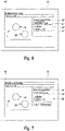
- a second schematic representation of a display view is shown, in which the user selects the plurality of setting parameters 42 for a second cylinder 45, which differs from the cylinder 41, and thereby defines different parameter values 44 for each selected setting parameter, since the second cylinder 45 in Compared to the cylinder 41 has a larger dimension (d2, h2). Also in 4 For example, clicking or double-clicking on the second cylinder 45 serves as an input command for the measurement command 40.
- the plurality of setting parameters 42 selected for the measurement command 40 is in turn received by the evaluation and control unit 34 and preferably stored.
- step S100 a large number of setting parameters, in this case at least partially different in terms of their parameter values, were received with regard to cylinders 41, 45 (step S100), which are used for steps S200 (evaluate) and S300 (determine) on the method side be used.
- the large number of setting parameters 42 is now evaluated statistically and/or by machine-aided learning in order to determine at least one setting parameter 48 as a default setting 46 from the evaluated large number of setting parameters 42 and to output this to the user as a setting parameter suggestion 50 when the same measurement command 40 is selected again (step S400).
- the evaluation according to the invention leads, for example, to metadata about the individual setting parameters 42 (e.g. for which measurement object dimension d1, h1, d2, h2 which setting parameter values were selected by the user) also being included.
- figure 5 is the output of a setting parameter suggestion 50 based on the number of setting parameters 42 (e.g. from Figures 3 and 4 ) determined preset is shown.
- the setting parameter suggestion 50 (e.g. acoustic, visual and/or tactile) is output by the method according to the invention .
- the user can accept this suggestion, for example, by pressing an OK button or reject it by pressing a Cancel button.
- the user measures a reflected light circle 54 on the measurement object 14 several times in a "Reflected light circle” submenu.
- a reflected light circle corresponds to a measuring element circle that is on the measured object 14 and with a so-called reflected light illumination (or also bright field illumination).
- -Field is measured, with the incident light illumination improving the detectability of the measurement object 14, in particular for optical measurement devices 100.
- the user preferably defines specific edge-finding parameters for each measured incident light circle.
- the user can also include other edge finding parameters, such as the light focus, e.g. by opening or closing a shutter in the software, which is done in the software by defining the reflected light circles 54 on the measurement object 14.
- edge finding parameters such as the light focus, e.g. by opening or closing a shutter in the software, which is done in the software by defining the reflected light circles 54 on the measurement object 14.
- the measurement of such a reflected light circuit 54 will be understood as a control command 40' in the sense of the invention.
- the user can select a large number of setting parameters 42' (for example illuminance, light color, etc.) for the reflected light circuit 54 and assign specific parameter values 44' to them.
- setting parameters 42' are received and evaluated for each measured reflected light circuit 54 in order to determine a preferred presetting 46' with regard to a specific control command from the evaluated setting parameters 42'.
- the method according to the invention was shown in a greatly simplified manner for better comprehensibility and representability.
- the input or control command cannot be, for example, by (actively) selecting the "Reflected light circle” button.
- the method and the device it is also possible for the method and the device to already recognize the measurement of (any) circle by the user as a control command.
- the system in particular through machine-aided learning, then recognizes, for example based on the context, that the user wants to measure a "circle of reflected light” and automatically sets the edge-finding parameters for "circle of reflected light" previously set by the user, which the user uses as the setting parameter suggestion 50' are displayed.
- the method according to the invention thus makes it possible to use the context to infer what the user could intend to do in the next step, at least with a certain probability, in order to output a suitable setting parameter suggestion to the user.
- the system or the method can recognize that the user the visibility of the user interface is not required. The system can then automatically hide the user interface as a setting parameter suggestion. The same also applies to repeated display of a user interface.
- all context-sensitive settings or actions that the user makes can be recognized as measurement or control commands or as a large number of setting parameters and evaluated according to the invention.
Landscapes
- Physics & Mathematics (AREA)
- General Physics & Mathematics (AREA)
- Health & Medical Sciences (AREA)
- General Health & Medical Sciences (AREA)
- Nuclear Medicine, Radiotherapy & Molecular Imaging (AREA)
- Radiology & Medical Imaging (AREA)
- Length Measuring Devices With Unspecified Measuring Means (AREA)
Claims (14)
- Procédé d'assistance d'un utilisateur lors de la création d'un plan de mesure pour une mesure à réaliser avec un appareil de mesure (100) dimensionnel et/ou lors de la commande de la mesure à réaliser avec l'appareil de mesure (100), le procédé comprenant les étapes suivantes :- fourniture d'un dispositif (10) destiné à commander l'appareil de mesure dimensionnel et à assister un utilisateur lors de la création d'un plan de mesure pour une mesure à réaliser avec l'appareil de mesure (100) dimensionnel et/ou pendant la mesure lors de la commande de la mesure à réaliser avec l'appareil de mesure (100), les étapes supplémentaires suivantes étant à exécuter par ce dispositif :- réception (S100) d'une pluralité de paramètres de réglage (42), qui sont sélectionnés par un utilisateur concernant une instruction de mesure ou de commande (40) parmi une pluralité d'instructions de mesure ou de commande pour la mesure à réaliser avec l'appareil de mesure (100) ;- interprétation (S200) de la pluralité de paramètres de réglage (42) sur la base d'une interprétation statistique et/ou d'une interprétation au moyen d'un apprentissage automatique ;- détermination (S300) d'un préréglage (46), par lequel au moins un paramètre de réglage (48) de la pluralité sélectionnée de paramètres de réglage (42) est affecté à l'instruction de mesure ou de commande (40) ; et- délivrance en sortie (S400) d'une proposition de paramètre de réglage (50) en se basant sur le préréglage (46) déterminé lorsqu'une instruction de saisie destinée à la sélection de l'instruction de mesure ou de commande (40) est reçue.
- Procédé selon la revendication 1, la pluralité de paramètres de réglage (42) comprenant respectivement des valeurs de paramètre (44) et/ou des informations concernant l'instruction de mesure ou de commande (40).
- Procédé selon la revendication 1 ou 2, une distribution de fréquence étant déterminée lors de l'interprétation statistique, dans laquelle une valeur de fréquence est attribuée à chacun de la pluralité reçue de paramètres de réglage (42).
- Procédé selon la revendication 3, l'au moins un paramètre de réglage (48) de la pluralité de paramètres de réglage (42) étant, lors de la détermination du préréglage, affecté à l'instruction de mesure ou de commande (40) en fonction de la distribution de fréquence.
- Procédé selon l'une des revendications 1 à 4, une distribution de probabilité étant déterminée lors de l'interprétation au moyen de l'apprentissage automatique, dans laquelle une valeur de probabilité est attribuée à chacun de la pluralité reçue de paramètres de réglage (42) .
- Procédé selon la revendication 5, l'au moins un paramètre de réglage (48) de la pluralité de paramètres de réglage (42) étant, lors de la détermination du préréglage (46), affecté à l'instruction de mesure ou de commande (40) en fonction de la distribution de probabilité.
- Procédé selon la revendication 5 ou 6, les valeurs de probabilité étant déterminées sur la base d'un jeu de données d'entraînement prédéterminé.
- Procédé selon l'une des revendications 1 à 7, les étapes de réception, d'interprétation, de détermination et de délivrance en sortie étant exécutées continuellement de manière répétitive.
- Procédé selon l'une des revendications 1 à 7, les étapes de réception, d'interprétation, de détermination et de délivrance en sortie étant exécutées uniquement lorsque l'utilisateur active un mode d'assistance prédéfini.
- Procédé selon l'une des revendications 1 à 9, le procédé comprenant en outre les étapes suivantes :- réception d'une instruction de saisie supplémentaire pour la sélection d'une instruction de mesure ou de commande jusque-là inconnue, qui est sélectionnée pour la première fois ;- comparaison de l'instruction de mesure ou de commande jusque-là inconnue à la pluralité d'instructions de mesure ou de commande ;- détermination d'une instruction de mesure ou de commande similaire parmi la pluralité d'instructions de mesure ou de commande, qui est similaire à l'instruction de mesure ou de commande jusque-là inconnue, sur la base de la comparaison ; et- délivrance en sortie d'une proposition de paramètre de réglage (50) pour l'instruction de mesure ou de commande similaire.
- Procédé selon l'une des revendications 1 à 9, le procédé comprenant en outre les étapes suivantes :- réception d'une instruction de saisie supplémentaire pour la sélection d'une instruction de mesure ou de commande jusque-là inconnue, qui est sélectionnée pour la première fois ;- comparaison de l'instruction de mesure ou de commande jusque-là inconnue à la pluralité d'instructions de mesure ou de commande ;- détermination d'au moins deux instructions de mesure ou de commande similaires parmi la pluralité d'instructions de mesure ou de commande, qui sont similaires à l'instruction de mesure ou de commande jusque-là inconnue, sur la base de la comparaison ;- interpolation entre les préréglages associés aux au moins deux instructions de mesure ou de commande similaires ; et- délivrance en sortie d'une proposition de paramètre de réglage interpolée.
- Produit de programme informatique comprenant un code de programme, qui est conçu pour que le dispositif selon l'une des revendications 13 et 14 mette en œuvre un procédé selon l'une des revendications 1 à 11.
- Dispositif de commande d'un appareil de mesure dimensionnel et d'assistance d'un utilisateur lors de la création d'un plan de mesure pour une mesure à réaliser avec l'appareil de mesure (100) dimensionnel et/ou d'assistance d'un utilisateur pendant la mesure lors de la commande de la mesure à réaliser avec l'appareil de mesure (100) dimensionnel, le dispositif (200) possédant un afficheur (38) et une unité d'interprétation et de commande (34), l'unité d'interprétation et de commande (34) étant reliée à l'afficheur (38) par le biais d'une liaison de données et étant conçu pour :- recevoir une pluralité de paramètres de réglage (42), qui sont sélectionnés par un utilisateur concernant une instruction de mesure ou de commande (40) parmi une pluralité d'instructions de mesure ou de commande pour la mesure à réaliser avec l'appareil de mesure (100) ;- interpréter la pluralité de paramètres de réglage (42) sur la base d'une interprétation statistique et/ou d'une interprétation au moyen d'un apprentissage automatique ;- déterminer un préréglage (46), par lequel au moins un paramètre de réglage (48) de la pluralité sélectionnée de paramètres de réglage (42) est affecté à l'instruction de mesure ou de commande (40) ; et- délivrer en sortie une proposition de paramètre de réglage (50) en se basant sur le préréglage (46) déterminé lorsqu'une instruction de saisie destinée à la sélection de l'instruction de mesure ou de commande (40) est reçue.
- Dispositif selon la revendication 13, le dispositif (200) conjointement avec des composants matériels et/ou logiciels supplémentaires étant compris dans un appareil de mesure (100), disposé sur celui-ci ou intégré dans celui-ci.
Priority Applications (2)
| Application Number | Priority Date | Filing Date | Title |
|---|---|---|---|
| EP20161279.3A EP3875899B1 (fr) | 2020-03-05 | 2020-03-05 | Procédé, produit-programme d'ordinateur et dispositif d'aide à un utilisateur à la création d'un plan de mesure et/ou à la commande d'une mesure à effectuer |
| US17/193,069 US11719534B2 (en) | 2020-03-05 | 2021-03-05 | Computerized creation of measurement plans and plan-based control of measurement devices |
Applications Claiming Priority (1)
| Application Number | Priority Date | Filing Date | Title |
|---|---|---|---|
| EP20161279.3A EP3875899B1 (fr) | 2020-03-05 | 2020-03-05 | Procédé, produit-programme d'ordinateur et dispositif d'aide à un utilisateur à la création d'un plan de mesure et/ou à la commande d'une mesure à effectuer |
Publications (2)
| Publication Number | Publication Date |
|---|---|
| EP3875899A1 EP3875899A1 (fr) | 2021-09-08 |
| EP3875899B1 true EP3875899B1 (fr) | 2022-05-04 |
Family
ID=69779880
Family Applications (1)
| Application Number | Title | Priority Date | Filing Date |
|---|---|---|---|
| EP20161279.3A Active EP3875899B1 (fr) | 2020-03-05 | 2020-03-05 | Procédé, produit-programme d'ordinateur et dispositif d'aide à un utilisateur à la création d'un plan de mesure et/ou à la commande d'une mesure à effectuer |
Country Status (2)
| Country | Link |
|---|---|
| US (1) | US11719534B2 (fr) |
| EP (1) | EP3875899B1 (fr) |
Family Cites Families (10)
| Publication number | Priority date | Publication date | Assignee | Title |
|---|---|---|---|---|
| US20010049589A1 (en) * | 1993-01-21 | 2001-12-06 | Nikon Corporation | Alignment method and apparatus therefor |
| FR2860900A1 (fr) * | 2003-10-08 | 2005-04-15 | Gerard Uzan | Procede & systeme d'interface homme-machine a choix contextualises de taches et de configurations par auxiliaire proposant |
| US7796278B2 (en) * | 2008-09-19 | 2010-09-14 | Gii Acquisition, Llc | Method for precisely measuring position of a part to be inspected at a part inspection station |
| DE102008049567A1 (de) * | 2008-09-30 | 2010-04-01 | Siemens Aktiengesellschaft | Verfahren zur Bilddatenaufnahme mit einer radiologischen Bildaufnahmeeinrichtung |
| DE102009049534A1 (de) * | 2009-10-06 | 2011-04-07 | Carl Zeiss Industrielle Messtechnik Gmbh | Koordinatenmessgerät mit Lageänderungssensoren |
| EP2881704B1 (fr) * | 2013-12-04 | 2018-05-09 | Hexagon Technology Center GmbH | Appareils et procédés de mesure automatisée d'un objet et produit de programme d'ordinateur correspondant |
| DE102014220313A1 (de) * | 2014-10-07 | 2016-04-07 | Carl Zeiss Industrielle Messtechnik Gmbh | Erfassung von geometrischen Abweichungen einer Bewegungsführung bei einemKoordinatenmessgerät oder einer Werkzeugmaschine |
| JP6425586B2 (ja) * | 2015-03-04 | 2018-11-21 | 株式会社キーエンス | 光学式変位計測システム、撮像条件最適化方法および撮像条件最適化プログラム |
| DE102018209570A1 (de) * | 2017-06-14 | 2018-12-20 | Carl Zeiss Industrielle Messtechnik Gmbh | Verfahren und Vorrichtung zur Erzeugung eines dreidimensionalen Abbilds |
| WO2019099547A2 (fr) * | 2017-11-14 | 2019-05-23 | Digital Alloys Incorporated | Procédés et systèmes de tranchage interactif permettant de générer des trajectoires d'outil pour l'impression d'objets tridimensionnels |
-
2020
- 2020-03-05 EP EP20161279.3A patent/EP3875899B1/fr active Active
-
2021
- 2021-03-05 US US17/193,069 patent/US11719534B2/en active Active
Also Published As
| Publication number | Publication date |
|---|---|
| EP3875899A1 (fr) | 2021-09-08 |
| US20210278206A1 (en) | 2021-09-09 |
| US11719534B2 (en) | 2023-08-08 |
Similar Documents
| Publication | Publication Date | Title |
|---|---|---|
| EP3286524B1 (fr) | Procédé et dispositif permettant de déterminer les propriétés dimensionnelles effectives d'un objet à mesurer | |
| DE102012220882B4 (de) | System und Verfahren unter Verwendung eines Bearbeitungsinitialisierungsblocks in einer Teileprogramm-Bearbeitungsumgebung in einem Maschinenvisionssystem | |
| DE102012220884A1 (de) | Maschinensichtsystemprogramm-Bearbeitungsumgebung mit Echtzeitkontexterzeugungsmerkmalen | |
| DE102012216908B4 (de) | Verfahren unter Verwendung einer Bildkorrelation zum Bestimmen von Positionsmessungen in einem Maschinenvisionssystem | |
| DE10122699A1 (de) | Verfahren und Vorrichtung zum Erzeugen von Teileprogrammen zur Verwendung in Bildmessinstrumenten, und Bildmessinstrument und Verfahren zur Darstellung damit gemessener Ergebnisse | |
| EP3274654B1 (fr) | Procédé, dispositif et produit programme d'ordinateur de détermination de propriétés en matière de dimension d'un objet mesuré | |
| DE102012220759A1 (de) | Programmbearbeitungsumgebung eines maschinell sehenden Systems mit synchronisierten Benutzerschnittstellenmerkmalen | |
| EP3403051B1 (fr) | Procédé et dispositif pour définir des données de consigne pour un mesurage d'une pièce à mesurer au moyen d'un appareil de mesure de coordonnées et/ou pour évaluer des résultats de mesure d'un mesurage d'une pièce mesurée au moyen d'un appareil de mesure de coordonnées | |
| EP4056945A1 (fr) | Validation des protocoles d'essai destinée à la mesure d'objet à l'aide d'un appareil de mesure de coordonnées | |
| EP2115538B1 (fr) | Commande d'un fonctionnement d'un appareil de mesure de coordonnées | |
| WO2002023292A9 (fr) | Procede pour generer un programme de mesure destine a un appareil de mesure de coordonnees | |
| EP3901563B1 (fr) | Procédé et dispositif de détermination d'une stratégie de mesure permettant de mesurer un objet de mesure et programme | |
| EP3875899B1 (fr) | Procédé, produit-programme d'ordinateur et dispositif d'aide à un utilisateur à la création d'un plan de mesure et/ou à la commande d'une mesure à effectuer | |
| EP3835900B1 (fr) | Procédé et dispositif d'essai de pièces | |
| WO1999058931A1 (fr) | Commande d'un appareil de mesure de coordonnees avec une caracteristique de verification et un element geometrique subsequent | |
| EP3865979A1 (fr) | Procédé et dispositif d'aide à une planification basée sur un logiciel d'une mesure dimensionnelle | |
| DE102017203530B4 (de) | Vorrichtung zum Generieren eines Teileprogramms eines Geräts zum Messen einer Oberflächenbeschaffenheit | |
| EP1377884B1 (fr) | Appareil de mesure de coordonnees | |
| DE10209141A1 (de) | Verfahren zur Kalibrierung von parallelkinematisch in einem Bewegungsraum bewegten Maschineneinheiten in Werkzeugmaschinen und Handhabungsgeräten | |
| EP3889890A1 (fr) | Procédé de détection d'objet de mesure à base de données d'image | |
| DE112022000384T5 (de) | Lehrvorrichtung und lehrverfahren zum lehren der bedienung einer laserbearbeitungsvorrichtung | |
| DE102020211699A1 (de) | Verfahren, Mikroskop und Computerprogramm zum Bestimmen einer Manipulationsposition im probennahen Bereich | |
| WO1994007187A1 (fr) | Procede permettant de verifier la precision d'une machine a commande numerique | |
| EP3696496B1 (fr) | Vérification des réglages de paramètres de mesure pour le fonctionnement d'un appareil de mesure de coordonnées | |
| DE102019128103A1 (de) | Kalibrierung eines aktiven optischen Sensorsystems |
Legal Events
| Date | Code | Title | Description |
|---|---|---|---|
| PUAI | Public reference made under article 153(3) epc to a published international application that has entered the european phase |
Free format text: ORIGINAL CODE: 0009012 |
|
| STAA | Information on the status of an ep patent application or granted ep patent |
Free format text: STATUS: REQUEST FOR EXAMINATION WAS MADE |
|
| 17P | Request for examination filed |
Effective date: 20210224 |
|
| AK | Designated contracting states |
Kind code of ref document: A1 Designated state(s): AL AT BE BG CH CY CZ DE DK EE ES FI FR GB GR HR HU IE IS IT LI LT LU LV MC MK MT NL NO PL PT RO RS SE SI SK SM TR |
|
| GRAP | Despatch of communication of intention to grant a patent |
Free format text: ORIGINAL CODE: EPIDOSNIGR1 |
|
| STAA | Information on the status of an ep patent application or granted ep patent |
Free format text: STATUS: GRANT OF PATENT IS INTENDED |
|
| RIC1 | Information provided on ipc code assigned before grant |
Ipc: G01B 21/04 20060101AFI20211104BHEP |
|
| INTG | Intention to grant announced |
Effective date: 20211125 |
|
| GRAS | Grant fee paid |
Free format text: ORIGINAL CODE: EPIDOSNIGR3 |
|
| GRAA | (expected) grant |
Free format text: ORIGINAL CODE: 0009210 |
|
| STAA | Information on the status of an ep patent application or granted ep patent |
Free format text: STATUS: THE PATENT HAS BEEN GRANTED |
|
| AK | Designated contracting states |
Kind code of ref document: B1 Designated state(s): AL AT BE BG CH CY CZ DE DK EE ES FI FR GB GR HR HU IE IS IT LI LT LU LV MC MK MT NL NO PL PT RO RS SE SI SK SM TR |
|
| REG | Reference to a national code |
Ref country code: GB Ref legal event code: FG4D Free format text: NOT ENGLISH |
|
| RIN1 | Information on inventor provided before grant (corrected) |
Inventor name: HERSACHER, STEFFEN Inventor name: NEUMAIER, KILIAN Inventor name: RITTER, MARKUS |
|
| REG | Reference to a national code |
Ref country code: CH Ref legal event code: EP |
|
| REG | Reference to a national code |
Ref country code: AT Ref legal event code: REF Ref document number: 1489494 Country of ref document: AT Kind code of ref document: T Effective date: 20220515 |
|
| REG | Reference to a national code |
Ref country code: DE Ref legal event code: R096 Ref document number: 502020001029 Country of ref document: DE |
|
| REG | Reference to a national code |
Ref country code: IE Ref legal event code: FG4D Free format text: LANGUAGE OF EP DOCUMENT: GERMAN |
|
| REG | Reference to a national code |
Ref country code: LT Ref legal event code: MG9D |
|
| REG | Reference to a national code |
Ref country code: NL Ref legal event code: MP Effective date: 20220504 |
|
| PG25 | Lapsed in a contracting state [announced via postgrant information from national office to epo] |
Ref country code: SE Free format text: LAPSE BECAUSE OF FAILURE TO SUBMIT A TRANSLATION OF THE DESCRIPTION OR TO PAY THE FEE WITHIN THE PRESCRIBED TIME-LIMIT Effective date: 20220504 Ref country code: PT Free format text: LAPSE BECAUSE OF FAILURE TO SUBMIT A TRANSLATION OF THE DESCRIPTION OR TO PAY THE FEE WITHIN THE PRESCRIBED TIME-LIMIT Effective date: 20220905 Ref country code: NO Free format text: LAPSE BECAUSE OF FAILURE TO SUBMIT A TRANSLATION OF THE DESCRIPTION OR TO PAY THE FEE WITHIN THE PRESCRIBED TIME-LIMIT Effective date: 20220804 Ref country code: NL Free format text: LAPSE BECAUSE OF FAILURE TO SUBMIT A TRANSLATION OF THE DESCRIPTION OR TO PAY THE FEE WITHIN THE PRESCRIBED TIME-LIMIT Effective date: 20220504 Ref country code: LT Free format text: LAPSE BECAUSE OF FAILURE TO SUBMIT A TRANSLATION OF THE DESCRIPTION OR TO PAY THE FEE WITHIN THE PRESCRIBED TIME-LIMIT Effective date: 20220504 Ref country code: HR Free format text: LAPSE BECAUSE OF FAILURE TO SUBMIT A TRANSLATION OF THE DESCRIPTION OR TO PAY THE FEE WITHIN THE PRESCRIBED TIME-LIMIT Effective date: 20220504 Ref country code: GR Free format text: LAPSE BECAUSE OF FAILURE TO SUBMIT A TRANSLATION OF THE DESCRIPTION OR TO PAY THE FEE WITHIN THE PRESCRIBED TIME-LIMIT Effective date: 20220805 Ref country code: FI Free format text: LAPSE BECAUSE OF FAILURE TO SUBMIT A TRANSLATION OF THE DESCRIPTION OR TO PAY THE FEE WITHIN THE PRESCRIBED TIME-LIMIT Effective date: 20220504 Ref country code: BG Free format text: LAPSE BECAUSE OF FAILURE TO SUBMIT A TRANSLATION OF THE DESCRIPTION OR TO PAY THE FEE WITHIN THE PRESCRIBED TIME-LIMIT Effective date: 20220804 |
|
| PG25 | Lapsed in a contracting state [announced via postgrant information from national office to epo] |
Ref country code: RS Free format text: LAPSE BECAUSE OF FAILURE TO SUBMIT A TRANSLATION OF THE DESCRIPTION OR TO PAY THE FEE WITHIN THE PRESCRIBED TIME-LIMIT Effective date: 20220504 Ref country code: PL Free format text: LAPSE BECAUSE OF FAILURE TO SUBMIT A TRANSLATION OF THE DESCRIPTION OR TO PAY THE FEE WITHIN THE PRESCRIBED TIME-LIMIT Effective date: 20220504 Ref country code: LV Free format text: LAPSE BECAUSE OF FAILURE TO SUBMIT A TRANSLATION OF THE DESCRIPTION OR TO PAY THE FEE WITHIN THE PRESCRIBED TIME-LIMIT Effective date: 20220504 Ref country code: IS Free format text: LAPSE BECAUSE OF FAILURE TO SUBMIT A TRANSLATION OF THE DESCRIPTION OR TO PAY THE FEE WITHIN THE PRESCRIBED TIME-LIMIT Effective date: 20220904 |
|
| PG25 | Lapsed in a contracting state [announced via postgrant information from national office to epo] |
Ref country code: SM Free format text: LAPSE BECAUSE OF FAILURE TO SUBMIT A TRANSLATION OF THE DESCRIPTION OR TO PAY THE FEE WITHIN THE PRESCRIBED TIME-LIMIT Effective date: 20220504 Ref country code: SK Free format text: LAPSE BECAUSE OF FAILURE TO SUBMIT A TRANSLATION OF THE DESCRIPTION OR TO PAY THE FEE WITHIN THE PRESCRIBED TIME-LIMIT Effective date: 20220504 Ref country code: RO Free format text: LAPSE BECAUSE OF FAILURE TO SUBMIT A TRANSLATION OF THE DESCRIPTION OR TO PAY THE FEE WITHIN THE PRESCRIBED TIME-LIMIT Effective date: 20220504 Ref country code: ES Free format text: LAPSE BECAUSE OF FAILURE TO SUBMIT A TRANSLATION OF THE DESCRIPTION OR TO PAY THE FEE WITHIN THE PRESCRIBED TIME-LIMIT Effective date: 20220504 Ref country code: EE Free format text: LAPSE BECAUSE OF FAILURE TO SUBMIT A TRANSLATION OF THE DESCRIPTION OR TO PAY THE FEE WITHIN THE PRESCRIBED TIME-LIMIT Effective date: 20220504 Ref country code: DK Free format text: LAPSE BECAUSE OF FAILURE TO SUBMIT A TRANSLATION OF THE DESCRIPTION OR TO PAY THE FEE WITHIN THE PRESCRIBED TIME-LIMIT Effective date: 20220504 Ref country code: CZ Free format text: LAPSE BECAUSE OF FAILURE TO SUBMIT A TRANSLATION OF THE DESCRIPTION OR TO PAY THE FEE WITHIN THE PRESCRIBED TIME-LIMIT Effective date: 20220504 |
|
| REG | Reference to a national code |
Ref country code: DE Ref legal event code: R097 Ref document number: 502020001029 Country of ref document: DE |
|
| PLBE | No opposition filed within time limit |
Free format text: ORIGINAL CODE: 0009261 |
|
| STAA | Information on the status of an ep patent application or granted ep patent |
Free format text: STATUS: NO OPPOSITION FILED WITHIN TIME LIMIT |
|
| PG25 | Lapsed in a contracting state [announced via postgrant information from national office to epo] |
Ref country code: AL Free format text: LAPSE BECAUSE OF FAILURE TO SUBMIT A TRANSLATION OF THE DESCRIPTION OR TO PAY THE FEE WITHIN THE PRESCRIBED TIME-LIMIT Effective date: 20220504 |
|
| 26N | No opposition filed |
Effective date: 20230207 |
|
| P01 | Opt-out of the competence of the unified patent court (upc) registered |
Effective date: 20230525 |
|
| PG25 | Lapsed in a contracting state [announced via postgrant information from national office to epo] |
Ref country code: MC Free format text: LAPSE BECAUSE OF FAILURE TO SUBMIT A TRANSLATION OF THE DESCRIPTION OR TO PAY THE FEE WITHIN THE PRESCRIBED TIME-LIMIT Effective date: 20220504 |
|
| REG | Reference to a national code |
Ref country code: CH Ref legal event code: PL |
|
| REG | Reference to a national code |
Ref country code: BE Ref legal event code: MM Effective date: 20230331 |
|
| PG25 | Lapsed in a contracting state [announced via postgrant information from national office to epo] |
Ref country code: LU Free format text: LAPSE BECAUSE OF NON-PAYMENT OF DUE FEES Effective date: 20230305 |
|
| REG | Reference to a national code |
Ref country code: IE Ref legal event code: MM4A |
|
| PG25 | Lapsed in a contracting state [announced via postgrant information from national office to epo] |
Ref country code: LI Free format text: LAPSE BECAUSE OF NON-PAYMENT OF DUE FEES Effective date: 20230331 Ref country code: IT Free format text: LAPSE BECAUSE OF FAILURE TO SUBMIT A TRANSLATION OF THE DESCRIPTION OR TO PAY THE FEE WITHIN THE PRESCRIBED TIME-LIMIT Effective date: 20220504 Ref country code: IE Free format text: LAPSE BECAUSE OF NON-PAYMENT OF DUE FEES Effective date: 20230305 Ref country code: FR Free format text: LAPSE BECAUSE OF NON-PAYMENT OF DUE FEES Effective date: 20230331 Ref country code: CH Free format text: LAPSE BECAUSE OF NON-PAYMENT OF DUE FEES Effective date: 20230331 |
|
| PG25 | Lapsed in a contracting state [announced via postgrant information from national office to epo] |
Ref country code: BE Free format text: LAPSE BECAUSE OF NON-PAYMENT OF DUE FEES Effective date: 20230331 |
|
| PGFP | Annual fee paid to national office [announced via postgrant information from national office to epo] |
Ref country code: DE Payment date: 20240320 Year of fee payment: 5 |