EP3875862A1 - Wärmepumpe - Google Patents
Wärmepumpe Download PDFInfo
- Publication number
- EP3875862A1 EP3875862A1 EP20161643.0A EP20161643A EP3875862A1 EP 3875862 A1 EP3875862 A1 EP 3875862A1 EP 20161643 A EP20161643 A EP 20161643A EP 3875862 A1 EP3875862 A1 EP 3875862A1
- Authority
- EP
- European Patent Office
- Prior art keywords
- heat pump
- fan
- ventilation duct
- air
- installation room
- Prior art date
- Legal status (The legal status is an assumption and is not a legal conclusion. Google has not performed a legal analysis and makes no representation as to the accuracy of the status listed.)
- Pending
Links
Images





Classifications
-
- F—MECHANICAL ENGINEERING; LIGHTING; HEATING; WEAPONS; BLASTING
- F24—HEATING; RANGES; VENTILATING
- F24F—AIR-CONDITIONING; AIR-HUMIDIFICATION; VENTILATION; USE OF AIR CURRENTS FOR SCREENING
- F24F13/00—Details common to, or for air-conditioning, air-humidification, ventilation or use of air currents for screening
- F24F13/20—Casings or covers
-
- F—MECHANICAL ENGINEERING; LIGHTING; HEATING; WEAPONS; BLASTING
- F24—HEATING; RANGES; VENTILATING
- F24F—AIR-CONDITIONING; AIR-HUMIDIFICATION; VENTILATION; USE OF AIR CURRENTS FOR SCREENING
- F24F11/00—Control or safety arrangements
- F24F11/30—Control or safety arrangements for purposes related to the operation of the system, e.g. for safety or monitoring
- F24F11/32—Responding to malfunctions or emergencies
- F24F11/36—Responding to malfunctions or emergencies to leakage of heat-exchange fluid
-
- F—MECHANICAL ENGINEERING; LIGHTING; HEATING; WEAPONS; BLASTING
- F24—HEATING; RANGES; VENTILATING
- F24H—FLUID HEATERS, e.g. WATER OR AIR HEATERS, HAVING HEAT-GENERATING MEANS, e.g. HEAT PUMPS, IN GENERAL
- F24H15/00—Control of fluid heaters
- F24H15/10—Control of fluid heaters characterised by the purpose of the control
- F24H15/12—Preventing or detecting fluid leakage
-
- F—MECHANICAL ENGINEERING; LIGHTING; HEATING; WEAPONS; BLASTING
- F24—HEATING; RANGES; VENTILATING
- F24H—FLUID HEATERS, e.g. WATER OR AIR HEATERS, HAVING HEAT-GENERATING MEANS, e.g. HEAT PUMPS, IN GENERAL
- F24H15/00—Control of fluid heaters
- F24H15/30—Control of fluid heaters characterised by control outputs; characterised by the components to be controlled
- F24H15/345—Control of fans, e.g. on-off control
- F24H15/35—Control of the speed of fans
-
- F—MECHANICAL ENGINEERING; LIGHTING; HEATING; WEAPONS; BLASTING
- F24—HEATING; RANGES; VENTILATING
- F24H—FLUID HEATERS, e.g. WATER OR AIR HEATERS, HAVING HEAT-GENERATING MEANS, e.g. HEAT PUMPS, IN GENERAL
- F24H15/00—Control of fluid heaters
- F24H15/30—Control of fluid heaters characterised by control outputs; characterised by the components to be controlled
- F24H15/375—Control of heat pumps
-
- F—MECHANICAL ENGINEERING; LIGHTING; HEATING; WEAPONS; BLASTING
- F24—HEATING; RANGES; VENTILATING
- F24H—FLUID HEATERS, e.g. WATER OR AIR HEATERS, HAVING HEAT-GENERATING MEANS, e.g. HEAT PUMPS, IN GENERAL
- F24H9/00—Details
- F24H9/20—Arrangement or mounting of control or safety devices
-
- F—MECHANICAL ENGINEERING; LIGHTING; HEATING; WEAPONS; BLASTING
- F24—HEATING; RANGES; VENTILATING
- F24F—AIR-CONDITIONING; AIR-HUMIDIFICATION; VENTILATION; USE OF AIR CURRENTS FOR SCREENING
- F24F13/00—Details common to, or for air-conditioning, air-humidification, ventilation or use of air currents for screening
- F24F13/24—Means for preventing or suppressing noise
- F24F2013/242—Sound-absorbing material
-
- F—MECHANICAL ENGINEERING; LIGHTING; HEATING; WEAPONS; BLASTING
- F24—HEATING; RANGES; VENTILATING
- F24H—FLUID HEATERS, e.g. WATER OR AIR HEATERS, HAVING HEAT-GENERATING MEANS, e.g. HEAT PUMPS, IN GENERAL
- F24H4/00—Fluid heaters characterised by the use of heat pumps
-
- F—MECHANICAL ENGINEERING; LIGHTING; HEATING; WEAPONS; BLASTING
- F25—REFRIGERATION OR COOLING; COMBINED HEATING AND REFRIGERATION SYSTEMS; HEAT PUMP SYSTEMS; MANUFACTURE OR STORAGE OF ICE; LIQUEFACTION SOLIDIFICATION OF GASES
- F25B—REFRIGERATION MACHINES, PLANTS OR SYSTEMS; COMBINED HEATING AND REFRIGERATION SYSTEMS; HEAT PUMP SYSTEMS
- F25B2400/00—Component parts or details not otherwise provided for in this subclass
- F25B2400/12—Inflammable refrigerants
-
- F—MECHANICAL ENGINEERING; LIGHTING; HEATING; WEAPONS; BLASTING
- F25—REFRIGERATION OR COOLING; COMBINED HEATING AND REFRIGERATION SYSTEMS; HEAT PUMP SYSTEMS; MANUFACTURE OR STORAGE OF ICE; LIQUEFACTION SOLIDIFICATION OF GASES
- F25B—REFRIGERATION MACHINES, PLANTS OR SYSTEMS; COMBINED HEATING AND REFRIGERATION SYSTEMS; HEAT PUMP SYSTEMS
- F25B2500/00—Problems to be solved
- F25B2500/22—Preventing, detecting or repairing leaks of refrigeration fluids
- F25B2500/222—Detecting refrigerant leaks
-
- F—MECHANICAL ENGINEERING; LIGHTING; HEATING; WEAPONS; BLASTING
- F25—REFRIGERATION OR COOLING; COMBINED HEATING AND REFRIGERATION SYSTEMS; HEAT PUMP SYSTEMS; MANUFACTURE OR STORAGE OF ICE; LIQUEFACTION SOLIDIFICATION OF GASES
- F25B—REFRIGERATION MACHINES, PLANTS OR SYSTEMS; COMBINED HEATING AND REFRIGERATION SYSTEMS; HEAT PUMP SYSTEMS
- F25B49/00—Arrangement or mounting of control or safety devices
- F25B49/005—Arrangement or mounting of control or safety devices of safety devices
Definitions
- the present invention relates to a heat pump, in particular a heat pump which is designed for installation in an installation room.
- climate-friendly refrigerants In the recent past, the search for climate-friendly refrigerants has increased. However, the disadvantage of many climate-friendly refrigerants is their flammability. The use of such refrigerants, for example in heat pumps, therefore leads to special safety requirements. In order to ensure that there is no unwanted ignition of any refrigerant escaping from a refrigeration circuit, a minimum volume or a minimum space is prescribed in which the escaping refrigerant is distributed in order to achieve sufficient mixing.
- flammable refrigerants are mainly used in heat pumps installed outdoors, or the amount of refrigerant is reduced so much that a leak cannot cause any significant damage.
- the standard specifies the three named variants according to which the refrigerant is allowed to escape. Different heat pumps can therefore only be used for certain installation locations, more precisely the sizes of installation rooms.
- a heat pump in particular a heat pump for installation in an installation room, is proposed with a housing, a refrigeration circuit arranged in a machine room with a combustible refrigerant, in particular R454C, and a ventilation duct for discharging escaping refrigerant.
- a fan is assigned to the ventilation duct, the ventilation duct being connected to an air line which is suitable for guiding the installation room air out of the installation room.
- the air line points into a mixing portal, the mixing portal being connected to the ventilation duct and the machine room and being suitable for bringing the installation room air and machine room air together.
- a heat pump in particular a heat pump for installation in an installation room, with a housing, a cooling circuit arranged in a machine room with a flammable refrigerant, in particular R454C, and a ventilation duct for discharging escaping refrigerant is also proposed.
- the heat pump has a fan which is connected to the ventilation duct. A pressure side of the fan is assigned to an end section. One suction side of the fan is assigned to the machine room and the suction side has an air connection to the installation room.
- the fan is advantageously arranged in the ventilation duct.
- One suction side is directed towards an outlet opening which represents an opening in the housing and as a result of which, in the event of a fault, refrigerant escaping from the refrigerant circuit is sucked to the fan.
- the refrigerant is then conducted by the fan through the ventilation duct to an end section and blown from the heat pump or from the machine room into the installation room.
- the suction side of the fan is advantageously also connected to the installation room by means of an air line.
- the ventilation duct advantageously has an inlet opening, as a result of which the installation room air can flow to the fan. Since the fan is designed for permanent operation, and also permanently, i.e.
- the installation room air is continuously drawn in via the suction side of the fan. Accordingly, there is a permanent and permanent volume flow of installation room air through the inlet opening, through the air connection to the suction side of the fan. There, the installation room air is conveyed through the air duct to the end section. Only in the event of a leak, when refrigerant escapes from the refrigerant circuit, is this refrigerant conveyed through an outlet opening in the machine room to the suction side of the fan.
- the outside air and the refrigerant are advantageously brought together in a mixing portal, which is located in front of the suction side of the fan. At least a first mixing of outside air and refrigerant advantageously takes place here. In the event of a leak, refrigerant and outside air flow further in the air duct and continue to mix to form a mixed volume flow.
- the suction side of the fan is only connected to the installation room and permanently draws in installation room air directly.
- a connection between the outlet opening and the fan is advantageously not provided.
- the outside air then flows in the ventilation duct to a Venturi nozzle.
- the Venturi nozzle has an air connection, which advantageously has an acceleration unit.
- the Venturi nozzle is advantageously connected to the machine room via the outlet opening and through the Negative pressure in the venturi creates a negative pressure in the engine room. In the event of a leak, the negative pressure in the Venturi nozzle sucks refrigerant out of the machine room through the outlet opening.
- the mixing portal is the area where the outside air meets the refrigerant. Outside air, which is brought together with refrigerant, thus flows through the air connection, which is advantageously carried out in the Venturi nozzle in the mixing portal. Furthermore, in the event of a leak, a mixed volume flows out of the Venturi nozzle and continues in the ventilation duct to the end section.
- the mixing portal is a zone where outside air and, in the event of a leak, refrigerant meet.
- the mixing portal is advantageously formed by the end of the air line and the suction side of the fan. According to another concept of the invention, the mixing portal is formed in the Venturi nozzle, or after the Venturi nozzle, by the air line of the Venturi nozzle and the outlet opening.
- refrigerant and installation room air are advantageously mixed. After leaving the ventilation duct, advantageously through a perforated plate, the refrigerant is further mixed with the outside air.
- a negative pressure is generated in a machine room of the housing of the heat pump with an outside air flow, the fan running permanently and installation room air being sucked in permanently from the installation room.
- refrigerant in a refrigerant circuit is sucked out of the machine room and mixed with the installation room air from the installation room.
- the coolant is advantageously sucked in at least indirectly by the fan from the machine room and the mixture of coolant from the machine room and installation room air is conveyed back into the installation room.
- a refrigerant-air mixture is continuously conveyed through the ventilation duct from the installation room by the fan, even if the refrigerant has already been conveyed from the machine room to the installation room, with the air and refrigerant being conveyed continuously in the event of a leak.
- This means that the air and / or the refrigerant in the installation room is permanently moved and mixed with the air in the installation room there.
- the permanent running of the fan advantageously includes possible calibration cycles in which it runs slowly.
- a fan that clocks in an on-off mode also advantageously falls under the term permanent operation, even if the fan comes to a standstill for a short time, in particular for a calibration or safety mode.
- a fan that varies in speed also falls under "permanent operation”. It is also advantageous to set the speed of the fan or its delivery capacity depending on a leakage detection. If a leak is detected, the speed or the delivery volume flow of the fan is advantageously increased.
- Leak detection is advantageously provided, with which an error signal is displayed and advantageously sent by e-mail and the heat pump is switched off, advantageously switched to a voltage-free state, the fan continuing to run, advantageously with mains and / or battery operation.
- a heat pump as standard in accordance with variant 1 described above, that is, to allow the refrigerant to flow out independently in an end section located at one end of the ventilation duct.
- the ventilation duct can be designed as a rectangular duct attached to the outside of the heat pump.
- a ventilation duct integrated into a side wall, rear wall or front wall is advantageous.
- the ventilation duct is integrated into a side wall, front wall or rear wall of the heat pump, where thermal insulation or sound insulation is advantageously also provided.
- a ventilation channel with a labyrinth is advantageously provided in front of and or behind the fan, in particular an inlet labyrinth in front of the fan and in particular an outlet labyrinth after the fan.
- the suction side of the fan is connected to the machine room via the outlet opening and to the installation room via the inlet opening.
- the pressure side of the fan is connected to the outlet labyrinth.
- the mixing portal is advantageously formed behind the outlet labyrinth, advantageously primarily in front of the suction side of the fan.
- the mixing portal is advantageously a zone where the outside air and the refrigerant that may escape in the event of a leak meet. It there is also advantageously a first mixture of outside air and refrigerant. A volume flow of refrigerant and outside air is then sucked through the suction side into the fan and further mixed there and advantageously in the downstream outlet labyrinth and flows as a mixed volume flow to the end section, where a perforated plate is advantageously provided through which the mixed volume flow into the installation room flows.
- the inlet opening is advantageously arranged close to the floor in order to suck off the flammable refrigerant, which is usually of a higher density, from the floor area of the installation room and to convey it through the ventilation duct into a higher zone of the installation room.
- the vent channel has the end section with a planned height of at least about 80 cm or a value of more than 80 cm above the ground.
- the exit height of the mixed volume flow or the exit height of the refrigerant from the end section can be increased by means of an attachable air duct. If necessary, air ducts that are plugged or applied to the ventilation duct have a length of at least 30 cm and more in order to bring the end section into a higher position in the installation room, advantageously about 1.50 m or more.
- the ventilation duct is formed by a pipe, in particular a flexible pipe, laid in the machine room of the heat pump or generally in the heat pump or on the heat pump, or a hose.
- the mixing portal can be formed by a Venturi nozzle, which is advantageously arranged in the pipe or hose and has a connection to the installation room air and to the machine room.
- the ventilation duct is designed as a hose and is furthermore advantageously connected to the fan.
- the housing advantageously has an outlet opening and the ventilation channel adjoins the outlet opening.
- the ventilation channel has a closable receptacle which is designed to accommodate a fan.
- a closable receptacle for the fan is provided in the ventilation channel, which adjoins the outlet opening of the housing and is therefore accessible from the outside.
- the closable receptacle enables the venting channel to leak only at one end opposite the outlet opening, but not in the area of the receptacle, and the outflow of refrigerant does not occur in the area of the receptacle.
- the housing is preferably tight.
- tight means in particular that the sum of the openings is less than 5 cm 2 or advantageously significantly less than 2 cm 2 .
- the height of the end of the ventilation duct can be used to calculate the minimum size of the installation room, since neither the ventilation duct nor the housing have openings at a lower location that are greater than 5 cm 2 in total.
- the ventilation channel is preferably designed as a flat channel, in particular as a flat channel in a rectangular shape.
- a flat duct has the advantage that a particularly large cross-sectional area can be achieved without the ventilation duct protruding far beyond the housing of the heat pump.
- a flat duct can rest particularly well on the housing of the heat pump and therefore not excessively increase the dimensions of the heat pump.
- the ventilation duct preferably has coupling means for connecting an external air duct.
- the ventilation duct is particularly preferably an air duct made in standard dimensions, so that coupling with other available air duct elements is possible.
- the external air duct enables the heat pump to be expanded to include variant 3 of the above-mentioned safety concept.
- the ventilation duct can be extended to the outside of the installation room and a discharge from any escaping refrigerant from the installation room can be reached. This reduces the minimum size of the installation room in this variant to 0 m 2 .
- the ventilation duct preferably has sound insulation in its interior.
- the opening in the tight and sound-insulated housing of the heat pump which is created by the outlet opening, ensures that noises from the inside of the heat pump can escape through the ventilation duct.
- the ventilation duct preferably acts as a splitter silencer and can accordingly reduce the noises that can be measured outside the heat pump.
- the outlet opening is arranged on an underside of the housing and the ventilation channel runs from the outlet opening below the housing to a rear side of the housing and upwards behind the rear side.
- This advantageous guidance of the ventilation channel ensures that one end of the ventilation channel is high up, for example in the area of the upper edge of the housing or even above it. This means that the minimum size of the installation room can be reduced even without the fan being provided.
- the shape which accordingly deflects the air flow twice, once from vertically in the direction of the outlet opening to horizontally under the housing, and then to vertically upwards in the area of the rear edge, enables any sound that is generated to be shielded particularly well by the double deflection .
- the closable receptacle is preferably arranged in such a way that it is accessible from a front side of the housing of the heat pump.
- the closable receptacle can, for example, directly adjoin the ventilation opening and adjoin a bottom surface of the housing.
- the lockable receptacle can then be accessible below the housing, which stands for example on feet, and a fan to be installed can be inserted into the receptacle from the front if necessary. Maintenance and servicing of the fan is also easily possible, since the mount for maintaining the fan is also accessible from the front of the heat pump.
- the heat pump preferably also has a fan, in particular a radial fan, which is received in the receptacle of the ventilation duct.
- the heat pump is preferably designed as an internally installed brine-to-water heat pump or a water-to-water heat pump.
- a relevant difference compared to air-water heat pumps is that brine heat pumps usually do not have any fans that can be used to convey any refrigerant that may escape from the installation room, so that additional elements must be provided to ensure the safety requirements .
- a method for configuring an internally installed heat pump according to the invention having, depending on the size of an installation room: lengthening a ventilation duct of the heat pump to a greater height in the installation room; Providing a fan, in particular a radial fan in a receptacle of the ventilation duct, and / or lengthening the ventilation duct out of the installation room.
- the fan is advantageously operated with a power of approx. 2 W or less. But higher outputs are also advantageous, depending in particular on the counter pressure in the ventilation duct.
- the fan advantageously has a rated power of around 0.5 W to 20 W.
- An advantageous delivery volume is between 10 m3 / h and 100 m3 / h. A delivery volume of approx. 300 m 3 can be advantageous, especially in the event of a leak.
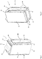
- FIGS 1 and 2 show schematic and exemplary perspective views of a heat pump 1 according to the invention from different directions.
- the heat pump 1 has a housing 10 with a front side 12, a side part 13, a rear side 14, an upper side 16 and a lower side 18.
- a cover 20 can usually be opened for maintenance and configuration of the heat pump 1 and enables access to the internal components.
- Connections 22 are usually also formed in the area of the top 16.
- a refrigeration circuit not shown, is arranged.
- a ventilation duct 30 is arranged below and behind the device.
- the ventilation channel 30 arises in a section 32 in which the housing 10 has an outlet opening (cf. Fig. 3-5 ), leads from there to the rear along the bottom 18 of the housing 10 and then vertically upwards, behind the rear side 14 of the housing 10.
- An opening is formed at an upper end portion 34 of the ventilation duct 30, which has coupling means for connecting a external air duct 50 are formed.
- the particularly preferred dimensioning of the ventilation duct 30 is shown as a rectangular flat duct. So that the weight of the entire heat pump 1 does not rest on the ventilation duct 30, the heat pump 1 also has feet 19 on its bottom 18.
- a closable receptacle 36 of the ventilation duct 30 is accessible from the front side 12.
- a fan can be mounted via the closable receptacle 36, as will be described later with reference to Figures 4 and 5 will be further described.
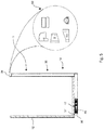
- Fig. 3 shows schematically and by way of example a cross section through the heat pump 1 according to the invention.
- the cover 20 which seals the housing 10 at the top.
- an outlet opening 17 can be seen which is provided in the bottom of the housing 10 and leads directly into the interior of the receptacle 36 of the ventilation duct.
- a sound insulation 38 is also arranged in the ventilation duct 30.
- the ventilation duct 30 thus also acts as a splitter silencer around the emerging outlet opening 17.
- an external air duct 50 can be connected to the upper end 34 of the ventilation duct 30.
- FIG Fig. 3 shown are preferably standard components and dimensions of ventilation ducts, so that the heat pump 1 according to the invention can advantageously be combined with existing solutions.
- Fig. 3 is indicated by arrows which path the exiting refrigerant takes up to the end 34 of the vent channel 30.
- the exit height can be increased further and thereby the minimum size of the installation room can be greatly reduced. This can happen in particular if the installation room would be too small without the extension by means of the external air duct 50.
- a fan 40 as shown schematically and by way of example in FIG Fig. 4 shown is supplementary received in the closable receptacle 36.
- a combination of fan 40 and external air duct 50 with which the air can be led to the outside of the installation room, for example, whereby the minimum size of the installation room is reduced to 0 m 2 .
- the fan 40 is a radial fan which blows out 90 ° to the suction direction and is preferably mounted in the ventilation duct 30. The installation of the fan 40 is facilitated by the flap 37 accessible from the front.
- FIG. 6 an exemplary embodiment is shown in which the suction side 41 of the fan 40 points to the outlet opening 17.
- a volume flow of refrigerant is conducted through the suction side 41 of the fan 40 through the fan 40 into the vent line 30 and through the vent channel 30 to the end section 34.
- the end section 34 has a hole in sheet metal 35.
- an air duct 50 is plugged onto the vent duct 30 and extends the vent duct by a predetermined height so that the refrigerant volume flow reaches a greater height and flows out in the installation room at a height of advantageously over 1.50 m above the floor of the installation room.
- FIG. 8 Both Figures 8 and 9 there is a constant outside air volume flow V ⁇ ARL , which flows via an air line to the mixing portal 61.
- the mixing portal 61 is located in a Venturi nozzle which is attached in the ventilation duct 30.
- the Venturi nozzle has the air line 31 through which the outside air flow at least partially flows and is connected to the outlet opening 17.
- the mixing portal 61 is thus located in the Venturi nozzle, where the outside air volume flow V ⁇ ARL and the refrigerant which emerges in the event of a leak meet.
- the outside air volume flow V ⁇ ARL is guided via the air line 31 directly in front of the suction side of the fan 40.
- a refrigerant volume flow V ⁇ ⁇ also flows to the mixing portal and meets the outside air there.
- a first mixing of outside air and refrigerant takes place, with refrigerant and outside air then being conveyed further through the suction side 41 of the fan to the pressure side 42 of the fan 40 and then further through the ventilation duct 30.
- Figure 10 shows a ventilation duct 30 integrated in a side part 13 with thermal insulation and / or sound insulation 21.
- the fan 40 is arranged in the ventilation duct, the side part 13 having an inlet opening 15 through which outside air can flow to the suction side of the fan and it is in an end section Perforated plate 35 is provided through which at least the outside air volume flow V ⁇ ARL can exit again.
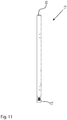
- the side part 13 is also in Figure 11 shown with the inlet opening 15 and the perforated plate 35.
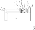
- FIG 12 the side part 13 is shown without thermal insulation 21 and the view falls on a labyrinth which is open as a result and which is formed by an inlet labyrinth 39 and a foreign labyrinth 33.
- the inlet labyrinth 39 and the outlet labyrinth 33 are used for sound insulation and acoustical decoupling of the machine room from the installation room. This also prevents liquids from entering.
- An outside air volume flow V ARL can flow into the ventilation duct 30 through the inlet opening 15 and is conveyed to the fan 40.
- the fan 40 has an outlet opening 17 which is connected to the machine room 11 of the heat pump 1.
- the outside air volume flow V ARL is conducted via the pressure side 42 into the outlet labyrinth 33, where the outside air volume flow V ARL flows out again into the installation room 2 via the perforated plate 35.
- the inlet opening 15 is advantageously arranged close to the floor and the perforated plate 35 points upwards.
- the mixing portal 61 is shown in more detail.
- the mixing portal 61 is in this embodiment in a direction of the outside air volume flow behind an air line 31.
- the mixing portal 61 is between the air line 31 and the suction side 41 of the fan 40.
- the outside air volume flow V ⁇ ARL flows through the inlet opening 15 to air connection 31 and through the air connection 31 to the mixing portal 61.
- a refrigerant volume flow V ⁇ ⁇ continues to flow to the mixing portal 61 and is conveyed through the suction side 41 of the fan 40 to the pressure side 42 of the fan 40, after which there is the further venting channel 30 and a mixed volume flow of refrigerant and outside air continues to flow through the vent duct 30.
- the fan 40 is sealed with a seal 43.
- the air line 31 is formed by an opening or a cutout in the seal.
- the air line 31 is limited by the fan 40, edges of the seal 43 and by the underside 18.
- the mixing portal 61 is advantageously a zone or area in which outside air and, in the event of a leak, refrigerant meet.
- the mixing portal 61 is located behind the air line 31 and in front of the suction side 41. If a Venturi nozzle is used, an indirect negative pressure is generated in the Venturi nozzle, not directly by the fan or the suction side of the fan 40, but by the Venturi nozzle area, where a flow acceleration and thus a pressure drop is generated. If a Venturi nozzle insert or a Venturi nozzle is used, the pressure drop in the Venturi nozzle is located in the ventilation duct 30 in the mixing portal 61, where outside air and, in the event of a leak, refrigerant come together.
Landscapes
- Engineering & Computer Science (AREA)
- Chemical & Material Sciences (AREA)
- Combustion & Propulsion (AREA)
- Mechanical Engineering (AREA)
- General Engineering & Computer Science (AREA)
- Physics & Mathematics (AREA)
- Thermal Sciences (AREA)
- Other Air-Conditioning Systems (AREA)
Abstract
Description
- Die vorliegende Erfindung betrifft eine Wärmepumpe, insbesondere eine Wärmepumpe, die für die Aufstellung in einem Aufstellraum ausgebildet ist.
- In jüngerer Vergangenheit verstärkt sich die Suche nach klimafreundlichen Kältemitteln. Nachteilig an vielen klimafreundlichen Kältemitteln ist jedoch deren Brennbarkeit. Ein Einsatz derartiger Kältemittel, beispielsweise in Wärmepumpen, führt daher zu besonderen Anforderungen an die Sicherheit. Um zu gewährleisten, dass es nicht zu einer ungewollten Entzündung von eventuell aus einem Kältekreis austretendem Kältemittel kommt, ist ein Mindestvolumen beziehungsweise ein Mindestraum vorgeschrieben, in dem sich das austretende Kältemittel verteilt, um eine ausreichende Durchmischung zu erreichen.
- Brennbares Kältemittel muss demnach bei möglicher Leckage im Kältekreis sicher aus der Wärmepumpe gefördert werden. Dabei ist es zielführend das Kältemittel so hoch wie möglich in den Aufstellraum zu fördern. Dies senkt die geforderte Mindestfläche, die der Aufstellraum haben muss um eine ausreichende Durchmischung zu gewährleisten damit die Kältemittelkonzentration in der Luft nicht mehr entflammbar ist. Dazu gibt es laut Norm 60335-2-40 drei Varianten:
- 1. Kältemittel tritt in gewisser Höhe selbstständig (ohne Lüfter) aus der Wärmepumpe aus. Hierbei ist ausschließlich die Kältemittel-Austrittshöhe für die minimale Aufstellraumgröße entscheidend. Die Austrittshöhe ist definiert als die Höhe, ab der die Summe aller Öffnungen im Gerät 5 cm2 überschreiten. Je höher die Austrittshöhe ist, umso kleiner ist die minimale Aufstellraumgröße in Quadratmetern (m2). Diese Lösung ist kostengünstig, erfordert jedoch regelmäßig zu große Aufstellräume, so dass die praktische Umsetzung nicht möglich ist. Sollte der Aufstellraum zu klein sein, ist vorteilhaft die Austrittshöhe mit einer Verlängerung, wie einem Schnorchel, zu erweitern.
- 2. Kältemittel wird durch einen Lüfter in den Aufstellraum gefördert: Hierbei ist die Höhe, die das Medium erreicht bevor es wieder absinkt, maßgeblich. Je höher das Kältemittel strömt, umso kleiner ist die minimale Aufstellraumgröße in Quadratmetern (m2). Zusätzlich muss ein gewisser Mindestvolumenstrom von dem Lüfter realisiert werden. Alle anderen Geräteöffnungen dürfen in Summe 5 cm2 nicht überschreiten. Der hierfür eingesetzte Lüfter ist jedoch mit Kosten verbunden, so dass nach Möglichkeit, nämlich falls aufgrund der Aufstellraumgröße nicht notwendig, darauf verzichtet wird.
- 3. Kältemittel wird mit einem Lüfter aus dem Aufstellraum nach draußen gefördert. Hierbei ist ausschließlich der Mindestvolumenstrom ausschlaggebend. Die übrigen Geräteöffnungen dürfen auch hier in Summe 5 cm2 nicht überschreiten. Diese Variante senkt die minimale Aufstellraumgröße auf 0 m2, so dass jeder beliebige Aufstellort geeignet ist. Grundsätzlich ist jedoch hiermit ein Wanddurchbruch verbunden, der aufwändig ist.
- Zurzeit werden deshalb brennbare Kältemittel hauptsächlich in außenaufgestellten Wärmepumpen verwendet oder die Kältemittelmenge so stark reduziert, dass eine Leckage keinen signifikanten Schaden anrichten kann. Bei innenaufgestellten Wärmepumpen gibt die Norm die benannten drei Varianten an, gemäß denen das Kältemittel austreten gelassen wird. Verschiedene Wärmepumpen sind demnach nur für bestimmte Aufstellorte, genauer Größen von Aufstellräumen, einsetzbar.
- Vor diesem Hintergrund war es eine Aufgabe der vorliegenden Erfindung, eine Wärmepumpe anzugeben, die an die Bedingungen des Aufstellraumes anpassbar ist. Ebenfalls war es eine Aufgabe der vorliegenden Erfindung, eine verbesserte Sicherheitslösung für innenaufgestellte Wärmepumpen, die brennbares Kältemittel einsetzen, bereitzustellen. Jedenfalls soll eine alternative Wärmepumpe angegeben werden.
- Erfindungsgemäß wird eine Wärmepumpe, insbesondere Wärmepumpe zur Aufstellung in einem Aufstellraum, mit einem Gehäuse, einem in einem Maschinenraum angeordneten Kältekreis mit einem brennbaren Kältemittel, insbesondere R454C, und einem Entlüftungskanal zur Ausleitung von austretendem Kältemittel vorgeschlagen. Dem Entlüftungskanal ist ein Lüfter zugeordnet, wobei der Entlüftungskanal mit einer Luftleitung verbunden ist, die dazu geeignet ist, Aufstellraumluft aus dem Aufstellraum zu führen. Weiterhin weist die Luftleitung in ein Mischportal, wobei das Mischportal mit dem Entlüftungskanal und dem Maschinenraum verbunden ist und dazu geeignet ist Aufstellraumluft und Maschinenraumluft zusammen zu bringen.
- Erfindungsgemäß wird weiterhin eine Wärmepumpe, insbesondere Wärmepumpe zur Aufstellung in einem Aufstellraum, mit einem Gehäuse, einem in einem Maschinenraum angeordneten Kältekreis mit einem brennbaren Kältemittel, insbesondere R454C, und einem Entlüftungskanal zur Ausleitung von austretendem Kältemittel vorgeschlagen. Die Wärmepumpe weist einen Lüfter auf, der mit dem Entlüftungskanal verbunden ist. Eine Druckseite des Lüfters ist einem Endabschnitt zugeordnet. Eine Saugseite des Lüfters ist dem Maschinenraum zugeordnet und die Saugseite hat eine Luftverbindung zum Aufstellraum.
- Der Lüfter ist vorteilhaft im Entlüftungskanal angeordnet. Eine Saugseite ist zu einer Austrittsöffnung gerichtet, die eine Öffnung im Gehäuse darstellt und wodurch im Fehlerfall austretendes Kältemittel, aus dem Kältemittelkreislaufs, zum Lüfter gesaugt wird. Das Kältemittel wird dann vom Lüfter durch den Entlüftungskanal zu einem Endabschnitt geleitet und aus der Wärmepumpe, bzw. aus dem Maschinenraum in den Aufstellraum gepustet. Vorteilhaft ist die Saugseite des Lüfters weiterhin mittels einer Luftleitung mit dem Aufstellraum verbunden. Vorteilhaft weist der Entlüftungskanal hierzu eine Eintrittsöffnung auf, wodurch Aufstellraumluft zum Lüfter strömen kann.
Da der Lüfter für einen permanenten Betrieb ausgelegt ist, und auch permanent, also auch, wenn die Wärmepumpe ausgeschaltet ist in Betrieb ist, wird dauerhaft Aufstellraumluft über die Saugseite des Lüfters angesaugt. Dauerhaft und permanent findet demnach ein Volumenstrom von Aufstellraumluft durch die Eintrittsöffnung, durch die Luftverbindung zur Saugseite des Lüfters statt. Dort wird die Aufstellraumluft durch den Luftkanal weiter zum Endabschnitt gefördert. Nur im Leckagefall, wenn Kältemittel aus dem Kältemittelkreislauf austritt, wird dieses Kältemittel durch eine Austrittsöffnung des Maschinenraums zur Saugseite des Lüfters gefördert. Vorteilhaft wird hierbei die Außenraumluft und das Kältemittel in einem Mischportal, welches sich vor der Saugseite des Lüfters befindet zusammengeführt. Hier erfolgt vorteilhaft zumindest eine erste Vermischung von Außenraumluft und Kältemittel. Weiter im Luftkanal strömen im Leckagefall Kältemittel und Außenraumluft und vermischen sich weiter zu einem Mischvolumenstrom. - In einem anderen vorteilhaften Fall ist die Saugseite des Lüfters nur mit dem Aufstellraum verbunden und saugt permanent Aufstellraumluft direkt an. Eine Verbindung der Austrittsöffnung mit dem Lüfter ist vorteilhaft nicht vorgesehen. Dann strömt die Außenraumluft im Entlüftungskanal weiter zu einer Venturidüse. In der Venturidüse erfolgt eine Beschleunigung des Volumenstroms und dadurch ein Druckabfall. Die Venturidüse weist eine Luftverbindung auf, die vorteilhaft eine Beschleunigungseinheit aufweist. Hier ist die Venturidüse vorteilhaft über die Austrittsöffnung mit dem Maschinenraum verbunden und durch den Unterdruck in der Venturidüse wird ein Unterdruck im Maschinenraum erzeugt. In einem Leckagefall wird durch den Unterdruck in der Venturidüse durch die Austrittsöffnung, Kältemittel aus dem Maschinenraum abgesaugt. Das Mischportal ist der Bereich, wo die Außenraumluft mit dem Kältemittel zusammentrifft. Durch die Luftverbindung strömt somit Außenraumluft, die mit Kältemittel zusammengebracht wird, was hier vorteilhaft in der Venturidüse im Mischportal erfolgt. Weiter strömt im Leckagefall ein Mischvolumen aus der Venturidüse heraus und weiter im Entlüftungskanal zum Endabschnitt.
Das Mischportal ist eine Zone, wo Außenraumluft und im Leckagefall Kältemittel zusammentreffen.
Das Mischportal wird vorteilhaft vom Ende der Luftleitung und der Saugseite des Lüfters gebildet.
Gemäß einem anderen Gedanken der Erfindung ist das Mischportal in der Venturidüse, oder nach der Venturidüse durch die Luftleitung der Venturidüse und der Austrittsöffnung gebildet.
Im Mischportal erfolgt vorteilhaft eine Vermischung von Kältemittel und Aufstellraumluft. Nach dem Verlassen des Entlüftungskanals, vorteilhafter Weise durch ein Lochblech wird das Kältemittel weiter mit der Außenluft vermischt.
Gemäß einem vorteilhaften Verfahren zur Sicherung einer in einem Aufstellraum aufgestellten Wärmepumpe wird mit einem Außenraumluftstrom ein Unterdruck in einem Maschinenraum des Gehäuses der Wärmepumpe erzeugt, wobei der Lüfter permanent läuft und aus dem Aufstellraum permanent Aufstellraumluft angesaugt wird. Im Falle einer Leckage wird Kältemittel eines Kältemittelkreislaufs aus dem Maschinenraum abgesaugt und mit Aufstellraumluft aus dem Aufstellraum vermischt. Das Kältemittel wird aus dem Maschinenraum vorteilhaft zumindest mittelbar vom Lüfter angesaugt und das Gemisch aus Kältemittel aus dem Maschinenraum und Aufstellraumluft wird wieder in den Aufstellraum befördert.
Vorteilhaft wird aus dem Aufstellraum im Leckagefall vom Lüfter, permanent ein Kältemittel-Luftgemisch durch den Entlüftungskanal gefördert, auch wenn das Kältemittel bereits aus dem Maschinenraum in den Aufstellraum gefördert wurde, wobei die Förderung von Luft und Kältemittel im Leckagefall dauerhaft weiter erfolgt. Damit wird die Luft und/oder das Kältemittel im Aufstellraum permanent bewegt und mit der dortigen Aufstellraumluft gemischt.
Der permanente Lauf des Lüfters schließ vorteilhaft mögliche Kalibrierzyklen, in denen er langsam läuft mit ein. Auch ein taktend betriebener Lüfter, der immer wieder aus- und eingeschaltet wird, fällt unter den Begriff "permanent laufend". Damit ist umfasst, dass der Lüfter in einer Zeiteinheit ein Volumen von Aufstellraumluft und/oder Kältemittel und/oder Kältemittel-Aufstellraumluft umwälzt und/oder einen Unterdruck im Maschinenraum erzeugt. Ein in einem Ein-Aus betrieb taktender Lüfter fällt vorteilhaft ebenfalls unter den Begriff permanenter Betrieb, auch wenn der Lüfter kurzzeitig zum stehen kommt, insbesondere für einen Kalibier- oder Sicherheitsmodus. Auch fällt unter "permanenter Betrieb" ein in der Drehzahl variierender Lüfter.
Weiterhin vorteilhaft ist es die Drehzahl des Lüfters oder sein Fördervermögen abhängig von einer Leckagedetektion einzustellen. Wird eine Leckage detektiert, dann wird vorteilhaft die Drehzahl oder der Fördervolumenstrom des Lüfters erhöht.
Vorteilhaft ist eine Leckagedetektion vorgesehen, womit ein Fehlersignal angezeigt und vorteilhaft per E-Mail versendet wird und die Wärmepumpe abgeschaltet wird, vorteilhaft spannungsfrei geschaltet wird, wobei der Lüfter weiterläuft, vorteilhaft mit Netz- und/oder Akkubetrieb.
Erfindungsgemäß ist es somit möglich, eine Wärmepumpe zunächst standardmäßig nach der oben beschriebenen Variante 1 zu betreiben, das heißt, das Kältemittel in einem an einem Ende des Entlüftungskanals befindlichen Endabschnitt selbstständig ausströmen zu lassen.
Der Entlüftungskanal kann als ein außen an der Wärmepumpe angebrachter Rechteckkanal ausgeführt sein. Vorteilhaft ist ein in eine Seitenwand, Rückwand oder Vorderwand integrierter Entlüftungskanal. - Gemäß einem weiteren Gedanken der Erfindung ist der Entlüftungskanal in eine Seitenwand, Vorderwand oder Rückwand der Wärmepumpe integriert, wo vorteilhaft auch eine Wärmedämmung oder Schallisolierung vorgesehen ist.
- Vorteilhaft ist ein Entlüftungskanal vor und oder hinter dem Lüfter mit einem Labyrinth vorgesehen, vor dem Lüfter insbesondere ein Einlasslabyrinth und nach dem Lüfter insbesondere ein Auslasslabyrinth. Die Saugseite des Lüfters ist über die Austrittsöffnung mit dem Maschinenraum verbunden und über die Eintrittsöffnung mit dem Aufstellraum. Die Druckseite des Lüfters ist mit dem Auslasslabyrinth verbunden. In die Eintrittsöffnung strömt somit ein permanenter Volumenstrom von Außenraumluft und im Leckagefall strömt zusätzlich ein Volumenstrom von Kältemittel zur Saugseite.
- Vorteilhaft ist hinter dem Auslasslabyrinth das Mischportal gebildet, vorteilhaft primär vor der Saugseite des Lüfters. Das Mischportal ist vorteilhaft eine Zone, wo die Außenraumluft und das gegebenenfalls bei einer Leckage austretende Kältemittel aufeinandertreffen. Es erfolgt dort auch vorteilhaft eine erste Mischung von Außenraumluft und Kältemittel. Ein Volumenstrom von Kältemittel und Außenraumluft wird dann durch die Saugseite in den Lüfter gesaugt und dort sowie vorteilhaft im nachfolgenden Auslasslabyrinth weiter gemischt und strömt als Misch-Volumenstrom zum Endabschnitt, wo vorteilhafter Weise ein Lochblech vorgesehen ist, durch den der Misch-Volumenstrom in den Aufstellraum strömt.
- Vorteilhaft ist die Eintrittsöffnung in Bodennähe angeordnet um das, in der Regel eine höhere Dichte aufweisende, brennbare Kältemittel aus dem Bodenbereich des Aufstellraums abzusaugen und durch den Entlüftungskanal in eine höhere Zone des Aufstellraums zu fördern.
- Der Entlüftungskanal weist den Endabschnitt mit einer vorgesehenen Höhe von wenigstens etwa 80 cm oder einen Wert von mehr als 80 cm über dem Boden auf. Mittels einem aufsteckbaren Luftkanal kann die Austrittshöhe des Misch-Volumenstroms bzw. die Austrittshöhe des Kältemittels aus dem Endabschnitt erhöht werden. Soweit erforderlich weisen Luftkanäle, die auf den Entlüftungskanal aufgesteckt oder aufgebracht werden eine Länge von wenigstens 30 cm und mehr auf, um den Endabschnitt in eine höhere Lage im Aufstellraum zu bringen, vorteilhaft etwa 1,50 m oder mehr.
- In einem weiteren vorteilhaften Ausführungsbeispiel ist der Entlüftungskanal durch ein im Maschinenraum der Wärmepumpe oder generell in der Wärmepumpe oder an der Wärmepumpe verlegtes Rohr, insbesondere auch flexibles Rohr gebildet oder einen Schlauch gebildet. Auch hierbei kann das Mischportal durch eine Venturidüse gebildet sein, welche vorteilhaft in dem Rohr oder Schlauch angeordnet ist und eine Verbindung zum Aufstellraumluft und zum Maschinenraum aufweist.
- Der Entlüftungskanal ist gemäß einem vorteilhaften Gedanken als Schlauch ausgebildet und weiterhin vorteilhaft mit dem Lüfter verbunden.
- Vorteilhaft weist das Gehäuse eine Austrittsöffnung auf und der Entlüftungskanal schließt an die Austrittsöffnung an. Der Entlüftungskanal weist eine verschließbare Aufnahme auf, die zur Aufnahme eines Lüfters ausgebildet ist.
- Zusätzlich ist jedoch in dem Entlüftungskanal, der sich an die Austrittsöffnung des Gehäuses anschließt und somit von außen zugänglich ist, eine verschließbare Aufnahme für den Lüfter bereitgestellt. Ohne großen Aufwand lässt sich demnach durch eine Nachrüstung, beispielsweise in Form eines Nachrüstkits, eines Lüfters vornehmen und die erfindungsgemäße Wärmepumpe auf die oben beschriebene Variante 2 erweitern. Somit ist es möglich, dass die gleiche Wärmepumpe für verschiedene Größen von Aufstellräumen vorbereitet ist und durch den einfach in der Aufnahme einzuführenden Lüfter anpassbar ist. Es müssen somit keine verschiedenen Wärmepumpen für verschiedene Größen von Aufstellräumen konstruiert werden.
- Die verschließbare Aufnahme ermöglicht, dass der Entlüftungskanal nur an einem der Austrittsöffnung gegenüberliegenden Ende, nicht jedoch im Bereich der Aufnahme undicht ist und das Ausströmen von Kältemittel im Bereich der Aufnahme unterbleibt.
- Vorzugsweise ist das Gehäuse mit Ausnahme der Austrittsöffnung dicht. In diesem Zusammenhang heißt "dicht" insbesondere, dass die Summe der Öffnungen kleiner als 5 cm2 beträgt oder vorteilhaft deutlich weniger als 2 cm2.
- Somit kann für die Berechnung der Mindestgröße des Aufstellraums die Höhe des Endes des Entlüftungskanals herangezogen werden, da weder der Entlüftungskanal noch das Gehäuse an niedriger liegender Stelle Öffnungen aufweisen, die in Summe größer als 5 cm2 betragen.
- Vorzugsweise ist der Entlüftungskanal als Flachkanal, insbesondere als Flachkanal in Rechteckform, ausgebildet.
- Ein Flachkanal hat den Vorteil, dass besonders viel Querschnittsfläche erreichbar ist, ohne dass der Entlüftungskanal weit über das Gehäuse der Wärmepumpe hervorsteht. Anders ausgedrückt kann ein Flachkanal besonders gut an das Gehäuse der Wärmepumpe anliegen und demnach die Abmessungen der Wärmepumpe nicht übermäßig erhöhen.
- Vorzugsweise weist ein Ende des Entlüftungskanals Kopplungsmittel zum Anschluss eines externen Luftkanals auf. Besonders bevorzugt handelt es sich bei dem Entlüftungskanal hierfür um einen in Standardmaßen ausgefertigten Luftkanal, so dass eine Kopplung mit weiteren erhältlichen Luftkanalelementen möglich ist.
- Der externe Luftkanal ermöglicht insbesondere eine Erweiterung der Wärmepumpe auf die Variante 3 des oben angesprochenen Sicherheitskonzepts. So kann der Entlüftungskanal bis nach außen aus dem Aufstellraum heraus erweitert werden und eine Ausleitung von eventuell austretendem Kältemittel aus dem Aufstellraum erreicht werden. Damit sinkt die Mindestgröße des Aufstellraums in dieser Variante auf 0 m2.
- Vorzugsweise weist der Entlüftungskanal eine Schalldämmung in seinem Inneren auf.
- Die Öffnung in dem dichten und schallisolierten Gehäuse der Wärmepumpe, die durch die Austrittsöffnung entsteht, sorgt dafür, dass Geräusche aus dem Inneren der Wärmepumpe durch den Entlüftungskanal nach außen treten können. Durch die Ausführung des Entlüftungskanals mit einer Schalldämmung wirkt der Entlüftungskanal vorzugsweise als Kulissenschalldämpfer und kann demnach die außerhalb der Wärmepumpe messbaren Geräusche reduzieren.
- Die Austrittsöffnung ist an einer Unterseite des Gehäuses angeordnet und der Entlüftungskanal verläuft von der Austrittsöffnung unterhalb des Gehäuses zu einer Rückseite des Gehäuses und hinter der Rückseite nach oben.
- Durch diese vorteilhafte Führung des Entlüftungskanals wird erreicht, dass ein Ende des Entlüftungskanals weit oben liegt, beispielsweise im Bereich der Oberkante des Gehäuses oder sogar darüber. Damit kann die Mindestgröße des Aufstellraumes auch bereits ohne den bereitgestellten Lüfter reduziert werden.
- Zusätzlich ermöglicht die Form, die demnach den Luftstrom zweimal, einmal von vertikal in Richtung der Austrittsöffnung zu horizontal unter dem Gehäuse, und dann zu vertikal nach oben im Bereich der Hinterkante, umlenkt, dass auch ein entstehender Schall durch die zweifache Umlenkung besonders gut abgeschirmt wird.
- Vorzugsweise ist die verschließbare Aufnahme derart angeordnet, dass sie von einer Vorderseite des Gehäuses der Wärmepumpe zugänglich ist.
- Die verschließbare Aufnahme kann sich beispielsweise unmittelbar an die Entlüftungsöffnung anschließen und an eine Bodenfläche des Gehäuses anschließen. Dann kann die verschließbare Aufnahme unterhalb des Gehäuses, das beispielsweise auf Standfüßen steht, zugänglich sein und ein zu installierender Lüfter im Bedarfsfall von vorne in die Aufnahme eingeführt werden. Auch eine Wartung und Instandhaltung des Lüfters ist einfach möglich, da die Aufnahme zur Wartung des Lüfters ebenfalls von der Vorderseite der Wärmepumpe aus zugänglich ist.
- Vorzugsweise weist die Wärmepumpe ferner einen Lüfter, insbesondere einen Radiallüfter, auf, der in der Aufnahme des Entlüftungskanals aufgenommen ist.
- Vorzugsweise ist die Wärmepumpe als innenaufgestellte Sole-Wasser-Wärmepumpe oder Wasser-Wasser-Wärmepumpe ausgebildet. Gegenüber Luft-Wasser-Wärmepumpen ist ein relevanter Unterschied, dass Sole-Wärmepumpen üblicherweise von sich aus, keine Lüfter aufweisen, die zur Förderung von eventuell austretendem Kältemittel aus dem Aufstellraum heraus einsetzbar sind, so dass das Vorsehen zusätzlicher Elemente zum Gewährleisten der Sicherheitsanforderungen nötig ist.
- Erfindungsgemäß wird ferner ein Verfahren zum Konfigurieren einer erfindungsgemäßen innenaufgestellten Wärmepumpe vorgeschlagen, wobei das Verfahren in Abhängigkeit einer Größe eines Aufstellraumes aufweist: Verlängern eines Entlüftungskanals der Wärmepumpe in eine größere Höhe in dem Aufstellraum; Bereitstellen eines Lüfters, insbesondere Radiallüfters in einer Aufnahme des Entlüftungskanals, und/oder Verlängern des Entlüftungskanals aus dem Aufstellraum heraus.
- Je nach Größe des Aufstellraumes ist es demnach möglich, die gleiche Wärmepumpe gemäß der definierten 1., 2. oder 3. Variante zu betreiben. Die Wärmepumpe ist demnach unabhängig von einer Größe des Aufstellraumes sicher betreibbar. Gleichzeitig wird vermieden, dass unnötige Sicherheitskomponenten die Komplexität der Wärmepumpe erhöhen, falls diese aufgrund der Größe des Aufstellraumes nicht benötigt werden. Dies betrifft insbesondere den nachrüstbaren Lüfter und die nachrüstbare Verlängerung des Entlüftungskanals. Somit wird eine den Umständen angemessene, besonders einfache Wärmepumpe erhalten.
- Vorteilhaft wird der Lüfter mit einer Leistung von ca. 2 W oder weniger betrieben. Aber auch höhere Leistungen sind vorteilhaft, abhängig insbesondere vom Gegendruck im Entlüftungskanal. Vorteilhaft hat der Lüfter eine Bemessungsleistung von etwa 0,5 W bis 20 W. Ein vorteilhaftes Fördervolumen liegt zwischen 10 m3/h und 100 m3/h. Ein Fördervolumen von ca. 300 m3 kann vorteilhaft sein, insbesondere bei einer Leckage.
- Weitere Vorteile und Ausgestaltungen werden nachfolgend mit Verweis auf die beigefügten Zeichnungen beschrieben. Hierbei zeigen:
- Fig. 1, 2
- schematisch und exemplarisch perspektivische Ansichten einer erfindungsgemäßen Wärmepumpe,
- Fig. 3
- schematisch und exemplarisch eine Schnittansicht einer Ausführung der Wärmepumpe,
- Fig. 4
- schematisch und exemplarisch eine Schnittansicht einer weiteren Ausführung der Wärmepumpe und
- Fig. 5
- schematisch und exemplarisch eine Schnittansicht einer weiteren Ausführung der Wärmepumpe.
- Fig. 6
- Wärmepumpe schematisch mit einem Entlüftungskanal und einem Lüfter
- Fig. 7
- Wärmepumpe mit Entlüftungskanal und Luftkanal
- Fig. 8
- Wärmepumpe mit Venturidüse als Mischportal im Entlüftungskanal
- Fig. 9
- Wärmepumpe mit Mischportal Entlüftungskanal
- Fig. 10
- Seitenwand mit Entlüftungskanal und Lüfter
- Fig. 11
- Seitenwand mit Eintrittsöffnung
- Fig. 12
- Seitenwand mit Auslass und Einlasslabyrinth
- Fig. 13
- Abschnitt des Entlüftungskanals mit Lüfter und Mischportal
-
Figuren 1 und 2 zeigen schematisch und exemplarisch perspektivische Ansichten einer erfindungsgemäßen Wärmepumpe 1 aus unterschiedlichen Richtungen. Die Wärmepumpe 1 weist ein Gehäuse 10 mit einer Vorderseite 12, einem Seitenteil 13, einer Rückseite 14, einer Oberseite 16 und einer Unterseite 18 auf. Ein Deckel 20 lässt sich üblicherweise zum Warten und Konfigurieren der Wärmepumpe 1 öffnen und ermöglicht einen Zugriff auf die innenliegenden Komponenten. Anschlüsse 22 sind üblicherweise ebenfalls im Bereich der Oberseite 16 ausgebildet. In dem Gehäuse 10 ist ein nicht weiter dargestellter Kältekreis angeordnet. - Unterhalb des und hinter dem Gerät ist ein Entlüftungskanal 30 angeordnet. Der Entlüftungskanal 30 entspringt in einem Abschnitt 32, in dem das Gehäuse 10 eine Austrittsöffnung (vgl.
Fig. 3-5 ) aufweist, führt von dort nach hinten entlang des Bodens 18 des Gehäuses 10 und dann vertikal nach oben, hinter der Rückseite 14 des Gehäuses 10. An einem oberen Endabschnitt 34 des Entlüftungskanals 30 ist eine Öffnung ausgebildet, die Kopplungsmittel aufweist, die zum Anschluss eines externen Luftkanals 50 ausgebildet sind. In diesem Beispiel ist die besonders bevorzugte Dimensionierung des Entlüftungskanals 30 als rechteckiger Flachkanal gezeigt. Damit auf dem Entlüftungskanal 30 nicht das Gewicht der gesamten Wärmepumpe 1 aufliegt, weist die Wärmepumpe 1 zusätzlich an ihrem Boden 18 Standfüße 19 auf. - Von der Vorderseite 12 ist eine verschließbare Aufnahme 36 des Entlüftungskanals 30 zugänglich. Über die verschließbare Aufnahme 36 ist ein Lüfter montierbar, wie später mit Verweis auf
Figuren 4 und5 weiter beschrieben wird. -
Fig. 3 zeigt schematisch und exemplarisch einen Querschnitt durch die erfindungsgemäße Wärmepumpe 1. Nicht gezeigt ist in dieser Darstellung der Deckel 20, der das Gehäuse 10 nach oben abdichtet. InFigur 3 ist eine Austrittsöffnung 17 zu sehen, die in dem Boden des Gehäuses 10 bereitgestellt ist und direkt in das Innere der Aufnahme 36 des Entlüftungskanals führt. In dem Entlüftungskanal 30 ist ferner ein Schalldämmung 38 angeordnet. Der Entlüftungskanal 30 wirkt somit auch als Kulissenschalldämpfer um die entstehende Austrittsöffnung 17. An dem oberen Ende 34 des Entlüftungskanals 30 ist in diesem Ausführungsbeispiel ein externer Luftkanals 50 anschließbar. Verschiedene Ausführungen des externen Luftkanals 50 sind vergrößert inFig. 3 dargestellt. Hierbei handelt es sich vorzugsweise um Standardbauteile und Abmessungen von Lüftungskanälen, so dass die erfindungsgemäße Wärmepumpe 1 in vorteilhafter Weise mit bestehenden Lösungen kombinierbar ist. - In
Fig. 3 ist durch Pfeile angedeutet, welchen Weg das austretende Kältemittel bis zum Ende 34 des Entlüftungskanals 30 einnimmt. Mit dem externen Luftkanals 50 kann die Austrittshöhe weiter erhöht werden und dadurch die Mindestgröße des Aufstellraums stark verringert werden. Dies kann insbesondere dann geschehen, wenn der Aufstellraum ohne die Verlängerung mittels des externen Luftkanals 50 zu klein wäre. - Für den Fall, dass der Aufstellraum trotz Verlängerung mittels externen Luftkanals 50 zu klein ist, wird ein Lüfter 40, wie er schematisch und exemplarisch in
Fig. 4 gezeigt ist, ergänzend in die verschließbare Aufnahme 36 aufgenommen. Hierzu wird eine von der Vorderseite 12 zugängliche Klappe 37, die die verschließbare Aufnahme 36 verschließt, geöffnet, der Lüfter 40 eingefügt und die Klappe 37 anschließend verschlossen. Schließlich gibt es auch, vgl.Fig. 5 , eine Kombination aus Lüfter 40 und externem Luftkanal 50, mit der die Luft beispielsweise bis nach außen aus dem Aufstellraum geführt werden, wodurch sich die Mindestgrößer des Aufstellraumes auf 0 m2 verringert. - Der Lüfter 40 ist ein Radiallüfter, der 90° zur Ansaugrichtung ausbläst, und vorzugsweise in dem Entlüftungskanal 30 montiert wird. Durch die von der Vorderseite zugängliche Klappe 37 wird die Installation des Lüfters 40 erleichtert.
- Gemäß
Figur 6 ist ein Ausführungsbeispiel gezeigt, bei dem die Saugseite 41 des Lüfters 40 zu Austrittsöffnung 17 zeigt. Im Leckagefall wird durch die Saugseite 41 des Lüfters 40 ein Kältemittel Volumenstrom durch den Lüfter 40 in die Entlüftungsleitung 30 geleitet und durch die Entlüftungskanal 30 zum Endabschnitt 34. Im Ausführungsbeispiel weist der Endabschnitt 34 ein Loch Blech 35 auf. - Gemäß
Figur 7 ist ein Luftkanal 50 auf den Entlüftungskanal 30 aufgesteckt und verlängert den Entlüftungskanal um eine vorgegebene Höhe, so dass der Kältemittel Volumenstrom eine größere Höhe erreicht und im Aufstellraum in einer Höhe von vorteilhaft über 1,50 m über dem Boden des Aufstellraums ausströmt. - Bei den
Figuren 8 und9 erfolgt ein ständiger Außenraumluft-Volumenstrom V̇ ARL, der über eine Luftleitung zum Mischportal 61 strömt. GemäßFigur 8 befindet sich das Mischportal 61 in einer Venturidüse, die im Entlüftungskanal 30 angebracht ist. Die Venturidüse weist die Luftleitung 31, durch die der Außenraum-Luftstrom zumindest teilweise strömt und ist mit der Austrittsöffnung 17 verbunden. Somit befindet sich in der Venturidüse das Mischportal 61, wo der Außenraumluft-Volumenstrom V̇ ARL und das Kältemittel, welches im Leckagefall Austritt, zusammentreffen. - Gemäß
Figur 9 wird der Außenraumluft-Volumenstrom V̇ ARL über die Luftleitung 31 direkt vor die Saugseite des Lüfters 40 geführt. Im Leckagefall strömt ein Kältemittel-Volumenstrom V̇κ ebenfalls zum Mischportal und trifft dort auf die Außenraumluft. Eine erste Vermischung von Außenraumluft und Kältemittel erfolgt, wobei Kältemittel und Außenraumluft dann weiter durch die Saugseite 41 des Lüfters zur Druckseite 42 des Lüfters 40 gefördert werden und dann weiter durch den Entlüftungskanal 30. -
Figur 10 zeigt einen in ein Seitenteil 13 integrierten Entlüftungskanal 30 mit einer Wärmedämmung und oder Schallisolierung 21. Der Lüfter 40 ist im Entlüftungskanal angeordnet, wobei das Seitenteil 13 eine Eintrittsöffnung 15 aufweist, durch die Außenraumluft zur Saugseite des Lüfters strömen kann und es ist in einem Endabschnitt ein Lochblech 35 vorgesehen, durch die zumindest der Außenraumluft-Volumenstrom V̇ ARL wieder austreten kann. Das Seitenteil 13 ist ebenso inFigur 11 gezeigt mit der Eintrittsöffnung 15 und dem Lochblech 35. - In
Figur 12 ist das Seitenteil 13 ohne eine Wärmedämmung 21 gezeigt und der Blick fällt auf ein dadurch offenes Labyrinth, welches durch ein Einlasslabyrinth 39 und ein Auslandslabyrinth 33 gebildet ist. Das Einlasslabyrinth 39 und das Auslasslabyrinth 33 dient zur Schalldämmung und schalltechnischen Entkopplung des Maschinenraums vom Aufstellraum. Weiterhin wird hiermit der Eintritt von Flüssigkeiten verhindert. Durch die Eintrittsöffnung 15 kann ein Außenraumluft-Volumenstrom VARL in den Entlüftungskanal 30 einströmen und wird zum Lüfter 40 gefördert. Der Lüfter 40 weist eine Austrittsöffnung 17 auf, welche mit dem Maschinenraum 11 der Wärmepumpe 1 in Verbindung steht. Über die Druckseite 42 wird der Außenraumluft-Volumenstrom VARL in das Auslasslabyrinth 33 geleitet, wo der Außenraumluft-Volumenstrom VARL über das Lochblech 35 wieder in den Aufstellraum 2 ausströmt. Vorteilhaft ist die Eintrittsöffnung 15 nahe dem Boden angeordnet und das Lochblech 35 weist nach oben. - In
Figur 13 ist das Mischportal 61 näher gezeigt. Das Mischportal 61 befindet sich in diesem Ausführungsbeispiel in einer Richtung des Außenraumluft Volumenstroms hinter einer Luftleitung 31. das Mischportal 61 liegt zwischen der Luftleitung 31 und der Saugseite 41 des Lüfters 40. Der Außenraumluft-Volumenstrom V̇ ARL strömt durch die Eintrittsöffnung 15 zu Luftverbindung 31 und durch die Luftverbindung 31 zum Mischportal 61. Im Leckagefall strömt weiterhin ein Kältemittel-Volumenstrom V̇κ zum Mischportal 61 und wird durch die Saugseite 41 des Lüfters 40 zur Druckseite 42 des Lüfters 40 gefördert, wonach sich der weitere Entlüftungskanal 30 befindet und ein Mischvolumenstrom von Kältemittel und Außenraumluft weiter durch den Entlüftungskanal 30 strömt. Abgedichtet ist der Lüfter 40 mit einer Dichtung 43. Die Luftleitung 31 ist durch eine Öffnung oder einen Ausschnitt in der Dichtung gebildet. Begrenzt ist die die Luftleitung 31 durch den Lüfter 40, Ränder der Dichtung 43 und durch die Unterseite 18. - Das Mischportal 61 ist vorteilhaft eine Zone oder Bereich, in dem Außenraumluft und im Leckagefall Kältemittel zusammentreffen. Das Mischportal 61 befindet sich hinter der Luftleitung 31 und vor der Saugseite 41. Wird eine Venturidüse verwendet, so erfolgt eine mittelbare Unterdruckerzeugung in der Venturidüse, nicht direkt durch den Lüfter bzw. die Saugseite des Lüfters 40, sondern durch den Bereich Venturidüse, wo eine Strömungsbeschleunigung und somit ein Druckabfall erzeugt wird. An der Stelle des Druckabfalls in der Venturidüse befindet sich bei Verwendung eines Venturidüseneinsatzes oder einer Venturidüse, die im Entlüftungskanal 30 angeordnet in das Mischportal 61, wo dann Außenraumluft und im Leckagefall Kältemittel zusammentreffen.
Claims (18)
- Wärmepumpe (1), insbesondere Wärmepumpe (1) zur Aufstellung in einem Aufstellraum (2), mit- einem Gehäuse (10),- einem in einem Maschinenraum (11) angeordneten Kältekreis mit einem brennbaren Kältemittel, insbesondere R454C, und- einem Entlüftungskanal (30) zur Ausleitung von austretendem Kältemitteldadurch gekennzeichnet, dass
dem Entlüftungskanal (30) ein Lüfter (40) zugeordnet ist, wobei
der Entlüftungskanal (30) mit einer Luftleitung (31) verbunden ist, die dazu geeignet ist, Aufstellraumluft aus dem Aufstellraum (2) zu führen,
die Luftleitung (31) ein Mischportal (61) aufweist, wobei
das Mischportal (61) mit dem Entlüftungskanal (30) und dem Maschinenraum (11) verbunden ist, und dass geeignet ist Aufstellraumluft und Maschinenraumluft zusammen zu bringen. - Wärmepumpe (1), insbesondere Wärmepumpe (1) zur Aufstellung in einem Aufstellraum (2), mit- einem Gehäuse (10),- einem in einem Maschinenraum (11) angeordneten Kältekreis mit einem brennbaren Kältemittel, insbesondere R454C, und- einem Entlüftungskanal (30) zur Ausleitung von austretendem Kältemitteldadurch gekennzeichnet, dass
die Wärmepumpe (1) einen Lüfter (40) aufweist, der mit dem Entlüftungskanal (30) verbunden ist,
wobei eine Druckseite (42) des Lüfters (40) einem Endabschnitt (34) zugeordnet ist,
eine Saugseite (41) des Lüfters (40) dem Maschinenraum (11) zugeordnet ist und
die Saugseite (41) eine Luftverbindung (31) zum Aufstellraum (2) hat. - Wärmepumpe (1) nach Anspruch 1 oder 2, wobei das Gehäuse (10) mit Ausnahme der Austrittsöffnung (17), dem Endabschnitt (34) und/oder der Luftverbindung (31) dicht ist.
- Wärmepumpe (1) nach einem der vorstehenden Ansprüche, wobei die Saugseite an einer Austrittsöffnung (17) angebracht ist und der Entlüftungskanal 30 mit der Druckseite (41) zum Endabschnitt weist.
- Wärmepumpe (1) nach einem der vorstehenden Ansprüche, wobei die Eintrittsöffnung (15) die Austrittsöffnung (17) und der Endabschnitt mit dem Entlüftungskanal (30) verbunden sind.
- Wärmepumpe (1) nach einem der vorstehenden Ansprüche, wobei der Lüfter (40) im Luftkanal (50) liegt.
- Wärmepumpe (1) nach einem der vorstehenden Ansprüche, wobei der Entlüftungskanal (30) im Gehäuse (10) der Wärmepumpe (1), insbesondere zumindest teilweise in einem Gehäuseteil wie einem Seitenteil (13), einer Rückseite (14) und/oder einer Vorderseite (12) verläuft.
- Wärmepumpe (1) nach einem der vorstehenden Ansprüche, wobei der Entlüftungskanal (30) als Flachkanal, insbesondere als Flachkanal in Rechteckform, ausgebildet ist.
- Wärmepumpe (1) nach einem der vorstehenden Ansprüche, wobei ein Ende (34) des Entlüftungskanals (30) Kopplungsmittel zum Anschluss eines externen Luftkanals (50) aufweist.
- Wärmepumpe (1) nach einem der vorstehenden Ansprüche, wobei der Entlüftungskanal (30) eine Schalldämmung (38) in seinem Inneren aufweist.
- Wärmepumpe (1) nach einem der vorstehenden Ansprüche, wobei die Austrittsöffnung (17) an einer Unterseite (18') des Gehäuses (10) angeordnet ist und der Entlüftungskanal (30) von der Austrittsöffnung (17) unterhalb des Gehäuses (10) zu einer Rückseite (14) des Gehäuses (10) und hinter der Rückseite (14) nach oben verläuft.
- Wärmepumpe (1) nach einem der vorstehenden Ansprüche, wobei die verschließbare Aufnahme (36) derart angeordnet ist, dass sie von einer Vorderseite (12) des Gehäuses (10) der Wärmepumpe (1) zugänglich ist.
- Wärmepumpe (1) nach einem der vorstehenden Ansprüche, die ferner einen Lüfter, insbesondere einen Radiallüfter, aufweist, der in der Aufnahme des Entlüftungskanals (30) aufgenommen ist.
- Wärmepumpe (1) nach einem der vorstehenden Ansprüche, wobei die Wärmepumpe (1) als innenaufgestellte Sole-Wasser-Wärmepumpe (1) ausgebildet ist.
- Verfahren zum Konfigurieren einer innenaufgestellten Wärmepumpe (1) nach einem der vorstehenden Ansprüche, wobei das Verfahren in Abhängigkeit einer Größe eines Aufstellraumes aufweist:- Verlängern eines Entlüftungskanals (30) der Wärmepumpe (1) in eine größere Höhe in dem Aufstellraum,- Bereitstellen eines Lüfters (40'), insbesondere Radiallüfters in einer Aufnahme (36) des Entlüftungskanals (30), und/oder- Verlängern des Entlüftungskanals (30) aus dem Aufstellraum heraus.
- Verfahren zur Sicherung einer in einem Aufstellraum (2) aufgestellten Wärmepumpe (1) nach Anspruch 1, enthaltend die Verfahrensschritte, dass
mit einem Luftstrom ein Unterdruck in einem Maschinenraum (11) des Gehäuses (10) der Wärmepumpe (1) erzeugt wird,
mit dem permanent laufenden Lüfter (40) Aufstellraumluft aus einem Aufstellraum (2) angesaugt wird,
wobei im Falle einer Leckage Kältemittel eines Kältemittelkreislaufs aus dem Maschinenraum (11) abgesaugt wird und mit Aufstellraumluft aus dem Aufstellraum (2) vermischt wird, wobei
das Kältemittel aus dem Maschinenraum (11) zumindest mittelbar vom Lüfter (40) angesaugt wird und das Gemisch aus Kältemittel aus dem Maschinenraum (11) und Luft wieder in den Aufstellraum (2) befördert wird. - Verfahren nach Anspruch 16 enthaltend den Verfahrensschritt, das aus dem Aufstellraum (2) im Leckagefall permanent ein Kältemittel-Luftgemisch, wenn Kältemittel bereits aus dem Maschinenraum (11) in den Aufstellraum (2) gefördert wurde, vom Lüfter (40) angesaugt wird, wobei die Förderung von Luft und Kältemittel im Leckagefall dauerhaft weiter erfolgt.
- Verfahren nach einem der Ansprüche 15, 16 oder 17 enthaltend den Verfahrensschritt, dass eine Leckagedetektion im Falle einer Leckage erfolgt, insbesondere ein Fehlersignal angezeigt und vorteilhaft versendet wird und die Wärmepumpe (1) abgeschaltet wird, der Lüfter (40) jedoch weiterläuft.
Priority Applications (1)
| Application Number | Priority Date | Filing Date | Title |
|---|---|---|---|
| EP20161643.0A EP3875862A1 (de) | 2020-03-06 | 2020-03-06 | Wärmepumpe |
Applications Claiming Priority (1)
| Application Number | Priority Date | Filing Date | Title |
|---|---|---|---|
| EP20161643.0A EP3875862A1 (de) | 2020-03-06 | 2020-03-06 | Wärmepumpe |
Publications (1)
| Publication Number | Publication Date |
|---|---|
| EP3875862A1 true EP3875862A1 (de) | 2021-09-08 |
Family
ID=69902997
Family Applications (1)
| Application Number | Title | Priority Date | Filing Date |
|---|---|---|---|
| EP20161643.0A Pending EP3875862A1 (de) | 2020-03-06 | 2020-03-06 | Wärmepumpe |
Country Status (1)
| Country | Link |
|---|---|
| EP (1) | EP3875862A1 (de) |
Cited By (5)
| Publication number | Priority date | Publication date | Assignee | Title |
|---|---|---|---|---|
| WO2023232504A1 (en) * | 2022-05-30 | 2023-12-07 | Bdr Thermea Group B.V. | Enclosure for a heat pump |
| EP4361518A1 (de) * | 2022-10-27 | 2024-05-01 | BDR Thermea Group B.V. | Gehäuse für eine wärmepumpe |
| EP4686899A1 (de) | 2024-08-02 | 2026-02-04 | BDR Thermea Group B.V. | Steuergerät, verfahren, computerprogrammprodukt und nicht transitorisches computerlesbares medium zur überwachung von kältemittelleckagen, wärmepumpe mit diesem steuergerät |
| EP4686898A1 (de) | 2024-08-02 | 2026-02-04 | BDR Thermea Group B.V. | Steuergerät, verfahren, computerprogrammprodukt und nicht transitorisches computerlesbares medium zur überwachung von kältemittelleckagen, wärmepumpe mit diesem steuergerät |
| WO2026027765A1 (en) | 2024-08-02 | 2026-02-05 | Bdr Thermea Group B.V. | Controller for monitoring leakage of refrigerant |
Citations (4)
| Publication number | Priority date | Publication date | Assignee | Title |
|---|---|---|---|---|
| EP3156741A1 (de) * | 2014-06-13 | 2017-04-19 | Mitsubishi Electric Corporation | Wärmepumpenvorrichtung |
| FR3070755A1 (fr) * | 2017-09-07 | 2019-03-08 | Bernier Developpement | Dispositifs de securite pour installations frigorifiques et pompes a chaleur utilisant des fluides frigorigenes toxiques ou inflammables |
| DE202017006578U1 (de) * | 2017-12-22 | 2019-03-25 | Thomas Roggenkamp | Klimaschrank |
| EP3578895A2 (de) * | 2018-06-05 | 2019-12-11 | Vaillant GmbH | Sicherheitsspülvorrichtung für ein kältekreisgehäuse |
-
2020
- 2020-03-06 EP EP20161643.0A patent/EP3875862A1/de active Pending
Patent Citations (4)
| Publication number | Priority date | Publication date | Assignee | Title |
|---|---|---|---|---|
| EP3156741A1 (de) * | 2014-06-13 | 2017-04-19 | Mitsubishi Electric Corporation | Wärmepumpenvorrichtung |
| FR3070755A1 (fr) * | 2017-09-07 | 2019-03-08 | Bernier Developpement | Dispositifs de securite pour installations frigorifiques et pompes a chaleur utilisant des fluides frigorigenes toxiques ou inflammables |
| DE202017006578U1 (de) * | 2017-12-22 | 2019-03-25 | Thomas Roggenkamp | Klimaschrank |
| EP3578895A2 (de) * | 2018-06-05 | 2019-12-11 | Vaillant GmbH | Sicherheitsspülvorrichtung für ein kältekreisgehäuse |
Cited By (6)
| Publication number | Priority date | Publication date | Assignee | Title |
|---|---|---|---|---|
| WO2023232504A1 (en) * | 2022-05-30 | 2023-12-07 | Bdr Thermea Group B.V. | Enclosure for a heat pump |
| EP4361518A1 (de) * | 2022-10-27 | 2024-05-01 | BDR Thermea Group B.V. | Gehäuse für eine wärmepumpe |
| EP4686899A1 (de) | 2024-08-02 | 2026-02-04 | BDR Thermea Group B.V. | Steuergerät, verfahren, computerprogrammprodukt und nicht transitorisches computerlesbares medium zur überwachung von kältemittelleckagen, wärmepumpe mit diesem steuergerät |
| EP4686898A1 (de) | 2024-08-02 | 2026-02-04 | BDR Thermea Group B.V. | Steuergerät, verfahren, computerprogrammprodukt und nicht transitorisches computerlesbares medium zur überwachung von kältemittelleckagen, wärmepumpe mit diesem steuergerät |
| WO2026027765A1 (en) | 2024-08-02 | 2026-02-05 | Bdr Thermea Group B.V. | Controller for monitoring leakage of refrigerant |
| WO2026027766A1 (en) | 2024-08-02 | 2026-02-05 | Bdr Thermea Group B.V. | Heat pump with malfunction detection system |
Similar Documents
| Publication | Publication Date | Title |
|---|---|---|
| EP3705799B1 (de) | Wärmepumpe | |
| EP4194769B1 (de) | Kältemittelanlage sowie kältemittelmodul | |
| EP4050284B1 (de) | Wärmepumpe | |
| DE3502000A1 (de) | Dieselaggregat | |
| DE102022123440A1 (de) | Serviceanschluss für ein Wärmepumpengehäuse | |
| EP2028419B1 (de) | Abgasvorrichtung für eine Brenneinrichtung in einem Fahrzeug | |
| EP2500663A1 (de) | Rauchschutzanlage | |
| EP3370491B1 (de) | Anordnung eines kühlsystems zur kühlung mindestens eines, in einem raum angeordneten serverschranks | |
| DE2036295A1 (de) | Flüssigkeitsringverdichter mit Geräusch dampfung | |
| DE19834270C2 (de) | Ventilatorkonvektor | |
| DE102018104042A1 (de) | Belüftungsvorrichtung | |
| DE102014107666A1 (de) | Drainagesystem zur ableitung von wasser aus einem lufteinlass und einem luftverteilungsgehäuse einer klimaanlage | |
| DE4341784A1 (de) | Anordnung zur Erzeugung zweier gegenläufiger Luftschleier | |
| AT500559A1 (de) | Raumlufttechnische einrichtung | |
| EP4707688A1 (de) | Zündfähigkeitsverhinderung für kältemittel in ausseneinheit | |
| DE102024132095A1 (de) | Multifunktionale Außeneinheit für ein Wärmeverschiebungssystem | |
| DE102017219637A1 (de) | Schienenfahrzeug mit Entlüftung für elektrische Geräte | |
| DE102014013733B4 (de) | Verdichter für ein System zur Trocknung von Dämmschichten von Fußböden im Unterdruckverfahren | |
| DE102022123787A1 (de) | Kühl- und/oder Gefriergerät | |
| DE3900170C2 (de) | Verfahren und Vorrichtung zur Verminderung des Schaumvolumens über einer Flüssigeit in einem Behälter | |
| DE102023130458A1 (de) | Wärmepumpensystem, Luftführungsanordnung für ein Wärmepumpensystem und Verfahren zum Betreiben eines Wärmepumpensystems | |
| WO2008068221A1 (de) | Dampfbügeleisen | |
| DE202018102295U1 (de) | Labor-Saughaube | |
| EP3050412B1 (de) | Anordnung sowie verfahren zum kühlen eines raums | |
| DE202024105743U1 (de) | Sensorvorrichtung, insbesondere Schwergassensorvorrichtung |
Legal Events
| Date | Code | Title | Description |
|---|---|---|---|
| PUAI | Public reference made under article 153(3) epc to a published international application that has entered the european phase |
Free format text: ORIGINAL CODE: 0009012 |
|
| STAA | Information on the status of an ep patent application or granted ep patent |
Free format text: STATUS: THE APPLICATION HAS BEEN PUBLISHED |
|
| AK | Designated contracting states |
Kind code of ref document: A1 Designated state(s): AL AT BE BG CH CY CZ DE DK EE ES FI FR GB GR HR HU IE IS IT LI LT LU LV MC MK MT NL NO PL PT RO RS SE SI SK SM TR |
|
| STAA | Information on the status of an ep patent application or granted ep patent |
Free format text: STATUS: REQUEST FOR EXAMINATION WAS MADE |
|
| 17P | Request for examination filed |
Effective date: 20220309 |
|
| RBV | Designated contracting states (corrected) |
Designated state(s): AL AT BE BG CH CY CZ DE DK EE ES FI FR GB GR HR HU IE IS IT LI LT LU LV MC MK MT NL NO PL PT RO RS SE SI SK SM TR |
|
| STAA | Information on the status of an ep patent application or granted ep patent |
Free format text: STATUS: EXAMINATION IS IN PROGRESS |
|
| P01 | Opt-out of the competence of the unified patent court (upc) registered |
Effective date: 20230524 |
|
| 17Q | First examination report despatched |
Effective date: 20230621 |