EP3875813A1 - Um 180 grad steuerbares und umkehrbares durchflussrückschlagventil - Google Patents
Um 180 grad steuerbares und umkehrbares durchflussrückschlagventil Download PDFInfo
- Publication number
- EP3875813A1 EP3875813A1 EP20160846.0A EP20160846A EP3875813A1 EP 3875813 A1 EP3875813 A1 EP 3875813A1 EP 20160846 A EP20160846 A EP 20160846A EP 3875813 A1 EP3875813 A1 EP 3875813A1
- Authority
- EP
- European Patent Office
- Prior art keywords
- piston
- check valve
- plug
- valve
- flow
- Prior art date
- Legal status (The legal status is an assumption and is not a legal conclusion. Google has not performed a legal analysis and makes no representation as to the accuracy of the status listed.)
- Withdrawn
Links
- 230000002441 reversible effect Effects 0.000 title description 8
- 239000012530 fluid Substances 0.000 claims abstract description 31
- 230000002457 bidirectional effect Effects 0.000 claims description 25
- 230000007246 mechanism Effects 0.000 description 7
- 239000007788 liquid Substances 0.000 description 5
- 238000013459 approach Methods 0.000 description 4
- 230000000694 effects Effects 0.000 description 3
- 230000003247 decreasing effect Effects 0.000 description 2
- 239000000853 adhesive Substances 0.000 description 1
- 230000001070 adhesive effect Effects 0.000 description 1
- 230000004075 alteration Effects 0.000 description 1
- 230000000903 blocking effect Effects 0.000 description 1
- 230000014759 maintenance of location Effects 0.000 description 1
- 238000000034 method Methods 0.000 description 1
- 230000000737 periodic effect Effects 0.000 description 1
- 230000008569 process Effects 0.000 description 1
- 230000008439 repair process Effects 0.000 description 1
- 238000007789 sealing Methods 0.000 description 1
- XLYOFNOQVPJJNP-UHFFFAOYSA-N water Substances O XLYOFNOQVPJJNP-UHFFFAOYSA-N 0.000 description 1
Images


Classifications
-
- F—MECHANICAL ENGINEERING; LIGHTING; HEATING; WEAPONS; BLASTING
- F16—ENGINEERING ELEMENTS AND UNITS; GENERAL MEASURES FOR PRODUCING AND MAINTAINING EFFECTIVE FUNCTIONING OF MACHINES OR INSTALLATIONS; THERMAL INSULATION IN GENERAL
- F16K—VALVES; TAPS; COCKS; ACTUATING-FLOATS; DEVICES FOR VENTING OR AERATING
- F16K1/00—Lift valves or globe valves, i.e. cut-off apparatus with closure members having at least a component of their opening and closing motion perpendicular to the closing faces
- F16K1/32—Details
- F16K1/52—Means for additional adjustment of the rate of flow
- F16K1/523—Means for additional adjustment of the rate of flow for limiting the maximum flow rate, using a stop
-
- F—MECHANICAL ENGINEERING; LIGHTING; HEATING; WEAPONS; BLASTING
- F16—ENGINEERING ELEMENTS AND UNITS; GENERAL MEASURES FOR PRODUCING AND MAINTAINING EFFECTIVE FUNCTIONING OF MACHINES OR INSTALLATIONS; THERMAL INSULATION IN GENERAL
- F16K—VALVES; TAPS; COCKS; ACTUATING-FLOATS; DEVICES FOR VENTING OR AERATING
- F16K15/00—Check valves
- F16K15/02—Check valves with guided rigid valve members
- F16K15/025—Check valves with guided rigid valve members the valve being loaded by a spring
-
- F—MECHANICAL ENGINEERING; LIGHTING; HEATING; WEAPONS; BLASTING
- F16—ENGINEERING ELEMENTS AND UNITS; GENERAL MEASURES FOR PRODUCING AND MAINTAINING EFFECTIVE FUNCTIONING OF MACHINES OR INSTALLATIONS; THERMAL INSULATION IN GENERAL
- F16K—VALVES; TAPS; COCKS; ACTUATING-FLOATS; DEVICES FOR VENTING OR AERATING
- F16K15/00—Check valves
- F16K15/18—Check valves with actuating mechanism; Combined check valves and actuated valves
- F16K15/184—Combined check valves and actuated valves
- F16K15/1848—Check valves combined with valves having a rotating tap or cock
-
- F—MECHANICAL ENGINEERING; LIGHTING; HEATING; WEAPONS; BLASTING
- F16—ENGINEERING ELEMENTS AND UNITS; GENERAL MEASURES FOR PRODUCING AND MAINTAINING EFFECTIVE FUNCTIONING OF MACHINES OR INSTALLATIONS; THERMAL INSULATION IN GENERAL
- F16K—VALVES; TAPS; COCKS; ACTUATING-FLOATS; DEVICES FOR VENTING OR AERATING
- F16K5/00—Plug valves; Taps or cocks comprising only cut-off apparatus having at least one of the sealing faces shaped as a more or less complete surface of a solid of revolution, the opening and closing movement being predominantly rotary
- F16K5/04—Plug valves; Taps or cocks comprising only cut-off apparatus having at least one of the sealing faces shaped as a more or less complete surface of a solid of revolution, the opening and closing movement being predominantly rotary with plugs having cylindrical surfaces; Packings therefor
- F16K5/0407—Plug valves; Taps or cocks comprising only cut-off apparatus having at least one of the sealing faces shaped as a more or less complete surface of a solid of revolution, the opening and closing movement being predominantly rotary with plugs having cylindrical surfaces; Packings therefor with particular plug arrangements, e.g. particular shape or built-in means
-
- F—MECHANICAL ENGINEERING; LIGHTING; HEATING; WEAPONS; BLASTING
- F16—ENGINEERING ELEMENTS AND UNITS; GENERAL MEASURES FOR PRODUCING AND MAINTAINING EFFECTIVE FUNCTIONING OF MACHINES OR INSTALLATIONS; THERMAL INSULATION IN GENERAL
- F16K—VALVES; TAPS; COCKS; ACTUATING-FLOATS; DEVICES FOR VENTING OR AERATING
- F16K5/00—Plug valves; Taps or cocks comprising only cut-off apparatus having at least one of the sealing faces shaped as a more or less complete surface of a solid of revolution, the opening and closing movement being predominantly rotary
- F16K5/08—Details
- F16K5/10—Means for additional adjustment of the rate of flow
Definitions
- the invention presented hereby generally concerns devices that control direction of fluid movement in piping systems.
- Disclosed invention more specifically concerns the technical area of bidirectional check valves that are used for enabling fluids to move in either direction within a given section of a piping system.
- check valves comprising clapper mechanisms for blocking fluid movement in one direction while permitting in another are found.
- designs tend to be bulky and operationally limited, as mechanisms become more complicated with smaller body-to-flow ratios.
- clapper mechanisms and ball check valves need to be versatile for different piping configurations and fluid storage requirements.
- Publication with number US 4969484 discloses a reversible flow check valve with a valve body and a clapper extending a flow passageway.
- a mechanism is provided to retract the clapper to allow essentially unobstructed fluid flow through the flow passageway.
- the mechanisms are provided for rotating the clapper of a first position or an opposite second position or an intermediate position to permit fluid flow in either direction. The retraction of the clapper permits the valve sears and seals to be unaffected by the rotation of the clapper, thereby preventing damage to the internal sealing mechanisms of the valve when the flow direction is reversed.
- Patent with number US 8584705 discloses an apparatus for controlling the flow of fluid comprising a main passageway for conducting the fluid and the valve that includes a rotatable cavity that has a ball check.
- Rotatable cavity is rotatable with respect to the main passageway to provide at least three positions including a bypass position, a closed position and a run position.
- a double check valve that comprises the following: A body having a bore with offset lateral inlet and outlet connections; a hollow plug divided internally by tandem valve seats into lower, middle and upper chambers; a pair of tandem check valves co-axially mounted in said plug to be lightly spring biased downwardly respectively into closed relation with said valve seats, primary and secondary passageways in said plug communicating respectively (with said plug in open position) between said upper chamber and said outlet connection and between said lower chamber and said inlet connection, imperforate areas on said plug being disposed opposite said inlet and outlet connections, when said plug is in closed position, thereby halting a flow of liquid from said inlet connection to said outlet connection.
- Drain petcocks are provided in the valve body, opening respectively into the inlet and outlet connections to drain water from either the house or service main side of the valve.
- three outlets are set up respectively from said three chambers to petcocks for periodic testing of each check valve or to drain each chamber.
- the plug When the plug is in closed position it allows for disassembly of the moving parts of the check valves for repair by relocating two lock screws to unlock the wrench key head of the plug allowing it to be removed and to lock the plug in closed position while the valves are worked.
- CN 107917233 discloses a T-shaped three-channel reversing and automatic non-return plunger valve that comprises a valve body; a plunger body and a valve bottom plate.
- the valve body is of a T-shaped tee-joint structure, whereas the valve body is composed of a first channel, a second channel, a third channel and a cylinder body, the plunger body is of a cylindrical structure, a T-shaped channel is formed in the radial direction of the plunger body, channel openings of T-shaped channel of the plunger body are communicated with any three or two channels of the first channel, the second channel and the third channel, the valve bottom plate is fixedly mounted at the bottom of the valve body, a cylindrical guide sleeve is arranged on the top of the valve bottom plate, a bearing rod is arranged at one end of the plunger body, the bearing rod is sleeved with the guide sleeve, a containing space is arranged between the plunger
- Primary object of the disclosed invention is to present a bidirectional stop check valve.
- Another object of the disclosed invention is to present a stop check valve that is capable of offering a 180-degrees reversible flow.
- Another object of the disclosed invention is to present a device comprising concentric flow manipulation means to increase effectiveness of flow direction control.
- Yet another object of the disclosed invention is to present a device comprising concentric flow manipulation means to offer a synergistically operable flow direction control paradigm.
- a bidirectional stop check valve that is capable of flow manipulation and control in opposite directions, also offering the ability to maintain a desired and steady flow rate in either direction effectively is proposed.
- Valve body that comprises multliple interdependent parts serves as a fluid containment space, wherein two concentric parts, namely a plug and a piston, are able to be operated harmoniously to achieve a desired liquid flow state.
- Said plug which is essentially a rotating clapper body comprises a fluid corridor of s-shaped design, houses a piston which is essentially a clapper that prevents fluid flow in the opposite direction by its spatial relationship to said plug.
- Disclosed invention also offers the identical effect via rotating the plug with respect to the piston/clapper part, such that its s-shaped corridor is perpendicularly positioned with respect to the possible directions of fluid movement.
- said system offers a versatile extension of functionality next to the established solutions in the art which include conventional approaches of stop check valves either acting as a globe valve for isolating or controlling flow rate or a check valve preventing reverse flow.
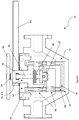
- Disclosed invention proposes a bidirectional check valve (10) capable of flow manipulation and control in opposite directions, also capable of maintaining a desired and steady flow rate in either direction effectively, while retaining the ability to act as a stop valve.
- Valve body (11) that comprises multliple interdependent parts serve as a fluid containment space, wherein two concentric parts, namely a plug (13) and a piston (17), are 7
- Said plug (13) which is essentially a rotating clapper body comprises a fluid corridor of double-layered design, houses a piston (17) which is analogous to a clapper that prevents fluid flow in the opposite direction by its spatial relationship to said plug (13).
- a piston (17) which is analogous to a clapper that prevents fluid flow in the opposite direction by its spatial relationship to said plug (13).
- Disclosed invention also offers the identical effect via rotating the plug (13) with respect to the piston/clapper part, such that its double-layered corridor is perpendicularly positioned with respect to the possible directions of fluid movement.
- said system offers a versatile extension of functionality next to the established solutions in the art which include conventional approaches of stop check valves either acting as a globe valve for isolating or controlling flow rate or a check valve for preventing reverse flow.
- a piping system or configuration utilizes disclosed device; problem of check valves in the art not allowing flow in an opposite direction is solved.
- the same pipe path could be utilized for both directions e.g. filling and emptying a certain container; delivering fluids of different character between different points in the system etc.
- These cases require two different fluid delivery paths (pipelines) to operate on said conditions, or to accomplish similar tasks in the art.
- the 180-degree reversible, flow controlling stop check valve as put forth in the disclosed invention, tasks such as filling and emptying storage units e.g. tanks, silos etc. could be realized on one fluid delivery path; in that, no drastic structural alterations need to be made other than actuation and/or rotation of related parts on the bidirectional stop check valve.
- One of such parts is the flow adjustment means (19) which, along with a pitched element of flow adjustment screw (20) changes the horizontal position of the piston (17) which comprises at least one cavity for fluid to pass through.
- said piston (17) comprises two cavities that crisscross through its body and exit on opposite sides.
- said two cavities are directionwise perpendicularly drilled.
- said bidirectional check valve (10) comprises a valve body (11) that is characterized by two ends connectible to other piping elements of a piping system, and a central portion incrementally doubling in height equivalent to the size of two pipes stacked on top of one another. According to an embodiment, said incremental doubling in height of said central portion of the valve body (11) takes place in a downward slope.
- valve body (11) is closed with a body cap (12) that ensures the confinement of fluid within the space designated by said valve body (11); next to keeping other parts comprised thereby intact.
- Said double chambers found in the plug (13) situated in the valve body (11) under the body cap (12) have opposite openings, i.e. one opening faces one end of said valve body (1) while one other opening faces the other end.
- said plug (13) have an upper portion (13a) and a lower portion (13b) which, when conjoined, make up said double-chambered structure.
- one of said plug (13) openings stay level with the valve body (11) while the opposite opening faces the bottom of the sloped-down central portion of valve body (11).
- said piston (17) is movably positioned in the upper portion (13a) comprising the upper chamber of said plug (13), with a piston spring (18) positioned between the roof of said upper chamber and the top surface of said piston (17).
- said valve body (11) comprises a space for a comfortable and rotatable fit of said plug (13) therewithin. Said space is designated with one sleeve (14) that is sandwiched between one sleeve seal (15) contacting the valve body (11) and one plug seal (16) contacting said plug (13).
- said plug (13) is separated from the valve body (11) via the multiplicity of two plugs and a sleeve; which comprise holes that serve as flow gates (25).
- said flow gates (25) are positioned on the sandwiched seal-sleeve-seal layers in such a way that they coincide perfectly, or at least substantially with the openings of chambers found in said plug (13).
- one reciprocal flow gate (25) pair (e.g. one top, one bottom) will allow fluid to be delivered in and out of the plug (3), and for the opposite flow direction, the same effect will be achieved when said plug (13) is rotated in the other parallel position and the other reciprocal flow gate pair is engaged.
- said sleeve seal (15) facing the valve body (11) is held to said sleeve (14) with an adhesive.
- said plug seal (16) is also held to said sleeve (14) on its respective surface.
- the outside surface of said plug (13) is in contact with the plug seal (16), the opposite surface of which is in contact with the sleeve (14), and as such, is rotatable.
- Said plug therefore rotatably fits inside the space as mentioned above, and extends upwards from the body cap (12) to establish connection with a means to rotate said plug (13).
- Upwards-extending body of said plug (13) is connected to a plug rotation means (21) that, according to one embodiment, is a rod conveniently rotating said plug (13) whenever a suitable magnitude of torque is applied.
- Said plug rotation means (10) could be elongated or shortened for different designs so as to facilitate the rotation process of said plug (13).
- Said plug rotation means (21) is, according to an embodiment, confined to the circumference of the outer protruding portion of said plug (13) extending outwards from the body cap (12).
- said plug (13) is of a two-piece structure, in that it comprises an upper portion (13a) and a lower portion (13b).
- Said lower portion (13b) of said plug (13) houses the lower of the two chambers, whereas said upper portion (13a) of said plug (13) houses the upper of the two chambers.
- Said upper portion also comprises the extension that extends upwards from the body cap (12) as mentioned earlier.
- said lower portion (13b) and upper portion (13a) are joined together once the piston (17) and the piston spring (18) are inserted to the predefined position situated therebetween.
- part of said plug (13) extending outwards from said body cap (12) covering said valve body (11) is tubular and comprises a pitched cavity.
- Said pitched cavity is suitable for inserting a screw for rotating the piston (17) that is found inside the top chamber of the two-chamber structure of said plug (13).
- Screw inserted to said pitched cavity is, according to at least one embodiment, a flow adjustment screw (20), that is connected to the piston (17) on one end and a flow adjustment means (19) on the other end outside the valve body (11).
- said flow adjustment means (19) is a wheel.
- said flow adjustment screw (20) moving the piston (17) in said plug (13) is fixed with a gasket (22) on the remaining outer protruding part of said plug (13), a portion of the cavity of which is not pitched and considerably wider. Space between said wider cavity portion and the body of said flow adjustment screw (20) is accommodated with said gasket (22), on top of which a gasket nut (23) is attached to prevent leakage.
- a mechanism comprising two different independently rotatable structures is formed. Said two different structures as sections of said valve are flow adjustment screw (20) rotatable with the flow adjustment means (19) and the plug (13) of said valve rotatable with the plug rotation means (21).
- a 180-degree controllable bidirectional check valve comprising a valve body (11) with a two-level fluid passageway, housing a rotatable clapper body (13) and a piston (17) drivably positioned within said rotatable clapper body (13) is proposed.
- said rotatable clapper body (13) further comprises a two-chambered cavity to establish connection with opposite ends of said two-level fluid passageway of said valve body (11).
- said piston (17) further comprises at least one cavity whereby fluid delivery between said two levels of the passageway is facilitated or cut off upon vertical actuation of said piston (17).
- said rotatable clapper body (13) comprises an upper portion (13a) and a lower portion (13b).
- said upper portion (13a) and lower portion (13b) further comprise chambers with openings facing opposite directions.
- said rotatable clapper body (13) comprises a cavity between said lower portion (13b) and said upper portion (13a) thereof for said piston (17) to fit comfortably and rotatably therein.
- said upper portion (13a) comprises a piston spring (18) between upper surface of the chamber and top surface of said piston (17), whereby a closed position of said piston is reinforced.
- said bidirectional check valve (10) further comprises a plug rotation means (21) to rotate said rotatable clapper body (13).
- said bidirectional check valve (10) further comprises a flow adjustment means (19) to rotate said piston (17).
Landscapes
- Engineering & Computer Science (AREA)
- General Engineering & Computer Science (AREA)
- Mechanical Engineering (AREA)
- Physics & Mathematics (AREA)
- Fluid Mechanics (AREA)
- Check Valves (AREA)
Priority Applications (2)
| Application Number | Priority Date | Filing Date | Title |
|---|---|---|---|
| EP20160846.0A EP3875813A1 (de) | 2020-03-04 | 2020-03-04 | Um 180 grad steuerbares und umkehrbares durchflussrückschlagventil |
| TR2021/004166A TR2021004166A2 (tr) | 2020-03-04 | 2021-03-03 | A 180-degree controllabe and reversible flow check valve |
Applications Claiming Priority (1)
| Application Number | Priority Date | Filing Date | Title |
|---|---|---|---|
| EP20160846.0A EP3875813A1 (de) | 2020-03-04 | 2020-03-04 | Um 180 grad steuerbares und umkehrbares durchflussrückschlagventil |
Publications (1)
| Publication Number | Publication Date |
|---|---|
| EP3875813A1 true EP3875813A1 (de) | 2021-09-08 |
Family
ID=69770577
Family Applications (1)
| Application Number | Title | Priority Date | Filing Date |
|---|---|---|---|
| EP20160846.0A Withdrawn EP3875813A1 (de) | 2020-03-04 | 2020-03-04 | Um 180 grad steuerbares und umkehrbares durchflussrückschlagventil |
Country Status (2)
| Country | Link |
|---|---|
| EP (1) | EP3875813A1 (de) |
| TR (1) | TR2021004166A2 (de) |
Cited By (1)
| Publication number | Priority date | Publication date | Assignee | Title |
|---|---|---|---|---|
| CN119712886A (zh) * | 2023-09-28 | 2025-03-28 | 中国石油天然气集团有限公司 | 一种顶驱旋塞阀 |
Citations (10)
| Publication number | Priority date | Publication date | Assignee | Title |
|---|---|---|---|---|
| US1005523A (en) * | 1911-04-27 | 1911-10-10 | Harry G Dunlap | Reversible check-valve and cut-off. |
| US1125675A (en) * | 1913-01-21 | 1915-01-19 | William A Elder | Valve. |
| US1577375A (en) * | 1925-03-21 | 1926-03-16 | Harold A Showers | Reversible check valve and stop |
| US2642262A (en) * | 1948-04-26 | 1953-06-16 | Joe M Johnson | Valve |
| US2918083A (en) * | 1954-06-07 | 1959-12-22 | James Pond Clark | Check valve and cage construction |
| US3851665A (en) | 1973-08-09 | 1974-12-03 | D Coughlin | Testable plug shut-off and double check valve |
| US4969484A (en) | 1990-02-07 | 1990-11-13 | Graves John G | Reversible flow check valve |
| US8584705B2 (en) | 2010-04-17 | 2013-11-19 | Richard C Hughes | Bidirectional sleeved/plug ball check valve |
| CN204942605U (zh) * | 2015-07-16 | 2016-01-06 | 浙江中鑫管业有限公司 | 一种可双向转换压差阀 |
| CN107917233A (zh) | 2017-11-17 | 2018-04-17 | 成都市同展食品有限公司 | 一种t形三通道换向及自动止回柱塞阀门 |
-
2020
- 2020-03-04 EP EP20160846.0A patent/EP3875813A1/de not_active Withdrawn
-
2021
- 2021-03-03 TR TR2021/004166A patent/TR2021004166A2/tr unknown
Patent Citations (10)
| Publication number | Priority date | Publication date | Assignee | Title |
|---|---|---|---|---|
| US1005523A (en) * | 1911-04-27 | 1911-10-10 | Harry G Dunlap | Reversible check-valve and cut-off. |
| US1125675A (en) * | 1913-01-21 | 1915-01-19 | William A Elder | Valve. |
| US1577375A (en) * | 1925-03-21 | 1926-03-16 | Harold A Showers | Reversible check valve and stop |
| US2642262A (en) * | 1948-04-26 | 1953-06-16 | Joe M Johnson | Valve |
| US2918083A (en) * | 1954-06-07 | 1959-12-22 | James Pond Clark | Check valve and cage construction |
| US3851665A (en) | 1973-08-09 | 1974-12-03 | D Coughlin | Testable plug shut-off and double check valve |
| US4969484A (en) | 1990-02-07 | 1990-11-13 | Graves John G | Reversible flow check valve |
| US8584705B2 (en) | 2010-04-17 | 2013-11-19 | Richard C Hughes | Bidirectional sleeved/plug ball check valve |
| CN204942605U (zh) * | 2015-07-16 | 2016-01-06 | 浙江中鑫管业有限公司 | 一种可双向转换压差阀 |
| CN107917233A (zh) | 2017-11-17 | 2018-04-17 | 成都市同展食品有限公司 | 一种t形三通道换向及自动止回柱塞阀门 |
Cited By (1)
| Publication number | Priority date | Publication date | Assignee | Title |
|---|---|---|---|---|
| CN119712886A (zh) * | 2023-09-28 | 2025-03-28 | 中国石油天然气集团有限公司 | 一种顶驱旋塞阀 |
Also Published As
| Publication number | Publication date |
|---|---|
| TR2021004166A2 (tr) | 2021-09-21 |
Similar Documents
| Publication | Publication Date | Title |
|---|---|---|
| DE69614699T2 (de) | Vereinfachter christbaum mit unterwasser-testbaum | |
| DE10130956A1 (de) | Durchgangsventil | |
| CN207880120U (zh) | 一种转换球阀 | |
| EP3875813A1 (de) | Um 180 grad steuerbares und umkehrbares durchflussrückschlagventil | |
| DE8810233U1 (de) | Dreiwege-Ventil | |
| DE102004018277A1 (de) | Konstruktion für eine einarmige, nur durch Drehen betätigte Mischbatterie | |
| US4520994A (en) | Sub-surface safety gate valve | |
| US3111299A (en) | Rotary plug valve | |
| EP0060529A1 (de) | Mehrwegeventil mit einem Eingang und mindestens zwei Ausgängen, vorzugsweise Vierwegeventil | |
| US4392631A (en) | Sub-surface safety gate valve | |
| CN207246481U (zh) | 一种三通型套筒调节阀 | |
| CN114922998A (zh) | 多用途内螺纹球阀 | |
| CN210510342U (zh) | 一种液动超高压水液压抗污染阀门 | |
| CN220318658U (zh) | 多栓口湿式消防栓 | |
| RU2005102877A (ru) | Установка для отсекания и регулирования потока в скважине с одним или несколькими пластами | |
| CN105156689A (zh) | 一种新型阀门 | |
| CN108360996B (zh) | 井口旋转换向防喷一体化装置 | |
| CN117072718A (zh) | 一种液压先导控制的两位四通水介质换向球阀 | |
| RU2357141C1 (ru) | Кран двухконтурный | |
| CN207814520U (zh) | 能够灵活更换流通方向的储运用阀门结构 | |
| DE202009015397U1 (de) | Thermische Anschlussdose und diese umfassende Betonkerntemperierung | |
| AT500339B1 (de) | Anschlussarmatur | |
| CN221525583U (zh) | 一种高密封性双导向式消防阀 | |
| KR20200130462A (ko) | 선박용 유체 제어 밸브 장치 | |
| ES2954664T3 (es) | Válvula de pinza rotativa asistida por presión |
Legal Events
| Date | Code | Title | Description |
|---|---|---|---|
| PUAI | Public reference made under article 153(3) epc to a published international application that has entered the european phase |
Free format text: ORIGINAL CODE: 0009012 |
|
| STAA | Information on the status of an ep patent application or granted ep patent |
Free format text: STATUS: THE APPLICATION HAS BEEN PUBLISHED |
|
| AK | Designated contracting states |
Kind code of ref document: A1 Designated state(s): AL AT BE BG CH CY CZ DE DK EE ES FI FR GB GR HR HU IE IS IT LI LT LU LV MC MK MT NL NO PL PT RO RS SE SI SK SM TR |
|
| STAA | Information on the status of an ep patent application or granted ep patent |
Free format text: STATUS: THE APPLICATION IS DEEMED TO BE WITHDRAWN |
|
| 18D | Application deemed to be withdrawn |
Effective date: 20220310 |