EP3875047A1 - Catheter proximal joint - Google Patents
Catheter proximal joint Download PDFInfo
- Publication number
- EP3875047A1 EP3875047A1 EP21160807.0A EP21160807A EP3875047A1 EP 3875047 A1 EP3875047 A1 EP 3875047A1 EP 21160807 A EP21160807 A EP 21160807A EP 3875047 A1 EP3875047 A1 EP 3875047A1
- Authority
- EP
- European Patent Office
- Prior art keywords
- proximal
- catheter
- guidewire
- distal
- proximal joint
- Prior art date
- Legal status (The legal status is an assumption and is not a legal conclusion. Google has not performed a legal analysis and makes no representation as to the accuracy of the status listed.)
- Pending
Links
Images


Classifications
-
- A—HUMAN NECESSITIES
- A61—MEDICAL OR VETERINARY SCIENCE; HYGIENE
- A61B—DIAGNOSIS; SURGERY; IDENTIFICATION
- A61B17/00—Surgical instruments, devices or methods, e.g. tourniquets
- A61B17/22—Implements for squeezing-off ulcers or the like on the inside of inner organs of the body; Implements for scraping-out cavities of body organs, e.g. bones; Calculus removers; Calculus smashing apparatus; Apparatus for removing obstructions in blood vessels, not otherwise provided for
- A61B17/221—Gripping devices in the form of loops or baskets for gripping calculi or similar types of obstructions
-
- A—HUMAN NECESSITIES
- A61—MEDICAL OR VETERINARY SCIENCE; HYGIENE
- A61B—DIAGNOSIS; SURGERY; IDENTIFICATION
- A61B17/00—Surgical instruments, devices or methods, e.g. tourniquets
- A61B17/22—Implements for squeezing-off ulcers or the like on the inside of inner organs of the body; Implements for scraping-out cavities of body organs, e.g. bones; Calculus removers; Calculus smashing apparatus; Apparatus for removing obstructions in blood vessels, not otherwise provided for
-
- A—HUMAN NECESSITIES
- A61—MEDICAL OR VETERINARY SCIENCE; HYGIENE
- A61M—DEVICES FOR INTRODUCING MEDIA INTO, OR ONTO, THE BODY; DEVICES FOR TRANSDUCING BODY MEDIA OR FOR TAKING MEDIA FROM THE BODY; DEVICES FOR PRODUCING OR ENDING SLEEP OR STUPOR
- A61M25/00—Catheters; Hollow probes
- A61M25/0043—Catheters; Hollow probes characterised by structural features
-
- A—HUMAN NECESSITIES
- A61—MEDICAL OR VETERINARY SCIENCE; HYGIENE
- A61M—DEVICES FOR INTRODUCING MEDIA INTO, OR ONTO, THE BODY; DEVICES FOR TRANSDUCING BODY MEDIA OR FOR TAKING MEDIA FROM THE BODY; DEVICES FOR PRODUCING OR ENDING SLEEP OR STUPOR
- A61M25/00—Catheters; Hollow probes
- A61M25/01—Introducing, guiding, advancing, emplacing or holding catheters
- A61M25/09—Guide wires
- A61M25/0905—Guide wires extendable, e.g. mechanisms for extension
-
- A—HUMAN NECESSITIES
- A61—MEDICAL OR VETERINARY SCIENCE; HYGIENE
- A61B—DIAGNOSIS; SURGERY; IDENTIFICATION
- A61B17/00—Surgical instruments, devices or methods, e.g. tourniquets
- A61B2017/00477—Coupling
-
- A—HUMAN NECESSITIES
- A61—MEDICAL OR VETERINARY SCIENCE; HYGIENE
- A61B—DIAGNOSIS; SURGERY; IDENTIFICATION
- A61B17/00—Surgical instruments, devices or methods, e.g. tourniquets
- A61B2017/00831—Material properties
- A61B2017/0084—Material properties low friction
-
- A—HUMAN NECESSITIES
- A61—MEDICAL OR VETERINARY SCIENCE; HYGIENE
- A61B—DIAGNOSIS; SURGERY; IDENTIFICATION
- A61B17/00—Surgical instruments, devices or methods, e.g. tourniquets
- A61B2017/00831—Material properties
- A61B2017/00853—Material properties low friction, hydrophobic and corrosion-resistant fluorocarbon resin coating (ptf, ptfe, polytetrafluoroethylene)
-
- A—HUMAN NECESSITIES
- A61—MEDICAL OR VETERINARY SCIENCE; HYGIENE
- A61B—DIAGNOSIS; SURGERY; IDENTIFICATION
- A61B17/00—Surgical instruments, devices or methods, e.g. tourniquets
- A61B2017/00831—Material properties
- A61B2017/00898—Material properties expandable upon contact with fluid
-
- A—HUMAN NECESSITIES
- A61—MEDICAL OR VETERINARY SCIENCE; HYGIENE
- A61B—DIAGNOSIS; SURGERY; IDENTIFICATION
- A61B17/00—Surgical instruments, devices or methods, e.g. tourniquets
- A61B2017/00831—Material properties
- A61B2017/00955—Material properties thermoplastic
-
- A—HUMAN NECESSITIES
- A61—MEDICAL OR VETERINARY SCIENCE; HYGIENE
- A61B—DIAGNOSIS; SURGERY; IDENTIFICATION
- A61B17/00—Surgical instruments, devices or methods, e.g. tourniquets
- A61B17/22—Implements for squeezing-off ulcers or the like on the inside of inner organs of the body; Implements for scraping-out cavities of body organs, e.g. bones; Calculus removers; Calculus smashing apparatus; Apparatus for removing obstructions in blood vessels, not otherwise provided for
- A61B2017/22001—Angioplasty, e.g. PCTA
-
- A—HUMAN NECESSITIES
- A61—MEDICAL OR VETERINARY SCIENCE; HYGIENE
- A61B—DIAGNOSIS; SURGERY; IDENTIFICATION
- A61B17/00—Surgical instruments, devices or methods, e.g. tourniquets
- A61B17/22—Implements for squeezing-off ulcers or the like on the inside of inner organs of the body; Implements for scraping-out cavities of body organs, e.g. bones; Calculus removers; Calculus smashing apparatus; Apparatus for removing obstructions in blood vessels, not otherwise provided for
- A61B2017/22038—Implements for squeezing-off ulcers or the like on the inside of inner organs of the body; Implements for scraping-out cavities of body organs, e.g. bones; Calculus removers; Calculus smashing apparatus; Apparatus for removing obstructions in blood vessels, not otherwise provided for with a guide wire
- A61B2017/22049—Means for locking the guide wire in the catheter
-
- A—HUMAN NECESSITIES
- A61—MEDICAL OR VETERINARY SCIENCE; HYGIENE
- A61B—DIAGNOSIS; SURGERY; IDENTIFICATION
- A61B17/00—Surgical instruments, devices or methods, e.g. tourniquets
- A61B17/22—Implements for squeezing-off ulcers or the like on the inside of inner organs of the body; Implements for scraping-out cavities of body organs, e.g. bones; Calculus removers; Calculus smashing apparatus; Apparatus for removing obstructions in blood vessels, not otherwise provided for
- A61B2017/22079—Implements for squeezing-off ulcers or the like on the inside of inner organs of the body; Implements for scraping-out cavities of body organs, e.g. bones; Calculus removers; Calculus smashing apparatus; Apparatus for removing obstructions in blood vessels, not otherwise provided for with suction of debris
-
- A—HUMAN NECESSITIES
- A61—MEDICAL OR VETERINARY SCIENCE; HYGIENE
- A61M—DEVICES FOR INTRODUCING MEDIA INTO, OR ONTO, THE BODY; DEVICES FOR TRANSDUCING BODY MEDIA OR FOR TAKING MEDIA FROM THE BODY; DEVICES FOR PRODUCING OR ENDING SLEEP OR STUPOR
- A61M25/00—Catheters; Hollow probes
- A61M25/01—Introducing, guiding, advancing, emplacing or holding catheters
- A61M25/09—Guide wires
- A61M2025/09175—Guide wires having specific characteristics at the distal tip
-
- A—HUMAN NECESSITIES
- A61—MEDICAL OR VETERINARY SCIENCE; HYGIENE
- A61M—DEVICES FOR INTRODUCING MEDIA INTO, OR ONTO, THE BODY; DEVICES FOR TRANSDUCING BODY MEDIA OR FOR TAKING MEDIA FROM THE BODY; DEVICES FOR PRODUCING OR ENDING SLEEP OR STUPOR
- A61M25/00—Catheters; Hollow probes
- A61M25/0067—Catheters; Hollow probes characterised by the distal end, e.g. tips
- A61M25/0068—Static characteristics of the catheter tip, e.g. shape, atraumatic tip, curved tip or tip structure
Definitions
- the present invention generally relates proximal joints for linking a catheter body to a catheter guidewire. More specifically, the present invention relates to joints which provide a gradual stiffness change between the catheter body and guidewire.
- Aspiration and clot retrieval catheters and devices are used in mechanical thrombectomy for endovascular intervention, often in cases where patients are suffering from conditions such as acute ischemic stroke (AIS), myocardial infarction (MI), and pulmonary embolism (PE).
- AIS acute ischemic stroke
- MI myocardial infarction
- PE pulmonary embolism
- Accessing the neurovascular bed in particular is challenging with conventional technology, as the target vessels are small in diameter, remote relative to the site of insertion, and are highly tortuous.
- Traditional devices are often either too large in profile, lack the deliverability and flexibility needed to navigate tortuous vessels, or are not effective at removing a clot when delivered to the target site.
- Solutions such as highly flexible catheter body designs, are often of a reduced diameter incapable of generating the required suction force.
- Improved aspiration designs such as those with expandable members or separate suction extensions, typically lack the flexibility to navigate the neurovascular intact.
- the present design is aimed at providing an improved proximal joint giving better performance characteristics to an aspirating retrieval catheter which addresses the above-stated deficiencies.
- the transition joint can be low-profile and sufficiently flexible in multiple directions for deliverability to the target site, while providing a smooth transition in stiffness between catheter segments.
- the transition joint can include an outer seal that interacts with an outer catheter such that an aspiration source is connected to the proximal end of the outer catheter has a direct fluidic connection to the distal mouth of the aspiration clot retrieval catheter. The seal ensures there is little or no loss in negative pressure between the aspiration source and the mouth.
- the transition can be a proximal joint for linking a catheter with a tubular body and a guidewire for manipulation.
- the proximal joint can have a distal tubular section defining an internal lumen therethrough and a proximal strut extending proximal to the distal tubular section.
- the distal tubular section can include one or more axial spines, a plurality of ribs along the one or more spines and disposed around a longitudinal axis, and a tapered opening.
- the internal lumen of the distal tubular section can be shared with the lumen of the tubular catheter body used for passing devices and directing aspiration.
- the proximal strut can be integral with and extend proximally from one of the one or more spines.
- the strut can be configured to overlap a distal portion of the guidewire to form a zone for mechanically locking the guidewire to the catheter body.
- At least a portion of the distal tubular section can be coated with a flexible and highly elastic polymeric cover which can be stretched to the contours of the tubular section and catheter body.
- the distal tubular section can be formed integrally with the catheter body and help support the outer cover or membrane.
- the structures could be cut from a single hypotube.
- the tubular section could be a braided or coiled structure of sufficient density to support the cover.
- At least a portion of the tubular section of the proximal joint can be of a diameter larger than the diameter of the catheter body and sized to seal with an outer catheter such that aspiration is directed to the distal tip of the aspirating clot retrieval catheter.
- the ribs of the distal tubular section could be cut to this larger diameter, or they could be enlarged through plastic deformation.
- the tubular section could include a longitudinal slot or slots, and/or the ribs could be machined at an acute angle to the longitudinal axis such that they could be heat set to a larger diameter prior to applying the outer polymer cover or jacket.
- the perimeter of the tapered opening could have notches or cutouts to make the region more compliant in bending.
- the guidewire can have a flattened or rounded distal end depending on the desired interface at the proximal joint of the catheter.
- the guidewire can be formed with features that interlock with features of the proximal strut of the catheter tubular support section such that the features form a mechanical constraint between the support structure and the guidewire.
- locking arms could extend laterally away from the central proximal strut and could be configured to engage corresponding notches in the guidewire shaft within the locking zone.
- one or more pins could extend radially from the proximal strut and be configured to engage with thru holes or pockets in the locking zone of the guidewire shaft.
- the pins and pockets could also be divided between the proximal strut and guidewire and spaced for a smooth stiffness transition through the locking zone.
- Heat-shrink, reflowed polymers, and/or adhesives can be used to reinforce the connection between the guidewire and tubular support section.
- the reinforcement can prevent a disengagement of the mechanical lock between the guidewire and catheter body.
- One or more polymer jacket could extend through at least a portion of the locking zone or could extend the entire length of the guidewire.
- the jacket or jackets could be made from a low-friction material and the edges could be tapered to be flush with the proximal strut and guidewire surfaces such that auxiliary devices used in the procedure are not snagged at the interface.
- Multiple jackets of differing stiffnesses could be used at different longitudinal sections of the guidewire and locking zone.
- a proximal joint for connecting a guidewire to a catheter body can include a tubular support structure formed integrally with and proximal to the catheter body and a proximal strut extending proximal to the support structure and configured to mate with a distal portion of the guidewire.
- the tubular support structure can have a maximum radial size larger than a maximum radial size of the catheter body and sized to seal with the inner diameter of an outer delivery catheter.
- the support structure can be fabricated at the maximum radial size or it can be deformed to flare radially outward.
- a separate seal component can be provided with the joint which expands or swells to direct aspiration to the distal tip of the clot retrieval catheter and isolate fluid proximal of the seal component.
- a highly flexible proximal joint can be positioned over a proximal section of the distal luminal catheter body and may include mechanical lock features similar to those disclosed between the guidewire and proximal joint.
- a cover can be disposed around at least part of the support structure and can extend distally to enclose the catheter body.
- the tubular support structure can have one or more axial spines and a series of loop ribs to support the cover and define a hollow internal lumen for the catheter.
- the lumen can be coated with a low-friction liner to facilitate the passage of ancillary devices through the catheter.
- the cover could be reflowed, adhered, and/or stitched to the loop ribs of the support structure.
- the cover could further be coated with a low-friction film to improve trackability and mitigate the risk of binding when delivered through an outer catheter.
- the proximal strut can be aligned with one of the one or more axial spines extending longitudinally down the support structure.
- the proximal strut can have locking arms that can extend laterally from the strut and bend to engage with notches machined into the distal end of a flattened guidewire.
- the proximal strut can have a concave face for receiving a guidewire with a rounded cylindrical distal end.
- a reinforcing polymer sleeve can be disposed around at least a length of the proximal strut and a length of the guidewire to bolster the joint and dampen the stiffness transition between the guidewire and support structure as well as provide a smooth profile for unhindered passage of ancillary devices.
- a clot retrieval catheter for capturing an occlusive thrombus can have a tubular suction section, a guidewire, and a proximal joint for securing the tubular suction section to the guidewire.
- the proximal joint of the catheter can include a distal tubular structure, a proximal strut extending in a proximal direction from the tubular structure, and a polymeric jacket bonding and securing a length of the proximal strut to a length of the guidewire.
- the proximal strut can be formed integrally with the distal tubular structure such that there is no abrupt stuffiness change or geometric stress concentration.
- the proximal joint can include features configured for mechanically securing the proximal strut and a distal portion of the guidewire, or the polymer jacket can be used to fix the position of and bond overlapped sections of the proximal strut and guidewire. This bond can allow thrust and torque applied to the guidewire by the user to be transmitted to the distal tubular section of the proximal joint and the distal luminal portion of the catheter body.
- the jacket can be applied over just the overlapping portion of the proximal strut and guidewire or could continue proximally a further length of the guidewire.
- a low-friction coating can be applied to the jacket and/or guidewire, or lubricious particles can be impregnated within the jacket for easier navigation within an outer catheter.
- the distal tubular structure can include a tapered opening at the proximal end, one or more axial spines along the longitudinal axis.
- a plurality of loop ribs can extend around the longitudinal axis from the one or more spines and define a hollow inner lumen for the distal tubular structure.
- the distal tubular structure and the catheter body tubular section can be formed integrally, such as when machined from a hypotube or with one or a series of cylindrical braids, such that the hollow inner lumen can be shared between the segments. When constructed in this fashion the magnitude of the stiffness transition between the distal tubular structure and the catheter body tubular section can be mitigated.
- the distal tubular structure can be formed with features that allow some or all of the structure to be enlarged through permanent plastic deformation or a heat set. These features allow the enlarged region to have a greater diameter than the distal tubular catheter body.
- An enlarged region can expedite the passage of thrombectomy devices and/or can form a seal with an outer delivery catheter for the efficient direction of suction to the distal tip of the clot retrieval catheter. This sealed configuration takes advantage of the large proximal lumen of the outer catheter to enhance aspiration through the clot retrieval catheter.
- an enlarged section could be formed from one or more longitudinal slots incorporated into the distal tubular structure such that the ribs adjacent to the slot are not constrained tangentially so they can be deformed, or heat set to a larger radial size.
- the ribs of the distal tubular section could be formed or machined from a shape memory alloy at an angle less than 90 degrees to the longitudinal axis. These ribs could subsequently be heat set to an angle largely perpendicular to the longitudinal axis to achieve an enlarged section of the distal tubular structure.
- the distal tubular section could effectively be enlarged through a hydrogel coating which swells in an isotropic fashion with hydration to achieve a seal with the outer delivery catheter.
- a flow restrictor can be used between the outer catheter and the clot retrieval catheter.
- the flow restrictor could have bristles, a dense framework, or some other form which could inhibit flow.
- the flow restrictor can be located on the outer surface of the distal tubular structure of the clot retrieval catheter.
- the clot retrieval catheter can further have an expanding distal tip which can provide a larger opening into which a clot retrieval device and a captured thrombus can be withdrawn, lessening the risk of the tip shearing or dislodging the thrombus or fragments of the thrombus from the retrieval device and also providing a gradual compression of clot as the clot is drawn into the mouth of the clot retrieval catheter through aspiration, use of a retrieval device, or through a combination of aspiration and use of a retrieval device. Fragmentation can occur with catheters having a distal mouth with a cross-section smaller than that of the thrombus itself or if the clot enters the mouth of the catheter at an offset position.
- a proximal j oint 100 for connecting a body and a guidewire of an aspirating clot retrieval catheter according to this invention.
- the proximal joint can have a distal tubular section 210 which can include a plurality of loop ribs 216 disposed along one or more axial spines 220 and defining a longitudinal axis 111.
- the distal tubular section can taper proximally to form a tapered opening 212 which can serve as an entrance through which other treatment devices, such as a microcatheter and stentriever, can access the lumen 218 of the tubular section.
- the axially tapering profile of the opening relative to the longitudinal axis can help to facilitate the introduction of these devices to the intralumenal section of the catheter.
- an opening at a right angle can be used if desired.
- the opening 212 can have notches or breaks 214 cut into the perimeter to reduce the bending stiffness of the opening as it transitions to one of the spines 220 to a tubular profile.
- distal tubular section tubular support structure, and distal tubular structure as used herein are intended to refer to the same structure and are used interchangeably. It can be appreciated that other appropriate verbiage could also be substituted.
- the proximal joint 100 can have an axial member which extends proximally from the distal tubular section 210 where the tapered opening 212 transitions away from the suction body of the catheter.
- the member can be a proximal strut 110 designed to provide an interface with which to link a pushable guidewire 30 to the catheter.
- the strut member can be a cylindrical or rectangular strut which can form a continuous extension from one of the spines 220 of the distal tubular section.
- the strut can be a flat wire or coil which is embedded into a polymeric anchor of the distal tubular section.
- the wall of the tubular section could be formed with a thicker section along one edge of the circumference to serve as the anchor and reinforce the interface.
- the loop ribs 216 and the one or more axial spines 220 of the distal tubular section 210 could be formed from laser-cutting a hypotube or similar tube stock. Commonly used hypotube materials include Nitinol and familiar medical-grade stainless-steel alloys like 304 and 316.
- the distal tubular section is formed integrally with the proximal strut 110 and the tubular luminal body of the catheter. This configuration allows for one of the one or more spines 220 to continue proximal of the tapered opening 212 as a continuous proximal strut 110 member. A continuous spine and proximal strut combination could yield excellent pushability characteristics while maintaining a gentler bending stiffness transition between the proximal strut and the distal tubular section.
- Tailoring of the stiffness and changes in stiffness for the catheter is important for situations where the distances and tortuosity can be significant, such as when it must be advanced from a patient's inner thigh, over the cardiac arch, and up into the neurovascular vessels inside the skull.
- Adjusting the cuts in a hypotube which form the ribs 216 and spines 210 of the distal tubular section 210 can be used to tailor this stiffness.
- the ribs can be cut to various widths and spacing density.
- the cuts could be circumferentially continuous and terminate on either side of an axial spine 220, or the cuts could be discontinuous in a repeating or non-repeating pattern around the circumference of the tubular section.
- discontinuous cuts are aligned axially, they can form one or more additional axial spines 220 to bias bending and flexing planes of the catheter.
- circumferentially discontinuous cuts are mixed and aligned with circumferentially continuous cuts, as shown in Fig. 1 , they can form a discontinuous axial spine.
- the axial spine or spines 210 themselves could be formed or cut at various thicknesses.
- a thicker spine could provide more column strength and axial stiffness for better kink resistance and insertion and retraction performance of the catheter.
- a spine of a thinner thickness could provide more flexibility in bending for navigating tortuous areas of the vasculature.
- the spine or spines could also taper in thickness along the length of its axis in order to incorporate both of these advantages.
- a tapered spine or spines could be made stiffer proximally for good pushability characteristics and very flexible distally to allow the tubular section to contort and twist around the vessel paths.
- the distal tubular section 210 of the proximal joint 100 can have a metal and/or polymer strand construction formed into a braided or coiled structure.
- the strands can form a radial array as a continuous structure with the tubular catheter body in order to approximate a singular support piece, similar to that of a laser-cut hypotube.
- the strands of the distal tubular section can be formed on a straight mandrel so that they flare radially outward to form a seal with the inner diameter of an outer or intermediate catheter. Instead of a seal, the strands form a braided or coiled structure of sufficient density that fluid flow is substantially impeded between the exterior and interior of the tubular section, such that a perfect seal is not necessary.
- the proximal strut 110 can be formed with features that grip features of the catheter guidewire 30 such that the features form a mechanical lock between the support structure and the guidewire.
- the features can be chosen such that they prevent axial translation but do not inhibit the joint from bending or twisting about the longitudinal axis 111.
- lateral material extensions can flank the proximal strut to form locking arms 114.
- the locking arms can be laser-cut such that they are integral with the proximal strut and radially perpendicular to the axis as shown in Fig. 2A .
- the locking arms When the proximal joint is assembled, the locking arms can be heat set or plastically deformed to a position radially inward in order to engage with complimentary notches 32 or slots machined into the surfaces near the distal end 36 of the guidewire 30, as illustrated in Fig. 2B .
- the guidewire 30 itself can have any of a number of reasonable cross-sectional profiles which can be different for different axial lengths of the guidewire.
- the guidewire can taper to a smaller profile or circumference at the distal end 36 of the guidewire, such that when joined with the proximal strut 110 or mating member of the proximal joint the sections share a composite stiffness more approximate that of wider proximal sections of the guidewire.
- the guidewire 30 can be a solid wire, braid, coil, or the like that provides for the smooth transmission of thrust and retraction forces to the tubular section 210 of the proximal joint 100 of the catheter, allowing the catheter to move with the tubular section relative to an outer catheter (not illustrated) in the assembled clot retrieval system.
- the guidewire can have a length longer than that of an outer catheter so that the proximal end of the guidewire extends from the proximal end of the outer catheter.
- the guidewire can be constructed of a high-modulus polymer, or any of a range of biocompatible metallic options such as titanium, Nitinol, or stainless-steel alloys as long as they have sufficient proportions of flexibility and column stiffness necessary to navigate requisite areas of the vasculature.
- proximal strut 110 of the proximal joint 100 and the portion of the guidewire 30 approximate the guidewire distal end 36 both resemble cantilever beams.
- a section of the guidewire can overlap longitudinally with a section of the proximal strut as illustrated in Fig. 3 . This overlap can define a locking zone 116 designating an engagement length over which the joint becomes a composite beam.
- the locking arms 114 or other geometric features of the proximal strut can then engage to secure the interface.
- the guidewire utilizes cylindrical locking pins 120 extending radially within the locking zone 116 near the distal end 36 of the guidewire 30.
- the locking pins can be configured for insertion into corresponding locking pockets 122 recessed into the proximal strut 110.
- the joint could be made more secure by having the locking pins and locking pockets interface as a snap fit or interference fit.
- the pins could be machined as extensions of the proximal strut. Rounded pins can reduce the stress concentrations inherent at geometric corners and provide a proximal joint interface with additional torque carrying capacity.
- proximal joint locking systems shown and described herein are a small number of available designs, and one of skill in the art will recognize that many other configurations are possible beyond what is explicitly described.
- Fig. 5A shows an example of a proximal joint where a polymer jacket 118 has been heat-shrunk or reflowed over the length of the locking zone 116 to reinforce the mechanical joint between the proximal strut 110 and the catheter guidewire 30.
- the polymer jacket can further blend the geometric transition at the proximal and distal ends of the locking zone 116.
- the jacket can extend proximally along the guidewire beyond the edge of the locking zone and distally to the very proximal face of the enlarged tapered opening of the tubular section to completely bond and reinforce the joint assembly. As illustrated in Fig.
- the edges of the jacket 118 can be made flush with the corresponding surfaces of guidewire and proximal strut so that there are no lips or corners of the locking zone interface or jacket which could otherwise snag or inhibit ancillary devices as they are delivered through the clot retrieval catheter.
- the guidewire 30 or the proximal strut 110 could be shaped to fit inside a hollow housing of the opposite number and a press-fit or adhering element used to secure the mating surfaces.
- a polymer jacket 118 could then be reflowed over the locking zone 116 to form a more continuous external profile.
- adhesives could also be used with or without polymer jackets to constrain and/or fortify the proximal joint between the catheter
- the interface of the guidewire 30 with the proximal strut 110 of the proximal joint 100 can serve the purpose of both securing the components together while also developing into the shape of the tapered opening 212 of the distal tubular section 210. Similar to other examples, the tapered opening 212 can have notches or breaks 214 machined into the perimeter to reduce the bending stiffness at the opening.
- the exterior of the tubular section can be sized to form a desired interface between the aspirating clot retrieval catheter and an outer or intermediate catheter.
- the tubular section can form a seal with the inner surface of the outer catheter, such that an aspiration source connected to the proximal end of the outer catheter has a direct connection to the distal mouth of the aspirating clot retrieval catheter with little or no negative pressure loss between the source and the mouth.
- a proximal joint 100 for an aspirating clot retrieval catheter that is capable of sealing with an outer catheter is shown in Figs. 6a .
- the distal tubular section 210 of the proximal joint can still be formed integrally with the tubular catheter body 40, such as when both are cut from the same hypotube or formed from a continuous coiled structure.
- the proximal strut can also be cut as a continuous extension of one of the catheter spines 220.
- the catheter body can have multiple designs, or be cut in different sections, to control the stiffness profile along the length of the body to minimize insertion and retraction forces of the catheter.
- Features can also be incorporated which bias bending about certain planes or encourage twisting to reduce the imparted strains. In this way the catheter will maintain excellent lateral flexibility but will not tend to expand or kink in compression.
- FIG. 6B A cross-sectional view from Fig. 6A through a part of the tubular section of the catheter is illustrated in Fig. 6B .
- the distal tubular section 210 can generally be distinguishable from the catheter body 40 by having an outer diameter 224 larger than the outer diameter 222 of the catheter body extending downstream along the catheter spine or spines 220.
- example illustrated in Fig. 6A has two axial spines spaced 180 degrees apart.
- Use of a double spine yields good thrust and trackability characteristics to aid in advancing the catheter to the target location, while reducing the possibility of elongation under tensile loads, such as when a large clot is retracted into the mouth of an expandable tip at the distal end of the catheter or an outer catheter.
- Fig. 6B Spacing the spines 180 degrees apart also biases the catheter body and tubular section to flex about a single plane in order to transmit a more balanced push force to the catheter.
- the created bending plane passes through the spines of the dual spine layout of Fig. 6B .
- the stepped profile of a spine at the transition between the catheter body 40 and the enlarged outer diameter of the proximal joint tubular section 210 is illustrated in cross-section in Fig. 6C .
- Fig. 7A illustrates a further example of a proximal joint 100 formed integrally with the tubular catheter body 40 where both structures are cut from the same hypotube.
- the adjacent catheter body 40 can have a stepped down diameter from that of the tubular section 210 of the proximal joint.
- the enlarged tubular section can be formed in multiple ways.
- the loop ribs 216 of the tubular section can be machined at an angle less than 90 degrees to the longitudinal axis so that the ribs can be heat set to an angle approximately perpendicular to the axis to achieve the enlarged section 210 proximal to the catheter body 40.
- the machined pattern of the tubular section 210 can include one or more longitudinal slots 226 so that the ribs are not constrained tangentially around the circumference. The ribs can then be reset or deformed to a position radially outward of the more distal portion of the catheter body to achieve an enlarged diameter.
- the longitudinal slot or slots 226 could be machined such that they are aligned with or offset from any of the one or more axial spines 220. If aligned, one or more of the spines could be discontinuous at the transition interface between the enlarged tubular section 210 and the catheter body 40, as seen in the top view of Fig. 7A and in Fig. 7B .
- a discontinuous spine can help the catheter proximal joint further transition the bending stiffness between the downstream catheter body and the connection between proximal strut 110 and the catheter guidewire.
- the distal tubular section 210 can taper gradually inward from the maximum radial size 224 to assume the outer diameter 222 of the catheter body 40.
- the catheter body in these examples can be balanced to transmit a substantial suction force while being capable of further reach into more distant and narrow neurological vessels.
- the diameter 222 of the catheter body shown in Fig. 7A and 7B could also be an intermediate diameter, where the catheter body is formed from further tubular sections which step down to a progressively smaller size, giving enhanced bending flexibility to distal regions of the body.
- the distal end of the catheter body could have an expandable member to recover a large distal mouth for aspirating a clot.
- the interface between the outer diameter of the enlarged tubular section 210 of the proximal joint 100 and the inner diameter of a section of the outer catheter 50 can be seen in Fig. 8 .
- this junction can reduce or eliminate any flow between the surfaces so that essentially all of the suction flow passes through the shared lumen 218 of the tubular section and catheter body 40 to the distal tip of the clot retrieval catheter.
- the enlarged tubular section can be positioned by the user at a desired axial location of the outer catheter such that an adequate seal and functionality are obtained.
- a seal 52 between the proximal joint 100 and the outer catheter 50 can be created in several ways.
- the distal tubular section 210 can be enlarged to extend radially outward to generate a circumferential sealing surface with the inner wall of the outer catheter 50.
- the ribs or the tubular section 210 can be cut or heat set to a larger diameter prior to applying an outer polymer jacket. Slots or strain relief features machined into the cut pattern of the tubular section can also be used to create a geometry that will deform or be effectively spring-loaded to a larger outer diameter.
- the outer jacket or membrane could be formed with a soft elastomeric rib disposed around the tubular section 210. The maximum radial dimensions can thus be designed to interface with commonly sized commercial outer catheters such that a seal is developed at the contact surface.
- a portion of the tubular portion 210 of the proximal joint 100 can be enlarged through coating with a hydrogel that swells with hydration in order to achieve a seal with the inner surface of the outer catheter 50.
- Hydrogels offer the advantages of biocompatibility, relative tackiness as an adhesive, and flexibility enough to accommodate comparative motion of the joint while maintaining molecular stability when swelled.
- the shape and profile of the overlap and the contact surface developed within the locking zone 116 of the proximal joint 100 can be tailored for both the guidewire 30 and the proximal strut 110 to eliminate stiff transitions inherent with assembly of multiple parts. Components which overlap can form weak transitions which are prone to buckling or kinking when butted together. A smoother contact profile between mating parts is typically desirable, so in the illustrated example of Fig. 9A the guidewire transitions from a cylindrical profile to a flattened wire profile near the distal end 36 in order align with the proximal strut extending from a spine 220 of the laser-cut of tubular support section 210.
- the catheter guidewire within the locking zone can maintain the substantially cylindrical structure of Fig. 9B up to the distal end 36.
- the corresponding mating surface of the proximal strut within the locking zone can have a face which forms an extended concave arc with a matching radius of curvature.
- the axial length of the locking zone 116 and the type of mechanical locking joint used will also determine the final bending stiffness properties of the proximal joint. It can be appreciated that longer locking zones allow more material to carry the bending load and thus a more gradual change in stiffness while reducing the bend radius capacity of the joint.
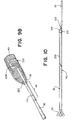
- FIG. 10 A construction view for a suitable aspirating clot retrieval catheter 35 for thrombectomy procedures with aspects of the current design is illustrated in Fig. 10 .
- the catheter can comprise an expandable tip 42 with a collapsed delivery configuration and expanded deployed configuration at the distal end.
- the tip can seal with the walls of an occluded vessel when expanded to direct efficient aspiration.
- a proximal joint 100 with a tubular section 210 can transition an elongate suction catheter body 40 to a guidewire 30 serving as a control element for the catheter.
- the overall length of the guidewire 30 can be substantially greater than the length of the tubular catheter body 40 such that the column strength of the guidewire offers excellent pushability characteristics over the majority of the insertion length.
- the proximal joint 100 manages the transition between these lengths to mitigate the likelihood of binding or kinking at this interface in the complex anatomy of the neurovascular.
- An outer liner or cover 228 can be disposed around at least a portion of the expandable tip 42, catheter body 40, and the tubular section 210 of the proximal joint 100.
- the cover can be a membrane constructed of a highly elastic material, such as a low-modulus elastomer, so that it stretches as the tip expands and can follow the contours of the underlying framework of the catheter.
- the cover can run the entire length of the catheter body and tubular section or it can terminate at or some distance distal to the tapered opening 212.
- the exact composition and structure of the cover 228 can be configured depending on the needs of the procedure.
- the cover can be used for creating the seal with an outer catheter, or it can be used to provide a lubricious surface for limiting the transmission forces needed to deliver and deploy the catheter 35.
- the cover could also be used to adjust the desired stiffness qualities of differing axial portions of the catheter.
- the support framework of the catheter body 40 and tubular section 210 is cut from a hypotube, spaces, slots, or patterns can be laser-cut into the outer surface of the hypotube and the cover 228 could be reflowed or injection molded into the spaces during manufacturing.
- the cover could be adhered to the struts and ribs using heat and/or adhesive.
- the spines and ribs of the support structure could also be embedded or encapsulated in a polymeric tube.
- the tube could be embedded with reinforcing metallic elements or particles with low-friction characteristics to reduce the static and dynamic coefficients of friction for the outer surfaces.
- a low-friction liner such as a fluoropolymer, can also extend through the lumen 218 around the inner diameter of the tubular section 210 and the connecting section of the catheter body 40 to facilitate the feeding of other devices through the aspirating clot retrieval catheter.
- the cover 228 could also be a formed from a series of polymer jackets. Different jackets or sets of jackets could be configured in an axial series to transition the overall stiffness of the catheter from being stiffer at the proximal end to extremely flexible at the distal end. Alternately, the polymer jackets of the cover could be radially disposed about the support tube in order to tailor the material properties through the thickness.
- the expandable tip 42 could have the same or a separate jacket or jackets that can be dip coated and can butt against or extend to be situated under or over the jackets of the support tube.
- Fig. 11A and Fig. 11B show top and side views of the proximal joint 100 from the catheter 35 of Fig. 10 .
- the polymeric membrane cover 228 can be disposed around the distal catheter body 40, but the cover can also enclose all, some, or none of the tubular section 210 of the proximal joint 100. If the membrane is to enclose only a part of the tubular section, the membrane proximal edge could cease just distal of the tapered opening 212.
- the membrane could be reflowed into place as a sleeve, or alternately a dip coating procedure could be used to form the cover.
- a dip coat could cease just distal of the tapered opening for ease of manufacture, thereby covering only the cylindrical section of the tubular section.
- the entire proximal joint could be dip coated and the tapered opening trimmed from the resulting membrane.
- the properties of the membrane could be tuned by adjusting the controlled immersion factors of the dip coating process. For instance, where the membrane is not needed as part of a seal with the outer catheter, the cover can end distal of the tubular section 210 and does not stretch to the increased maximum radial size 224 of the tubular section.
- the reinforcing polymer jacket 118 buttressing the proximal joint 100 in the locking zone 116 can extend the full length of the catheter guidewire 30.
- a longer jacket could further distribute the stiffness changes in the locking zone over a more substantial length.
- the jacket Similar to the cover 228 on the distal tubular section 210 of the catheter and catheter body 40, the jacket could also comprise a series of jackets having different moduli or thicknesses.
- the therapy for retrieving an occlusion using aspiration alone is not possible.
- the lumen 218 of the aspirating clot retrieval catheter can serve as a conduit for delivering a microcatheter and a thrombectomy clot retrieval device to a target occlusion.
- the clot retrieval device can be any of a number of commercially available products, many of which share similar common features.
- the expanded radial size 224 of the tubular section 210 of the proximal joint 100 still provides a seal with an outer catheter so that a suction source, such as a syringe or pump, can be applied to the outer catheter and transferred through to the tip of the clot retrieval catheter.
- a suction source such as a syringe or pump
- the protective seal prevents the distal migration of any liberated clot debris from the thrombectomy procedure while also focusing the aspiration suction distally and restricting fluid proximal of the tip from being drawn into the catheter.
- distal and proximal are used throughout the preceding description and are meant to refer to a positions and directions relative to a treating physician. As such, “distal” or distally” refer to a position distant to or a direction away from the physician. Similarly, “proximal” or “proximally” refer to a position near to or a direction towards the physician. Furthermore, the singular forms “a,” “an,” and “the” include plural referents unless the context clearly dictates otherwise.
Abstract
Description
- The present invention generally relates proximal joints for linking a catheter body to a catheter guidewire. More specifically, the present invention relates to joints which provide a gradual stiffness change between the catheter body and guidewire.
- Aspiration and clot retrieval catheters and devices are used in mechanical thrombectomy for endovascular intervention, often in cases where patients are suffering from conditions such as acute ischemic stroke (AIS), myocardial infarction (MI), and pulmonary embolism (PE). Accessing the neurovascular bed in particular is challenging with conventional technology, as the target vessels are small in diameter, remote relative to the site of insertion, and are highly tortuous. Traditional devices are often either too large in profile, lack the deliverability and flexibility needed to navigate tortuous vessels, or are not effective at removing a clot when delivered to the target site.
- In delivering effective devices to the small and highly branched cerebral artery system, conventional catheters must try and balance a number of factors. The catheter must be sufficiently flexible to navigate the vasculature and endure high flexure strains, while also having the axial stiffness to offer smooth and consistent advancement along the route. Newer designs have been introduced which utilize various methods to alter the stiffness between the proximal and distal portions of the catheter. But abrupt stiffness or geometric changes can hinder trackability, introduce significant stress concentrations, and increase the likelihood of device kinking or buckling. This is especially true in regions where different portions of a catheter are manufactured separately and need to be joined securely by mechanical means. Such instances include when a guidewire or shaft for manipulability is connected to the tubular passageway of the catheter by a proximal joint.
- Other designs for aspirating clot retrieval catheters have difficulty directing the full suction of aspiration to the volume of fluid and clot distal to the mouth. The suction must be strong enough such that any fragmentation that may occur as a result of aspiration or the use of a mechanical thrombectomy device can be held stationary so that fragments cannot migrate and occlude distal vessels. However, when aspirating with traditional catheters, such as a fixed-mouth catheter or a catheter which does not seal with an outer catheter, a significant portion of the aspiration flow ends up coming from vessel fluid proximal to the tip of the catheter, where there is no clot. This significantly reduces aspiration efficiency, lowering the success rate of clot removal.
- Solutions, such as highly flexible catheter body designs, are often of a reduced diameter incapable of generating the required suction force. Improved aspiration designs, such as those with expandable members or separate suction extensions, typically lack the flexibility to navigate the neurovascular intact.
- The present design is aimed at providing an improved proximal joint giving better performance characteristics to an aspirating retrieval catheter which addresses the above-stated deficiencies.
- It is an object of the present design to provide systems, devices, and methods to meet the above-stated needs. It is therefore desirable for an aspiration clot retrieval catheter with a proximal joint for transitioning from a profiled guidewire to a tubular support structure with a large lumen for aspiration and the passing of other devices for performing mechanical thrombectomy procedures. The transition joint can be low-profile and sufficiently flexible in multiple directions for deliverability to the target site, while providing a smooth transition in stiffness between catheter segments. The transition joint can include an outer seal that interacts with an outer catheter such that an aspiration source is connected to the proximal end of the outer catheter has a direct fluidic connection to the distal mouth of the aspiration clot retrieval catheter. The seal ensures there is little or no loss in negative pressure between the aspiration source and the mouth.
- The transition can be a proximal joint for linking a catheter with a tubular body and a guidewire for manipulation. The proximal joint can have a distal tubular section defining an internal lumen therethrough and a proximal strut extending proximal to the distal tubular section. The distal tubular section can include one or more axial spines, a plurality of ribs along the one or more spines and disposed around a longitudinal axis, and a tapered opening. The internal lumen of the distal tubular section can be shared with the lumen of the tubular catheter body used for passing devices and directing aspiration. The proximal strut can be integral with and extend proximally from one of the one or more spines. The strut can be configured to overlap a distal portion of the guidewire to form a zone for mechanically locking the guidewire to the catheter body. At least a portion of the distal tubular section can be coated with a flexible and highly elastic polymeric cover which can be stretched to the contours of the tubular section and catheter body.
- The distal tubular section can be formed integrally with the catheter body and help support the outer cover or membrane. For example, the structures could be cut from a single hypotube. Alternately, the tubular section could be a braided or coiled structure of sufficient density to support the cover. At least a portion of the tubular section of the proximal joint can be of a diameter larger than the diameter of the catheter body and sized to seal with an outer catheter such that aspiration is directed to the distal tip of the aspirating clot retrieval catheter. The ribs of the distal tubular section could be cut to this larger diameter, or they could be enlarged through plastic deformation. If constructed of a shape memory alloy, the tubular section could include a longitudinal slot or slots, and/or the ribs could be machined at an acute angle to the longitudinal axis such that they could be heat set to a larger diameter prior to applying the outer polymer cover or jacket. To further increase the flexibility of the tubular section, the perimeter of the tapered opening could have notches or cutouts to make the region more compliant in bending.
- The guidewire can have a flattened or rounded distal end depending on the desired interface at the proximal joint of the catheter. The guidewire can be formed with features that interlock with features of the proximal strut of the catheter tubular support section such that the features form a mechanical constraint between the support structure and the guidewire. For example, locking arms could extend laterally away from the central proximal strut and could be configured to engage corresponding notches in the guidewire shaft within the locking zone. In another example, one or more pins could extend radially from the proximal strut and be configured to engage with thru holes or pockets in the locking zone of the guidewire shaft. The pins and pockets could also be divided between the proximal strut and guidewire and spaced for a smooth stiffness transition through the locking zone. These features deliver thrust from the user while preventing longitudinal translation between the guidewire and the proximal strut.
- Heat-shrink, reflowed polymers, and/or adhesives can be used to reinforce the connection between the guidewire and tubular support section. The reinforcement can prevent a disengagement of the mechanical lock between the guidewire and catheter body. One or more polymer jacket could extend through at least a portion of the locking zone or could extend the entire length of the guidewire. The jacket or jackets could be made from a low-friction material and the edges could be tapered to be flush with the proximal strut and guidewire surfaces such that auxiliary devices used in the procedure are not snagged at the interface. Multiple jackets of differing stiffnesses could be used at different longitudinal sections of the guidewire and locking zone.
- In another example, a proximal joint for connecting a guidewire to a catheter body can include a tubular support structure formed integrally with and proximal to the catheter body and a proximal strut extending proximal to the support structure and configured to mate with a distal portion of the guidewire. The tubular support structure can have a maximum radial size larger than a maximum radial size of the catheter body and sized to seal with the inner diameter of an outer delivery catheter. The support structure can be fabricated at the maximum radial size or it can be deformed to flare radially outward. Alternatively, a separate seal component can be provided with the joint which expands or swells to direct aspiration to the distal tip of the clot retrieval catheter and isolate fluid proximal of the seal component. In another embodiment, a highly flexible proximal joint can be positioned over a proximal section of the distal luminal catheter body and may include mechanical lock features similar to those disclosed between the guidewire and proximal joint. By mating a highly flexible section of the tubular section of the proximal joint with a highly flexible proximal section of the distal luminal catheter body, impact to the overall stiffness can be minimized.
- A cover can be disposed around at least part of the support structure and can extend distally to enclose the catheter body. The tubular support structure can have one or more axial spines and a series of loop ribs to support the cover and define a hollow internal lumen for the catheter. The lumen can be coated with a low-friction liner to facilitate the passage of ancillary devices through the catheter. The cover could be reflowed, adhered, and/or stitched to the loop ribs of the support structure. The cover could further be coated with a low-friction film to improve trackability and mitigate the risk of binding when delivered through an outer catheter.
- The proximal strut can be aligned with one of the one or more axial spines extending longitudinally down the support structure. The proximal strut can have locking arms that can extend laterally from the strut and bend to engage with notches machined into the distal end of a flattened guidewire. In another example, the proximal strut can have a concave face for receiving a guidewire with a rounded cylindrical distal end. A reinforcing polymer sleeve can be disposed around at least a length of the proximal strut and a length of the guidewire to bolster the joint and dampen the stiffness transition between the guidewire and support structure as well as provide a smooth profile for unhindered passage of ancillary devices.
- Additionally, a clot retrieval catheter for capturing an occlusive thrombus can have a tubular suction section, a guidewire, and a proximal joint for securing the tubular suction section to the guidewire. The proximal joint of the catheter can include a distal tubular structure, a proximal strut extending in a proximal direction from the tubular structure, and a polymeric jacket bonding and securing a length of the proximal strut to a length of the guidewire. The proximal strut can be formed integrally with the distal tubular structure such that there is no abrupt stuffiness change or geometric stress concentration. The proximal joint can include features configured for mechanically securing the proximal strut and a distal portion of the guidewire, or the polymer jacket can be used to fix the position of and bond overlapped sections of the proximal strut and guidewire. This bond can allow thrust and torque applied to the guidewire by the user to be transmitted to the distal tubular section of the proximal joint and the distal luminal portion of the catheter body.
- Where a polymer jacket is used, the jacket can be applied over just the overlapping portion of the proximal strut and guidewire or could continue proximally a further length of the guidewire. A low-friction coating can be applied to the jacket and/or guidewire, or lubricious particles can be impregnated within the jacket for easier navigation within an outer catheter.
- The distal tubular structure can include a tapered opening at the proximal end, one or more axial spines along the longitudinal axis. A plurality of loop ribs can extend around the longitudinal axis from the one or more spines and define a hollow inner lumen for the distal tubular structure. The distal tubular structure and the catheter body tubular section can be formed integrally, such as when machined from a hypotube or with one or a series of cylindrical braids, such that the hollow inner lumen can be shared between the segments. When constructed in this fashion the magnitude of the stiffness transition between the distal tubular structure and the catheter body tubular section can be mitigated.
- The distal tubular structure can be formed with features that allow some or all of the structure to be enlarged through permanent plastic deformation or a heat set. These features allow the enlarged region to have a greater diameter than the distal tubular catheter body. An enlarged region can expedite the passage of thrombectomy devices and/or can form a seal with an outer delivery catheter for the efficient direction of suction to the distal tip of the clot retrieval catheter. This sealed configuration takes advantage of the large proximal lumen of the outer catheter to enhance aspiration through the clot retrieval catheter.
- For example, an enlarged section could be formed from one or more longitudinal slots incorporated into the distal tubular structure such that the ribs adjacent to the slot are not constrained tangentially so they can be deformed, or heat set to a larger radial size. As an alternative, the ribs of the distal tubular section could be formed or machined from a shape memory alloy at an angle less than 90 degrees to the longitudinal axis. These ribs could subsequently be heat set to an angle largely perpendicular to the longitudinal axis to achieve an enlarged section of the distal tubular structure. In a further example, the distal tubular section could effectively be enlarged through a hydrogel coating which swells in an isotropic fashion with hydration to achieve a seal with the outer delivery catheter.
- If a complete seal is not desired, a flow restrictor can be used between the outer catheter and the clot retrieval catheter. The flow restrictor could have bristles, a dense framework, or some other form which could inhibit flow. The flow restrictor can be located on the outer surface of the distal tubular structure of the clot retrieval catheter.
- The clot retrieval catheter can further have an expanding distal tip which can provide a larger opening into which a clot retrieval device and a captured thrombus can be withdrawn, lessening the risk of the tip shearing or dislodging the thrombus or fragments of the thrombus from the retrieval device and also providing a gradual compression of clot as the clot is drawn into the mouth of the clot retrieval catheter through aspiration, use of a retrieval device, or through a combination of aspiration and use of a retrieval device. Fragmentation can occur with catheters having a distal mouth with a cross-section smaller than that of the thrombus itself or if the clot enters the mouth of the catheter at an offset position.
- Other aspects and features of the present disclosure will become apparent to those of ordinary skill in the art, upon reviewing the following detailed description in conjunction with the accompanying figures.
- The above and further aspects of this invention are further discussed with the following description of the accompanying drawings, in which like numerals indicate like structural elements and features in various figures. The drawings are not necessarily to scale, emphasis instead being placed upon illustrating principles of the invention. The figures depict one or more implementations of the inventive devices, by way of example only, not by way of limitation. It is expected that those of skill in the art can conceive of and combining elements from multiple figures to better suit the needs of the user.
-
Fig. 1 is an isometric view of a proximal joint for an aspiration clot retrieval catheter according to aspects of the present invention; -
Figs. 2A-2B show an example locking mechanism for the proximal strut and guidewire using locking arms, according to aspects of the present invention; -
Fig. 3 shows the proximal joint with the engagement of the proximal strut and guidewire using the locking mechanism ofFig. 2A-2B , according to aspects of the present invention; -
Fig. 4 shows another example locking mechanism for the proximal strut and guidewire using locking pins, according to aspects of the present invention; -
Fig. 5A illustrates a polymer jacket applied over the locking zone of the proximal joint according to aspects of the present invention; -
Fig. 5B illustrates a polymer jacket with tapered ends applied over the locking zone of the proximal joint according to aspects of the present invention; -
Fig. 6A is a view of a proximal joint having two spines and an enlarged tubular section according to aspects of the present invention; -
Fig. 6B is a cross-section view ofFig. 6A according to aspects of the present invention; -
Fig. 6C is a cross-section view ofFig. 6B showing the radial transition between the enlarged tubular section and the catheter body according to aspects of the present invention; -
Fig. 7A shows an alternative proximal joint with an enlarged tubular section according to aspects of the present invention; -
Fig. 7B is a cross-section view ofFig. 7A according to aspects of the present invention; -
Fig. 8 shows a proximal joint with an enlarged tubular section within an outer catheter according to aspects of the present invention; -
Fig. 9A illustrates a proximal joint where the guidewire in the locking zone has a flattened, rectangular profile according to aspects of the present invention; -
Fig. 9B illustrates a proximal joint where the guidewire in the locking zone has a rounded, cylindrical profile according to aspects of the present invention; -
Fig. 10 is an overall view of a catheter with a flexible polymeric cover disposed around an expansile tip, a tubular body, and a portion of the proximal joint according to aspects of the present invention; -
Fig. 11A is a top view of a proximal joint where a reinforcing polymer jacket covers a length of the catheter guidewire and locking zone, according to aspects of the present invention; and -
Fig. 11B shows a side view of the proximal joint ofFIG. 11A according to aspects of the present invention. - Specific examples of the present invention are now described in detail with reference to the Figures, where identical reference numbers indicate elements which are functionally similar or identical. The examples offer many improvements over traditional catheters, such as excellent thrust response through a profiled guidewire, characteristics to tailor the stiffness of different catheter segments through a proximal joint, and a smooth transition in stiffness between the guidewire segment and the distal tubular body of the catheter. In the case of stroke intervention procedures, where vessels in the neurovascular bed are small and very tortuous, combining a tailored stiffness profile with smooth transitions inhibits kinking and binding while offering distinct deliverability advantages. These improvements can lead to safe and more rapid access of a catheter and other devices to complex areas of the intercranial arteries to remove occlusions and shorten procedure times.
- Accessing the various vessels within the vascular, whether they are coronary, pulmonary, or cerebral, involves well-known procedural steps and the use of a number of conventional, commercially available accessory products. These products, such as angiographic materials, rotating hemostasis valves, and guidewires are widely used in laboratory and medical procedures. When these or similar products are employed in conjunction with the system and methods of this invention in the description below, their function and exact constitution are not described in detail.
- Referring to the figures, in
Fig. 1 there is illustrated aproximal j oint 100 for connecting a body and a guidewire of an aspirating clot retrieval catheter according to this invention. The proximal joint can have a distaltubular section 210 which can include a plurality ofloop ribs 216 disposed along one or moreaxial spines 220 and defining alongitudinal axis 111. The distal tubular section can taper proximally to form atapered opening 212 which can serve as an entrance through which other treatment devices, such as a microcatheter and stentriever, can access thelumen 218 of the tubular section. The axially tapering profile of the opening relative to the longitudinal axis, as shown in the figure, can help to facilitate the introduction of these devices to the intralumenal section of the catheter. Alternatively, an opening at a right angle can be used if desired. Theopening 212 can have notches or breaks 214 cut into the perimeter to reduce the bending stiffness of the opening as it transitions to one of thespines 220 to a tubular profile. - The terms distal tubular section, tubular support structure, and distal tubular structure as used herein are intended to refer to the same structure and are used interchangeably. It can be appreciated that other appropriate verbiage could also be substituted.
- The proximal joint 100 can have an axial member which extends proximally from the distal
tubular section 210 where thetapered opening 212 transitions away from the suction body of the catheter. The member can be aproximal strut 110 designed to provide an interface with which to link apushable guidewire 30 to the catheter. In one example, the strut member can be a cylindrical or rectangular strut which can form a continuous extension from one of thespines 220 of the distal tubular section. In another example, the strut can be a flat wire or coil which is embedded into a polymeric anchor of the distal tubular section. The wall of the tubular section could be formed with a thicker section along one edge of the circumference to serve as the anchor and reinforce the interface. - The
loop ribs 216 and the one or moreaxial spines 220 of the distaltubular section 210 could be formed from laser-cutting a hypotube or similar tube stock. Commonly used hypotube materials include Nitinol and familiar medical-grade stainless-steel alloys like 304 and 316. In one example, the distal tubular section is formed integrally with theproximal strut 110 and the tubular luminal body of the catheter. This configuration allows for one of the one ormore spines 220 to continue proximal of thetapered opening 212 as a continuousproximal strut 110 member. A continuous spine and proximal strut combination could yield excellent pushability characteristics while maintaining a gentler bending stiffness transition between the proximal strut and the distal tubular section. - Tailoring of the stiffness and changes in stiffness for the catheter is important for situations where the distances and tortuosity can be significant, such as when it must be advanced from a patient's inner thigh, over the cardiac arch, and up into the neurovascular vessels inside the skull. Adjusting the cuts in a hypotube which form the
ribs 216 andspines 210 of the distaltubular section 210 can be used to tailor this stiffness. For example, the ribs can be cut to various widths and spacing density. The cuts could be circumferentially continuous and terminate on either side of anaxial spine 220, or the cuts could be discontinuous in a repeating or non-repeating pattern around the circumference of the tubular section. If discontinuous cuts are aligned axially, they can form one or more additionalaxial spines 220 to bias bending and flexing planes of the catheter. As a further example, if circumferentially discontinuous cuts are mixed and aligned with circumferentially continuous cuts, as shown inFig. 1 , they can form a discontinuous axial spine. - The axial spine or
spines 210 themselves could be formed or cut at various thicknesses. A thicker spine could provide more column strength and axial stiffness for better kink resistance and insertion and retraction performance of the catheter. Conversely, a spine of a thinner thickness could provide more flexibility in bending for navigating tortuous areas of the vasculature. The spine or spines could also taper in thickness along the length of its axis in order to incorporate both of these advantages. A tapered spine or spines could be made stiffer proximally for good pushability characteristics and very flexible distally to allow the tubular section to contort and twist around the vessel paths. - In another example, the distal
tubular section 210 of the proximal joint 100 can have a metal and/or polymer strand construction formed into a braided or coiled structure. The strands can form a radial array as a continuous structure with the tubular catheter body in order to approximate a singular support piece, similar to that of a laser-cut hypotube. The strands of the distal tubular section can be formed on a straight mandrel so that they flare radially outward to form a seal with the inner diameter of an outer or intermediate catheter. Instead of a seal, the strands form a braided or coiled structure of sufficient density that fluid flow is substantially impeded between the exterior and interior of the tubular section, such that a perfect seal is not necessary. - The
proximal strut 110 can be formed with features that grip features of the catheter guidewire 30 such that the features form a mechanical lock between the support structure and the guidewire. The features can be chosen such that they prevent axial translation but do not inhibit the joint from bending or twisting about thelongitudinal axis 111. For example, lateral material extensions can flank the proximal strut to form lockingarms 114. The locking arms can be laser-cut such that they are integral with the proximal strut and radially perpendicular to the axis as shown inFig. 2A . When the proximal joint is assembled, the locking arms can be heat set or plastically deformed to a position radially inward in order to engage withcomplimentary notches 32 or slots machined into the surfaces near thedistal end 36 of theguidewire 30, as illustrated inFig. 2B . - The
guidewire 30 itself can have any of a number of reasonable cross-sectional profiles which can be different for different axial lengths of the guidewire. The guidewire can taper to a smaller profile or circumference at thedistal end 36 of the guidewire, such that when joined with theproximal strut 110 or mating member of the proximal joint the sections share a composite stiffness more approximate that of wider proximal sections of the guidewire. - In general, the
guidewire 30 can be a solid wire, braid, coil, or the like that provides for the smooth transmission of thrust and retraction forces to thetubular section 210 of theproximal joint 100 of the catheter, allowing the catheter to move with the tubular section relative to an outer catheter (not illustrated) in the assembled clot retrieval system. The guidewire can have a length longer than that of an outer catheter so that the proximal end of the guidewire extends from the proximal end of the outer catheter. The guidewire can be constructed of a high-modulus polymer, or any of a range of biocompatible metallic options such as titanium, Nitinol, or stainless-steel alloys as long as they have sufficient proportions of flexibility and column stiffness necessary to navigate requisite areas of the vasculature. - The significant change in geometry between the low-
profile guidewire 30 and the elongate tubular section of the catheter can lead to substantial bending strains and/or stresses where the transition takes place. Independently, theproximal strut 110 of the proximal joint 100 and the portion of theguidewire 30 approximate the guidewiredistal end 36 both resemble cantilever beams. To create a more gradual stiffness transition between the guidewire and proximal joint, a section of the guidewire can overlap longitudinally with a section of the proximal strut as illustrated inFig. 3 . This overlap can define alocking zone 116 designating an engagement length over which the joint becomes a composite beam. The lockingarms 114 or other geometric features of the proximal strut can then engage to secure the interface. - Another design for mechanically locking the proximal joint can be seen in
Fig. 4 . In this example, the guidewire utilizes cylindrical locking pins 120 extending radially within the lockingzone 116 near thedistal end 36 of theguidewire 30. The locking pins can be configured for insertion into corresponding lockingpockets 122 recessed into theproximal strut 110. The joint could be made more secure by having the locking pins and locking pockets interface as a snap fit or interference fit. Alternately, the pins could be machined as extensions of the proximal strut. Rounded pins can reduce the stress concentrations inherent at geometric corners and provide a proximal joint interface with additional torque carrying capacity. - It should be noted that the examples of the proximal joint locking systems shown and described herein are a small number of available designs, and one of skill in the art will recognize that many other configurations are possible beyond what is explicitly described.
-
Fig. 5A shows an example of a proximal joint where apolymer jacket 118 has been heat-shrunk or reflowed over the length of thelocking zone 116 to reinforce the mechanical joint between theproximal strut 110 and thecatheter guidewire 30. The polymer jacket can further blend the geometric transition at the proximal and distal ends of thelocking zone 116. The jacket can extend proximally along the guidewire beyond the edge of the locking zone and distally to the very proximal face of the enlarged tapered opening of the tubular section to completely bond and reinforce the joint assembly. As illustrated inFig. 5B , the edges of thejacket 118 can be made flush with the corresponding surfaces of guidewire and proximal strut so that there are no lips or corners of the locking zone interface or jacket which could otherwise snag or inhibit ancillary devices as they are delivered through the clot retrieval catheter. - In an alternative example, the
guidewire 30 or theproximal strut 110 could be shaped to fit inside a hollow housing of the opposite number and a press-fit or adhering element used to secure the mating surfaces. Apolymer jacket 118 could then be reflowed over the lockingzone 116 to form a more continuous external profile. Additionally, adhesives could also be used with or without polymer jackets to constrain and/or fortify the proximal joint between the catheter - The interface of the
guidewire 30 with theproximal strut 110 of the proximal joint 100 can serve the purpose of both securing the components together while also developing into the shape of thetapered opening 212 of the distaltubular section 210. Similar to other examples, thetapered opening 212 can have notches or breaks 214 machined into the perimeter to reduce the bending stiffness at the opening. The exterior of the tubular section can be sized to form a desired interface between the aspirating clot retrieval catheter and an outer or intermediate catheter. The tubular section can form a seal with the inner surface of the outer catheter, such that an aspiration source connected to the proximal end of the outer catheter has a direct connection to the distal mouth of the aspirating clot retrieval catheter with little or no negative pressure loss between the source and the mouth. - One example of a proximal joint 100 for an aspirating clot retrieval catheter that is capable of sealing with an outer catheter is shown in
Figs. 6a . The distaltubular section 210 of the proximal joint can still be formed integrally with thetubular catheter body 40, such as when both are cut from the same hypotube or formed from a continuous coiled structure. The proximal strut can also be cut as a continuous extension of one of thecatheter spines 220. The catheter body can have multiple designs, or be cut in different sections, to control the stiffness profile along the length of the body to minimize insertion and retraction forces of the catheter. Features can also be incorporated which bias bending about certain planes or encourage twisting to reduce the imparted strains. In this way the catheter will maintain excellent lateral flexibility but will not tend to expand or kink in compression. - A cross-sectional view from
Fig. 6A through a part of the tubular section of the catheter is illustrated inFig. 6B . The distaltubular section 210 can generally be distinguishable from thecatheter body 40 by having anouter diameter 224 larger than theouter diameter 222 of the catheter body extending downstream along the catheter spine orspines 220. example illustrated inFig. 6A has two axial spines spaced 180 degrees apart. Use of a double spine yields good thrust and trackability characteristics to aid in advancing the catheter to the target location, while reducing the possibility of elongation under tensile loads, such as when a large clot is retracted into the mouth of an expandable tip at the distal end of the catheter or an outer catheter. Spacing the spines 180 degrees apart also biases the catheter body and tubular section to flex about a single plane in order to transmit a more balanced push force to the catheter. The created bending plane passes through the spines of the dual spine layout ofFig. 6B . The stepped profile of a spine at the transition between thecatheter body 40 and the enlarged outer diameter of the proximal jointtubular section 210 is illustrated in cross-section inFig. 6C . -
Fig. 7A illustrates a further example of a proximal joint 100 formed integrally with thetubular catheter body 40 where both structures are cut from the same hypotube. Similar toFig. 6A , theadjacent catheter body 40 can have a stepped down diameter from that of thetubular section 210 of the proximal joint. In these examples, the enlarged tubular section can be formed in multiple ways. In one case, theloop ribs 216 of the tubular section can be machined at an angle less than 90 degrees to the longitudinal axis so that the ribs can be heat set to an angle approximately perpendicular to the axis to achieve theenlarged section 210 proximal to thecatheter body 40. Alternately, the machined pattern of thetubular section 210 can include one or morelongitudinal slots 226 so that the ribs are not constrained tangentially around the circumference. The ribs can then be reset or deformed to a position radially outward of the more distal portion of the catheter body to achieve an enlarged diameter. - The longitudinal slot or
slots 226 could be machined such that they are aligned with or offset from any of the one or moreaxial spines 220. If aligned, one or more of the spines could be discontinuous at the transition interface between the enlargedtubular section 210 and thecatheter body 40, as seen in the top view ofFig. 7A and inFig. 7B . A discontinuous spine can help the catheter proximal joint further transition the bending stiffness between the downstream catheter body and the connection betweenproximal strut 110 and the catheter guidewire. - Alternately, the distal
tubular section 210 can taper gradually inward from themaximum radial size 224 to assume theouter diameter 222 of thecatheter body 40. The catheter body in these examples can be balanced to transmit a substantial suction force while being capable of further reach into more distant and narrow neurological vessels. Thediameter 222 of the catheter body shown inFig. 7A and 7B could also be an intermediate diameter, where the catheter body is formed from further tubular sections which step down to a progressively smaller size, giving enhanced bending flexibility to distal regions of the body. The distal end of the catheter body could have an expandable member to recover a large distal mouth for aspirating a clot. - The interface between the outer diameter of the enlarged
tubular section 210 of the proximal joint 100 and the inner diameter of a section of theouter catheter 50 can be seen inFig. 8 . When the catheter has been longitudinally positioned for the procedure, this junction can reduce or eliminate any flow between the surfaces so that essentially all of the suction flow passes through the sharedlumen 218 of the tubular section andcatheter body 40 to the distal tip of the clot retrieval catheter. The enlarged tubular section can be positioned by the user at a desired axial location of the outer catheter such that an adequate seal and functionality are obtained. - A
seal 52 between the proximal joint 100 and theouter catheter 50 can be created in several ways. The distaltubular section 210 can be enlarged to extend radially outward to generate a circumferential sealing surface with the inner wall of theouter catheter 50. The ribs or thetubular section 210 can be cut or heat set to a larger diameter prior to applying an outer polymer jacket. Slots or strain relief features machined into the cut pattern of the tubular section can also be used to create a geometry that will deform or be effectively spring-loaded to a larger outer diameter. As an alternative, the outer jacket or membrane could be formed with a soft elastomeric rib disposed around thetubular section 210. The maximum radial dimensions can thus be designed to interface with commonly sized commercial outer catheters such that a seal is developed at the contact surface. - Alternatively, a portion of the
tubular portion 210 of the proximal joint 100 can be enlarged through coating with a hydrogel that swells with hydration in order to achieve a seal with the inner surface of theouter catheter 50. Hydrogels offer the advantages of biocompatibility, relative tackiness as an adhesive, and flexibility enough to accommodate comparative motion of the joint while maintaining molecular stability when swelled. - Proximal to a seal, the shape and profile of the overlap and the contact surface developed within the locking
zone 116 of the proximal joint 100 can be tailored for both theguidewire 30 and theproximal strut 110 to eliminate stiff transitions inherent with assembly of multiple parts. Components which overlap can form weak transitions which are prone to buckling or kinking when butted together. A smoother contact profile between mating parts is typically desirable, so in the illustrated example ofFig. 9A the guidewire transitions from a cylindrical profile to a flattened wire profile near thedistal end 36 in order align with the proximal strut extending from aspine 220 of the laser-cut oftubular support section 210. In a different example, the catheter guidewire within the locking zone can maintain the substantially cylindrical structure ofFig. 9B up to thedistal end 36. The corresponding mating surface of the proximal strut within the locking zone can have a face which forms an extended concave arc with a matching radius of curvature. - The axial length of the
locking zone 116 and the type of mechanical locking joint used will also determine the final bending stiffness properties of the proximal joint. It can be appreciated that longer locking zones allow more material to carry the bending load and thus a more gradual change in stiffness while reducing the bend radius capacity of the joint. - A construction view for a suitable aspirating
clot retrieval catheter 35 for thrombectomy procedures with aspects of the current design is illustrated inFig. 10 . The catheter can comprise anexpandable tip 42 with a collapsed delivery configuration and expanded deployed configuration at the distal end. The tip can seal with the walls of an occluded vessel when expanded to direct efficient aspiration. A proximal joint 100 with atubular section 210 can transition an elongatesuction catheter body 40 to aguidewire 30 serving as a control element for the catheter. In some cases, the overall length of theguidewire 30 can be substantially greater than the length of thetubular catheter body 40 such that the column strength of the guidewire offers excellent pushability characteristics over the majority of the insertion length. The proximal joint 100 manages the transition between these lengths to mitigate the likelihood of binding or kinking at this interface in the complex anatomy of the neurovascular. - An outer liner or cover 228 can be disposed around at least a portion of the
expandable tip 42,catheter body 40, and thetubular section 210 of the proximal joint 100. The cover can be a membrane constructed of a highly elastic material, such as a low-modulus elastomer, so that it stretches as the tip expands and can follow the contours of the underlying framework of the catheter. The cover can run the entire length of the catheter body and tubular section or it can terminate at or some distance distal to thetapered opening 212. - The exact composition and structure of the
cover 228 can be configured depending on the needs of the procedure. The cover can be used for creating the seal with an outer catheter, or it can be used to provide a lubricious surface for limiting the transmission forces needed to deliver and deploy thecatheter 35. The cover could also be used to adjust the desired stiffness qualities of differing axial portions of the catheter. - If the support framework of the
catheter body 40 andtubular section 210 is cut from a hypotube, spaces, slots, or patterns can be laser-cut into the outer surface of the hypotube and thecover 228 could be reflowed or injection molded into the spaces during manufacturing. The cover could be adhered to the struts and ribs using heat and/or adhesive. The spines and ribs of the support structure could also be embedded or encapsulated in a polymeric tube. The tube could be embedded with reinforcing metallic elements or particles with low-friction characteristics to reduce the static and dynamic coefficients of friction for the outer surfaces. A low-friction liner, such as a fluoropolymer, can also extend through thelumen 218 around the inner diameter of thetubular section 210 and the connecting section of thecatheter body 40 to facilitate the feeding of other devices through the aspirating clot retrieval catheter. - Alternatively, the
cover 228 could also be a formed from a series of polymer jackets. Different jackets or sets of jackets could be configured in an axial series to transition the overall stiffness of the catheter from being stiffer at the proximal end to extremely flexible at the distal end. Alternately, the polymer jackets of the cover could be radially disposed about the support tube in order to tailor the material properties through the thickness. Theexpandable tip 42 could have the same or a separate jacket or jackets that can be dip coated and can butt against or extend to be situated under or over the jackets of the support tube. -
Fig. 11A and Fig. 11B show top and side views of the proximal joint 100 from thecatheter 35 ofFig. 10 . Thepolymeric membrane cover 228 can be disposed around thedistal catheter body 40, but the cover can also enclose all, some, or none of thetubular section 210 of the proximal joint 100. If the membrane is to enclose only a part of the tubular section, the membrane proximal edge could cease just distal of thetapered opening 212. The membrane could be reflowed into place as a sleeve, or alternately a dip coating procedure could be used to form the cover. Similar to a reflowed cover, a dip coat could cease just distal of the tapered opening for ease of manufacture, thereby covering only the cylindrical section of the tubular section. In another example the entire proximal joint could be dip coated and the tapered opening trimmed from the resulting membrane. The properties of the membrane could be tuned by adjusting the controlled immersion factors of the dip coating process. For instance, where the membrane is not needed as part of a seal with the outer catheter, the cover can end distal of thetubular section 210 and does not stretch to the increasedmaximum radial size 224 of the tubular section. - In some examples the reinforcing
polymer jacket 118 buttressing the proximal joint 100 in thelocking zone 116 can extend the full length of thecatheter guidewire 30. A longer jacket could further distribute the stiffness changes in the locking zone over a more substantial length. Similar to thecover 228 on the distaltubular section 210 of the catheter andcatheter body 40, the jacket could also comprise a series of jackets having different moduli or thicknesses. - For some acute stroke conditions or embolic events, the therapy for retrieving an occlusion using aspiration alone is not possible. In situations where mechanical engagement of the occlusion is necessary, it can be desirable for the
lumen 218 of the aspirating clot retrieval catheter to serve as a conduit for delivering a microcatheter and a thrombectomy clot retrieval device to a target occlusion. The clot retrieval device can be any of a number of commercially available products, many of which share similar common features. The expandedradial size 224 of thetubular section 210 of the proximal joint 100 still provides a seal with an outer catheter so that a suction source, such as a syringe or pump, can be applied to the outer catheter and transferred through to the tip of the clot retrieval catheter. The protective seal prevents the distal migration of any liberated clot debris from the thrombectomy procedure while also focusing the aspiration suction distally and restricting fluid proximal of the tip from being drawn into the catheter. - The invention is not limited to the examples described, which can be varied in construction and detail. The invention contemplates substitutions of component parts illustrated herein with other well-known and commercially available products. To those having ordinary skill in the art, these modifications are often apparent and are intended to be within the scope of the claims which follow.
- The terms "distal" and "proximal" are used throughout the preceding description and are meant to refer to a positions and directions relative to a treating physician. As such, "distal" or distally" refer to a position distant to or a direction away from the physician. Similarly, "proximal" or "proximally" refer to a position near to or a direction towards the physician. Furthermore, the singular forms "a," "an," and "the" include plural referents unless the context clearly dictates otherwise.
- In describing example embodiments, terminology is resorted to for the sake of clarity. It is intended that each term contemplates its broadest meaning as understood by those skilled in the art and includes all technical equivalents that operate in a similar manner to accomplish a similar purpose. The descriptions contained herein are examples of embodiments of the invention and are not intended in any way to limit the scope of the invention. While particular examples of the present invention are described, various modifications to devices and methods can be made without departing from the scope and spirit of the invention. Similarly, it is also to be understood that the mention of one or more components in a device or system does not preclude the presence of additional components or intervening components between those components expressly identified.
- By "comprising" or "containing" or "including" is meant that at least the named compound, element, particle, or method step is present in the composition or article or method, but does not exclude the presence of other compounds, materials, particles, method steps, even if the other such compounds, material, particles, method steps have the same function as what is named.
Claims (15)
- A proximal joint for linking a catheter body and a catheter guidewire, the proximal joint comprising:a distal tubular section comprising one or more spines, a tapered opening, a longitudinal axis, a plurality of ribs defining an internal lumen shared with the catheter body; anda proximal strut extending proximal to the distal tubular section from the one or more spines;wherein at least a portion of the proximal strut and a portion of the catheter guidewire are configured to overlap to form a locking zone; andwherein at least a portion the distal tubular section is coated with a polymeric cover.
- The proximal joint of claim 1, wherein at least a portion of the distal tubular section has a diameter larger than a diameter of the catheter body.
- The proximal joint of claim 1, wherein the distal tubular section is formed integrally with the catheter body, or cut from a hypotube.
- The proximal joint of claim 1, wherein a perimeter of the tapered opening comprises one or more circumferential notches.
- The proximal joint of claim 1, wherein:(i) one or more locking arms extend laterally from the proximal strut within the locking zone; wherein the locking arms are configured to engage with one or more notches in the catheter guidewire within the locking zone, or(ii) one or more locking pins extend radially from the catheter guidewire within the locking zone;wherein the locking pins are configured to engage with one or more pockets in the proximal strut within the locking zone.
- The proximal joint of claim 1, wherein at least a portion of the locking zone is covered by a reinforcing polymer jacket, optionally wherein the proximal and distal ends of the reinforcing polymer jacket are tapered to be flush with the surfaces of the proximal strut and catheter guidewire.
- A proximal joint for connecting a catheter body and a catheter guidewire, the proximal joint comprising:a tubular support structure formed integrally with the catheter body and having a maximum radial size larger than a maximum radial size of the catheter body; anda proximal strut extending proximal to the tubular support structure and configured to mate with a distal portion of the catheter guidewire;wherein a reinforcing polymeric sleeve is disposed around a length of the proximal strut and a length of the catheter guidewire.
- The proximal joint of claim 7, wherein the tubular support structure comprises one or more axial spines and a plurality of loop ribs defining a hollow inner lumen, optionally wherein at least one of the one or more axial spines of the tubular support structure is aligned with the proximal strut.
- The proximal joint of claim 7, wherein one or more locking arms extend laterally from the proximal strut, wherein the locking arms are configured to engage with one or more notches in the catheter guidewire.
- The proximal joint of claim 7, wherein a cover is disposed around at least a portion the tubular support structure, optionally wherein the cover is adhered and/or stitched to the tubular support structure.
- The proximal joint of claim 7, wherein at least a portion the tubular support structure is coated with a lubricious low-friction coating.
- A proximal joint for a clot retrieval catheter comprising a tubular section and a guidewire, the proximal joint comprising:a distal tubular structure comprising a tapered opening, one or more axial spines, and a plurality of loop ribs defining a hollow inner lumen, the distal tubular structure extending from the tubular section of the clot retrieval catheter; anda proximal strut extending proximal to one of the one or more axial spines of the distal tubular structure and configured to form a mechanical lock with a distal portion of the catheter guidewire;wherein a polymeric jacket bonds a length of the proximal strut and a length of the catheter guidewire.
- The proximal joint of claim 12, wherein at least a portion the distal tubular structure is coated with a hydrogel.
- The proximal joint of claim 12, wherein the tapered opening of the distal tubular structure contains one or more longitudinal slots.
- The proximal joint of claim 12, wherein the distal tubular structure has a maximum radial size larger than a maximum radial size of the catheter body.
Applications Claiming Priority (1)
| Application Number | Priority Date | Filing Date | Title |
|---|---|---|---|
| US16/809,941 US11633198B2 (en) | 2020-03-05 | 2020-03-05 | Catheter proximal joint |
Publications (1)
| Publication Number | Publication Date |
|---|---|
| EP3875047A1 true EP3875047A1 (en) | 2021-09-08 |
Family
ID=74859205
Family Applications (1)
| Application Number | Title | Priority Date | Filing Date |
|---|---|---|---|
| EP21160807.0A Pending EP3875047A1 (en) | 2020-03-05 | 2021-03-04 | Catheter proximal joint |
Country Status (5)
| Country | Link |
|---|---|
| US (2) | US11633198B2 (en) |
| EP (1) | EP3875047A1 (en) |
| JP (1) | JP2021137574A (en) |
| KR (1) | KR20210113565A (en) |
| CN (1) | CN113425369A (en) |
Cited By (1)
| Publication number | Priority date | Publication date | Assignee | Title |
|---|---|---|---|---|
| WO2023247771A1 (en) * | 2022-06-24 | 2023-12-28 | Neuravi Limited | Catheter tip expandable in compression |
Citations (6)
| Publication number | Priority date | Publication date | Assignee | Title |
|---|---|---|---|---|
| US20140012281A1 (en) * | 2012-07-09 | 2014-01-09 | Boston Scientific Scimed, Inc. | Expandable guide extension catheter |
| US20140052097A1 (en) * | 2012-08-17 | 2014-02-20 | Boston Scientific Scimed, Inc. | Guide extension catheter |
| US20140081243A1 (en) * | 2012-09-17 | 2014-03-20 | Boston Scientific Scimed, Inc. | Collarless guide extension catheter |
| US20170252043A1 (en) * | 2016-03-03 | 2017-09-07 | Boston Scientific Scimed, Inc. | Guide extension catheter with expandable balloon |
| US20190366049A1 (en) * | 2018-06-05 | 2019-12-05 | Medtronic Vascular, Inc. | Catheter including slidable push grip |
| US20200038628A1 (en) * | 2017-01-20 | 2020-02-06 | Route 92 Medical, Inc. | Single operator intracranial medical device delivery systems and methods of use |
Family Cites Families (661)
| Publication number | Priority date | Publication date | Assignee | Title |
|---|---|---|---|---|
| US4324262A (en) | 1979-01-02 | 1982-04-13 | University Of Virginia Alumni Patents Foundation | Aspirating culture catheter and method of use |
| US4243040A (en) | 1979-09-17 | 1981-01-06 | Beecher William H | Extracting device for removing objects from human body passages |
| SE433445B (en) | 1981-04-16 | 1984-05-28 | Erik Gustav Percy Nordqvist | urinary catheter |
| US4351342A (en) | 1981-06-10 | 1982-09-28 | Wiita Bruce E | Balloon catheter |
| US4592356A (en) | 1984-09-28 | 1986-06-03 | Pedro Gutierrez | Localizing device |
| US4738666A (en) | 1985-06-11 | 1988-04-19 | Genus Catheter Technologies, Inc. | Variable diameter catheter |
| US4767404A (en) | 1986-07-14 | 1988-08-30 | R & S Associates Co. | Surgical suction device having a perforated sleeve |
| US4719924A (en) | 1986-09-09 | 1988-01-19 | C. R. Bard, Inc. | Small diameter steerable guidewire with adjustable tip |
| US4793348A (en) | 1986-11-15 | 1988-12-27 | Palmaz Julio C | Balloon expandable vena cava filter to prevent migration of lower extremity venous clots into the pulmonary circulation |
| US4873978A (en) | 1987-12-04 | 1989-10-17 | Robert Ginsburg | Device and method for emboli retrieval |
| US5011488A (en) | 1988-12-07 | 1991-04-30 | Robert Ginsburg | Thrombus extraction system |
| DE8910603U1 (en) | 1989-09-06 | 1989-12-07 | Guenther, Rolf W., Prof. Dr. | |
| US5092839A (en) | 1989-09-29 | 1992-03-03 | Kipperman Robert M | Coronary thrombectomy |
| US5256144A (en) | 1989-11-02 | 1993-10-26 | Danforth Biomedical, Inc. | Low profile, high performance interventional catheters |
| US5122136A (en) | 1990-03-13 | 1992-06-16 | The Regents Of The University Of California | Endovascular electrolytically detachable guidewire tip for the electroformation of thrombus in arteries, veins, aneurysms, vascular malformations and arteriovenous fistulas |
| US5171233A (en) | 1990-04-25 | 1992-12-15 | Microvena Corporation | Snare-type probe |
| AU646666B2 (en) | 1990-05-14 | 1994-03-03 | Colin Nates | Surgical apparatus |
| US5449372A (en) | 1990-10-09 | 1995-09-12 | Scimed Lifesystems, Inc. | Temporary stent and methods for use and manufacture |
| EP0555362A4 (en) | 1990-10-29 | 1993-09-15 | Scimed Life Systems, Inc. | Guide catheter system for angioplasty balloon catheter |
| JPH05208014A (en) | 1991-04-10 | 1993-08-20 | Olympus Optical Co Ltd | Treating tool |
| US6309379B1 (en) | 1991-05-23 | 2001-10-30 | Lloyd K. Willard | Sheath for selective delivery of multiple intravascular devices and methods of use thereof |
| AU2643392A (en) | 1991-09-05 | 1993-04-05 | Mayo Foundation For Medical Education And Research | Flexible tubular device for use in medical applications |
| US5234437A (en) | 1991-12-12 | 1993-08-10 | Target Therapeutics, Inc. | Detachable pusher-vasoocclusion coil assembly with threaded coupling |
| US5261916A (en) * | 1991-12-12 | 1993-11-16 | Target Therapeutics | Detachable pusher-vasoocclusive coil assembly with interlocking ball and keyway coupling |
| AU674510B2 (en) | 1992-09-23 | 1997-01-02 | Target Therapeutics, Inc. | Medical retrieval device |
| US5396902A (en) | 1993-02-03 | 1995-03-14 | Medtronic, Inc. | Steerable stylet and manipulative handle assembly |
| US5538512A (en) | 1993-02-25 | 1996-07-23 | Zenzon; Wendy J. | Lubricious flow directed catheter |
| US5897567A (en) | 1993-04-29 | 1999-04-27 | Scimed Life Systems, Inc. | Expandable intravascular occlusion material removal devices and methods of use |
| GB9308893D0 (en) | 1993-04-29 | 1993-06-16 | Special Trustees For The Unite | Apparatus for collecting data |
| US5855598A (en) | 1993-10-21 | 1999-01-05 | Corvita Corporation | Expandable supportive branched endoluminal grafts |
| US5387226A (en) | 1994-01-14 | 1995-02-07 | Baxter International Inc. | Rapid exchange catheter |
| US5609627A (en) | 1994-02-09 | 1997-03-11 | Boston Scientific Technology, Inc. | Method for delivering a bifurcated endoluminal prosthesis |
| WO1996001591A1 (en) | 1994-07-08 | 1996-01-25 | Microvena Corporation | Method of forming medical devices; intravascular occlusion devices |
| US5520651A (en) | 1994-10-03 | 1996-05-28 | Conmed Corporation | Self releasing suction and irrigation apparatus and method of attachment |
| US5558652A (en) | 1994-10-06 | 1996-09-24 | B. Braun Medical, Inc. | Introducer with radiopaque marked tip and method of manufacture therefor |
| US5658296A (en) | 1994-11-21 | 1997-08-19 | Boston Scientific Corporation | Method for making surgical retrieval baskets |
| US5709704A (en) | 1994-11-30 | 1998-01-20 | Boston Scientific Corporation | Blood clot filtering |
| US5549626A (en) | 1994-12-23 | 1996-08-27 | New York Society For The Ruptured And Crippled Maintaining The Hospital For Special Surgery | Vena caval filter |
| US6348056B1 (en) | 1999-08-06 | 2002-02-19 | Scimed Life Systems, Inc. | Medical retrieval device with releasable retrieval basket |
| EP0812155B1 (en) | 1995-02-02 | 2003-12-17 | Boston Scientific Corporation | Surgical wire basket extractor |
| US5645558A (en) | 1995-04-20 | 1997-07-08 | Medical University Of South Carolina | Anatomically shaped vasoocclusive device and method of making the same |
| US5639277A (en) | 1995-04-28 | 1997-06-17 | Target Therapeutics, Inc. | Embolic coils with offset helical and twisted helical shapes |
| US5938645A (en) | 1995-05-24 | 1999-08-17 | Boston Scientific Corporation Northwest Technology Center Inc. | Percutaneous aspiration catheter system |
| US5624461A (en) | 1995-06-06 | 1997-04-29 | Target Therapeutics, Inc. | Three dimensional in-filling vaso-occlusive coils |
| US5713853A (en) | 1995-06-07 | 1998-02-03 | Interventional Innovations Corporation | Methods for treating thrombosis |
| RU2157146C2 (en) | 1995-06-13 | 2000-10-10 | ВИЛЬЯМ КУК Европа, A/S | Device for performing implantation in blood vessels and hollow organs |
| JPH0919438A (en) | 1995-07-04 | 1997-01-21 | Asahi Optical Co Ltd | Basket type gripper for endoscope |
| US5601600A (en) * | 1995-09-08 | 1997-02-11 | Conceptus, Inc. | Endoluminal coil delivery system having a mechanical release mechanism |
| US6168604B1 (en) | 1995-10-06 | 2001-01-02 | Metamorphic Surgical Devices, Llc | Guide wire device for removing solid objects from body canals |
| US6264663B1 (en) | 1995-10-06 | 2001-07-24 | Metamorphic Surgical Devices, Llc | Device for removing solid objects from body canals, cavities and organs including an invertable basket |
| US5779716A (en) | 1995-10-06 | 1998-07-14 | Metamorphic Surgical Devices, Inc. | Device for removing solid objects from body canals, cavities and organs |
| US5827304A (en) | 1995-11-16 | 1998-10-27 | Applied Medical Resources Corporation | Intraluminal extraction catheter |
| US5769871A (en) | 1995-11-17 | 1998-06-23 | Louisville Laboratories, Inc. | Embolectomy catheter |
| US5695519A (en) | 1995-11-30 | 1997-12-09 | American Biomed, Inc. | Percutaneous filter for carotid angioplasty |
| US6168622B1 (en) | 1996-01-24 | 2001-01-02 | Microvena Corporation | Method and apparatus for occluding aneurysms |
| AU733332B2 (en) | 1996-02-02 | 2001-05-10 | Transvascular, Inc. | Methods and apparatus for blocking flow through blood vessels |
| US5895398A (en) | 1996-02-02 | 1999-04-20 | The Regents Of The University Of California | Method of using a clot capture coil |
| NL1002423C2 (en) | 1996-02-22 | 1997-08-25 | Cordis Europ | Temporary filter catheter. |
| US5728078A (en) | 1996-03-19 | 1998-03-17 | Powers Dental & Medical Technologies Inc. | Medical suctioning bacteria valve and related method |
| US5971938A (en) | 1996-04-02 | 1999-10-26 | Hart; Charles C. | Access device with expandable containment member |
| WO1997038631A1 (en) | 1996-04-18 | 1997-10-23 | Applied Medical Resources Corporation | Remote clot management |
| US5935139A (en) | 1996-05-03 | 1999-08-10 | Boston Scientific Corporation | System for immobilizing or manipulating an object in a tract |
| US6096053A (en) | 1996-05-03 | 2000-08-01 | Scimed Life Systems, Inc. | Medical retrieval basket |
| US6022336A (en) | 1996-05-20 | 2000-02-08 | Percusurge, Inc. | Catheter system for emboli containment |
| US5662671A (en) | 1996-07-17 | 1997-09-02 | Embol-X, Inc. | Atherectomy device having trapping and excising means for removal of plaque from the aorta and other arteries |
| US6066158A (en) | 1996-07-25 | 2000-05-23 | Target Therapeutics, Inc. | Mechanical clot encasing and removal wire |
| US6325819B1 (en) | 1996-08-19 | 2001-12-04 | Cook Incorporated | Endovascular prosthetic device, an endovascular graft prothesis with such a device, and a method for repairing an abdominal aortic aneurysm |
| US6520951B1 (en) | 1996-09-13 | 2003-02-18 | Scimed Life Systems, Inc. | Rapid exchange catheter with detachable hood |
| US5827321A (en) | 1997-02-07 | 1998-10-27 | Cornerstone Devices, Inc. | Non-Foreshortening intraluminal prosthesis |
| US5893869A (en) | 1997-02-19 | 1999-04-13 | University Of Iowa Research Foundation | Retrievable inferior vena cava filter system and method for use thereof |
| US5814064A (en) | 1997-03-06 | 1998-09-29 | Scimed Life Systems, Inc. | Distal protection device |
| CA2322876A1 (en) | 1997-03-06 | 1998-09-11 | Percusurge, Inc. | Intravascular aspiration system |
| WO1998039053A1 (en) | 1997-03-06 | 1998-09-11 | Scimed Life Systems, Inc. | Distal protection device and method |
| US5947995A (en) | 1997-06-06 | 1999-09-07 | Samuels; Shaun Lawrence Wilkie | Method and apparatus for removing blood clots and other objects |
| US5904698A (en) | 1997-06-10 | 1999-05-18 | Applied Medical Resources Corporation | Surgical shaving device for use within body conduits |
| US5968057A (en) | 1997-06-18 | 1999-10-19 | Taheri; Syde A. | Apparatus for removing a blood clot from a vessel |
| US5911725A (en) | 1997-08-22 | 1999-06-15 | Boury; Harb N. | Intraluminal retrieval catheter |
| US6361545B1 (en) | 1997-09-26 | 2002-03-26 | Cardeon Corporation | Perfusion filter catheter |
| US6395014B1 (en) | 1997-09-26 | 2002-05-28 | John A. Macoviak | Cerebral embolic protection assembly and associated methods |
| US6066149A (en) | 1997-09-30 | 2000-05-23 | Target Therapeutics, Inc. | Mechanical clot treatment device with distal filter |
| US6099534A (en) | 1997-10-01 | 2000-08-08 | Scimed Life Systems, Inc. | Releasable basket |
| US6174318B1 (en) | 1998-04-23 | 2001-01-16 | Scimed Life Systems, Inc. | Basket with one or more moveable legs |
| US5908435A (en) | 1997-10-23 | 1999-06-01 | Samuels; Shaun L. W. | Expandable lumen device and method of use |
| US7491216B2 (en) | 1997-11-07 | 2009-02-17 | Salviac Limited | Filter element with retractable guidewire tip |
| IL135463A0 (en) | 1997-11-07 | 2001-05-20 | Salviac Ltd | An embolic protection device |
| US20040199202A1 (en) | 1997-11-12 | 2004-10-07 | Genesis Technologies Llc | Biological passageway occlusion removal |
| US20040260333A1 (en) | 1997-11-12 | 2004-12-23 | Dubrul William R. | Medical device and method |
| ATE404123T1 (en) | 1997-11-12 | 2008-08-15 | Genesis Technologies Llc | DEVICE FOR REMOVAL OF OCCLUSIONS IN BIOLOGICAL PASSAGES |
| US20100030256A1 (en) | 1997-11-12 | 2010-02-04 | Genesis Technologies Llc | Medical Devices and Methods |
| US9498604B2 (en) | 1997-11-12 | 2016-11-22 | Genesis Technologies Llc | Medical device and method |
| JP3075355B2 (en) | 1998-02-05 | 2000-08-14 | オリンパス光学工業株式会社 | Basket type grasping forceps |
| EP1054634A4 (en) | 1998-02-10 | 2006-03-29 | Artemis Medical Inc | Entrapping apparatus and method for use |
| US6602265B2 (en) | 1998-02-10 | 2003-08-05 | Artemis Medical, Inc. | Tissue separation medical device and method |
| US6960222B2 (en) | 1998-03-13 | 2005-11-01 | Gore Enterprise Holdins, Inc. | Catheter having a funnel-shaped occlusion balloon of uniform thickness and methods of manufacture |
| US6423032B2 (en) | 1998-03-13 | 2002-07-23 | Arteria Medical Science, Inc. | Apparatus and methods for reducing embolization during treatment of carotid artery disease |
| KR20010042218A (en) | 1998-03-27 | 2001-05-25 | 찰스 더블유 프란즈 | Minimally-invasive medical retrieval device |
| US6626915B2 (en) | 1998-04-23 | 2003-09-30 | Scimed Life Systems, Inc. | Medical retrieval device with loop basket |
| US6511492B1 (en) | 1998-05-01 | 2003-01-28 | Microvention, Inc. | Embolectomy catheters and methods for treating stroke and other small vessel thromboembolic disorders |
| IL124958A0 (en) | 1998-06-16 | 1999-01-26 | Yodfat Ofer | Implantable blood filtering device |
| US6165194A (en) | 1998-07-24 | 2000-12-26 | Micrus Corporation | Intravascular flow modifier and reinforcement device |
| US6656218B1 (en) | 1998-07-24 | 2003-12-02 | Micrus Corporation | Intravascular flow modifier and reinforcement device |
| US6306163B1 (en) | 1998-08-04 | 2001-10-23 | Advanced Cardiovascular Systems, Inc. | Assembly for collecting emboli and method of use |
| US6093199A (en) | 1998-08-05 | 2000-07-25 | Endovascular Technologies, Inc. | Intra-luminal device for treatment of body cavities and lumens and method of use |
| US6022343A (en) | 1998-09-03 | 2000-02-08 | Intratherapeutics, Inc. | Bridged coil catheter support structure |
| US6409683B1 (en) | 1998-09-30 | 2002-06-25 | Cordis Corporation | Medical guidewire with improved coil attachment |
| US6371963B1 (en) | 1998-11-17 | 2002-04-16 | Scimed Life Systems, Inc. | Device for controlled endoscopic penetration of injection needle |
| US5997939A (en) | 1998-11-24 | 1999-12-07 | Archer-Daniels-Midland Company | Weather-resistant protein supplement feeds, and methods of making same |
| US6102932A (en) | 1998-12-15 | 2000-08-15 | Micrus Corporation | Intravascular device push wire delivery system |
| US6165199A (en) | 1999-01-12 | 2000-12-26 | Coaxia, Inc. | Medical device for removing thromboembolic material from cerebral arteries and methods of use |
| US6161547A (en) | 1999-01-15 | 2000-12-19 | Coaxia, Inc. | Medical device for flow augmentation in patients with occlusive cerebrovascular disease and methods of use |
| US7018401B1 (en) | 1999-02-01 | 2006-03-28 | Board Of Regents, The University Of Texas System | Woven intravascular devices and methods for making the same and apparatus for delivery of the same |
| US20020138094A1 (en) | 1999-02-12 | 2002-09-26 | Thomas Borillo | Vascular filter system |
| US6146396A (en) | 1999-03-05 | 2000-11-14 | Board Of Regents, The University Of Texas System | Declotting method and apparatus |
| US20020169474A1 (en) | 1999-03-08 | 2002-11-14 | Microvena Corporation | Minimally invasive medical device deployment and retrieval system |
| US6673089B1 (en) | 1999-03-11 | 2004-01-06 | Mindguard Ltd. | Implantable stroke treating device |
| US6632236B2 (en) | 1999-03-12 | 2003-10-14 | Arteria Medical Science, Inc. | Catheter having radially expandable main body |
| US6893450B2 (en) | 1999-03-26 | 2005-05-17 | Cook Urological Incorporated | Minimally-invasive medical retrieval device |
| JP2002543875A (en) | 1999-05-07 | 2002-12-24 | サルヴィアック・リミテッド | Improved filter element for embolic protection devices |
| US6964672B2 (en) | 1999-05-07 | 2005-11-15 | Salviac Limited | Support frame for an embolic protection device |
| AU3844499A (en) | 1999-05-07 | 2000-11-21 | Salviac Limited | Improved filter element for embolic protection device |
| US6585756B1 (en) | 1999-05-14 | 2003-07-01 | Ernst P. Strecker | Implantable lumen prosthesis |
| US6350271B1 (en) | 1999-05-17 | 2002-02-26 | Micrus Corporation | Clot retrieval device |
| US6375668B1 (en) | 1999-06-02 | 2002-04-23 | Hanson S. Gifford | Devices and methods for treating vascular malformations |
| US6458139B1 (en) | 1999-06-21 | 2002-10-01 | Endovascular Technologies, Inc. | Filter/emboli extractor for use in variable sized blood vessels |
| US6544279B1 (en) | 2000-08-09 | 2003-04-08 | Incept, Llc | Vascular device for emboli, thrombus and foreign body removal and methods of use |
| US6530939B1 (en) | 1999-07-30 | 2003-03-11 | Incept, Llc | Vascular device having articulation region and methods of use |
| US6616679B1 (en) | 1999-07-30 | 2003-09-09 | Incept, Llc | Rapid exchange vascular device for emboli and thrombus removal and methods of use |
| US6203561B1 (en) | 1999-07-30 | 2001-03-20 | Incept Llc | Integrated vascular device having thrombectomy element and vascular filter and methods of use |
| US6179861B1 (en) | 1999-07-30 | 2001-01-30 | Incept Llc | Vascular device having one or more articulation regions and methods of use |
| US6214026B1 (en) | 1999-07-30 | 2001-04-10 | Incept Llc | Delivery system for a vascular device with articulation region |
| US7306618B2 (en) | 1999-07-30 | 2007-12-11 | Incept Llc | Vascular device for emboli and thrombi removal and methods of use |
| US20020026211A1 (en) | 1999-12-23 | 2002-02-28 | Farhad Khosravi | Vascular device having emboli and thrombus removal element and methods of use |
| US6346116B1 (en) | 1999-08-03 | 2002-02-12 | Medtronic Ave, Inc. | Distal protection device |
| US6245087B1 (en) | 1999-08-03 | 2001-06-12 | Embol-X, Inc. | Variable expansion frame system for deploying medical devices and methods of use |
| US6251122B1 (en) | 1999-09-02 | 2001-06-26 | Scimed Life Systems, Inc. | Intravascular filter retrieval device and method |
| US6146404A (en) | 1999-09-03 | 2000-11-14 | Scimed Life Systems, Inc. | Removable thrombus filter |
| US6315778B1 (en) | 1999-09-10 | 2001-11-13 | C. R. Bard, Inc. | Apparatus for creating a continuous annular lesion |
| US6454775B1 (en) | 1999-12-06 | 2002-09-24 | Bacchus Vascular Inc. | Systems and methods for clot disruption and retrieval |
| US6660013B2 (en) | 1999-10-05 | 2003-12-09 | Omnisonics Medical Technologies, Inc. | Apparatus for removing plaque from blood vessels using ultrasonic energy |
| US6652555B1 (en) | 1999-10-27 | 2003-11-25 | Atritech, Inc. | Barrier device for covering the ostium of left atrial appendage |
| US6425909B1 (en) | 1999-11-04 | 2002-07-30 | Concentric Medical, Inc. | Methods and devices for filtering fluid flow through a body structure |
| US9113936B2 (en) | 1999-12-23 | 2015-08-25 | Abbott Laboratories | Snare |
| US6660021B1 (en) | 1999-12-23 | 2003-12-09 | Advanced Cardiovascular Systems, Inc. | Intravascular device and system |
| US6575997B1 (en) | 1999-12-23 | 2003-06-10 | Endovascular Technologies, Inc. | Embolic basket |
| US6402771B1 (en) | 1999-12-23 | 2002-06-11 | Guidant Endovascular Solutions | Snare |
| US6520934B1 (en) | 1999-12-29 | 2003-02-18 | Advanced Cardiovascular Systems, Inc. | Catheter assemblies with flexible radiopaque marker |
| US6383206B1 (en) | 1999-12-30 | 2002-05-07 | Advanced Cardiovascular Systems, Inc. | Embolic protection system and method including filtering elements |
| US6663613B1 (en) | 2000-01-25 | 2003-12-16 | Bacchus Vascular, Inc. | System and methods for clot dissolution |
| US6692513B2 (en) | 2000-06-30 | 2004-02-17 | Viacor, Inc. | Intravascular filter with debris entrapment mechanism |
| US6540768B1 (en) | 2000-02-09 | 2003-04-01 | Cordis Corporation | Vascular filter system |
| US6391037B1 (en) | 2000-03-02 | 2002-05-21 | Prodesco, Inc. | Bag for use in the intravascular treatment of saccular aneurysms |
| ES2282246T3 (en) | 2000-03-10 | 2007-10-16 | Anthony T. Don Michael | VASCULAR EMBOLIA PREVENTION DEVICE USING FILTERS. |
| US6695865B2 (en) | 2000-03-20 | 2004-02-24 | Advanced Bio Prosthetic Surfaces, Ltd. | Embolic protection device |
| US6514273B1 (en) | 2000-03-22 | 2003-02-04 | Endovascular Technologies, Inc. | Device for removal of thrombus through physiological adhesion |
| US6632241B1 (en) | 2000-03-22 | 2003-10-14 | Endovascular Technologies, Inc. | Self-expanding, pseudo-braided intravascular device |
| GB2369575A (en) | 2000-04-20 | 2002-06-05 | Salviac Ltd | An embolic protection system |
| US6382742B1 (en) | 2000-04-20 | 2002-05-07 | Caterpillar Inc. | Cartridge assembly for a track chain of a track type work machine |
| US6592616B1 (en) | 2000-04-28 | 2003-07-15 | Advanced Cardiovascular Systems, Inc. | System and device for minimizing embolic risk during an interventional procedure |
| US6334864B1 (en) | 2000-05-17 | 2002-01-01 | Aga Medical Corp. | Alignment member for delivering a non-symmetric device with a predefined orientation |
| US6602271B2 (en) | 2000-05-24 | 2003-08-05 | Medtronic Ave, Inc. | Collapsible blood filter with optimal braid geometry |
| AUPQ831500A0 (en) | 2000-06-22 | 2000-07-13 | White, Geoffrey H. | Method and apparatus for performing percutaneous thromboembolectomies |
| WO2001097714A1 (en) | 2000-06-23 | 2001-12-27 | Salviac Limited | Filter element for embolic protection device |
| US6565591B2 (en) | 2000-06-23 | 2003-05-20 | Salviac Limited | Medical device |
| US20040073243A1 (en) | 2000-06-29 | 2004-04-15 | Concentric Medical, Inc., A Delaware Corporation | Systems, methods and devices for removing obstructions from a blood vessel |
| US8298257B2 (en) | 2000-06-29 | 2012-10-30 | Concentric Medical, Inc. | Systems, methods and devices for removing obstructions from a blood vessel |
| US7727243B2 (en) | 2000-06-29 | 2010-06-01 | Concentric Medical., Inc. | Systems, methods and devices for removing obstructions from a blood vessel |
| US7766921B2 (en) | 2000-06-29 | 2010-08-03 | Concentric Medical, Inc. | Systems, methods and devices for removing obstructions from a blood vessel |
| CA2411699A1 (en) | 2000-06-29 | 2002-01-10 | Ivan Sepetka | Systems, methods and devices for removing obstructions from a blood vessel |
| US20050288686A1 (en) | 2000-06-29 | 2005-12-29 | Concentric Medical, Inc., A Delaware Corporation | Systems, methods and devices for removing obstructions from a blood vessel |
| US6730104B1 (en) | 2000-06-29 | 2004-05-04 | Concentric Medical, Inc. | Methods and devices for removing an obstruction from a blood vessel |
| US7727242B2 (en) | 2000-06-29 | 2010-06-01 | Concentric Medical, Inc. | Systems, methods and devices for removing obstructions from a blood vessel |
| US20070208371A1 (en) | 2000-06-29 | 2007-09-06 | Concentric Medical, Inc. | Devices and methods for removing obstructions from a patient and methods for making obstruction removing devices |
| US6663650B2 (en) | 2000-06-29 | 2003-12-16 | Concentric Medical, Inc. | Systems, methods and devices for removing obstructions from a blood vessel |
| US6824545B2 (en) | 2000-06-29 | 2004-11-30 | Concentric Medical, Inc. | Systems, methods and devices for removing obstructions from a blood vessel |
| US7285126B2 (en) | 2000-06-29 | 2007-10-23 | Concentric Medical, Inc. | Systems, methods and devices for removing obstructions from a blood vessel |
| US6485501B1 (en) | 2000-08-11 | 2002-11-26 | Cordis Corporation | Vascular filter system with guidewire and capture mechanism |
| US7381198B2 (en) | 2000-08-23 | 2008-06-03 | Revascular Therapeutics, Inc. | Steerable distal support system |
| SE517247C2 (en) | 2000-09-13 | 2002-05-14 | Dan Lundgren | Strainer for suction tubes for surgical or dental use |
| US6589265B1 (en) | 2000-10-31 | 2003-07-08 | Endovascular Technologies, Inc. | Intrasaccular embolic device |
| US6602272B2 (en) | 2000-11-02 | 2003-08-05 | Advanced Cardiovascular Systems, Inc. | Devices configured from heat shaped, strain hardened nickel-titanium |
| US6740094B2 (en) | 2000-11-06 | 2004-05-25 | The Regents Of The University Of California | Shape memory polymer actuator and catheter |
| US7229472B2 (en) | 2000-11-16 | 2007-06-12 | Cordis Corporation | Thoracic aneurysm repair prosthesis and system |
| US6517551B1 (en) | 2000-11-22 | 2003-02-11 | George Mark Driskill | Intravascular foreign object retrieval catheter |
| US6726703B2 (en) | 2000-11-27 | 2004-04-27 | Scimed Life Systems, Inc. | Distal protection device and method |
| US6579308B1 (en) | 2000-11-28 | 2003-06-17 | Scimed Life Systems, Inc. | Stent devices with detachable distal or proximal wires |
| US7927784B2 (en) | 2000-12-20 | 2011-04-19 | Ev3 | Vascular lumen debulking catheters and methods |
| US6582448B1 (en) | 2000-12-21 | 2003-06-24 | Advanced Cardiovascular Systems, Inc. | Vessel occlusion device for embolic protection system |
| US6951569B2 (en) | 2000-12-27 | 2005-10-04 | Ethicon, Inc. | Surgical balloon having varying wall thickness |
| US6936059B2 (en) | 2001-01-16 | 2005-08-30 | Scimed Life Systems, Inc. | Endovascular guidewire filter and methods of use |
| WO2002094111A2 (en) | 2001-01-16 | 2002-11-28 | Incept Llc | Vascular device for emboli and thrombi removal |
| US6610077B1 (en) | 2001-01-23 | 2003-08-26 | Endovascular Technologies, Inc. | Expandable emboli filter and thrombectomy device |
| US7226464B2 (en) | 2001-03-01 | 2007-06-05 | Scimed Life Systems, Inc. | Intravascular filter retrieval device having an actuatable dilator tip |
| US6562066B1 (en) | 2001-03-02 | 2003-05-13 | Eric C. Martin | Stent for arterialization of the coronary sinus and retrograde perfusion of the myocardium |
| US6579302B2 (en) | 2001-03-06 | 2003-06-17 | Cordis Corporation | Total occlusion guidewire device |
| US7214237B2 (en) | 2001-03-12 | 2007-05-08 | Don Michael T Anthony | Vascular filter with improved strength and flexibility |
| US20020177800A1 (en) | 2001-04-16 | 2002-11-28 | Bagaoisan Celso J. | Aspiration catheters and method of use |
| US6814739B2 (en) | 2001-05-18 | 2004-11-09 | U.S. Endoscopy Group, Inc. | Retrieval device |
| US6635070B2 (en) | 2001-05-21 | 2003-10-21 | Bacchus Vascular, Inc. | Apparatus and methods for capturing particulate material within blood vessels |
| US6551341B2 (en) | 2001-06-14 | 2003-04-22 | Advanced Cardiovascular Systems, Inc. | Devices configured from strain hardened Ni Ti tubing |
| US6702782B2 (en) | 2001-06-26 | 2004-03-09 | Concentric Medical, Inc. | Large lumen balloon catheter |
| US6638245B2 (en) | 2001-06-26 | 2003-10-28 | Concentric Medical, Inc. | Balloon catheter |
| ES2294002T3 (en) | 2001-06-28 | 2008-04-01 | Lithotech Medical Ltd | FOREIGN BODY RECOVERY DEVICE. |
| US7338510B2 (en) | 2001-06-29 | 2008-03-04 | Advanced Cardiovascular Systems, Inc. | Variable thickness embolic filtering devices and method of manufacturing the same |
| JP4567918B2 (en) | 2001-07-02 | 2010-10-27 | テルモ株式会社 | Intravascular foreign matter removal wire and medical device |
| US6997939B2 (en) | 2001-07-02 | 2006-02-14 | Rubicon Medical, Inc. | Methods, systems, and devices for deploying an embolic protection filter |
| US8252040B2 (en) | 2001-07-20 | 2012-08-28 | Microvention, Inc. | Aneurysm treatment device and method of use |
| US8715312B2 (en) | 2001-07-20 | 2014-05-06 | Microvention, Inc. | Aneurysm treatment device and method of use |
| US6533800B1 (en) | 2001-07-25 | 2003-03-18 | Coaxia, Inc. | Devices and methods for preventing distal embolization using flow reversal in arteries having collateral blood flow |
| EP2286867A3 (en) | 2001-08-22 | 2013-04-03 | Gore Enterprise Holdings, Inc. | Apparatus and methods for treating strokes and controlling cerebral flow characteristics |
| US6730107B2 (en) | 2001-08-23 | 2004-05-04 | Scimed Life Systems, Inc. | Single lumen rapid-exchange catheter |
| US6551342B1 (en) | 2001-08-24 | 2003-04-22 | Endovascular Technologies, Inc. | Embolic filter |
| US7175655B1 (en) | 2001-09-17 | 2007-02-13 | Endovascular Technologies, Inc. | Avoiding stress-induced martensitic transformation in nickel titanium alloys used in medical devices |
| US7749243B2 (en) | 2001-10-19 | 2010-07-06 | Boston Scientific Scimed, Inc. | Embolus extractor |
| US20040138692A1 (en) | 2003-01-13 | 2004-07-15 | Scimed Life Systems, Inc. | Embolus extractor |
| US7594926B2 (en) | 2001-11-09 | 2009-09-29 | Boston Scientific Scimed, Inc. | Methods, systems and devices for delivering stents |
| JP4350515B2 (en) | 2001-11-09 | 2009-10-21 | ルビコン・メデイカル・インコーポレイテツド | Stent delivery device |
| US6890340B2 (en) | 2001-11-29 | 2005-05-10 | Medtronic Vascular, Inc. | Apparatus for temporary intraluminal protection |
| US6837898B2 (en) | 2001-11-30 | 2005-01-04 | Advanced Cardiovascular Systems, Inc. | Intraluminal delivery system for an attachable treatment device |
| US7153320B2 (en) | 2001-12-13 | 2006-12-26 | Scimed Life Systems, Inc. | Hydraulic controlled retractable tip filter retrieval catheter |
| US6790196B2 (en) | 2001-12-18 | 2004-09-14 | Scimed Life Systems, Inc. | Aspirating devices for removal of thrombus/lipid from a body lumen |
| WO2003055412A2 (en) | 2001-12-21 | 2003-07-10 | Salviac Limited | A support frame for an embolic protection device |
| US8647359B2 (en) | 2002-01-10 | 2014-02-11 | Boston Scientific Scimed, Inc. | Distal protection filter |
| US7118539B2 (en) | 2002-02-26 | 2006-10-10 | Scimed Life Systems, Inc. | Articulating guide wire for embolic protection and methods of use |
| AU2003220066A1 (en) | 2002-03-06 | 2003-09-22 | Boston Scientific Limited | Medical retrieval device |
| US20030176884A1 (en) | 2002-03-12 | 2003-09-18 | Marwane Berrada | Everted filter device |
| US20030187495A1 (en) * | 2002-04-01 | 2003-10-02 | Cully Edward H. | Endoluminal devices, embolic filters, methods of manufacture and use |
| US20030191493A1 (en) | 2002-04-05 | 2003-10-09 | Epstein Gordon H. | Device for clot retrieval and distal protection |
| US20030199917A1 (en) | 2002-04-22 | 2003-10-23 | Knudson Mark B. | Thrombus treatment with emboli management |
| US6685628B2 (en) | 2002-05-15 | 2004-02-03 | Dinh Q. Vu | Endoscopic balloon for spill-proof laparoscopic ovarian cystectomy |
| US20030236533A1 (en) | 2002-06-20 | 2003-12-25 | The Regents Of The University Of California | Shape memory polymer actuator and catheter |
| US7232452B2 (en) | 2002-07-12 | 2007-06-19 | Ev3 Inc. | Device to create proximal stasis |
| US7166120B2 (en) | 2002-07-12 | 2007-01-23 | Ev3 Inc. | Catheter with occluding cuff |
| US8425549B2 (en) | 2002-07-23 | 2013-04-23 | Reverse Medical Corporation | Systems and methods for removing obstructive matter from body lumens and treating vascular defects |
| US7058456B2 (en) | 2002-08-09 | 2006-06-06 | Concentric Medical, Inc. | Methods and devices for changing the shape of a medical device |
| DE10242444A1 (en) | 2002-09-11 | 2004-04-01 | pfm Produkte für die Medizin AG | extractor |
| FR2844492B1 (en) | 2002-09-12 | 2005-06-10 | Valeo Systemes Dessuyage | ARRANGEMENT FOR FASTENING A WIPER BLADE ON AN ARM |
| JP2006500997A (en) | 2002-09-27 | 2006-01-12 | メドロジックス デバイス コーポレイション | Implantable stent with modified end |
| DE60330478D1 (en) | 2002-10-10 | 2010-01-21 | Micro Therapeutics Inc | WIRE-STRENGTH MICRO-CATHETER |
| US6989021B2 (en) | 2002-10-31 | 2006-01-24 | Cordis Corporation | Retrievable medical filter |
| US8282678B2 (en) | 2002-11-13 | 2012-10-09 | Allium Medical Solutions Ltd. | Endoluminal lining |
| US7766973B2 (en) | 2005-01-19 | 2010-08-03 | Gi Dynamics, Inc. | Eversion resistant sleeves |
| WO2004056275A1 (en) | 2002-12-23 | 2004-07-08 | Lithotech Medical Ltd. | Surgical device for extracting a foreign object and method for manufacturing thereof |
| US7220271B2 (en) | 2003-01-30 | 2007-05-22 | Ev3 Inc. | Embolic filters having multiple layers and controlled pore size |
| US7323001B2 (en) | 2003-01-30 | 2008-01-29 | Ev3 Inc. | Embolic filters with controlled pore size |
| US20040193107A1 (en) | 2003-02-07 | 2004-09-30 | Pierpont Family Limited Partnership | Angioplasty method and means for performing angioplasty |
| US20040199201A1 (en) | 2003-04-02 | 2004-10-07 | Scimed Life Systems, Inc. | Embolectomy devices |
| US7331976B2 (en) | 2003-04-29 | 2008-02-19 | Rex Medical, L.P. | Distal protection device |
| US7604649B2 (en) | 2003-04-29 | 2009-10-20 | Rex Medical, L.P. | Distal protection device |
| US7618434B2 (en) | 2003-05-12 | 2009-11-17 | University Of Florida Research Foundation, Inc. | Devices and methods for disruption and removal of luminal occlusions |
| DE602004025814D1 (en) | 2003-05-19 | 2010-04-15 | Septrx Inc | TISSUE EXPANSION DEVICE AND RELATED METHODS FOR THERAPEUTIC INTERVENTION |
| WO2005000130A1 (en) | 2003-06-11 | 2005-01-06 | Concentric Medical, Inc. | Systems, methods and devices for removing obstructions from a blood vessel |
| US7722634B2 (en) | 2003-07-03 | 2010-05-25 | Regents Of The University Of Minnesota | Medical device and method of intravenous filtration |
| US7220252B2 (en) | 2003-07-18 | 2007-05-22 | Polyzen, Inc. | Inflatable dual balloon catheter |
| US7316692B2 (en) | 2003-08-12 | 2008-01-08 | Boston Scientific Scimed, Inc. | Laser-cut clot puller |
| US20050049670A1 (en) | 2003-08-29 | 2005-03-03 | Jones Donald K. | Self-expanding stent and stent delivery system for treatment of vascular disease |
| US20050049669A1 (en) | 2003-08-29 | 2005-03-03 | Jones Donald K. | Self-expanding stent and stent delivery system with distal protection |
| WO2005025643A2 (en) | 2003-09-04 | 2005-03-24 | Secant Medical, Llc | Endovascular snare for capture and removal of arterial emboli |
| US8535344B2 (en) | 2003-09-12 | 2013-09-17 | Rubicon Medical, Inc. | Methods, systems, and devices for providing embolic protection and removing embolic material |
| US8388630B2 (en) | 2003-09-18 | 2013-03-05 | Boston Scientific Scimed, Inc. | Medical retrieval devices and methods |
| US7371228B2 (en) | 2003-09-19 | 2008-05-13 | Medtronic Vascular, Inc. | Delivery of therapeutics to treat aneurysms |
| JP3660931B2 (en) | 2003-09-22 | 2005-06-15 | 新 石丸 | Thrombus embolus capture device |
| US7344550B2 (en) | 2003-10-21 | 2008-03-18 | Boston Scientific Scimed, Inc. | Clot removal device |
| US6994718B2 (en) | 2003-10-29 | 2006-02-07 | Medtronic Vascular, Inc. | Distal protection device for filtering and occlusion |
| US7220269B1 (en) | 2003-11-06 | 2007-05-22 | Possis Medical, Inc. | Thrombectomy catheter system with occluder and method of using same |
| US7744604B2 (en) | 2003-11-13 | 2010-06-29 | Lawrence Livermore National Security, Llc | Shape memory polymer medical device |
| JP2005160648A (en) | 2003-12-01 | 2005-06-23 | Terumo Corp | Wire and medical instrument for removing foreign body in blood vessel |
| JP4301935B2 (en) * | 2003-12-26 | 2009-07-22 | テルモ株式会社 | Device for retaining embolus member |
| US8002822B2 (en) | 2004-01-22 | 2011-08-23 | Isoflux, Inc. | Radiopaque coating for biomedical devices |
| DE602005011575D1 (en) | 2004-02-19 | 2009-01-22 | Applied Med Resources | Embolectomy CATCH LOCK |
| US20050209673A1 (en) | 2004-03-04 | 2005-09-22 | Y Med Inc. | Bifurcation stent delivery devices |
| US20080228209A1 (en) | 2004-03-08 | 2008-09-18 | Demello Richard M | System and method for removal of material from a blood vessel using a small diameter catheter |
| US20070118165A1 (en) | 2004-03-08 | 2007-05-24 | Demello Jonathan R | System and method for removal of material from a blood vessel using a small diameter catheter |
| US20050228417A1 (en) | 2004-03-26 | 2005-10-13 | Teitelbaum George P | Devices and methods for removing a matter from a body cavity of a patient |
| US20080045881A1 (en) | 2004-03-26 | 2008-02-21 | University Of Southern California | Devices and methods for removing a matter from a body cavity of a patient |
| US7232462B2 (en) | 2004-03-31 | 2007-06-19 | Cook Incorporated | Self centering delivery catheter |
| US7654997B2 (en) | 2004-04-21 | 2010-02-02 | Acclarent, Inc. | Devices, systems and methods for diagnosing and treating sinusitus and other disorders of the ears, nose and/or throat |
| US9308382B2 (en) | 2004-06-10 | 2016-04-12 | Medtronic Urinary Solutions, Inc. | Implantable pulse generator systems and methods for providing functional and/or therapeutic stimulation of muscles and/or nerves and/or central nervous system tissue |
| WO2006017714A2 (en) | 2004-08-04 | 2006-02-16 | Rebecca Delegge | Thermal transition methods and devices |
| DE102004040868A1 (en) | 2004-08-23 | 2006-03-09 | Miloslavski, Elina | Device for removing thrombi |
| US9655633B2 (en) | 2004-09-10 | 2017-05-23 | Penumbra, Inc. | System and method for treating ischemic stroke |
| US20060058837A1 (en) | 2004-09-10 | 2006-03-16 | Arani Bose | System and method for treating ischemic stroke |
| US7931659B2 (en) | 2004-09-10 | 2011-04-26 | Penumbra, Inc. | System and method for treating ischemic stroke |
| US20070270902A1 (en) | 2004-09-17 | 2007-11-22 | Slazas Robert R | Thin Film Metallic Devices for Plugging Aneurysms or Vessels |
| EP1804719A2 (en) | 2004-09-22 | 2007-07-11 | Lee R. Guterman | Cranial aneurysm treatment arrangement |
| US20060089637A1 (en) | 2004-10-14 | 2006-04-27 | Werneth Randell L | Ablation catheter |
| US8562672B2 (en) | 2004-11-19 | 2013-10-22 | Medtronic, Inc. | Apparatus for treatment of cardiac valves and method of its manufacture |
| US20060149313A1 (en) | 2004-12-30 | 2006-07-06 | Edward Arguello | Distal protection apparatus with improved wall apposition |
| US7527637B2 (en) | 2005-01-07 | 2009-05-05 | Medtronic Vascular Inc. | Distal protection device for filtering and occlusion |
| US8057543B2 (en) | 2005-01-28 | 2011-11-15 | Greatbatch Ltd. | Stent coating for eluting medication |
| US8109941B2 (en) | 2005-02-28 | 2012-02-07 | Boston Scientific Scimed, Inc. | Distal release retrieval assembly and related methods of use |
| ATE454862T1 (en) | 2005-03-24 | 2010-01-15 | Cook Inc | INTERCHANGEABLE DELIVERY SYSTEM WITH DISTAL PROTECTION |
| US20060229638A1 (en) | 2005-03-29 | 2006-10-12 | Abrams Robert M | Articulating retrieval device |
| US8603122B2 (en) | 2005-04-01 | 2013-12-10 | Nexgen Medical Systems, Incorporated | Thrombus removal system and process |
| US7955345B2 (en) | 2005-04-01 | 2011-06-07 | Nexgen Medical Systems, Inc. | Thrombus removal system and process |
| US7955344B2 (en) | 2005-04-01 | 2011-06-07 | Nexgen Medical Systems, Inc. | Thrombus removal system and process |
| US20060282111A1 (en) | 2005-06-09 | 2006-12-14 | Baylor College Of Medicine | Segmented Embolectomy Catheter |
| US9636115B2 (en) | 2005-06-14 | 2017-05-02 | Stryker Corporation | Vaso-occlusive delivery device with kink resistant, flexible distal end |
| US7850708B2 (en) | 2005-06-20 | 2010-12-14 | Cook Incorporated | Embolic protection device having a reticulated body with staggered struts |
| AU2006262447A1 (en) | 2005-06-20 | 2007-01-04 | Medtronic Ablation Frontiers Llc | Ablation catheter |
| US8109962B2 (en) | 2005-06-20 | 2012-02-07 | Cook Medical Technologies Llc | Retrievable device having a reticulation portion with staggered struts |
| US7771452B2 (en) | 2005-07-12 | 2010-08-10 | Cook Incorporated | Embolic protection device with a filter bag that disengages from a basket |
| US7766934B2 (en) | 2005-07-12 | 2010-08-03 | Cook Incorporated | Embolic protection device with an integral basket and bag |
| US8187298B2 (en) | 2005-08-04 | 2012-05-29 | Cook Medical Technologies Llc | Embolic protection device having inflatable frame |
| US8123769B2 (en) | 2005-08-12 | 2012-02-28 | Cook Medical Technologies Llc | Thrombus removal device |
| EP1933777B1 (en) | 2005-08-22 | 2017-06-14 | Incept, LLC | Flared stents and apparatus for using them |
| US20080188928A1 (en) | 2005-09-16 | 2008-08-07 | Amr Salahieh | Medical device delivery sheath |
| US8632562B2 (en) | 2005-10-03 | 2014-01-21 | Cook Medical Technologies Llc | Embolic protection device |
| US8182508B2 (en) | 2005-10-04 | 2012-05-22 | Cook Medical Technologies Llc | Embolic protection device |
| US8252017B2 (en) | 2005-10-18 | 2012-08-28 | Cook Medical Technologies Llc | Invertible filter for embolic protection |
| US20090221967A1 (en) | 2005-10-28 | 2009-09-03 | Carag Ag | Intravascular Device |
| EP1948042B1 (en) | 2005-11-09 | 2012-10-17 | Phenox GmbH | Device for eliminating thromboses |
| US8066036B2 (en) | 2005-11-17 | 2011-11-29 | Microvention, Inc. | Three-dimensional complex coil |
| DE102005059670A1 (en) | 2005-12-12 | 2007-06-14 | Phenox Gmbh | Device for removing thrombi from blood vessels |
| US7837702B2 (en) | 2005-12-21 | 2010-11-23 | Nexeon Medsystems, Inc. | Interventional catheter for retrograde use having embolic protection capability and methods of use |
| WO2007076480A2 (en) | 2005-12-23 | 2007-07-05 | Levy Elad I | Bifurcated aneurysm treatment arrangement |
| JP5301080B2 (en) | 2005-12-26 | 2013-09-25 | 株式会社ジャパンディスプレイ | Liquid crystal display |
| US20070149996A1 (en) | 2005-12-28 | 2007-06-28 | Medtronic Vascular, Inc. | Low profile filter |
| US7691124B2 (en) | 2006-01-31 | 2010-04-06 | Codman & Shurtleff, Inc. | Delivery of therapeutic devices |
| EP1981413B1 (en) | 2006-02-01 | 2014-11-12 | The Cleveland Clinic Foundation | An apparatus for increasing blood flow through an obstructed blood vessel |
| EP1986568B1 (en) | 2006-02-03 | 2017-04-05 | Covidien LP | Methods and devices for restoring blood flow within blocked vasculature |
| US9757260B2 (en) | 2006-03-30 | 2017-09-12 | Medtronic Vascular, Inc. | Prosthesis with guide lumen |
| US7846175B2 (en) | 2006-04-03 | 2010-12-07 | Medrad, Inc. | Guidewire and collapsable filter system |
| US20120150147A1 (en) | 2010-12-08 | 2012-06-14 | Penumbra, Inc. | System and method for treating ischemic stroke |
| US20070239254A1 (en) | 2006-04-07 | 2007-10-11 | Chris Chia | System for percutaneous delivery and removal of a prosthetic valve |
| US9615832B2 (en) | 2006-04-07 | 2017-04-11 | Penumbra, Inc. | Aneurysm occlusion system and method |
| GB0700560D0 (en) | 2007-01-11 | 2007-02-21 | Emcision Ltd | Device and method for the treatment of diseased tissue such as tumours |
| US20070288038A1 (en) | 2006-06-13 | 2007-12-13 | Frank Bimbo | Medical Retrieval Devices and Methods |
| BRPI0711784B8 (en) | 2006-06-15 | 2021-06-22 | Microvention Inc | embolization device constructed of expandable polymer and its method of preparation |
| JP5065710B2 (en) | 2006-06-20 | 2012-11-07 | テルモ株式会社 | Catheter assembly |
| US20080082107A1 (en) | 2006-07-21 | 2008-04-03 | John Miller | Devices and methods for removing obstructions from a cerebral vessel |
| US20100004607A1 (en) | 2006-07-21 | 2010-01-07 | Scott Wilson | Devices and methods for accessing a cerebral vessel |
| US7708704B2 (en) | 2006-07-31 | 2010-05-04 | Codman & Shurtleff, Pc | Interventional medical device component having an interrupted spiral section and method of making the same |
| WO2008022327A2 (en) | 2006-08-17 | 2008-02-21 | Nfocus Neuromedical, Inc. | Isolation devices for the treatment of aneurysms |
| US8834554B2 (en) | 2006-08-22 | 2014-09-16 | Abbott Cardiovascular Systems Inc. | Intravascular stent |
| DE102006044831A1 (en) | 2006-09-20 | 2008-04-03 | Phenox Gmbh | Device for removing thrombi from blood vessels |
| US9149609B2 (en) | 2006-10-16 | 2015-10-06 | Embolitech, Llc | Catheter for removal of an organized embolic thrombus |
| US8246641B2 (en) | 2006-11-08 | 2012-08-21 | Cook Medical Technolgies, LLC | Thrombus removal device |
| EP2263605A1 (en) | 2006-11-20 | 2010-12-22 | SeptRx, Inc. | Device and method for preventing the undesired passage of emboli from a venous blood pool to an arterial blood pool |
| WO2008074027A1 (en) | 2006-12-13 | 2008-06-19 | Biomerix Corporation | Aneurysm occlusion devices |
| US7914549B2 (en) | 2007-01-05 | 2011-03-29 | Hesham Morsi | Mechanical embolectomy and suction catheter |
| US8430837B2 (en) | 2007-02-05 | 2013-04-30 | Boston Scientific Scimed, Inc. | Thrombectomy apparatus and method |
| US8333783B2 (en) | 2007-02-16 | 2012-12-18 | Reverse Medical Corporation | Occlusion device and method of use |
| CN101616639B (en) | 2007-03-20 | 2012-01-11 | Minvasys公司 | Apparatus and methods for stent delivery with embolic protection |
| US20080243170A1 (en) | 2007-03-30 | 2008-10-02 | Boston Scientific Scimed, Inc. | Embolic capturing devices and methods |
| US8512352B2 (en) | 2007-04-17 | 2013-08-20 | Lazarus Effect, Inc. | Complex wire formed devices |
| US10064635B2 (en) | 2007-04-17 | 2018-09-04 | Covidien Lp | Articulating retrieval devices |
| US20080275493A1 (en) | 2007-05-01 | 2008-11-06 | Victor Farmiga | Extended duration medical filter system with caged filter |
| US20080275488A1 (en) | 2007-05-01 | 2008-11-06 | Fleming James A | Extended duration removable medical filter |
| WO2008151204A1 (en) | 2007-06-04 | 2008-12-11 | Sequent Medical Inc. | Methods and devices for treatment of vascular defects |
| US8308673B2 (en) | 2007-06-13 | 2012-11-13 | Catharos Medical Systems, Inc. | Methods and devices for removal of a medical agent from a physiological efferent fluid collection site |
| US20090024157A1 (en) | 2007-07-18 | 2009-01-22 | Abbott Laboratories | Embolic protection device with open cell design |
| US8343167B2 (en) | 2007-08-06 | 2013-01-01 | Reverse Medical Corporation | Thrombectomy system and method |
| WO2009019664A2 (en) | 2007-08-07 | 2009-02-12 | Itgi Medical Ltd. | Method and devices useful for the treatment of aneurysms |
| JP2010268818A (en) | 2007-09-06 | 2010-12-02 | Will Fine:Kk | Intravascular clot recovering device |
| US9138307B2 (en) | 2007-09-14 | 2015-09-22 | Cook Medical Technologies Llc | Expandable device for treatment of a stricture in a body vessel |
| US8419748B2 (en) | 2007-09-14 | 2013-04-16 | Cook Medical Technologies Llc | Helical thrombus removal device |
| US8252018B2 (en) | 2007-09-14 | 2012-08-28 | Cook Medical Technologies Llc | Helical embolic protection device |
| US8066757B2 (en) | 2007-10-17 | 2011-11-29 | Mindframe, Inc. | Blood flow restoration and thrombus management methods |
| US8088140B2 (en) | 2008-05-19 | 2012-01-03 | Mindframe, Inc. | Blood flow restorative and embolus removal methods |
| US8585713B2 (en) | 2007-10-17 | 2013-11-19 | Covidien Lp | Expandable tip assembly for thrombus management |
| US10123803B2 (en) | 2007-10-17 | 2018-11-13 | Covidien Lp | Methods of managing neurovascular obstructions |
| US9220522B2 (en) | 2007-10-17 | 2015-12-29 | Covidien Lp | Embolus removal systems with baskets |
| US9198687B2 (en) | 2007-10-17 | 2015-12-01 | Covidien Lp | Acute stroke revascularization/recanalization systems processes and products thereby |
| WO2009055782A1 (en) | 2007-10-26 | 2009-04-30 | Possis Medical, Inc. | Intravascular guidewire filter system for pulmonary embolism protection and embolism removal or maceration |
| US8221358B2 (en) | 2007-11-20 | 2012-07-17 | Warsaw Orthopedic, Inc. | Devices and methods for delivering drug depots to a site beneath the skin |
| DE102007056946A1 (en) | 2007-11-27 | 2009-05-28 | Gunnar Pah | Device for filtering blood |
| WO2009076482A1 (en) | 2007-12-10 | 2009-06-18 | Incept, Llc | Retrieval apparatus and methods for use |
| US8734374B2 (en) | 2007-12-20 | 2014-05-27 | Angiodynamics, Inc. | Systems and methods for removing undesirable material within a circulatory system during a surgical procedure |
| EP2231256B1 (en) | 2007-12-20 | 2018-05-30 | Vortex Medical | Systems for removing undesirable material within a circulatory system |
| US10517617B2 (en) | 2007-12-20 | 2019-12-31 | Angiodynamics, Inc. | Systems and methods for removing undesirable material within a circulatory system utilizing a balloon catheter |
| US20110213290A1 (en) | 2007-12-20 | 2011-09-01 | Vortex Medical | Systems and Methods for Removing Undesirable Material Within a Circulatory System |
| US8506512B2 (en) | 2007-12-20 | 2013-08-13 | Angio Dynamics | Systems and methods for removing undesirable material within a circulatory system utilizing a balloon catheter |
| CA2709379C (en) | 2007-12-21 | 2016-08-16 | Microvention, Inc. | Hydrogel filaments for biomedical uses |
| EP2231037B1 (en) | 2007-12-26 | 2015-08-12 | Lazarus Effect, Inc. | Retrieval systems |
| US8246672B2 (en) | 2007-12-27 | 2012-08-21 | Cook Medical Technologies Llc | Endovascular graft with separately positionable and removable frame units |
| US20090177206A1 (en) | 2008-01-08 | 2009-07-09 | Zimmer Spine, Inc. | Instruments, implants, and methods for fixation of vertebral compression fractures |
| US8021380B2 (en) | 2008-01-11 | 2011-09-20 | Dustin Thompson | Obstruction removal system |
| US8021379B2 (en) | 2008-01-11 | 2011-09-20 | Medtronic Vascular, Inc. | Obstruction removal system |
| CN102626338B (en) | 2008-01-14 | 2014-11-26 | 康文图斯整形外科公司 | Apparatus and methods for fracture repair |
| WO2009103125A1 (en) | 2008-02-20 | 2009-08-27 | Neustent Pty Ltd | A stent |
| BRPI0908500A8 (en) | 2008-02-22 | 2018-10-23 | Micro Therapeutics Inc | imaging methods of restoration of thrombus-occluded blood vessel blood flow, partial or substantial dissolution and thrombus dislocation, self-expanding thrombus removal equipment and integrated removable thrombus mass |
| US8974518B2 (en) | 2008-03-25 | 2015-03-10 | Medtronic Vascular, Inc. | Eversible branch stent-graft and deployment method |
| CA2720641A1 (en) | 2008-04-04 | 2009-10-08 | Reverse Medical Corporation | Multi-utilitarian microcatheter system and method of use |
| US20090270815A1 (en) | 2008-04-29 | 2009-10-29 | Infraredx, Inc. | Catheter Priming System |
| WO2009135082A1 (en) | 2008-04-30 | 2009-11-05 | Medtronic, Inc. | Techniques for placing medical leads for electrical stimulation of nerve tissue |
| US8992591B2 (en) | 2008-05-07 | 2015-03-31 | Cook Medical Technologies Llc | Delivery system with low longitudinal compressibility |
| US20090292307A1 (en) | 2008-05-22 | 2009-11-26 | Nasser Razack | Mechanical embolectomy device and method |
| US9186488B2 (en) | 2008-06-02 | 2015-11-17 | Loma Vista Medical, Inc. | Method of making inflatable medical devices |
| US8939991B2 (en) | 2008-06-08 | 2015-01-27 | Hotspur Technologies, Inc. | Apparatus and methods for removing obstructive material from body lumens |
| US8070694B2 (en) | 2008-07-14 | 2011-12-06 | Medtronic Vascular, Inc. | Fiber based medical devices and aspiration catheters |
| US8333796B2 (en) | 2008-07-15 | 2012-12-18 | Penumbra, Inc. | Embolic coil implant system and implantation method |
| US8777976B2 (en) | 2008-07-22 | 2014-07-15 | Neuravi Limited | Clot capture systems and associated methods |
| US9402707B2 (en) | 2008-07-22 | 2016-08-02 | Neuravi Limited | Clot capture systems and associated methods |
| WO2011135556A1 (en) | 2010-04-28 | 2011-11-03 | Neuravi Limited | Clot engagement and removal systems |
| US9232992B2 (en) | 2008-07-24 | 2016-01-12 | Aga Medical Corporation | Multi-layered medical device for treating a target site and associated method |
| US8465456B2 (en) | 2008-07-31 | 2013-06-18 | Boston Scientific Scimed, Inc. | Extendable aspiration catheter |
| AU2009279451B2 (en) | 2008-08-08 | 2016-03-03 | Incept, Llc | Apparatus and methods for accessing and removing material from body lumens |
| DE102008038195A1 (en) | 2008-08-19 | 2010-02-25 | Phenox Gmbh | Device for opening occluded blood vessels |
| US9034008B2 (en) | 2008-08-29 | 2015-05-19 | Rapid Medical Ltd. | Device and method involving stabilization during clot removal |
| US8864792B2 (en) | 2008-08-29 | 2014-10-21 | Rapid Medical, Ltd. | Device and method for clot engagement |
| US9005237B2 (en) | 2008-08-29 | 2015-04-14 | Rapid Medical Ltd. | Device and method for clot capture |
| US8758364B2 (en) | 2008-08-29 | 2014-06-24 | Rapid Medical Ltd. | Device and method for clot engagement and capture |
| EP2288300A2 (en) | 2008-08-29 | 2011-03-02 | Rapid Medical Ltd. | Embolectomy device |
| US8721714B2 (en) | 2008-09-17 | 2014-05-13 | Medtronic Corevalve Llc | Delivery system for deployment of medical devices |
| DE202009001951U1 (en) | 2008-10-02 | 2010-03-04 | M T W - Endoskopie Inhaber Wolfgang Haag E.K. | Medical instrument |
| CA2739326A1 (en) | 2008-10-10 | 2010-04-15 | Intervalve, Inc. | Valvuloplasty catheter and methods |
| EP2349027A1 (en) | 2008-10-24 | 2011-08-03 | Rapid Medical Ltd. | Embolectomy device containing a distal and proximal effecter |
| US20100125326A1 (en) | 2008-11-20 | 2010-05-20 | Medtronic Vascular, Inc. | Braided Stent With a Shortenable Tether |
| US20110152920A1 (en) | 2008-12-02 | 2011-06-23 | Rapid Medical Ltd. | Embolectomy device |
| US20100191272A1 (en) | 2009-01-23 | 2010-07-29 | Salviac Limited | Distal access embolic protection system and methods of using the same |
| US8361095B2 (en) | 2009-02-17 | 2013-01-29 | Cook Medical Technologies Llc | Loop thrombectomy device |
| US20100211094A1 (en) | 2009-02-18 | 2010-08-19 | Cook Incorporated | Umbrella distal embolic protection device |
| US9011511B2 (en) | 2009-02-20 | 2015-04-21 | Boston Scientific Scimed, Inc. | Balloon catheter |
| EP2403583B1 (en) | 2009-03-06 | 2016-10-19 | Lazarus Effect, Inc. | Retrieval systems |
| US20100249815A1 (en) | 2009-03-25 | 2010-09-30 | Cook Incorporated | Everted sheath thrombectomy device |
| CA2758509C (en) | 2009-04-15 | 2018-02-20 | Microvention, Inc. | Implant delivery system |
| GB2470716B (en) | 2009-05-18 | 2013-10-23 | Cook Medical Technologies Llc | Thrombus retrieval device |
| EP2442860B1 (en) | 2009-06-15 | 2019-03-27 | Perflow Medical Ltd. | Apparatus for allowing blood flow through an occluded vessel |
| US8758423B2 (en) | 2009-06-18 | 2014-06-24 | Graftcraft I Goteborg Ab | Device and method for treating ruptured aneurysms |
| US8357178B2 (en) | 2009-07-08 | 2013-01-22 | Concentric Medical, Inc. | Vascular and bodily duct treatment devices and methods |
| US8795345B2 (en) | 2009-07-08 | 2014-08-05 | Concentric Medical, Inc. | Vascular and bodily duct treatment devices and methods |
| US8795317B2 (en) | 2009-07-08 | 2014-08-05 | Concentric Medical, Inc. | Embolic obstruction retrieval devices and methods |
| US8529596B2 (en) | 2009-07-08 | 2013-09-10 | Concentric Medical, Inc. | Vascular and bodily duct treatment devices and methods |
| US8357179B2 (en) | 2009-07-08 | 2013-01-22 | Concentric Medical, Inc. | Vascular and bodily duct treatment devices and methods |
| JP5537081B2 (en) | 2009-07-28 | 2014-07-02 | 浜松ホトニクス株式会社 | Processing object cutting method |
| US8057497B1 (en) | 2009-07-28 | 2011-11-15 | Seshadri Raju | Thrombectomy removal device kit |
| US9452040B2 (en) | 2009-08-27 | 2016-09-27 | Boston Scientific Scimed Inc. | Embolic protection devices with an improved filter membrane |
| US20110054504A1 (en) | 2009-08-31 | 2011-03-03 | Boston Scientific Scimed, Inc. | Recanalization device with expandable cage |
| WO2011038017A1 (en) | 2009-09-22 | 2011-03-31 | Penumbra, Inc. | Manual actuation system for deployment of implant |
| US8357893B2 (en) | 2009-09-23 | 2013-01-22 | Ut-Battelle, Llc | Ion mobility sensor system |
| US20110071432A1 (en) | 2009-09-24 | 2011-03-24 | Carrillo Jr Oscar R | Fine Needle Aspiration Device with Distal Anchor |
| US20110077620A1 (en) | 2009-09-30 | 2011-03-31 | Debeer Nicholas C | Guide Catheters |
| US8372133B2 (en) | 2009-10-05 | 2013-02-12 | 480 Biomedical, Inc. | Polymeric implant delivery system |
| EP2493543B1 (en) | 2009-10-26 | 2017-03-22 | Poiesis Medical, LLC | Balloon encapsulated catheter tip |
| US20110130756A1 (en) | 2009-12-01 | 2011-06-02 | Everson Jr David C | Vasculature device |
| DE102009056450A1 (en) | 2009-12-01 | 2011-06-09 | Acandis Gmbh & Co. Kg | Medical device for introduction into a hollow organ and method for producing such a device |
| DE102009056448B4 (en) | 2009-12-01 | 2011-11-10 | Acandis Gmbh & Co. Kg | Delivery system for a medical functional element |
| US9539081B2 (en) | 2009-12-02 | 2017-01-10 | Surefire Medical, Inc. | Method of operating a microvalve protection device |
| DE102010025661A1 (en) | 2010-02-05 | 2011-08-11 | Acandis GmbH & Co. KG, 76327 | Medical device for the release of concrements, method for producing such a device, treatment system with such a device and method for producing a treatment system |
| WO2011097402A1 (en) | 2010-02-05 | 2011-08-11 | Stryker Nv Operations Limited | Multimode occlusion and stenosis treatment apparatus and method of use |
| EP2539012B1 (en) | 2010-02-23 | 2018-01-24 | Covidien LP | Devices for vascular recanalization |
| DE102010010849A1 (en) | 2010-03-10 | 2011-09-15 | Acandis Gmbh & Co. Kg | Medical device for removing concretions from hollow organs of the body and method for producing such a device |
| DE102010010848A1 (en) | 2010-03-10 | 2011-09-15 | Acandis Gmbh & Co. Kg | Medical device for removing concretions from hollow organs of the body |
| GB2478592B (en) | 2010-03-12 | 2012-02-29 | Cook Medical Technologies Llc | Obstruction removal assembly and method |
| EP4039203A1 (en) | 2010-04-13 | 2022-08-10 | Mivi Neuroscience, Inc. | Embolectomy devices for treatment of acute ischemic stroke condition |
| DE102010014778A1 (en) | 2010-04-13 | 2011-10-13 | Acandis Gmbh & Co. Kg | Medical device for e.g. removing thrombus from curved blood vessel, has suction opening turnable towards calculus such that calculus is connected with suction element over low pressure laterally transferable from line and suction element |
| WO2011130081A1 (en) | 2010-04-14 | 2011-10-20 | Microvention, Inc. | Implant delivery device |
| US8764811B2 (en) | 2010-04-20 | 2014-07-01 | Medtronic Vascular, Inc. | Controlled tip release stent graft delivery system and method |
| US10220134B2 (en) | 2010-04-23 | 2019-03-05 | Mark D. Wieczorek | Transseptal access device and method of use |
| DE102010024085B4 (en) | 2010-06-17 | 2012-10-18 | Acandis Gmbh & Co. Kg | Delivery system for a medical functional element |
| US8876878B2 (en) | 2010-07-23 | 2014-11-04 | Medtronic, Inc. | Attachment mechanism for stent release |
| US8858497B2 (en) | 2010-09-07 | 2014-10-14 | Angio Dynamics, Inc. | Device and method for removing material from a hollow anatomical structure |
| US8616040B2 (en) | 2010-09-17 | 2013-12-31 | Medtronic Vascular, Inc. | Method of forming a drug-eluting medical device |
| US9039749B2 (en) | 2010-10-01 | 2015-05-26 | Covidien Lp | Methods and apparatuses for flow restoration and implanting members in the human body |
| US9463036B2 (en) | 2010-10-22 | 2016-10-11 | Neuravi Limited | Clot engagement and removal system |
| WO2012064726A1 (en) | 2010-11-12 | 2012-05-18 | Stryker Corporation | Axially variable radial pressure cages for clot capture |
| WO2012075415A1 (en) | 2010-12-03 | 2012-06-07 | Vortex Medical, Inc. | Devices and methods for removing clots |
| EP2648658B1 (en) | 2010-12-06 | 2018-10-24 | Covidien LP | Vascular remodeling device |
| WO2012081020A1 (en) | 2010-12-12 | 2012-06-21 | Perflow Medical Ltd. | Method and apparatus for occlusion retrieval |
| KR20140004679A (en) | 2010-12-20 | 2014-01-13 | 마이크로벤션, 인코포레이티드 | Polymer stents and methods of manufacture |
| KR101680420B1 (en) | 2011-02-04 | 2016-11-28 | 콘센트릭 메디칼, 인크. | Vascular and bodily duct treatment devices and methods |
| DE102011011510B4 (en) | 2011-02-17 | 2022-12-29 | Acandis Gmbh | Medical device for removing calculus and system with such a medical device |
| WO2012122183A1 (en) | 2011-03-07 | 2012-09-13 | Stryker Corporation | Balloon catheter and support shaft for same |
| WO2012120490A2 (en) | 2011-03-09 | 2012-09-13 | Neuravi Limited | A clot retrieval device for removing occlusive clot from a blood vessel |
| US11259824B2 (en) | 2011-03-09 | 2022-03-01 | Neuravi Limited | Clot retrieval device for removing occlusive clot from a blood vessel |
| DE102011014586B3 (en) | 2011-03-21 | 2012-09-13 | Acandis Gmbh & Co. Kg | Medical device for treatment of hollow organs of the body, system with such a device and method for producing such a device |
| US20120283768A1 (en) | 2011-05-05 | 2012-11-08 | Sequent Medical Inc. | Method and apparatus for the treatment of large and giant vascular defects |
| US9486604B2 (en) | 2011-05-12 | 2016-11-08 | Medtronic, Inc. | Packaging and preparation tray for a delivery system |
| WO2012158668A1 (en) | 2011-05-17 | 2012-11-22 | Stryker Corporation | Method of fabricating an implantable medical device that includes one or more thin film polymer support layers |
| WO2012156924A1 (en) | 2011-05-17 | 2012-11-22 | Cardioflow Ltd. | Vascular occlusion and aspiration device |
| US20120296362A1 (en) | 2011-05-19 | 2012-11-22 | Tyco Healthcare Group Lp | Vascular remodeling device |
| EP3741314B1 (en) | 2011-05-23 | 2022-12-21 | Covidien LP | Retrieval systems |
| WO2012166467A1 (en) | 2011-05-27 | 2012-12-06 | Stryker Corporation | Assembly for percutaneously inserting an implantable medical device, steering the device to a target location and deploying the device |
| US11026708B2 (en) | 2011-07-26 | 2021-06-08 | Thrombx Medical, Inc. | Intravascular thromboembolectomy device and method using the same |
| US10779855B2 (en) | 2011-08-05 | 2020-09-22 | Route 92 Medical, Inc. | Methods and systems for treatment of acute ischemic stroke |
| US8617200B2 (en) | 2011-08-17 | 2013-12-31 | Cook Medical Technologies Llc | Multi-layer filtration device |
| US20130046334A1 (en) | 2011-08-19 | 2013-02-21 | Donald K. Jones | Intralumenal retrieval system |
| US20130046333A1 (en) | 2011-08-19 | 2013-02-21 | Donald K. Jones | Intralumenal retrieval system |
| EP2755562B8 (en) | 2011-09-12 | 2017-01-25 | Highlife SAS | Treatment catheter system |
| US9492262B2 (en) | 2011-09-27 | 2016-11-15 | Kanji Inoue | Device for capturing debris in blood vessels |
| US20130085439A1 (en) | 2011-09-30 | 2013-04-04 | Tyco Healthcare Group Lp | Device to encourage blood circulation between dialysis |
| US9750565B2 (en) | 2011-09-30 | 2017-09-05 | Medtronic Advanced Energy Llc | Electrosurgical balloons |
| US20190216476A1 (en) | 2011-10-05 | 2019-07-18 | Penumbra, Inc. | System and method for treating ischemic stroke |
| JP2015505250A (en) | 2011-10-24 | 2015-02-19 | ラピッド メディカル リミテッド | Clot removal apparatus and method |
| US8771341B2 (en) | 2011-11-04 | 2014-07-08 | Reverse Medical Corporation | Protuberant aneurysm bridging device and method of use |
| US20140309673A1 (en) | 2011-11-11 | 2014-10-16 | Nathan John Dacuycuy | Devices for removing vessel occlusions |
| US20130144328A1 (en) | 2011-12-06 | 2013-06-06 | Boston Scientific Scimed, Inc. | Expanding distal sheath with combined embolic protection |
| CN103997976B (en) | 2011-12-16 | 2016-11-16 | 斯瑞克公司 | Take bolt cage |
| GB2498349B (en) | 2012-01-10 | 2013-12-11 | Cook Medical Technologies Llc | Object capture device |
| ES2671045T3 (en) | 2012-01-15 | 2018-06-04 | Triticum Ltd. | Device to remove occlusions of a biological vessel |
| JP6463132B2 (en) | 2012-01-17 | 2019-01-30 | パーフロー メディカル リミテッド | Device for removing obstructions |
| US20130184703A1 (en) | 2012-01-17 | 2013-07-18 | Boston Scientific Scimed, Inc. | Renal nerve modulation devices and methods for making and using the same |
| DE102012101284A1 (en) | 2012-02-17 | 2013-09-05 | Acandis Gmbh & Co. Kg | Medical device with a grid structure and treatment system with such a medical device |
| US9522258B2 (en) | 2012-02-24 | 2016-12-20 | Cook Medical Technologies Llc | Clot removal system and method |
| EP2822473B1 (en) | 2012-03-06 | 2018-08-22 | Highlife SAS | Treatment catheter member with encircling function |
| AU2013231845B2 (en) | 2012-03-16 | 2017-07-06 | Terumo Corporation | Stent and stent delivery device |
| US9833625B2 (en) | 2012-03-26 | 2017-12-05 | Medtronic, Inc. | Implantable medical device delivery with inner and outer sheaths |
| US9717421B2 (en) | 2012-03-26 | 2017-08-01 | Medtronic, Inc. | Implantable medical device delivery catheter with tether |
| US9242290B2 (en) | 2012-04-03 | 2016-01-26 | Medtronic Vascular, Inc. | Method and apparatus for creating formed elements used to make wound stents |
| US9700399B2 (en) | 2012-04-26 | 2017-07-11 | Medtronic Vascular, Inc. | Stopper to prevent graft material slippage in a closed web stent-graft |
| US9622892B2 (en) | 2012-04-26 | 2017-04-18 | Cook Medical Technologies Llc | Longitudinally reinforced sheath |
| US9549832B2 (en) | 2012-04-26 | 2017-01-24 | Medtronic Vascular, Inc. | Apparatus and methods for filling a drug eluting medical device via capillary action |
| AU2013269162A1 (en) | 2012-05-29 | 2015-01-22 | Alvimedica Tibbi Urunler San. Ve Dis Tic. A.S. | A balloon dilatation catheter for treatment of paranasal sinus diseases |
| JP5238088B1 (en) | 2012-06-29 | 2013-07-17 | ハリマ化成株式会社 | Solder alloy, solder paste and electronic circuit board |
| US9445828B2 (en) | 2012-07-05 | 2016-09-20 | Cognition Medical Corp. | Methods, devices, and systems for postconditioning with clot removal |
| US9149190B2 (en) | 2012-07-17 | 2015-10-06 | Stryker Corporation | Notification system of deviation from predefined conditions |
| EP2882350B1 (en) | 2012-08-13 | 2019-09-25 | MicroVention, Inc. | Shaped removal device |
| US9308007B2 (en) | 2012-08-14 | 2016-04-12 | W. L. Gore & Associates, Inc. | Devices and systems for thrombus treatment |
| US9504476B2 (en) | 2012-10-01 | 2016-11-29 | Microvention, Inc. | Catheter markers |
| CA2887604C (en) | 2012-10-15 | 2021-05-18 | Microvention, Inc. | Liquid embolic compositions and uses thereof for treating vascular conditions |
| US9456834B2 (en) | 2012-10-31 | 2016-10-04 | Covidien Lp | Thrombectomy device with distal protection |
| US9314248B2 (en) | 2012-11-06 | 2016-04-19 | Covidien Lp | Multi-pivot thrombectomy device |
| US20140135811A1 (en) | 2012-11-13 | 2014-05-15 | Covidien Lp | Occlusive devices |
| US8784434B2 (en) | 2012-11-20 | 2014-07-22 | Inceptus Medical, Inc. | Methods and apparatus for treating embolism |
| US9539022B2 (en) | 2012-11-28 | 2017-01-10 | Microvention, Inc. | Matter conveyance system |
| EP2928550B1 (en) | 2012-12-07 | 2023-06-07 | Medtronic, Inc. | Minimally invasive implantable neurostimulation system |
| US20140180377A1 (en) | 2012-12-20 | 2014-06-26 | Penumbra, Inc. | Aneurysm occlusion system and method |
| US9439661B2 (en) * | 2013-01-09 | 2016-09-13 | Covidien Lp | Connection of a manipulation member, including a bend without substantial surface cracks, to an endovascular intervention device |
| US10342546B2 (en) | 2013-01-14 | 2019-07-09 | Microvention, Inc. | Occlusive device |
| WO2014113257A2 (en) | 2013-01-15 | 2014-07-24 | A.V. Medical Technologies, Ltd. | Infusion catheter with guidewire valving |
| US20140257362A1 (en) | 2013-03-07 | 2014-09-11 | St. Jude Medical, Cardiology Division, Inc. | Filtering and removing particulates from bloodstream |
| US9539382B2 (en) | 2013-03-12 | 2017-01-10 | Medtronic, Inc. | Stepped catheters with flow restrictors and infusion systems using the same |
| US9642635B2 (en) | 2013-03-13 | 2017-05-09 | Neuravi Limited | Clot removal device |
| US9539011B2 (en) | 2013-03-14 | 2017-01-10 | Stryker Corporation | Vaso-occlusive device delivery system |
| WO2014150824A1 (en) | 2013-03-14 | 2014-09-25 | Stryker Corporation | Vaso-occlusive device delivery system |
| US10258770B2 (en) | 2013-03-14 | 2019-04-16 | Boston Scientific Scimed, Inc. | Subintimal re-entry catheter with shape controlled balloon |
| US9717502B2 (en) | 2013-03-14 | 2017-08-01 | Stryker Corporation | Vaso-occlusive device delivery system |
| US9433429B2 (en) | 2013-03-14 | 2016-09-06 | Neuravi Limited | Clot retrieval devices |
| JP2016513505A (en) | 2013-03-14 | 2016-05-16 | ニューラヴィ・リミテッド | Clot collection device for removing obstructed clots from blood vessels |
| ES2713633T3 (en) | 2013-03-14 | 2019-05-23 | Neuravi Ltd | Devices and methods for elimination of severe blockages of blood vessels |
| WO2014151123A1 (en) | 2013-03-15 | 2014-09-25 | Microvention, Inc. | Multi-component obstruction removal system and method |
| US9398966B2 (en) | 2013-03-15 | 2016-07-26 | Medtronic Vascular, Inc. | Welded stent and stent delivery system |
| EP2967806B1 (en) | 2013-03-15 | 2017-12-06 | Microvention, Inc. | Embolic protection device |
| US9724112B2 (en) | 2013-03-15 | 2017-08-08 | Cook Medical Technologies Llc | Shape memory metal emboli trap |
| US9545301B2 (en) | 2013-03-15 | 2017-01-17 | Covidien Lp | Coated medical devices and methods of making and using same |
| US9393035B2 (en) | 2013-04-12 | 2016-07-19 | Yongyi Alan Yu | Systems and methods for restoring blood flow to a vessel |
| US9232956B2 (en) | 2013-04-16 | 2016-01-12 | Calcula Technologies, Inc. | Device for removing kidney stones |
| ES2717678T3 (en) | 2013-04-22 | 2019-06-24 | Stryker European Holdings I Llc | Procedure for loading drugs onto implant surfaces coated with hydroxyapatite |
| US10111676B2 (en) | 2013-05-01 | 2018-10-30 | Cook Medical Technologies Llc | Looped clot retriever wire |
| WO2014178198A1 (en) | 2013-05-02 | 2014-11-06 | テルモ株式会社 | Blood clot removal device |
| ITMI20130816A1 (en) | 2013-05-20 | 2014-11-21 | Fabio Melchiorre | DEVICE TO INTRODUCE WITH EXPANDABLE ENDS |
| US9445928B2 (en) | 2013-05-30 | 2016-09-20 | Medtronic Vascular, Inc. | Delivery system having a single handed deployment handle for a retractable outer sheath |
| US20140364896A1 (en) | 2013-06-07 | 2014-12-11 | Abott Cardiovascular Systems, Inc. | Device, system, and method for thrombus retrieval |
| US9259237B2 (en) | 2013-07-12 | 2016-02-16 | Inceptus Medical, Llc | Methods and apparatus for treating pulmonary embolism |
| US10076399B2 (en) | 2013-09-13 | 2018-09-18 | Covidien Lp | Endovascular device engagement |
| US9675782B2 (en) | 2013-10-10 | 2017-06-13 | Medtronic Vascular, Inc. | Catheter pull wire actuation mechanism |
| US10383644B2 (en) | 2013-10-17 | 2019-08-20 | Covidien Lp | Mechanical thrombectomy with proximal occlusion |
| US10238406B2 (en) | 2013-10-21 | 2019-03-26 | Inari Medical, Inc. | Methods and apparatus for treating embolism |
| US9955978B2 (en) | 2013-10-25 | 2018-05-01 | Medtronic Vascular, Inc. | Tissue compression device with multi-chamber bladder |
| US9795400B2 (en) | 2013-11-13 | 2017-10-24 | Covidien Lp | Galvanically assisted attachment of medical devices to thrombus |
| GB2520482B (en) | 2013-11-15 | 2015-12-23 | Cook Medical Technologies Llc | Aneurysm closure device |
| WO2015095806A2 (en) | 2013-12-20 | 2015-06-25 | Microvention, Inc. | Device delivery system |
| US9833604B2 (en) | 2013-12-20 | 2017-12-05 | Microvention, Inc. | Delivery adapter |
| CA2934258A1 (en) | 2013-12-24 | 2015-07-02 | Boston Scientific Scimed, Inc. | Medical retrieval devices and methods |
| US9173668B2 (en) | 2014-01-03 | 2015-11-03 | Legacy Ventures LLC | Clot retrieval system |
| US9962177B2 (en) | 2014-01-03 | 2018-05-08 | Legacy Ventures LLC | Clot retrieval system |
| US8900265B1 (en) | 2014-01-03 | 2014-12-02 | Legacy Ventures LLC | Clot retrieval system |
| US20160066921A1 (en) | 2014-02-21 | 2016-03-10 | Neuravi Limited | DEVICE AND METHOD FOR ENDOVASCULAR TREATMENT OF ANEURYSMS USING EMBOLIC ePTFE |
| CN106413593B (en) | 2014-03-04 | 2019-10-15 | 莱克马克医学公司 | Intravascular Thrombus embolectomy device with multiple grumeleuse joint elements |
| US20150374391A1 (en) | 2014-03-07 | 2015-12-31 | Inceptus Medical, Llc | Methods and apparatus for treating small vessel thromboembolisms |
| WO2015138402A1 (en) | 2014-03-10 | 2015-09-17 | Trivascular, Inc. | Inflatable occlusion wire-balloon for aortic applications |
| US10285720B2 (en) | 2014-03-11 | 2019-05-14 | Neuravi Limited | Clot retrieval system for removing occlusive clot from a blood vessel |
| US9968740B2 (en) | 2014-03-25 | 2018-05-15 | Surefire Medical, Inc. | Closed tip dynamic microvalve protection device |
| WO2015157181A1 (en) | 2014-04-08 | 2015-10-15 | Stryker Corporation | Implant delivery system |
| WO2015167997A1 (en) | 2014-04-30 | 2015-11-05 | Stryker Corporation | Implant delivery system and method of use |
| EP3685773B1 (en) | 2014-05-18 | 2022-08-10 | Legacy Ventures LLC | Clot retrieval system |
| WO2015179377A1 (en) | 2014-05-20 | 2015-11-26 | Muffin Incorporated | Aneurysm stop pressure system |
| US9060777B1 (en) | 2014-05-28 | 2015-06-23 | Tw Medical Technologies, Llc | Vaso-occlusive devices and methods of use |
| CN105792879A (en) | 2014-06-04 | 2016-07-20 | 恩菲纽姆血管技术有限公司 | Low radial force vascular device and method of occlusion |
| CN106470728A (en) | 2014-06-09 | 2017-03-01 | 因赛普特斯医学有限责任公司 | For treating retraction and aspirator and related system and the method for thromboembolism |
| US10441301B2 (en) | 2014-06-13 | 2019-10-15 | Neuravi Limited | Devices and methods for removal of acute blockages from blood vessels |
| US10792056B2 (en) | 2014-06-13 | 2020-10-06 | Neuravi Limited | Devices and methods for removal of acute blockages from blood vessels |
| US10265086B2 (en) | 2014-06-30 | 2019-04-23 | Neuravi Limited | System for removing a clot from a blood vessel |
| US20160015403A1 (en) | 2014-07-15 | 2016-01-21 | Boston Scientific Scimed, Inc. | Medical retrieval devices and methods |
| US9668898B2 (en) | 2014-07-24 | 2017-06-06 | Medtronic Vascular, Inc. | Stent delivery system having dynamic deployment and methods of manufacturing same |
| US9801657B2 (en) | 2014-09-12 | 2017-10-31 | Freudenberg Medical, Llc | Expandable introducer sheath |
| US9770577B2 (en) | 2014-09-15 | 2017-09-26 | Medtronic Xomed, Inc. | Pressure relief for a catheter balloon device |
| US9579484B2 (en) | 2014-09-19 | 2017-02-28 | Medtronic Vascular, Inc. | Sterile molded dispenser |
| EP4008389A1 (en) | 2014-11-04 | 2022-06-08 | OrbusNeich Medical Pte. Ltd. | Progressive flexibility catheter support frame |
| US20160135829A1 (en) | 2014-11-13 | 2016-05-19 | Angiodynamics, Inc. | Systems and methods for en bloc removal of undesirable material from passageways |
| US10617435B2 (en) | 2014-11-26 | 2020-04-14 | Neuravi Limited | Clot retrieval device for removing clot from a blood vessel |
| EP3682821B1 (en) | 2014-11-26 | 2022-05-11 | Neuravi Limited | A clot retrieval device for removing an occlusive clot from a blood vessel |
| CN105726161A (en) | 2014-12-31 | 2016-07-06 | 科迪斯公司 | Sectional Inserts For Trunk Section In Endoprosthesis For Aortic Aneurysm |
| US9692557B2 (en) | 2015-02-04 | 2017-06-27 | Stryker European Holdings I, Llc | Apparatus and methods for administering treatment within a bodily duct of a patient |
| US10314699B2 (en) | 2015-03-13 | 2019-06-11 | St. Jude Medical, Cardiology Division, Inc. | Recapturable valve-graft combination and related methods |
| US10327896B2 (en) | 2015-04-10 | 2019-06-25 | Edwards Lifesciences Corporation | Expandable sheath with elastomeric cross sectional portions |
| WO2016189394A1 (en) | 2015-05-27 | 2016-12-01 | Angioworks Medical, B.V. | Devices and methods for minimally invasive tissue removal |
| JP6839665B2 (en) | 2015-06-30 | 2021-03-10 | ボストン サイエンティフィック サイムド,インコーポレイテッドBoston Scientific Scimed,Inc. | Recovery device and how to use it |
| CN104905873B (en) | 2015-07-09 | 2018-05-04 | 宁波胜杰康生物科技有限公司 | A kind of new intracavitary neoplasm cryoablation conduit and its operating method |
| US10307168B2 (en) | 2015-08-07 | 2019-06-04 | Terumo Corporation | Complex coil and manufacturing techniques |
| US10154905B2 (en) | 2015-08-07 | 2018-12-18 | Medtronic Vascular, Inc. | System and method for deflecting a delivery catheter |
| EP3334354B1 (en) | 2015-08-11 | 2021-03-03 | Terumo Corporation | System for implant delivery |
| WO2017049312A1 (en) | 2015-09-18 | 2017-03-23 | Microvention, Inc. | Releasable delivery system |
| WO2017049212A1 (en) | 2015-09-18 | 2017-03-23 | Microvention, Inc. | Vessel prosthesis |
| CN108348323B (en) | 2015-09-18 | 2021-11-16 | 微仙美国有限公司 | Implant retention, detachment and delivery system |
| EP4327786A3 (en) | 2015-09-18 | 2024-05-01 | Terumo Corporation | Pushable implant delivery system |
| WO2017053271A1 (en) | 2015-09-21 | 2017-03-30 | Stryker Corporation | Embolectomy devices |
| CN108024821B (en) | 2015-09-21 | 2020-10-30 | 斯瑞克公司 | Embolectomy device |
| US10172632B2 (en) | 2015-09-22 | 2019-01-08 | Medtronic Vascular, Inc. | Occlusion bypassing apparatus with a re-entry needle and a stabilization tube |
| WO2017062383A1 (en) | 2015-10-07 | 2017-04-13 | Stryker Corporation | Multiple barrel clot removal devices |
| US10327791B2 (en) | 2015-10-07 | 2019-06-25 | Medtronic Vascular, Inc. | Occlusion bypassing apparatus with a re-entry needle and a distal stabilization balloon |
| US10786302B2 (en) | 2015-10-09 | 2020-09-29 | Medtronic, Inc. | Method for closure and ablation of atrial appendage |
| US10271873B2 (en) | 2015-10-26 | 2019-04-30 | Medtronic Vascular, Inc. | Sheathless guide catheter assembly |
| US20170147765A1 (en) | 2015-11-19 | 2017-05-25 | Penumbra, Inc. | Systems and methods for treatment of stroke |
| US10716915B2 (en) | 2015-11-23 | 2020-07-21 | Mivi Neuroscience, Inc. | Catheter systems for applying effective suction in remote vessels and thrombectomy procedures facilitated by catheter systems |
| US10631946B2 (en) | 2015-11-30 | 2020-04-28 | Penumbra, Inc. | System for endoscopic intracranial procedures |
| EP3386580B1 (en) | 2015-12-09 | 2023-11-01 | Medtronic Vascular Inc. | Catheter with a lumen shaped as an identification symbol |
| WO2017097616A1 (en) | 2015-12-11 | 2017-06-15 | Neuravi Limited | Devices and methods for removal of acute blockages from blood vessels |
| US10159568B2 (en) | 2015-12-14 | 2018-12-25 | Medtronic, Inc. | Delivery system having retractable wires as a coupling mechanism and a deployment mechanism for a self-expanding prosthesis |
| US10500046B2 (en) | 2015-12-14 | 2019-12-10 | Medtronic, Inc. | Delivery system having retractable wires as a coupling mechanism and a deployment mechanism for a self-expanding prosthesis |
| CN114732470A (en) | 2015-12-30 | 2022-07-12 | 斯瑞克公司 | Embolization device and method of making same |
| US20170189033A1 (en) | 2016-01-06 | 2017-07-06 | Microvention, Inc. | Occlusive Embolic Coil |
| US10070950B2 (en) | 2016-02-09 | 2018-09-11 | Medtronic Vascular, Inc. | Endoluminal prosthetic assemblies, and associated systems and methods for percutaneous repair of a vascular tissue defect |
| CA3014315C (en) | 2016-02-10 | 2022-03-01 | Microvention, Inc. | Intravascular treatment site access |
| CN109219407B (en) | 2016-02-10 | 2022-05-13 | 微仙美国有限公司 | Device for vascular occlusion |
| US10188500B2 (en) | 2016-02-12 | 2019-01-29 | Medtronic Vascular, Inc. | Stent graft with external scaffolding and method |
| US10183145B2 (en) | 2016-02-24 | 2019-01-22 | Incept, Llc | Enhanced flexibility neurovascular catheter |
| US20170281331A1 (en) | 2016-03-31 | 2017-10-05 | Medtronic Vascular, Inc. | Endoluminal prosthetic devices having fluid-absorbable compositions for repair of a vascular tissue defect |
| EP3436124B1 (en) | 2016-03-31 | 2022-08-31 | Medtronic Vascular Inc. | Expandable introducer sheath having a steering mechanism |
| US10695542B2 (en) | 2016-04-04 | 2020-06-30 | Medtronic Vascular, Inc. | Drug coated balloon |
| US10252024B2 (en) | 2016-04-05 | 2019-04-09 | Stryker Corporation | Medical devices and methods of manufacturing same |
| US10441407B2 (en) | 2016-04-12 | 2019-10-15 | Medtronic Vascular, Inc. | Gutter filling stent-graft and method |
| US9987122B2 (en) | 2016-04-13 | 2018-06-05 | Medtronic Vascular, Inc. | Iliac branch device and method |
| US10010403B2 (en) | 2016-04-18 | 2018-07-03 | Medtronic Vascular, Inc. | Stent-graft prosthesis and method of manufacture |
| US20170304097A1 (en) | 2016-04-21 | 2017-10-26 | Medtronic Vascular, Inc. | Stent-graft delivery system having an inner shaft component with a loading pad or covering on a distal segment thereof for stent retention |
| US10940294B2 (en) | 2016-04-25 | 2021-03-09 | Medtronic Vascular, Inc. | Balloon catheter including a drug delivery sheath |
| CN109310446B (en) | 2016-04-25 | 2021-08-27 | 斯瑞克公司 | Preloaded eversion retractor thrombectomy devices and methods |
| US10028759B2 (en) | 2016-04-25 | 2018-07-24 | Stryker Corporation | Anti-jamming and macerating thrombectomy apparatuses and methods |
| ES2809160T3 (en) | 2016-04-25 | 2021-03-03 | Stryker Corp | Inversion mechanical thrombectomy appliance |
| US10517711B2 (en) | 2016-04-25 | 2019-12-31 | Medtronic Vascular, Inc. | Dissection prosthesis system and method |
| US11147952B2 (en) | 2016-04-28 | 2021-10-19 | Medtronic Vascular, Inc. | Drug coated inflatable balloon having a thermal dependent release layer |
| US10406011B2 (en) | 2016-04-28 | 2019-09-10 | Medtronic Vascular, Inc. | Implantable medical device delivery system |
| US10191615B2 (en) | 2016-04-28 | 2019-01-29 | Medtronic Navigation, Inc. | Method and apparatus for image-based navigation |
| US10292844B2 (en) | 2016-05-17 | 2019-05-21 | Medtronic Vascular, Inc. | Method for compressing a stented prosthesis |
| JP6803929B2 (en) | 2016-06-01 | 2020-12-23 | マイクロベンション インコーポレイテッドMicrovention, Inc. | Improved reinforced balloon catheter |
| EP4094699A1 (en) | 2016-06-03 | 2022-11-30 | Stryker Corporation | Inverting thrombectomy apparatuses |
| JP7061080B2 (en) | 2016-06-30 | 2022-04-27 | アビンガー・インコーポレイテッド | Atherectomy catheter with a shaped distal tip |
| US10856981B2 (en) | 2016-07-08 | 2020-12-08 | Edwards Lifesciences Corporation | Expandable sheath and methods of using the same |
| US20180042623A1 (en) | 2016-08-11 | 2018-02-15 | Stanley Batiste | Blood Clot Aspiration Catheter |
| JP2019187458A (en) | 2016-08-29 | 2019-10-31 | テルモ株式会社 | Suction catheter, suction system, and treatment method |
| US10610668B2 (en) | 2016-10-05 | 2020-04-07 | Becton, Dickinson And Company | Catheter with an asymmetric tip |
| CN110312481B (en) | 2016-10-24 | 2023-04-11 | 伊纳里医疗有限公司 | Devices and methods for treating vascular occlusions |
| AU2017254847A1 (en) | 2016-11-28 | 2018-06-14 | Neuravi Limited | Devices and methods for removal of acute blockages from blood vessels |
| US10806893B2 (en) | 2017-01-10 | 2020-10-20 | Surefire Medical, Inc. | Guiding catheter having shape-retentive distal end |
| US11744692B2 (en) | 2017-02-23 | 2023-09-05 | Boston Scientific Scimed, Inc. | Medical drain device |
| EP3600079A1 (en) | 2017-03-27 | 2020-02-05 | Append Medical Ltd. | Left atrial appendage closure |
| CN110520187B (en) | 2017-04-20 | 2021-11-02 | 朝日英达科株式会社 | Catheter tube |
| AU2018204059A1 (en) | 2017-06-28 | 2019-01-17 | Neuravi Limited | Clot retrieval system for removing occlusive clot from a blood vessel |
| EP4085853A1 (en) | 2017-07-31 | 2022-11-09 | Boston Scientific Scimed, Inc. | Introducer system with expandable capabilities |
| JP7060275B2 (en) | 2017-09-30 | 2022-04-26 | セレトリーブ リミテッド | Recovery system |
| US20200297364A1 (en) | 2017-10-16 | 2020-09-24 | Shanghai Wallaby Medical Technologies Co., Inc. | Devices and methods for treating blocked blood vessels |
| US11305095B2 (en) | 2018-02-22 | 2022-04-19 | Scientia Vascular, Llc | Microfabricated catheter having an intermediate preferred bending section |
| US11191556B2 (en) | 2018-03-01 | 2021-12-07 | Covidien Lp | Catheter including an expandable member |
| KR20200130692A (en) | 2018-03-12 | 2020-11-19 | 뉴로바스크 테크놀로지스, 아이엔씨. | Flow protection device for ischemic stroke treatment |
| US20220061864A1 (en) | 2018-12-27 | 2022-03-03 | C. R. Bard, Inc. | Extraction basket |
| BR112022001082A2 (en) | 2019-07-19 | 2022-03-15 | Elixir Medical Corp | Devices and methods for thrombus aspiration |
| US20210196292A1 (en) | 2019-12-26 | 2021-07-01 | Neuravi Limited | Intravascular Catheter |
| EP4090222A1 (en) | 2020-01-16 | 2022-11-23 | Entellect Medical Holdings | A steerable shaft for interventional devices |
| AU2020429461A1 (en) | 2020-02-18 | 2022-09-22 | Vantis Vascular, Inc. | Intravascular delivery system and method for percutaneous coronary intervention |
| JP2023535696A (en) | 2020-07-20 | 2023-08-21 | エリクシアー メディカル コーポレイション | Devices and methods for thrombus aspiration |
| DE202020107013U1 (en) | 2020-12-04 | 2021-01-07 | Biotronik Ag | Expandable insertion element, especially for catheter-supported aortic valve implantation |
-
2020
- 2020-03-05 US US16/809,941 patent/US11633198B2/en active Active
-
2021
- 2021-03-04 EP EP21160807.0A patent/EP3875047A1/en active Pending
- 2021-03-04 KR KR1020210029017A patent/KR20210113565A/en unknown
- 2021-03-04 JP JP2021034197A patent/JP2021137574A/en active Pending
- 2021-03-05 CN CN202110244606.XA patent/CN113425369A/en active Pending
-
2023
- 2023-03-24 US US18/125,901 patent/US20230233218A1/en active Pending
Patent Citations (6)
| Publication number | Priority date | Publication date | Assignee | Title |
|---|---|---|---|---|
| US20140012281A1 (en) * | 2012-07-09 | 2014-01-09 | Boston Scientific Scimed, Inc. | Expandable guide extension catheter |
| US20140052097A1 (en) * | 2012-08-17 | 2014-02-20 | Boston Scientific Scimed, Inc. | Guide extension catheter |
| US20140081243A1 (en) * | 2012-09-17 | 2014-03-20 | Boston Scientific Scimed, Inc. | Collarless guide extension catheter |
| US20170252043A1 (en) * | 2016-03-03 | 2017-09-07 | Boston Scientific Scimed, Inc. | Guide extension catheter with expandable balloon |
| US20200038628A1 (en) * | 2017-01-20 | 2020-02-06 | Route 92 Medical, Inc. | Single operator intracranial medical device delivery systems and methods of use |
| US20190366049A1 (en) * | 2018-06-05 | 2019-12-05 | Medtronic Vascular, Inc. | Catheter including slidable push grip |
Cited By (1)
| Publication number | Priority date | Publication date | Assignee | Title |
|---|---|---|---|---|
| WO2023247771A1 (en) * | 2022-06-24 | 2023-12-28 | Neuravi Limited | Catheter tip expandable in compression |
Also Published As
| Publication number | Publication date |
|---|---|
| US20210275198A1 (en) | 2021-09-09 |
| JP2021137574A (en) | 2021-09-16 |
| CN113425369A (en) | 2021-09-24 |
| KR20210113565A (en) | 2021-09-16 |
| US11633198B2 (en) | 2023-04-25 |
| US20230233218A1 (en) | 2023-07-27 |
Similar Documents
| Publication | Publication Date | Title |
|---|---|---|
| US11690639B2 (en) | Catheter including an expandable member | |
| US11399852B2 (en) | Aspiration catheter systems and methods of use | |
| EP3280482B1 (en) | Expandable sheath with elastomeric cross sectional portions | |
| EP3875046A1 (en) | Aspirating clot retrieval catheter with expandable mouth | |
| US11759217B2 (en) | Catheter tubular support | |
| US11793977B2 (en) | Peel-away sheath assembly | |
| CN108778389A (en) | The guiding for entering port with spiral shape extends conduit | |
| EP3925551A2 (en) | Catheter mouth designs | |
| US20230233218A1 (en) | Catheter proximal joint | |
| CN110841177A (en) | Balloon catheter | |
| CN111991679A (en) | Inflation lumen kink protection and balloon profile | |
| US20220110645A1 (en) | Reentry catheter for crossing a vascular occlusion | |
| US20230285011A1 (en) | Proximal locking assembly design for dual stent mechanical thrombectomy device | |
| WO2024069341A1 (en) | Catheter with spine reinforcement |
Legal Events
| Date | Code | Title | Description |
|---|---|---|---|
| PUAI | Public reference made under article 153(3) epc to a published international application that has entered the european phase |
Free format text: ORIGINAL CODE: 0009012 |
|
| STAA | Information on the status of an ep patent application or granted ep patent |
Free format text: STATUS: THE APPLICATION HAS BEEN PUBLISHED |
|
| AK | Designated contracting states |
Kind code of ref document: A1 Designated state(s): AL AT BE BG CH CY CZ DE DK EE ES FI FR GB GR HR HU IE IS IT LI LT LU LV MC MK MT NL NO PL PT RO RS SE SI SK SM TR |
|
| STAA | Information on the status of an ep patent application or granted ep patent |
Free format text: STATUS: REQUEST FOR EXAMINATION WAS MADE |
|
| 17P | Request for examination filed |
Effective date: 20220308 |
|
| RBV | Designated contracting states (corrected) |
Designated state(s): AL AT BE BG CH CY CZ DE DK EE ES FI FR GB GR HR HU IE IS IT LI LT LU LV MC MK MT NL NO PL PT RO RS SE SI SK SM TR |
|
| STAA | Information on the status of an ep patent application or granted ep patent |
Free format text: STATUS: EXAMINATION IS IN PROGRESS |
|
| 17Q | First examination report despatched |
Effective date: 20221219 |