JP2006500997A - Implantable stent with modified end - Google Patents
Implantable stent with modified end Download PDFInfo
- Publication number
- JP2006500997A JP2006500997A JP2004540288A JP2004540288A JP2006500997A JP 2006500997 A JP2006500997 A JP 2006500997A JP 2004540288 A JP2004540288 A JP 2004540288A JP 2004540288 A JP2004540288 A JP 2004540288A JP 2006500997 A JP2006500997 A JP 2006500997A
- Authority
- JP
- Japan
- Prior art keywords
- stent
- end portion
- along
- elution profile
- lattice structure
- Prior art date
- Legal status (The legal status is an assumption and is not a legal conclusion. Google has not performed a legal analysis and makes no representation as to the accuracy of the status listed.)
- Pending
Links
- 239000003814 drug Substances 0.000 claims description 98
- 229940079593 drug Drugs 0.000 claims description 96
- 238000010828 elution Methods 0.000 claims description 89
- 238000000034 method Methods 0.000 claims description 45
- 208000037803 restenosis Diseases 0.000 claims description 44
- 230000000737 periodic effect Effects 0.000 claims description 28
- 239000012867 bioactive agent Substances 0.000 claims description 26
- 238000002513 implantation Methods 0.000 claims description 26
- 230000002792 vascular Effects 0.000 claims description 12
- MWUXSHHQAYIFBG-UHFFFAOYSA-N Nitric oxide Chemical compound O=[N] MWUXSHHQAYIFBG-UHFFFAOYSA-N 0.000 claims description 10
- 238000004090 dissolution Methods 0.000 claims description 10
- 239000000956 alloy Substances 0.000 claims description 6
- 239000005552 B01AC04 - Clopidogrel Substances 0.000 claims description 5
- 229930012538 Paclitaxel Natural products 0.000 claims description 5
- 239000003795 chemical substances by application Substances 0.000 claims description 5
- GKTWGGQPFAXNFI-HNNXBMFYSA-N clopidogrel Chemical compound C1([C@H](N2CC=3C=CSC=3CC2)C(=O)OC)=CC=CC=C1Cl GKTWGGQPFAXNFI-HNNXBMFYSA-N 0.000 claims description 5
- 239000003112 inhibitor Substances 0.000 claims description 5
- 229960001592 paclitaxel Drugs 0.000 claims description 5
- ZAHRKKWIAAJSAO-UHFFFAOYSA-N rapamycin Natural products COCC(O)C(=C/C(C)C(=O)CC(OC(=O)C1CCCCN1C(=O)C(=O)C2(O)OC(CC(OC)C(=CC=CC=CC(C)CC(C)C(=O)C)C)CCC2C)C(C)CC3CCC(O)C(C3)OC)C ZAHRKKWIAAJSAO-UHFFFAOYSA-N 0.000 claims description 5
- 229910001285 shape-memory alloy Inorganic materials 0.000 claims description 5
- 229960002930 sirolimus Drugs 0.000 claims description 5
- QFJCIRLUMZQUOT-HPLJOQBZSA-N sirolimus Chemical compound C1C[C@@H](O)[C@H](OC)C[C@@H]1C[C@@H](C)[C@H]1OC(=O)[C@@H]2CCCCN2C(=O)C(=O)[C@](O)(O2)[C@H](C)CC[C@H]2C[C@H](OC)/C(C)=C/C=C/C=C/[C@@H](C)C[C@@H](C)C(=O)[C@H](OC)[C@H](O)/C(C)=C/[C@@H](C)C(=O)C1 QFJCIRLUMZQUOT-HPLJOQBZSA-N 0.000 claims description 5
- RCINICONZNJXQF-MZXODVADSA-N taxol Chemical compound O([C@@H]1[C@@]2(C[C@@H](C(C)=C(C2(C)C)[C@H](C([C@]2(C)[C@@H](O)C[C@H]3OC[C@]3([C@H]21)OC(C)=O)=O)OC(=O)C)OC(=O)[C@H](O)[C@@H](NC(=O)C=1C=CC=CC=1)C=1C=CC=CC=1)O)C(=O)C1=CC=CC=C1 RCINICONZNJXQF-MZXODVADSA-N 0.000 claims description 5
- ULGZDMOVFRHVEP-RWJQBGPGSA-N Erythromycin Chemical compound O([C@@H]1[C@@H](C)C(=O)O[C@@H]([C@@]([C@H](O)[C@@H](C)C(=O)[C@H](C)C[C@@](C)(O)[C@H](O[C@H]2[C@@H]([C@H](C[C@@H](C)O2)N(C)C)O)[C@H]1C)(C)O)CC)[C@H]1C[C@@](C)(OC)[C@@H](O)[C@H](C)O1 ULGZDMOVFRHVEP-RWJQBGPGSA-N 0.000 claims description 4
- HTTJABKRGRZYRN-UHFFFAOYSA-N Heparin Chemical compound OC1C(NC(=O)C)C(O)OC(COS(O)(=O)=O)C1OC1C(OS(O)(=O)=O)C(O)C(OC2C(C(OS(O)(=O)=O)C(OC3C(C(O)C(O)C(O3)C(O)=O)OS(O)(=O)=O)C(CO)O2)NS(O)(=O)=O)C(C(O)=O)O1 HTTJABKRGRZYRN-UHFFFAOYSA-N 0.000 claims description 4
- 229960003009 clopidogrel Drugs 0.000 claims description 4
- 229960002897 heparin Drugs 0.000 claims description 4
- 229920000669 heparin Polymers 0.000 claims description 4
- 239000000203 mixture Substances 0.000 claims description 4
- HKVAMNSJSFKALM-GKUWKFKPSA-N Everolimus Chemical compound C1C[C@@H](OCCO)[C@H](OC)C[C@@H]1C[C@@H](C)[C@H]1OC(=O)[C@@H]2CCCCN2C(=O)C(=O)[C@](O)(O2)[C@H](C)CC[C@H]2C[C@H](OC)/C(C)=C/C=C/C=C/[C@@H](C)C[C@@H](C)C(=O)[C@H](OC)[C@H](O)/C(C)=C/[C@@H](C)C(=O)C1 HKVAMNSJSFKALM-GKUWKFKPSA-N 0.000 claims description 3
- QJJXYPPXXYFBGM-LFZNUXCKSA-N Tacrolimus Chemical compound C1C[C@@H](O)[C@H](OC)C[C@@H]1\C=C(/C)[C@@H]1[C@H](C)[C@@H](O)CC(=O)[C@H](CC=C)/C=C(C)/C[C@H](C)C[C@H](OC)[C@H]([C@H](C[C@H]2C)OC)O[C@@]2(O)C(=O)C(=O)N2CCCC[C@H]2C(=O)O1 QJJXYPPXXYFBGM-LFZNUXCKSA-N 0.000 claims description 3
- 229960005167 everolimus Drugs 0.000 claims description 3
- 238000007373 indentation Methods 0.000 claims description 3
- 229960001967 tacrolimus Drugs 0.000 claims description 3
- QJJXYPPXXYFBGM-SHYZHZOCSA-N tacrolimus Natural products CO[C@H]1C[C@H](CC[C@@H]1O)C=C(C)[C@H]2OC(=O)[C@H]3CCCCN3C(=O)C(=O)[C@@]4(O)O[C@@H]([C@H](C[C@H]4C)OC)[C@@H](C[C@H](C)CC(=C[C@@H](CC=C)C(=O)C[C@H](O)[C@H]2C)C)OC QJJXYPPXXYFBGM-SHYZHZOCSA-N 0.000 claims description 3
- 101800002107 Sialokinin Proteins 0.000 claims description 2
- 229960000446 abciximab Drugs 0.000 claims description 2
- 229940127282 angiotensin receptor antagonist Drugs 0.000 claims description 2
- 229940121363 anti-inflammatory agent Drugs 0.000 claims description 2
- 239000002260 anti-inflammatory agent Substances 0.000 claims description 2
- 230000001028 anti-proliverative effect Effects 0.000 claims description 2
- 229940072645 coumadin Drugs 0.000 claims description 2
- 229960003276 erythromycin Drugs 0.000 claims description 2
- 239000002840 nitric oxide donor Substances 0.000 claims description 2
- PJVWKTKQMONHTI-UHFFFAOYSA-N warfarin Chemical compound OC=1C2=CC=CC=C2OC(=O)C=1C(CC(=O)C)C1=CC=CC=C1 PJVWKTKQMONHTI-UHFFFAOYSA-N 0.000 claims description 2
- 238000011287 therapeutic dose Methods 0.000 claims 2
- OQWUAZIPUCLTLQ-UHFFFAOYSA-N 4-methyl-5-[2-(4-methyl-3-morpholin-4-ylsulfonylanilino)pyrimidin-4-yl]-1,3-thiazol-2-amine Chemical compound N1=C(N)SC(C=2N=C(NC=3C=C(C(C)=CC=3)S(=O)(=O)N3CCOCC3)N=CC=2)=C1C OQWUAZIPUCLTLQ-UHFFFAOYSA-N 0.000 claims 1
- 239000005541 ACE inhibitor Substances 0.000 claims 1
- 229940044094 angiotensin-converting-enzyme inhibitor Drugs 0.000 claims 1
- 230000000472 traumatic effect Effects 0.000 claims 1
- 238000012377 drug delivery Methods 0.000 abstract description 45
- 238000013461 design Methods 0.000 description 49
- 230000008901 benefit Effects 0.000 description 25
- 238000000576 coating method Methods 0.000 description 25
- 239000000463 material Substances 0.000 description 20
- 210000004204 blood vessel Anatomy 0.000 description 18
- 239000011248 coating agent Substances 0.000 description 18
- 230000002829 reductive effect Effects 0.000 description 18
- 230000001965 increasing effect Effects 0.000 description 17
- 230000004048 modification Effects 0.000 description 16
- 238000012986 modification Methods 0.000 description 16
- 210000001519 tissue Anatomy 0.000 description 16
- 150000001875 compounds Chemical class 0.000 description 13
- 208000007536 Thrombosis Diseases 0.000 description 10
- 208000027418 Wounds and injury Diseases 0.000 description 10
- 230000000694 effects Effects 0.000 description 10
- 239000007943 implant Substances 0.000 description 10
- 230000003902 lesion Effects 0.000 description 10
- 230000015572 biosynthetic process Effects 0.000 description 9
- 229910052751 metal Inorganic materials 0.000 description 9
- 239000002184 metal Substances 0.000 description 9
- 206010052428 Wound Diseases 0.000 description 8
- 230000007704 transition Effects 0.000 description 8
- 238000011144 upstream manufacturing Methods 0.000 description 8
- 230000007423 decrease Effects 0.000 description 7
- 229920000642 polymer Polymers 0.000 description 7
- 230000006378 damage Effects 0.000 description 6
- 230000007774 longterm Effects 0.000 description 6
- 230000017531 blood circulation Effects 0.000 description 5
- 239000012530 fluid Substances 0.000 description 5
- 238000004519 manufacturing process Methods 0.000 description 5
- 238000000926 separation method Methods 0.000 description 5
- 230000008859 change Effects 0.000 description 4
- 230000006872 improvement Effects 0.000 description 4
- 239000000126 substance Substances 0.000 description 4
- 206010002329 Aneurysm Diseases 0.000 description 3
- 206010061218 Inflammation Diseases 0.000 description 3
- 238000002399 angioplasty Methods 0.000 description 3
- 230000002769 anti-restenotic effect Effects 0.000 description 3
- 239000003146 anticoagulant agent Substances 0.000 description 3
- 229940127218 antiplatelet drug Drugs 0.000 description 3
- 210000001367 artery Anatomy 0.000 description 3
- 238000000429 assembly Methods 0.000 description 3
- 230000000712 assembly Effects 0.000 description 3
- 238000009792 diffusion process Methods 0.000 description 3
- 238000010494 dissociation reaction Methods 0.000 description 3
- 230000005593 dissociations Effects 0.000 description 3
- 238000002474 experimental method Methods 0.000 description 3
- 238000002594 fluoroscopy Methods 0.000 description 3
- 230000004054 inflammatory process Effects 0.000 description 3
- 229960003753 nitric oxide Drugs 0.000 description 3
- 230000003287 optical effect Effects 0.000 description 3
- 239000000106 platelet aggregation inhibitor Substances 0.000 description 3
- 239000010935 stainless steel Substances 0.000 description 3
- 229910001220 stainless steel Inorganic materials 0.000 description 3
- 230000001225 therapeutic effect Effects 0.000 description 3
- UUUHXMGGBIUAPW-UHFFFAOYSA-N 1-[1-[2-[[5-amino-2-[[1-[5-(diaminomethylideneamino)-2-[[1-[3-(1h-indol-3-yl)-2-[(5-oxopyrrolidine-2-carbonyl)amino]propanoyl]pyrrolidine-2-carbonyl]amino]pentanoyl]pyrrolidine-2-carbonyl]amino]-5-oxopentanoyl]amino]-3-methylpentanoyl]pyrrolidine-2-carbon Chemical compound C1CCC(C(=O)N2C(CCC2)C(O)=O)N1C(=O)C(C(C)CC)NC(=O)C(CCC(N)=O)NC(=O)C1CCCN1C(=O)C(CCCN=C(N)N)NC(=O)C1CCCN1C(=O)C(CC=1C2=CC=CC=C2NC=1)NC(=O)C1CCC(=O)N1 UUUHXMGGBIUAPW-UHFFFAOYSA-N 0.000 description 2
- 229910000684 Cobalt-chrome Inorganic materials 0.000 description 2
- 102000004270 Peptidyl-Dipeptidase A Human genes 0.000 description 2
- 108090000882 Peptidyl-Dipeptidase A Proteins 0.000 description 2
- HZEWFHLRYVTOIW-UHFFFAOYSA-N [Ti].[Ni] Chemical compound [Ti].[Ni] HZEWFHLRYVTOIW-UHFFFAOYSA-N 0.000 description 2
- 230000009056 active transport Effects 0.000 description 2
- 229910045601 alloy Inorganic materials 0.000 description 2
- 238000005452 bending Methods 0.000 description 2
- 230000009286 beneficial effect Effects 0.000 description 2
- 210000004027 cell Anatomy 0.000 description 2
- 239000010952 cobalt-chrome Substances 0.000 description 2
- 238000005520 cutting process Methods 0.000 description 2
- 108700029428 des-aspartate-angiotensin I Proteins 0.000 description 2
- -1 for example Inorganic materials 0.000 description 2
- 238000009472 formulation Methods 0.000 description 2
- 238000009432 framing Methods 0.000 description 2
- 230000006870 function Effects 0.000 description 2
- 239000000017 hydrogel Substances 0.000 description 2
- 208000014674 injury Diseases 0.000 description 2
- 230000003993 interaction Effects 0.000 description 2
- 230000000670 limiting effect Effects 0.000 description 2
- 230000007246 mechanism Effects 0.000 description 2
- 229910001000 nickel titanium Inorganic materials 0.000 description 2
- 210000003101 oviduct Anatomy 0.000 description 2
- 230000002093 peripheral effect Effects 0.000 description 2
- 230000006461 physiological response Effects 0.000 description 2
- 230000002265 prevention Effects 0.000 description 2
- 230000003252 repetitive effect Effects 0.000 description 2
- 230000004044 response Effects 0.000 description 2
- 230000002441 reversible effect Effects 0.000 description 2
- 210000000329 smooth muscle myocyte Anatomy 0.000 description 2
- 239000007787 solid Substances 0.000 description 2
- 229940124597 therapeutic agent Drugs 0.000 description 2
- 230000037303 wrinkles Effects 0.000 description 2
- VOXZDWNPVJITMN-ZBRFXRBCSA-N 17β-estradiol Chemical compound OC1=CC=C2[C@H]3CC[C@](C)([C@H](CC4)O)[C@@H]4[C@@H]3CCC2=C1 VOXZDWNPVJITMN-ZBRFXRBCSA-N 0.000 description 1
- 208000032544 Cicatrix Diseases 0.000 description 1
- 101000783577 Dendroaspis angusticeps Thrombostatin Proteins 0.000 description 1
- 101000783578 Dendroaspis jamesoni kaimosae Dendroaspin Proteins 0.000 description 1
- 241000158650 Desera Species 0.000 description 1
- 208000036828 Device occlusion Diseases 0.000 description 1
- 102000009123 Fibrin Human genes 0.000 description 1
- 108010073385 Fibrin Proteins 0.000 description 1
- BWGVNKXGVNDBDI-UHFFFAOYSA-N Fibrin monomer Chemical group CNC(=O)CNC(=O)CN BWGVNKXGVNDBDI-UHFFFAOYSA-N 0.000 description 1
- 102000007625 Hirudins Human genes 0.000 description 1
- 108010007267 Hirudins Proteins 0.000 description 1
- 208000031481 Pathologic Constriction Diseases 0.000 description 1
- 206010038563 Reocclusion Diseases 0.000 description 1
- WAIPAZQMEIHHTJ-UHFFFAOYSA-N [Cr].[Co] Chemical class [Cr].[Co] WAIPAZQMEIHHTJ-UHFFFAOYSA-N 0.000 description 1
- 230000003187 abdominal effect Effects 0.000 description 1
- 230000001154 acute effect Effects 0.000 description 1
- 239000000654 additive Substances 0.000 description 1
- 230000004931 aggregating effect Effects 0.000 description 1
- WYTGDNHDOZPMIW-RCBQFDQVSA-N alstonine Natural products C1=CC2=C3C=CC=CC3=NC2=C2N1C[C@H]1[C@H](C)OC=C(C(=O)OC)[C@H]1C2 WYTGDNHDOZPMIW-RCBQFDQVSA-N 0.000 description 1
- 238000004458 analytical method Methods 0.000 description 1
- 230000003110 anti-inflammatory effect Effects 0.000 description 1
- 230000002095 anti-migrative effect Effects 0.000 description 1
- 230000002927 anti-mitotic effect Effects 0.000 description 1
- 230000000702 anti-platelet effect Effects 0.000 description 1
- 230000000692 anti-sense effect Effects 0.000 description 1
- 230000002785 anti-thrombosis Effects 0.000 description 1
- 229960004676 antithrombotic agent Drugs 0.000 description 1
- 238000003491 array Methods 0.000 description 1
- 230000002238 attenuated effect Effects 0.000 description 1
- 230000003416 augmentation Effects 0.000 description 1
- 210000000013 bile duct Anatomy 0.000 description 1
- 230000001851 biosynthetic effect Effects 0.000 description 1
- 239000008280 blood Substances 0.000 description 1
- 210000004369 blood Anatomy 0.000 description 1
- 230000032823 cell division Effects 0.000 description 1
- 239000000919 ceramic Substances 0.000 description 1
- 239000002738 chelating agent Substances 0.000 description 1
- 238000003486 chemical etching Methods 0.000 description 1
- 208000037976 chronic inflammation Diseases 0.000 description 1
- 230000006020 chronic inflammation Effects 0.000 description 1
- 239000008199 coating composition Substances 0.000 description 1
- 238000004891 communication Methods 0.000 description 1
- 238000007796 conventional method Methods 0.000 description 1
- 125000004122 cyclic group Chemical group 0.000 description 1
- 231100000433 cytotoxic Toxicity 0.000 description 1
- 230000001472 cytotoxic effect Effects 0.000 description 1
- 230000003247 decreasing effect Effects 0.000 description 1
- 230000001934 delay Effects 0.000 description 1
- UREBDLICKHMUKA-CXSFZGCWSA-N dexamethasone Chemical compound C1CC2=CC(=O)C=C[C@]2(C)[C@]2(F)[C@@H]1[C@@H]1C[C@@H](C)[C@@](C(=O)CO)(O)[C@@]1(C)C[C@@H]2O UREBDLICKHMUKA-CXSFZGCWSA-N 0.000 description 1
- 229960003957 dexamethasone Drugs 0.000 description 1
- 230000010339 dilation Effects 0.000 description 1
- 201000010099 disease Diseases 0.000 description 1
- 208000037265 diseases, disorders, signs and symptoms Diseases 0.000 description 1
- 230000002828 effect on organs or tissue Effects 0.000 description 1
- 230000002708 enhancing effect Effects 0.000 description 1
- 229960005309 estradiol Drugs 0.000 description 1
- 229930182833 estradiol Natural products 0.000 description 1
- 238000005530 etching Methods 0.000 description 1
- 108010013932 exochelins Proteins 0.000 description 1
- 239000004744 fabric Substances 0.000 description 1
- 229950003499 fibrin Drugs 0.000 description 1
- 239000003527 fibrinolytic agent Substances 0.000 description 1
- 210000001035 gastrointestinal tract Anatomy 0.000 description 1
- WQPDUTSPKFMPDP-OUMQNGNKSA-N hirudin Chemical compound C([C@@H](C(=O)N[C@@H](CCC(O)=O)C(=O)N[C@@H](CCC(O)=O)C(=O)N[C@@H]([C@@H](C)CC)C(=O)N1[C@@H](CCC1)C(=O)N[C@@H](CCC(O)=O)C(=O)N[C@@H](CCC(O)=O)C(=O)N[C@@H](CC=1C=CC(OS(O)(=O)=O)=CC=1)C(=O)N[C@@H](CC(C)C)C(=O)N[C@@H](CCC(N)=O)C(O)=O)NC(=O)[C@H](CC(O)=O)NC(=O)CNC(=O)[C@H](CC(O)=O)NC(=O)[C@H](CC(N)=O)NC(=O)[C@H](CC=1NC=NC=1)NC(=O)[C@H](CO)NC(=O)[C@H](CCC(N)=O)NC(=O)[C@H]1N(CCC1)C(=O)[C@H](CCCCN)NC(=O)[C@H]1N(CCC1)C(=O)[C@@H](NC(=O)CNC(=O)[C@H](CCC(O)=O)NC(=O)CNC(=O)[C@@H](NC(=O)[C@@H](NC(=O)[C@H]1NC(=O)[C@H](CCC(N)=O)NC(=O)[C@H](CC(N)=O)NC(=O)[C@H](CCCCN)NC(=O)[C@H](CCC(O)=O)NC(=O)CNC(=O)[C@H](CC(O)=O)NC(=O)[C@H](CO)NC(=O)CNC(=O)[C@H](CC(C)C)NC(=O)[C@H]([C@@H](C)CC)NC(=O)[C@@H]2CSSC[C@@H](C(=O)N[C@@H](CCC(O)=O)C(=O)NCC(=O)N[C@@H](CO)C(=O)N[C@@H](CC(N)=O)C(=O)N[C@H](C(=O)N[C@H](C(NCC(=O)N[C@@H](CCC(N)=O)C(=O)NCC(=O)N[C@@H](CC(N)=O)C(=O)N[C@@H](CCCCN)C(=O)N2)=O)CSSC1)C(C)C)NC(=O)[C@H](CC(C)C)NC(=O)[C@H]1NC(=O)[C@H](CC(C)C)NC(=O)[C@H](CC(N)=O)NC(=O)[C@H](CCC(N)=O)NC(=O)CNC(=O)[C@H](CO)NC(=O)[C@H](CCC(O)=O)NC(=O)[C@H]([C@@H](C)O)NC(=O)[C@@H](NC(=O)[C@H](CC(O)=O)NC(=O)[C@@H](NC(=O)[C@H](CC=2C=CC(O)=CC=2)NC(=O)[C@@H](NC(=O)[C@@H](N)C(C)C)C(C)C)[C@@H](C)O)CSSC1)C(C)C)[C@@H](C)O)[C@@H](C)O)C1=CC=CC=C1 WQPDUTSPKFMPDP-OUMQNGNKSA-N 0.000 description 1
- 229940006607 hirudin Drugs 0.000 description 1
- 230000002209 hydrophobic effect Effects 0.000 description 1
- 238000010348 incorporation Methods 0.000 description 1
- 230000002757 inflammatory effect Effects 0.000 description 1
- 150000002500 ions Chemical class 0.000 description 1
- 238000002955 isolation Methods 0.000 description 1
- 238000003698 laser cutting Methods 0.000 description 1
- 239000011159 matrix material Substances 0.000 description 1
- 239000012528 membrane Substances 0.000 description 1
- 230000011278 mitosis Effects 0.000 description 1
- 230000017074 necrotic cell death Effects 0.000 description 1
- 235000015097 nutrients Nutrition 0.000 description 1
- 230000008520 organization Effects 0.000 description 1
- 230000036961 partial effect Effects 0.000 description 1
- 230000009057 passive transport Effects 0.000 description 1
- 230000035515 penetration Effects 0.000 description 1
- 238000001259 photo etching Methods 0.000 description 1
- 229940020573 plavix Drugs 0.000 description 1
- 239000002243 precursor Substances 0.000 description 1
- 238000003825 pressing Methods 0.000 description 1
- 229940002612 prodrug Drugs 0.000 description 1
- 239000000651 prodrug Substances 0.000 description 1
- 210000003492 pulmonary vein Anatomy 0.000 description 1
- 230000005855 radiation Effects 0.000 description 1
- 230000002285 radioactive effect Effects 0.000 description 1
- 239000012857 radioactive material Substances 0.000 description 1
- 239000002994 raw material Substances 0.000 description 1
- 230000009467 reduction Effects 0.000 description 1
- 230000002787 reinforcement Effects 0.000 description 1
- 238000011160 research Methods 0.000 description 1
- 230000000250 revascularization Effects 0.000 description 1
- 231100000241 scar Toxicity 0.000 description 1
- 230000037387 scars Effects 0.000 description 1
- 239000012781 shape memory material Substances 0.000 description 1
- 238000010008 shearing Methods 0.000 description 1
- 208000037804 stenosis Diseases 0.000 description 1
- 230000001629 suppression Effects 0.000 description 1
- 238000001356 surgical procedure Methods 0.000 description 1
- 230000000451 tissue damage Effects 0.000 description 1
- 231100000827 tissue damage Toxicity 0.000 description 1
- 231100000331 toxic Toxicity 0.000 description 1
- 230000002588 toxic effect Effects 0.000 description 1
- 238000012546 transfer Methods 0.000 description 1
- 238000002054 transplantation Methods 0.000 description 1
- 230000032258 transport Effects 0.000 description 1
- 230000007723 transport mechanism Effects 0.000 description 1
- 230000001228 trophic effect Effects 0.000 description 1
- 210000001177 vas deferen Anatomy 0.000 description 1
- 229940124549 vasodilator Drugs 0.000 description 1
- 239000003071 vasodilator agent Substances 0.000 description 1
- 238000005406 washing Methods 0.000 description 1
- 238000004804 winding Methods 0.000 description 1
Images


Classifications
-
- A—HUMAN NECESSITIES
- A61—MEDICAL OR VETERINARY SCIENCE; HYGIENE
- A61F—FILTERS IMPLANTABLE INTO BLOOD VESSELS; PROSTHESES; DEVICES PROVIDING PATENCY TO, OR PREVENTING COLLAPSING OF, TUBULAR STRUCTURES OF THE BODY, e.g. STENTS; ORTHOPAEDIC, NURSING OR CONTRACEPTIVE DEVICES; FOMENTATION; TREATMENT OR PROTECTION OF EYES OR EARS; BANDAGES, DRESSINGS OR ABSORBENT PADS; FIRST-AID KITS
- A61F2/00—Filters implantable into blood vessels; Prostheses, i.e. artificial substitutes or replacements for parts of the body; Appliances for connecting them with the body; Devices providing patency to, or preventing collapsing of, tubular structures of the body, e.g. stents
- A61F2/82—Devices providing patency to, or preventing collapsing of, tubular structures of the body, e.g. stents
- A61F2/86—Stents in a form characterised by the wire-like elements; Stents in the form characterised by a net-like or mesh-like structure
- A61F2/90—Stents in a form characterised by the wire-like elements; Stents in the form characterised by a net-like or mesh-like structure characterised by a net-like or mesh-like structure
- A61F2/91—Stents in a form characterised by the wire-like elements; Stents in the form characterised by a net-like or mesh-like structure characterised by a net-like or mesh-like structure made from perforated sheet material or tubes, e.g. perforated by laser cuts or etched holes
- A61F2/915—Stents in a form characterised by the wire-like elements; Stents in the form characterised by a net-like or mesh-like structure characterised by a net-like or mesh-like structure made from perforated sheet material or tubes, e.g. perforated by laser cuts or etched holes with bands having a meander structure, adjacent bands being connected to each other
-
- A—HUMAN NECESSITIES
- A61—MEDICAL OR VETERINARY SCIENCE; HYGIENE
- A61F—FILTERS IMPLANTABLE INTO BLOOD VESSELS; PROSTHESES; DEVICES PROVIDING PATENCY TO, OR PREVENTING COLLAPSING OF, TUBULAR STRUCTURES OF THE BODY, e.g. STENTS; ORTHOPAEDIC, NURSING OR CONTRACEPTIVE DEVICES; FOMENTATION; TREATMENT OR PROTECTION OF EYES OR EARS; BANDAGES, DRESSINGS OR ABSORBENT PADS; FIRST-AID KITS
- A61F2/00—Filters implantable into blood vessels; Prostheses, i.e. artificial substitutes or replacements for parts of the body; Appliances for connecting them with the body; Devices providing patency to, or preventing collapsing of, tubular structures of the body, e.g. stents
- A61F2/82—Devices providing patency to, or preventing collapsing of, tubular structures of the body, e.g. stents
- A61F2002/826—Devices providing patency to, or preventing collapsing of, tubular structures of the body, e.g. stents more than one stent being applied sequentially
-
- A—HUMAN NECESSITIES
- A61—MEDICAL OR VETERINARY SCIENCE; HYGIENE
- A61F—FILTERS IMPLANTABLE INTO BLOOD VESSELS; PROSTHESES; DEVICES PROVIDING PATENCY TO, OR PREVENTING COLLAPSING OF, TUBULAR STRUCTURES OF THE BODY, e.g. STENTS; ORTHOPAEDIC, NURSING OR CONTRACEPTIVE DEVICES; FOMENTATION; TREATMENT OR PROTECTION OF EYES OR EARS; BANDAGES, DRESSINGS OR ABSORBENT PADS; FIRST-AID KITS
- A61F2/00—Filters implantable into blood vessels; Prostheses, i.e. artificial substitutes or replacements for parts of the body; Appliances for connecting them with the body; Devices providing patency to, or preventing collapsing of, tubular structures of the body, e.g. stents
- A61F2/82—Devices providing patency to, or preventing collapsing of, tubular structures of the body, e.g. stents
- A61F2/86—Stents in a form characterised by the wire-like elements; Stents in the form characterised by a net-like or mesh-like structure
- A61F2/90—Stents in a form characterised by the wire-like elements; Stents in the form characterised by a net-like or mesh-like structure characterised by a net-like or mesh-like structure
- A61F2/91—Stents in a form characterised by the wire-like elements; Stents in the form characterised by a net-like or mesh-like structure characterised by a net-like or mesh-like structure made from perforated sheet material or tubes, e.g. perforated by laser cuts or etched holes
- A61F2/915—Stents in a form characterised by the wire-like elements; Stents in the form characterised by a net-like or mesh-like structure characterised by a net-like or mesh-like structure made from perforated sheet material or tubes, e.g. perforated by laser cuts or etched holes with bands having a meander structure, adjacent bands being connected to each other
- A61F2002/91508—Stents in a form characterised by the wire-like elements; Stents in the form characterised by a net-like or mesh-like structure characterised by a net-like or mesh-like structure made from perforated sheet material or tubes, e.g. perforated by laser cuts or etched holes with bands having a meander structure, adjacent bands being connected to each other the meander having a difference in amplitude along the band
-
- A—HUMAN NECESSITIES
- A61—MEDICAL OR VETERINARY SCIENCE; HYGIENE
- A61F—FILTERS IMPLANTABLE INTO BLOOD VESSELS; PROSTHESES; DEVICES PROVIDING PATENCY TO, OR PREVENTING COLLAPSING OF, TUBULAR STRUCTURES OF THE BODY, e.g. STENTS; ORTHOPAEDIC, NURSING OR CONTRACEPTIVE DEVICES; FOMENTATION; TREATMENT OR PROTECTION OF EYES OR EARS; BANDAGES, DRESSINGS OR ABSORBENT PADS; FIRST-AID KITS
- A61F2/00—Filters implantable into blood vessels; Prostheses, i.e. artificial substitutes or replacements for parts of the body; Appliances for connecting them with the body; Devices providing patency to, or preventing collapsing of, tubular structures of the body, e.g. stents
- A61F2/82—Devices providing patency to, or preventing collapsing of, tubular structures of the body, e.g. stents
- A61F2/86—Stents in a form characterised by the wire-like elements; Stents in the form characterised by a net-like or mesh-like structure
- A61F2/90—Stents in a form characterised by the wire-like elements; Stents in the form characterised by a net-like or mesh-like structure characterised by a net-like or mesh-like structure
- A61F2/91—Stents in a form characterised by the wire-like elements; Stents in the form characterised by a net-like or mesh-like structure characterised by a net-like or mesh-like structure made from perforated sheet material or tubes, e.g. perforated by laser cuts or etched holes
- A61F2/915—Stents in a form characterised by the wire-like elements; Stents in the form characterised by a net-like or mesh-like structure characterised by a net-like or mesh-like structure made from perforated sheet material or tubes, e.g. perforated by laser cuts or etched holes with bands having a meander structure, adjacent bands being connected to each other
- A61F2002/91516—Stents in a form characterised by the wire-like elements; Stents in the form characterised by a net-like or mesh-like structure characterised by a net-like or mesh-like structure made from perforated sheet material or tubes, e.g. perforated by laser cuts or etched holes with bands having a meander structure, adjacent bands being connected to each other the meander having a change in frequency along the band
-
- A—HUMAN NECESSITIES
- A61—MEDICAL OR VETERINARY SCIENCE; HYGIENE
- A61F—FILTERS IMPLANTABLE INTO BLOOD VESSELS; PROSTHESES; DEVICES PROVIDING PATENCY TO, OR PREVENTING COLLAPSING OF, TUBULAR STRUCTURES OF THE BODY, e.g. STENTS; ORTHOPAEDIC, NURSING OR CONTRACEPTIVE DEVICES; FOMENTATION; TREATMENT OR PROTECTION OF EYES OR EARS; BANDAGES, DRESSINGS OR ABSORBENT PADS; FIRST-AID KITS
- A61F2/00—Filters implantable into blood vessels; Prostheses, i.e. artificial substitutes or replacements for parts of the body; Appliances for connecting them with the body; Devices providing patency to, or preventing collapsing of, tubular structures of the body, e.g. stents
- A61F2/82—Devices providing patency to, or preventing collapsing of, tubular structures of the body, e.g. stents
- A61F2/86—Stents in a form characterised by the wire-like elements; Stents in the form characterised by a net-like or mesh-like structure
- A61F2/90—Stents in a form characterised by the wire-like elements; Stents in the form characterised by a net-like or mesh-like structure characterised by a net-like or mesh-like structure
- A61F2/91—Stents in a form characterised by the wire-like elements; Stents in the form characterised by a net-like or mesh-like structure characterised by a net-like or mesh-like structure made from perforated sheet material or tubes, e.g. perforated by laser cuts or etched holes
- A61F2/915—Stents in a form characterised by the wire-like elements; Stents in the form characterised by a net-like or mesh-like structure characterised by a net-like or mesh-like structure made from perforated sheet material or tubes, e.g. perforated by laser cuts or etched holes with bands having a meander structure, adjacent bands being connected to each other
- A61F2002/91525—Stents in a form characterised by the wire-like elements; Stents in the form characterised by a net-like or mesh-like structure characterised by a net-like or mesh-like structure made from perforated sheet material or tubes, e.g. perforated by laser cuts or etched holes with bands having a meander structure, adjacent bands being connected to each other within the whole structure different bands showing different meander characteristics, e.g. frequency or amplitude
-
- A—HUMAN NECESSITIES
- A61—MEDICAL OR VETERINARY SCIENCE; HYGIENE
- A61F—FILTERS IMPLANTABLE INTO BLOOD VESSELS; PROSTHESES; DEVICES PROVIDING PATENCY TO, OR PREVENTING COLLAPSING OF, TUBULAR STRUCTURES OF THE BODY, e.g. STENTS; ORTHOPAEDIC, NURSING OR CONTRACEPTIVE DEVICES; FOMENTATION; TREATMENT OR PROTECTION OF EYES OR EARS; BANDAGES, DRESSINGS OR ABSORBENT PADS; FIRST-AID KITS
- A61F2/00—Filters implantable into blood vessels; Prostheses, i.e. artificial substitutes or replacements for parts of the body; Appliances for connecting them with the body; Devices providing patency to, or preventing collapsing of, tubular structures of the body, e.g. stents
- A61F2/82—Devices providing patency to, or preventing collapsing of, tubular structures of the body, e.g. stents
- A61F2/86—Stents in a form characterised by the wire-like elements; Stents in the form characterised by a net-like or mesh-like structure
- A61F2/90—Stents in a form characterised by the wire-like elements; Stents in the form characterised by a net-like or mesh-like structure characterised by a net-like or mesh-like structure
- A61F2/91—Stents in a form characterised by the wire-like elements; Stents in the form characterised by a net-like or mesh-like structure characterised by a net-like or mesh-like structure made from perforated sheet material or tubes, e.g. perforated by laser cuts or etched holes
- A61F2/915—Stents in a form characterised by the wire-like elements; Stents in the form characterised by a net-like or mesh-like structure characterised by a net-like or mesh-like structure made from perforated sheet material or tubes, e.g. perforated by laser cuts or etched holes with bands having a meander structure, adjacent bands being connected to each other
- A61F2002/91533—Stents in a form characterised by the wire-like elements; Stents in the form characterised by a net-like or mesh-like structure characterised by a net-like or mesh-like structure made from perforated sheet material or tubes, e.g. perforated by laser cuts or etched holes with bands having a meander structure, adjacent bands being connected to each other characterised by the phase between adjacent bands
-
- A—HUMAN NECESSITIES
- A61—MEDICAL OR VETERINARY SCIENCE; HYGIENE
- A61F—FILTERS IMPLANTABLE INTO BLOOD VESSELS; PROSTHESES; DEVICES PROVIDING PATENCY TO, OR PREVENTING COLLAPSING OF, TUBULAR STRUCTURES OF THE BODY, e.g. STENTS; ORTHOPAEDIC, NURSING OR CONTRACEPTIVE DEVICES; FOMENTATION; TREATMENT OR PROTECTION OF EYES OR EARS; BANDAGES, DRESSINGS OR ABSORBENT PADS; FIRST-AID KITS
- A61F2/00—Filters implantable into blood vessels; Prostheses, i.e. artificial substitutes or replacements for parts of the body; Appliances for connecting them with the body; Devices providing patency to, or preventing collapsing of, tubular structures of the body, e.g. stents
- A61F2/82—Devices providing patency to, or preventing collapsing of, tubular structures of the body, e.g. stents
- A61F2/86—Stents in a form characterised by the wire-like elements; Stents in the form characterised by a net-like or mesh-like structure
- A61F2/90—Stents in a form characterised by the wire-like elements; Stents in the form characterised by a net-like or mesh-like structure characterised by a net-like or mesh-like structure
- A61F2/91—Stents in a form characterised by the wire-like elements; Stents in the form characterised by a net-like or mesh-like structure characterised by a net-like or mesh-like structure made from perforated sheet material or tubes, e.g. perforated by laser cuts or etched holes
- A61F2/915—Stents in a form characterised by the wire-like elements; Stents in the form characterised by a net-like or mesh-like structure characterised by a net-like or mesh-like structure made from perforated sheet material or tubes, e.g. perforated by laser cuts or etched holes with bands having a meander structure, adjacent bands being connected to each other
- A61F2002/9155—Adjacent bands being connected to each other
- A61F2002/91558—Adjacent bands being connected to each other connected peak to peak
-
- A—HUMAN NECESSITIES
- A61—MEDICAL OR VETERINARY SCIENCE; HYGIENE
- A61F—FILTERS IMPLANTABLE INTO BLOOD VESSELS; PROSTHESES; DEVICES PROVIDING PATENCY TO, OR PREVENTING COLLAPSING OF, TUBULAR STRUCTURES OF THE BODY, e.g. STENTS; ORTHOPAEDIC, NURSING OR CONTRACEPTIVE DEVICES; FOMENTATION; TREATMENT OR PROTECTION OF EYES OR EARS; BANDAGES, DRESSINGS OR ABSORBENT PADS; FIRST-AID KITS
- A61F2230/00—Geometry of prostheses classified in groups A61F2/00 - A61F2/26 or A61F2/82 or A61F9/00 or A61F11/00 or subgroups thereof
- A61F2230/0002—Two-dimensional shapes, e.g. cross-sections
- A61F2230/0004—Rounded shapes, e.g. with rounded corners
- A61F2230/0013—Horseshoe-shaped, e.g. crescent-shaped, C-shaped, U-shaped
-
- A—HUMAN NECESSITIES
- A61—MEDICAL OR VETERINARY SCIENCE; HYGIENE
- A61F—FILTERS IMPLANTABLE INTO BLOOD VESSELS; PROSTHESES; DEVICES PROVIDING PATENCY TO, OR PREVENTING COLLAPSING OF, TUBULAR STRUCTURES OF THE BODY, e.g. STENTS; ORTHOPAEDIC, NURSING OR CONTRACEPTIVE DEVICES; FOMENTATION; TREATMENT OR PROTECTION OF EYES OR EARS; BANDAGES, DRESSINGS OR ABSORBENT PADS; FIRST-AID KITS
- A61F2250/00—Special features of prostheses classified in groups A61F2/00 - A61F2/26 or A61F2/82 or A61F9/00 or A61F11/00 or subgroups thereof
- A61F2250/0014—Special features of prostheses classified in groups A61F2/00 - A61F2/26 or A61F2/82 or A61F9/00 or A61F11/00 or subgroups thereof having different values of a given property or geometrical feature, e.g. mechanical property or material property, at different locations within the same prosthesis
- A61F2250/0035—Special features of prostheses classified in groups A61F2/00 - A61F2/26 or A61F2/82 or A61F9/00 or A61F11/00 or subgroups thereof having different values of a given property or geometrical feature, e.g. mechanical property or material property, at different locations within the same prosthesis differing in release or diffusion time
-
- A—HUMAN NECESSITIES
- A61—MEDICAL OR VETERINARY SCIENCE; HYGIENE
- A61F—FILTERS IMPLANTABLE INTO BLOOD VESSELS; PROSTHESES; DEVICES PROVIDING PATENCY TO, OR PREVENTING COLLAPSING OF, TUBULAR STRUCTURES OF THE BODY, e.g. STENTS; ORTHOPAEDIC, NURSING OR CONTRACEPTIVE DEVICES; FOMENTATION; TREATMENT OR PROTECTION OF EYES OR EARS; BANDAGES, DRESSINGS OR ABSORBENT PADS; FIRST-AID KITS
- A61F2250/00—Special features of prostheses classified in groups A61F2/00 - A61F2/26 or A61F2/82 or A61F9/00 or A61F11/00 or subgroups thereof
- A61F2250/0058—Additional features; Implant or prostheses properties not otherwise provided for
- A61F2250/0067—Means for introducing or releasing pharmaceutical products into the body
Landscapes
- Health & Medical Sciences (AREA)
- Engineering & Computer Science (AREA)
- Biomedical Technology (AREA)
- Heart & Thoracic Surgery (AREA)
- Life Sciences & Earth Sciences (AREA)
- Cardiology (AREA)
- Oral & Maxillofacial Surgery (AREA)
- Transplantation (AREA)
- Physics & Mathematics (AREA)
- Vascular Medicine (AREA)
- Optics & Photonics (AREA)
- Animal Behavior & Ethology (AREA)
- General Health & Medical Sciences (AREA)
- Public Health (AREA)
- Veterinary Medicine (AREA)
- Prostheses (AREA)
- Materials For Medical Uses (AREA)
- Media Introduction/Drainage Providing Device (AREA)
Abstract
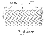
端部(782、786)が改変され且つ薬物送達が強化されたステントが提供される。このステント組立体は、また、隣接するステント間の重なりを強化する。A stent is provided with modified ends (782, 786) and enhanced drug delivery. This stent assembly also strengthens the overlap between adjacent stents.
Description
本発明は、移植可能な医療装置及び関連する製造及び使用方法に関する。より詳細には、移植可能な管腔内ステントに関する。 The present invention relates to implantable medical devices and related methods of manufacture and use. More particularly, it relates to an implantable intraluminal stent.
移植可能なステントは、10年以上の間に大きく発展し、多様な設計が研究され、体腔を開いておくためすなわち「開存」のための機械的骨組みを提供する際に使用するために市販されるようになっている。ステントは、一般に、特に血管を含めて、さらに詳細には冠動脈及び末梢動脈を含めて、多様な体腔に使用される。ステントの使用が開示されているその他の体腔としては、肺静脈、消化管、胆管、卵管及び精管が含まれる。さらに、これまでに、例えばシャントのような体内における人工的連絡又は移送のため及び経心筋血管再生術のために人為的に人工管腔が体内に作られてきたが、これらの体腔に使用するためのステントも開示されている。 Implantable stents have evolved significantly over the last decade, and various designs have been studied and marketed for use in providing a mechanical framework for keeping the body cavity open or "patent" It has come to be. Stents are generally used in a variety of body cavities, particularly including blood vessels, and more particularly including coronary and peripheral arteries. Other body cavities that disclose the use of stents include pulmonary veins, gastrointestinal tract, bile duct, fallopian tube and vas deferens. In addition, artificial lumens have been artificially created in the body for artificial communication or transfer in the body, such as shunts, and for transmyocardial revascularization, but are used for these body cavities. A stent for this purpose is also disclosed.
血管用ステントは、軸線を囲む壁を形成する一体化されたストラット網を形成するように互いに接続される構造ストラットの格子から形成される概略管状の部材である。一体化されたストラット格子は、一般に、ストラット間隙間を含み、これを通じて、ステント壁内の内部管腔軸線とステント壁を囲む外部領域とが連通可能となる。これは、例えば、側枝がステント壁の隙間を通じて主管腔から流れを有利に受けることができる動脈などの主管腔の長さに沿ってステントを移植する場合に有利である。 A vascular stent is a generally tubular member formed from a lattice of structural struts that are connected together to form an integrated strut network that forms a wall surrounding an axis. The integrated strut lattice generally includes an inter-strut gap through which an internal lumen axis within the stent wall and an external region surrounding the stent wall can communicate. This is advantageous, for example, when implanting a stent along the length of a main lumen, such as an artery, where the side branch can advantageously receive flow from the main lumen through the stent wall gap.
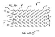
市販のステントの大部分は、完全に一体化された管状構造を構成し、一体化されたストラット格子に沿って周方向にも長さ方向にも連続性が見られる。潰れた状態(折畳み状態)と拡張状態との間で調節可能とするために、この種のステントは、一般に、ストラットに波形を取り入れている。この形状は、ステントの長さに沿った縦方向の変化を最小限に抑えながら半径方向の拡張性を最大限にするように形態を変えることを目的としている。これは、一般に、例えば、バルーン端部で膨張したバルーンの上をステントが覆う範囲を維持しながら、再開通される局所的疾患部位(例えば閉塞)の所望の長さに沿ってステントを反復して予測通りに配置するために、望ましい。そうでなければ、バルーンが膨張すると実質的に短くなるステントはバルーン端部を露出させて、この端部で局所的血管壁損傷を生じ、介入の完了後に長期間この部位を開通させておくと言うステント骨組の利点が得られない。 Most of the commercially available stents constitute a fully integrated tubular structure and are continuous in the circumferential and longitudinal directions along the integrated strut lattice. In order to be able to adjust between the collapsed state (folded state) and the expanded state, this type of stent generally incorporates a corrugation in the strut. This shape is intended to change form to maximize radial expandability while minimizing longitudinal variation along the length of the stent. This typically repeats the stent along the desired length of the local disease site (eg, occlusion) to be resumed while maintaining the extent of the stent covering the balloon inflated at the balloon end, for example. Is desirable in order to arrange as expected. Otherwise, a stent that becomes substantially shorter when the balloon is inflated will expose the end of the balloon, causing local vessel wall damage at this end, and leaving the site open for a long time after the intervention is complete. The advantage of the stent frame is not obtained.
上記で説明したタイプのステントが普及しているが、このような一般的構造をさらに修正するあるいは基本設計からさらに離れる他の設計も開示されている。例えば、別のタイプのステントは、周方向に連続的でなくストラット格子から構成されるシートに沿って二つの正反対側の端部を有する壁を形成する。このシートは、一方の端部から他方の端部までステントを巻くことによって潰れた状態に調整される。移植部位において、ステントは巻き解かれて、内部管腔の周りで管腔壁に係合する構造壁を形成する。ステントが管腔より小さい場合、両端部は重なった状態になるので、管腔壁から管腔内に突き出るインプラント材料の厚さが倍になる。 While stents of the type described above are prevalent, other designs have been disclosed that further modify this general structure or deviate further from the basic design. For example, another type of stent forms a wall having two diametrically opposite ends along a sheet composed of a strut lattice rather than being circumferentially continuous. The sheet is adjusted to a collapsed state by winding the stent from one end to the other end. At the implantation site, the stent is unwound to form a structural wall that engages the lumen wall around the inner lumen. If the stent is smaller than the lumen, the ends will overlap so that the thickness of the implant material protruding from the lumen wall into the lumen is doubled.
ステントは、バルーン式血管形成などの方法に付加的な介入的再疎通処置、または回転式アテローム切除装置及び方法などアテローム切除術に最もよく使用される。「バルーン拡張型」ステントは、一般に、空気を抜いたバルーンの外側表面に潰れた状態で送達され、その後バルーンを膨らませることによって対象となる管腔壁を圧して拡張状態に拡張するのに充分な延性を持ち、かつその後バルーンの空気を抜いたときインプラントとして実質的に拡張状態を保つ、例えばステンレス鋼又はコバルトクロム合金などの材料から構成される。「自己拡張型」ステントは、一般に、例えばニッケルチタン合金を含めた特定の合金など弾性、超弾性又は形状記憶材料で構成される。これらの材料は、一般に、拡張した記憶状態を有するが、適切な送達輪郭(デリバリプロファイル)を持つように潰れた状態で移植部位に送達される。所定の場所に達したら、ステントは解放されて正常な状態に復帰し、すなわち「自己拡張」し、管腔壁を圧する状態になり、そこにインプラントとして残される。 Stents are most often used for atherectomy such as interventional recanalization procedures, such as balloon angioplasty, or rotational atherectomy devices and methods. “Balloon expandable” stents are generally delivered in a collapsed state on the outer surface of a deflated balloon, which is then sufficient to compress the targeted lumen wall and expand it into an expanded state by inflating the balloon. It is made of a material such as stainless steel or cobalt-chromium alloy that has a good ductility and that remains substantially expanded as an implant when the balloon is subsequently deflated. “Self-expanding” stents are generally constructed of an elastic, superelastic or shape memory material, such as certain alloys including, for example, nickel titanium alloys. These materials generally have an expanded memory state, but are delivered to the implantation site in a collapsed state with an appropriate delivery profile. Once in place, the stent is released and returns to normal, i.e., "self-expanding", pressing the lumen wall, leaving it as an implant.
ステントは、一般に、開存を維持するためのものであるが、他の用途も開示されている。例えば、ステントが移植される対象となる管腔を閉塞するためのステントも開示されている。この種のステントの例としては、フィブリン被覆ステントがあり、この様なステントの閉塞用途の例としては、卵管結さつ及び動脈瘤閉鎖がある。 Stents are generally for maintaining patency, although other uses have been disclosed. For example, a stent for occluding a lumen into which the stent is to be implanted is also disclosed. An example of this type of stent is a fibrin-coated stent, and examples of such stent occlusion include fallopian tube ligation and aneurysm closure.
ステントは、さらに、「ステント−グラフト」を形成するためのグラフトなど他の構造との組立体に含まれたものもある。これらの組立体は、一般に、織物又はシート材料タイプの構造から構成されるものなどのグラフト材料に固定されるステント構造を備えている。ステント−グラフトについてこれまでに開示された用途の例としては、特に腹部大動脈壁に沿った動脈瘤隔離がある。 Stents may also be included in assemblies with other structures such as grafts to form a “stent-graft”. These assemblies generally comprise a stent structure that is secured to a graft material, such as that comprised of a fabric or sheet material type structure. Examples of applications disclosed so far for stent-grafts are aneurysm isolation, particularly along the abdominal aortic wall.
特に血管ステントの移植において、ステントは、血管再疎通処置後の「再狭窄」の発生に大きな影響を持っている。「再狭窄」は、急激に再疎通された閉塞部の再閉塞であり、典型的には介入後3〜6ヶ月以内に生じ、一般に、血管再疎通処置自体によって生じる血管壁の傷に対する機械的反応と生理学的反応の組み合わせによるものである。ある点に関して、再狭窄は、少なくとも部分的には、バルーン式血管形成術の際の血管壁拡張後などに、拡張された血管壁の弾性反跳から生じる可能性がある。傷に対する生理学的反応に関しては、血管壁の内膜層、内側層及び時には外膜層に対する血管再疎通による傷が、壁内の平滑筋細胞を攻撃性有糸分裂(攻撃に起因する細胞分裂)させて高増殖させ、血管に分け入り、入り込んで、血管を閉塞する「瘢痕」を形成することが一般的に観測されている。ステント留置術出現以前の血管形成及びその他の血管再疎通介入は、約30%の再閉塞率を示したが、ステント留置術は、この率を約20%に減少させた。この減少は、血管反跳の機械的防止の結果と考えられる。 Particularly in the implantation of vascular stents, the stent has a great influence on the occurrence of “restenosis” after vascular recanalization treatment. “Re-stenosis” is the re-occlusion of a rapidly re-occluded occlusion, typically occurring within 3 to 6 months after the intervention, and is generally mechanical to the vessel wall injury caused by the vascular re-canalization procedure itself. This is due to a combination of response and physiological response. In some respects, restenosis can result, at least in part, from elastic recoil of the expanded vessel wall, such as after vessel wall dilation during balloon angioplasty. Regarding the physiological response to wounds, wounds due to vascular recanalization to the intimal, inner and sometimes outer membrane layers of the vascular wall cause the smooth muscle cells in the wall to attack aggressive mitosis (cell division due to attack). It has been generally observed that they can be allowed to proliferate, enter and enter blood vessels, and form “scars” that occlude blood vessels. Angioplasty and other vascular recanalization interventions before the appearance of stenting showed a reocclusion rate of about 30%, but stenting reduced this rate to about 20%. This decrease is believed to be the result of mechanical prevention of vascular recoil.
血管ステント留置術における最近の労力は、再狭窄発生率をさらに下げるためにステント留置に付加的な治療添加剤を組み込むことに注がれてきた。例えば、ステント骨組み自体の中又は外側に放射性物質を組み込むことによって、ステント留置と同時に血管壁に局所的に治療放射線照射を与えるための努力がなされてきた。しかし、これらの努力は、材料の扱い及び処分のために手術中に大きな負担をもたらし、医療界においてはまだ成果が説得力を持つとは見なされていない。ステント端部の特定の態様を改変するための少なくとも一つの装置がさらに開示されている。しかし、特有の要件を持つ場所として特に近位端部に対処したものでもなく、近位端部だけに局所的に特有の構造が組み込まれたものでもない。さらに、放射性ステントを通じてなどによる局所的エネルギー送達は、拡散、流動又はその他の能動輸送機構の作用をその後に受けるステントからの物質及び化合物の局所的溶出送達とは大きく異なる。 Recent efforts in vascular stenting have focused on incorporating additional therapeutic additives into the stenting to further reduce the incidence of restenosis. For example, efforts have been made to provide therapeutic radiation locally to the vessel wall simultaneously with stent placement by incorporating radioactive material within or outside the stent framework itself. However, these efforts pose significant burdens during surgery for material handling and disposal, and the outcome has not yet been considered compelling in the medical community. Further disclosed is at least one device for modifying a particular aspect of the stent end. However, it does not specifically address the proximal end as a place with unique requirements, nor does it incorporate a locally unique structure only at the proximal end. Furthermore, local energy delivery, such as through a radioactive stent, is very different from local elution delivery of substances and compounds from the stent that are subsequently subjected to diffusion, flow or other active transport mechanisms.
さらに最近、特に再狭窄の発生を遅らせ防止するために、ステント留置病巣への局所的薬物送達を組み込むための大いなる産業上の努力も行われ続けている。例えば、拡張性バルーンの外皮に組み込まれる微細針などを通じて抗再狭窄物質を傷ついた壁に非常に局所的に注入するための様々な局所的送達装置が開示されている。 More recently, significant industrial efforts have also been made to incorporate local drug delivery to stented lesions, particularly to delay and prevent the occurrence of restenosis. For example, various local delivery devices have been disclosed for very locally injecting anti-restenotic material into a damaged wall, such as through a fine needle incorporated into the envelope of an expandable balloon.
しかし、移植後の定められた期間、ステントが血管壁に薬物を溶出するようにステント自体に抗再狭窄薬を組み込む(薬物溶出ステント”DES”として公知である)ために、さらに多くの努力が払われてきた。この用途の装置の例として、薬物を保持し溶出する外部コーティングを施されたステント構造を提供する被覆ステントがある。この種のコーティングの最も一般的な形態は、例えば特に商業的態様においては1層の薬物保持層及び溶出を遅らせる別の層を含む又は基礎ステント金属に付着させるための1層及び薬物を保持し溶出させる別の層を含む2層の重合体コーティングなど、重合体を含む。DESコーティングの他の例としては、セラミック、ヒドロゲル、生合成物質及び金属−薬物コーティングがある。DES法などを通じて再狭窄抑制用として研究された薬物の例としては、抗有糸分裂化合物、抗増殖化合物、抗炎症化合物及び抗遊走化合物がある。DES装置及び方法に使用するためにこれまでに開示された化合物の例としては、さらに、アンギオテンシン変換酵素(ACE)阻害薬、アンギオテンシン受容体拮抗薬、アンチセンス物質、抗血栓剤、血小板凝集阻害薬、イオンキレート化剤(例えば、エキソケリン)、エベロリムス、タクロリムス、血管拡張剤、酸化窒素及び酸化窒素促進剤又は供与体がある。 However, more effort has been made to incorporate an anti-restenosis drug into the stent itself (known as a drug eluting stent “DES”) so that the stent elutes the drug into the vessel wall for a defined period of time after implantation. Have been paid. An example of a device for this application is a coated stent that provides a stent structure with an outer coating that retains and elutes the drug. The most common form of this type of coating includes, for example, in one commercial embodiment, one drug retaining layer and another layer that delays dissolution, or one layer and drug for attachment to the base stent metal. A polymer is included, such as a two-layer polymer coating that includes another layer to be eluted. Other examples of DES coatings include ceramics, hydrogels, biosynthetic materials and metal-drug coatings. Examples of drugs studied for the prevention of restenosis through the DES method include antimitotic compounds, antiproliferative compounds, antiinflammatory compounds, and antimigratory compounds. Examples of compounds disclosed so far for use in DES devices and methods further include angiotensin converting enzyme (ACE) inhibitors, angiotensin receptor antagonists, antisense substances, antithrombotic agents, platelet aggregation inhibitors , Ion chelators (eg, exochelins), everolimus, tacrolimus, vasodilators, nitric oxide and nitric oxide promoters or donors.
DES装置に関してかなり臨床研究されてきた二つの特別な化合物には、Rapamycin(商標)(シロリムス)及びTaxol(商標)(パクリタキセル)がある。これらのDESの研究努力によって、ステント留置病巣における約20%という典型的な再狭窄率から約10%の再狭窄率に下げることに大きく近づき、特に特定の患者小集団に関してはさらにこの率を下げることが可能となった。 Two special compounds that have been extensively studied for DES devices are Rapamycin ™ (sirolimus) and Taxol ™ (paclitaxel). These DES research efforts have come very close to reducing the typical restenosis rate of about 20% in stented lesions to about 10% restenosis, especially for certain patient subpopulations. It became possible.
しかし、最近のシロリムス及びパクリタキセルDES臨床実績を考慮するとこのように大幅な改善が予想されるように見えるが、まだ様々なニーズはそのまま残されており、上記の及びその他のこれまでに開示されたDESによっては満たされていないと思われる。 However, considering the recent clinical performance of sirolimus and paclitaxel DES, it appears that such a significant improvement is expected, but various needs still remain, and the above and other previously disclosed It seems that some DES are not satisfied.
一つには、これらのDES臨床実績は、一般に、以前の非被覆ステントと実質的に同様の設計のステントインプラントを含んでおり、薬物送達を強化するためにこれらのステント設計にほとんど改変又は最適化が施されていない。しかし、ステントによって与えられる薬物送達は、ストラット形状及び溶出コーティングを運ぶ全体的格子設計によって特定目的に専用化される。 For one thing, these DES clinical achievements generally include stent implants of a design that is substantially similar to previous uncoated stents, with little or no modification to these stent designs to enhance drug delivery. Has not been applied. However, the drug delivery provided by the stent is dedicated to a particular purpose by the overall lattice design carrying the strut shape and the elution coating.
したがって、一般に、これらの特定のDES装置に予想される10%の再狭窄率は、以前の設計パラメータに加えて効力のある薬物の送達要件を満たすよう設計された改良型ステントを用いて薬物送達構造を改変することによって、さらに改善され得る。以前の設計パラメータは、過去においては、主に構造的骨組を提供すると言う機械的な配慮によって推進されてきた。 Thus, in general, the expected 10% restenosis rate for these particular DES devices is drug delivery using improved stents designed to meet the efficacy drug delivery requirements in addition to previous design parameters. Further improvements can be achieved by modifying the structure. Previous design parameters have been driven in the past by mechanical considerations that primarily provide a structural framework.
さらに具体的には、これまで開示された一部のDES臨床実験の結果及び関連する分析により、再狭窄を患う患者プール(患者集団)が減っているとは言うものの、ステントの端部が局所的な再狭窄増大の部位に関係していることが明らかにされた。さらに、この種の臨床データをより詳しく検討することにより、再狭窄とステント端部とのこの関連が、以下に示すように複数のそれぞれ特有の状況及び考慮すべき事項に関係することが明らかになる。 More specifically, the results of some of the DES clinical experiments disclosed so far and the associated analysis indicate that the patient pool (patient population) suffering from restenosis has decreased, but the end of the stent is localized. Was found to be related to the site of general restenosis augmentation. In addition, a closer examination of this type of clinical data reveals that this association between restenosis and stent end is related to several unique situations and considerations as shown below. Become.
一つには、単一の移植されたステント(例えば、非重なりステント)の端部、より具体的にはステントの端部に隣接する動脈「区域」は、再狭窄の局所的発生に関連している。ステントは、病巣部位に隣接する主管腔直径より僅かに大きい直径に拡張するように、下に位置する血管に対して多少「オーバーサイズ」の形態で移植されることが多い。したがって、一般にステンレス鋼、コバルトクロム又はその他の強度の高い金属で構成されるこの種の機械的構造は、ステントが留置されない隣接する血管壁との間で急激な遷移を生じさせる。さらに、少なくとも一つのDES開示によれば、この一般には非常に疎水性の高い薬物の溶出は、ステントストラット自体に隣接する組織に局所的にとどまることが明らかにされている。傷がステントの端部に隣接しているもののこの端部を越えて位置する限り、この傷はインプラントの長手方向の境界内で受けられるストラットからの薬物送達の恩恵を受けない。 For one, the end of a single implanted stent (eg, a non-overlapping stent), and more specifically, the arterial “segment” adjacent to the end of the stent, is associated with the local occurrence of restenosis. ing. Stents are often implanted in a somewhat “oversized” form to the underlying vessel to expand to a diameter slightly larger than the main lumen diameter adjacent to the lesion site. Thus, this type of mechanical structure, typically composed of stainless steel, cobalt chrome, or other strong metal, causes abrupt transitions between adjacent vessel walls where the stent is not deployed. Furthermore, at least one DES disclosure reveals that the elution of this generally very hydrophobic drug remains locally in the tissue adjacent to the stent strut itself. As long as the wound is adjacent to but beyond the end of the stent, the wound will not benefit from drug delivery from the struts received within the longitudinal boundaries of the implant.
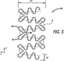
さらに、DESインプラントの近位端部(すなわち上流側端部)は遠位端部より高い再狭窄発生率を示すことが認められている。しかし、特に公表されているDES臨床実験において使用されたステントを含めて、ステントの近位端部は、ステントの遠位端部と同じ設計で構成されている。これらのステントの端部は、一般に、成形ストラット格子の波形サイクルの頂点すなわち最高点に形成されるが、頂点の形状は、曲げ部の平面内にとどまる傾向をなし従って血管−ステントの遷移部分の曲げモーメントに対する硬直性を増加させる構造となると考えられる。動脈の壁は一定の運動を示すので、この遷移部分は、時間を経ると、糜爛が生じる潜在的可能性を有する炎症相互作用の部位になると考えられる。さらに、薬物移動を行い従って溶出ステントストラットからの組織送達運動を行う移送機構が血管壁に沿って存在する限り、これは、一般に、例えば血管の流れと共に、また血管壁自体内部における栄養血管に関して、「下流」方向に流れると考えられる。 Furthermore, it has been observed that the proximal end (ie, upstream end) of the DES implant exhibits a higher rate of restenosis than the distal end. However, including the stents used in the published DES clinical experiments, the proximal end of the stent is configured with the same design as the distal end of the stent. The ends of these stents are generally formed at the apex or peak of the corrugated cycle of the shaped strut lattice, but the apex shape tends to remain in the plane of the bend, and thus the vessel-stent transition portion. It is thought that the structure increases the rigidity against the bending moment. Since the arterial wall exhibits constant motion, this transitional portion is thought to become a site of inflammatory interaction with the potential for wrinkling over time. In addition, as long as there is a transport mechanism along the vessel wall that performs drug movement and thus tissue delivery movement from the eluting stent struts, this is generally associated with, for example, vascular flow and with respect to trophic vessels within the vessel wall itself. It is thought to flow in the “downstream” direction.
したがって、典型的なDESステントインプラントの近位端部に隣接するこれから上流の血管壁組織は、最も広範囲に傷を受けるが抗再狭窄薬の送達は最も少ない可能性がある場所となる。ステントストラットからの薬物溶出量を増大させることによって、拡散がこのような部位に必要な治療効果を与えるかも知れない。しかし、これまでに開示されたDESの試みは、ステントに沿って一定の分量の薬物(その多くはある程度のレベルになると有毒である)を与えるものであり、過量の薬物を投与することにより害を与える結果となり得る。拡散によって上流組織に「達する」ために必要な用量を投与することは、潜在的に、ステントに沿って過量の薬物を与えることになり、「高用量投与」ステントの周りの改悪の結果、組織壊死及び動脈瘤を含めて害を生じる可能性がある。 Thus, the upstream vessel wall tissue adjacent to the proximal end of a typical DES stent implant will be the place where the most extensively wounded but anti-restenotic drug delivery may be least likely. By increasing the amount of drug elution from the stent struts, diffusion may provide the necessary therapeutic effect at such sites. However, the DES attempts disclosed so far provide a certain amount of drug along the stent, many of which are toxic at some level, and can be harmful by administering an excessive amount of drug. Can result. Administering the dose necessary to “reach” the upstream tissue by diffusion will potentially give an overdose of drug along the stent, resulting in tissue damage as a result of the “high dose” stent May cause harm, including necrosis and aneurysm.
これまでの開示は、局所的放射線不透過マーカーなどこれらの開示に示される特定の目標を果たすために端部に改変が施されたステントを含んでいた。しかし、これらの開示は、ステントの近位の上流側端部における固有の生体力学的要件には対処しきれていない。例えば、いくつかの先行開示は、ステントの端部に固有の設計を与えているが、これらのケースにおいては、両端部が同じ設計になっている。しかし、特に最初に窮屈な病巣を横切るために遠位の肩部(ショルダ)に最小限に小さい潰れプロファイルを与える可能性を含めて、ステントの遠位端部の設計において考慮しなければならない事項がいくつかある。このような考慮事項に従った設計は、ステントの近位端部に応用する必要はないが、このようなことについてはこれまで適切な考慮がなされていない。 Previous disclosures have included stents that have been modified at the ends to achieve the specific goals shown in these disclosures, such as local radiopaque markers. However, these disclosures do not address the inherent biomechanical requirements at the proximal upstream end of the stent. For example, some prior disclosures provide unique designs for the ends of the stent, but in these cases, the ends are the same design. However, things that must be considered in the design of the distal end of the stent, including the possibility of giving the distal shoulder a minimally small collapse profile, especially to cross a cramped lesion first There are several. A design according to such considerations need not be applied to the proximal end of the stent, but this has not been adequately considered so far.
したがって、特にステントの遠位端部及びステントの中間本体に対して特異な、これらとは異なる装置の近位端部に沿って一つ又は二つ以上の設計パラメータを強化する改良されたDES装置及び方法が、必要とされる。 Thus, an improved DES device that enhances one or more design parameters along the proximal end of a different device, particularly unique to the distal end of the stent and the intermediate body of the stent. And a method is needed.
また、ステントの遠位端部及びステントの中間本体とは異なるステントの近位端部に沿って薬物送達を強化する改良されたDES装置及び方法が依然として特に必要とされる。 There also remains a particular need for improved DES devices and methods that enhance drug delivery along the proximal end of the stent that is different from the distal end of the stent and the intermediate body of the stent.
また、ステントの上流縁端に沿って組織と装置との境界面の損傷、炎症及び/又は糜爛を最小限に抑える近位端部を有する改良されたステントが依然として特に必要とされる。 There also remains a particular need for an improved stent having a proximal end along the upstream edge of the stent that minimizes tissue-device interface damage, inflammation and / or wrinkles.
ステントの近位縁端に沿って特有の設計を与えることによって、例えば、生体での利用の際にこの全く異なる場所において果たす役割及び示される懸念を大きく減らすプロファイルのように、他の考慮事項を犠牲にして上記の必要性を満たすための大幅に改良を加えることができる。さらに、もしこれがプロファイルを犠牲にせずに可能であるなら、さらに多くの利益が近位縁端に付与され得る又はさらに多くの利益がこの有利な特徴を遠位端部に組み込めるようにすることによって付与され得る。 By providing a unique design along the proximal edge of the stent, other considerations such as, for example, the role played in this completely different location during biomedical use and the profile that greatly reduces the concerns presented. Significant improvements can be made to meet the above needs at the expense. Furthermore, if this is possible without sacrificing the profile, more benefits can be imparted to the proximal edge or by allowing more benefits to be incorporated into the distal end. Can be granted.
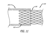
最近のDES臨床実験報告書によれば、患者集団内でいまだに残っているように思われる特に再狭窄発生が増大する他の場所は、ステントの両端部にも関係しており、「重なり」ステントに直接関係する。「重なりステント」は、本願においては、概略的に言うと、血管の長さ方向に沿って直列的に移植され、「重ねられる」複数のステントとして定義される。このような重なりは、第一のステントが所定の場所に配置されたのに対して、第二のステントが、血管に沿って一つの長いステント留置部位に連続性を与えるために、第一のステントに重なるように第一のステント内で拡張された後に、発生する。多くの開業医は、隣接するステントにこのような連続性を与えるためにこのような重なりを望み、移植された結果として、一般には(例えば、一つのステントの近位端部と他のステントの重なり遠位端部との間に)例えば約5ミリメートルの重なりができることを目標とする。開業医によっては、重なりの範囲をできる限り小さくしようとし、約1mmから約5mmの重なりが生じるのを目標とする。しかし、このような重なりは利益より大きな害をもたらすという信念に基づいて、このようなステントの重なりを特に避けようとする開業医はほとんどいない。 According to a recent DES clinical trial report, other locations where the occurrence of restenosis, particularly the rest of the patient population, which appears to remain, are also related to both ends of the stent, the “overlapping” stent. Directly related to An “overlapping stent” is generally defined herein as a plurality of stents that are implanted in series along the length of a blood vessel and “stacked”. Such an overlap is because the first stent is placed in place while the second stent provides continuity to one long stent placement site along the vessel. Occurs after being expanded in the first stent to overlap the stent. Many practitioners desire such overlap to give such continuity to adjacent stents, and as a result of implantation, generally (for example, the overlap of the proximal end of one stent and the other stent) The goal is to have, for example, an overlap of about 5 millimeters (with the distal end). Some practitioners try to make the overlap range as small as possible and aim to produce an overlap of about 1 mm to about 5 mm. However, few practitioners specifically try to avoid such stent overlaps based on the belief that such overlaps do more harm than good.
より具体的には、二つの対向するステントが重なった結果から得られる重なり格子構造は、ステント留置壁に沿った弱い流体力が重なり部位によって一層弱められ、その結果この領域において血栓形成の危険を増大させる可能性がある動脈など血液プール内においては、特に望ましくない。また、傷ついた血管壁に沿った血栓形成は、さらに、平滑筋細胞の高増殖の「昇圧因子」として、従って再狭窄の昇圧因子として報告されている。 More specifically, the overlapping lattice structure resulting from the overlap of two opposing stents is such that the weak fluid force along the stent placement wall is further attenuated by the overlap site, thereby reducing the risk of thrombus formation in this region. This is particularly undesirable in blood pools, such as arteries that may increase. In addition, thrombus formation along the damaged blood vessel wall is further reported as a “pressor factor” of hyperproliferation of smooth muscle cells, and thus as a factor of restenosis.
公表されている一部のDES臨床実験結果によれば、重なりステントにおける再狭窄の臨床的発生率は、使用されたそれぞれの装置及び方法によって、大幅に減少していると思われる。しかし、上述の公表された研究のうち少なくとも一つは、重なりステントの間の重なり帯域(ゾーン)における再狭窄がDES治療を受ける患者母集団全体内において特に高い頻度で依然として発生していることを指摘している。さらに具体的には、この研究において、被験母集団において認められた臨床的再狭窄の半分以上が、まさしく重なりステント間の重なり領域における巣状病変であった。 According to some published DES clinical experiment results, the clinical incidence of restenosis in overlapping stents appears to be significantly reduced with each device and method used. However, at least one of the published studies described above shows that restenosis in the overlapping zone (zone) between overlapping stents still occurs at a particularly high frequency within the entire patient population undergoing DES treatment. Pointed out. More specifically, in this study, more than half of the clinical restenosis observed in the study population was a focal lesion in the overlap area between the overlapping stents.
以上の観察結果にも関わらず、生体適合性及び長期的効果及びさらに特定すると特に重なりステントに関連する再狭窄を改善し強化するように特に設計されたステント又は組合せステント組立体はいまだにない。 Despite these observations, there are still no stents or combined stent assemblies specifically designed to improve and enhance the biocompatibility and long-term effects and more particularly the restenosis associated with overlapping stents.
したがって、さらに、別のステントと重ねるのに特に適し且つ長期的効果を向上させ、特に上述の重なりに関連する血栓形成及び再狭窄反応を減少させるように構成された移植可能な血管ステントが必要とされる。 Accordingly, there is a further need for an implantable vascular stent that is particularly suitable for overlaying with another stent and that enhances long-term effectiveness and is specifically configured to reduce thrombus formation and restenosis responses associated with the aforementioned overlap. Is done.
本発明の一つの態様は、特にステントの近位上流端部に沿って又はこれに隣接して長期的な開存性を改善させるように構成された移植可能な管腔内ステント組立体である。 One aspect of the present invention is an implantable endoluminal stent assembly configured to improve long-term patency, particularly along or adjacent to the proximal upstream end of the stent. .
本発明の他の態様は、ステントの残余の部分に対比してステントの端部に沿って局所的に特有な薬物送達を行うように構成された移植可能なDES装置及び方法である。 Another aspect of the present invention is an implantable DES device and method configured to provide locally specific drug delivery along the end of the stent relative to the remainder of the stent.
本発明の他の態様は、ステントの遠位端部に対比してステントの近位端部に沿って局所的に特有な薬物送達を行うように構成された移植可能なDES装置及び方法である。 Another aspect of the present invention is an implantable DES device and method configured to provide locally specific drug delivery along the proximal end of the stent relative to the distal end of the stent. .
本発明の他の態様は、ステントの残余の部分に対比してステントの近位端部に送達(デリバリ)される治療薬の用量を増加させるように構成された移植可能なDES装置及び方法である。 Another aspect of the present invention is an implantable DES device and method configured to increase the dose of therapeutic agent delivered to the proximal end of the stent relative to the remainder of the stent. is there.
本発明の他の態様は、ステントの残余の部分に沿った壁組織に対比して近位ステントの血管壁組織においてより密度の高いパターンで適用量の治療薬を送達(デリバリ)するように構成された移植可能なDES装置及び方法である。 Other aspects of the invention are configured to deliver a dose of therapeutic agent in a more dense pattern in the vessel wall tissue of the proximal stent as compared to the wall tissue along the remaining portion of the stent. An implantable DES device and method.
本発明の他の態様は、ステント端部における組織と装置との間の相互作用を改善させるように構成された、ステント端部に特有の局所的構造を有する移植可能なステントである。 Another aspect of the present invention is an implantable stent having a local structure unique to the stent end that is configured to improve the interaction between the tissue and the device at the stent end.
本発明の他の態様は、ステント留置病巣に関係する近位血管壁区域に沿った長期的開存性を改善させるように構成された、特にステントの近位端部の近位円頂に少なくとも一つの特有の局所的構造を有する移植可能なステントである。 Another aspect of the present invention is configured to improve long-term patency along the proximal vessel wall section associated with the stented lesion, particularly at least at the proximal crest of the proximal end of the stent. An implantable stent having one unique local structure.
本発明の他の態様は、ステントの遠位端部に対比してステントの近位端部に沿って特有の局所的構造を有する移植可能なステントであり、近位端部の特有の局所的構造は、少なくとも部分的にステントの遠位端部に対比してプロファイルの増大という犠牲を払ってステント近位端部の長期的開存性を強化するように構成されている。 Another aspect of the present invention is an implantable stent having a unique local structure along the proximal end of the stent relative to the distal end of the stent, The structure is configured to enhance the long-term patency of the proximal end of the stent at least partially at the expense of increased profile relative to the distal end of the stent.
本発明の他の態様は、ステントの遠位端部に対比してステントの近位端部に沿って特有の局所的構造を有する移植可能なステントであり、特有の局所的構造は、遠位端部より小さい隙間を有する近位端部に沿って、より高密度の円周パターンで薬物を送達するように構成されている。 Another aspect of the present invention is an implantable stent having a unique local structure along the proximal end of the stent relative to the distal end of the stent, wherein the unique local structure is distal. It is configured to deliver the drug in a denser circumferential pattern along the proximal end having a smaller gap than the end.
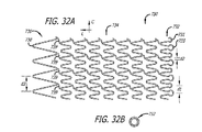
本発明の他の態様は、拡張状態においてステントの遠位端部より近位端部に沿って実質的により高い密度でストラットと組織との間で接触するパターンを与える、近位端部に沿って局所的に特有のストラット及び端部円頂のパターンを有する移植可能なステントである。 Other aspects of the invention provide a pattern of contact between the strut and tissue at a substantially higher density along the proximal end than the distal end of the stent in the expanded state along the proximal end. An implantable stent having a locally unique strut and end crest pattern.
本発明の他の態様は、以下のように、移植可能なステントとステントに結合される生体活性剤とを有する移植可能な管腔内ステント組立体である。ステントは、第一の端部を有する第一の端部部分と、第二の端部を有する第二の端部部分と、近位端部部分と遠位端部部分との間の本体部分と、第一の端部と第二の端部との間の長さと、第一の端部の第一の長手方向開口部と第二の端部の第二の長手方向開口部との間の長手方向軸線に沿った通路と、長手方向軸線周りの周と、長手方向軸線を横切る直径とを含む。ステントは、潰れ時直径を有する半径方向に潰れた状態で患者体内の管腔内の所定の位置に送達されるように構成されている。この所定の位置で、ステントは、半径方向に潰れた状態から、潰れ時直径より大きく且つ該所定の位置で管腔壁に係合するようになる拡張時直径を有する半径方向に拡張した状態に調整可能である。この所定の位置で半径方向に拡張した状態のステントは、生体活性物質に関して長さに沿って勾配が変化する溶出プロフィルを示す。 Another aspect of the invention is an implantable intraluminal stent assembly having an implantable stent and a bioactive agent coupled to the stent as follows. The stent includes a first end portion having a first end, a second end portion having a second end, and a body portion between the proximal end portion and the distal end portion. Between the first end and the second end, and the first longitudinal opening at the first end and the second longitudinal opening at the second end. Including a passage along the longitudinal axis, a circumference about the longitudinal axis, and a diameter across the longitudinal axis. The stent is configured to be delivered to a predetermined location within a lumen within a patient in a radially collapsed state having a collapsed diameter. In this predetermined position, the stent is moved from a radially collapsed state to a radially expanded state having an expanded diameter that is larger than the collapsed diameter and engages the lumen wall at the predetermined position. It can be adjusted. The stent in the radially expanded state at this predetermined location exhibits an elution profile with a gradient that varies along the length with respect to the bioactive agent.
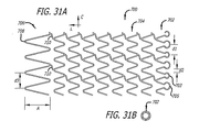
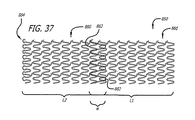
本発明の他の態様は、第一の端部を有する第一の端部部分と、第一の端部を有する第二の端部部分と、第一の端部部分と第二の端部部分との間の本体部分と、第一の端部と第二の端部との間の長さと、第一の端部の第一の長手方向開口部と第二の端部の第二の長手歩行開口部との間の長手方向軸線に沿って延びる通路と、長手方向軸線周りの周と、長手方向軸線を横切る直径とを含む移植可能なステントを有する移植可能な管腔内ステント組立体である。ステントは、潰れ時直径を有する半径方向に潰れた状態で患者体内の管腔内の所定の位置に送達されるように構成されている。この所定の位置において、ステントは、半径方向に潰れた状態から、潰れ時直径より大きく且つこの所定の位置で管腔壁に係合するようになる拡張時直径を有する半径方向に拡張した状態に調整可能である。この態様に関して、この所定の位置で半径方向に拡張した状態において、第一の端部部分は第一の格子構造を含み、第二の端部部分は第一の格子構造とは異なる第二の格子構造を含む。 Other aspects of the invention include a first end portion having a first end, a second end portion having a first end, a first end portion and a second end. A body portion between the portions, a length between the first end and the second end, a first longitudinal opening at the first end and a second at the second end An implantable endoluminal stent assembly having an implantable stent including a passage extending along a longitudinal axis between the longitudinal walking opening, a circumference about the longitudinal axis, and a diameter across the longitudinal axis. It is. The stent is configured to be delivered to a predetermined location within a lumen within a patient in a radially collapsed state having a collapsed diameter. In this predetermined position, the stent is moved from a radially collapsed state to a radially expanded state having an expanded diameter that is larger than the collapsed diameter and engages the lumen wall at the predetermined position. It can be adjusted. With respect to this aspect, in the radially expanded state at this predetermined location, the first end portion includes a first lattice structure, and the second end portion is a second different from the first lattice structure. Includes a lattice structure.
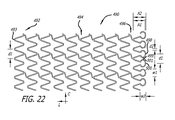
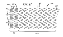
本発明の他の態様は、第一の端部を有する第一の端部部分と、第二の端部を有する第二の端部部分と、第一の端部部分と第二の端部部分との間の本体部分と、第一の端部と第二の端部との間の長さと、第一の端部の第一の開口部と第二の端部の第二の開口部との間の長手方向軸線に沿って延びる通路と、長手方向軸線周りの周と、長手方向軸線を横切る直径とを含む移植可能なステントを有する管腔内ステントシステムである。このステントは、潰れ時直径を有する半径方向に潰れた状態で患者体内の管腔内の所定の位置に送達されるように構成されている。この所定の位置において、ステントは、半径方向に潰れた状態から、潰れ時直径より大きく且つこの所定の位置で管腔壁に係合するようになる拡張時直径を有する半径方向に拡張した状態に調整可能である。半径方向に拡張した状態において、本体部分は第一の円頂間距離にわたる隙間によって周に沿ってそれぞれに分離される周方向に並んだ複数の本体円頂の周方向配列を有する少なくとも一つの長手方向セグメントを含む。さらに、半径方向に拡張した状態において、第二の端部部分は、第一の円頂間距離とは異なる第二の円頂間距離にわたる隙間によって周に沿ってそれぞれに分離される周方向に並んだ複数の端部円頂の周方向配列を含む。 Other aspects of the invention include a first end portion having a first end, a second end portion having a second end, a first end portion and a second end. A body portion between the portions, a length between the first end and the second end, a first opening at the first end and a second opening at the second end An intraluminal stent system having an implantable stent that includes a passage extending along a longitudinal axis therebetween, a circumference about the longitudinal axis, and a diameter across the longitudinal axis. The stent is configured to be delivered to a predetermined location within a patient body lumen in a radially collapsed state having a collapsed diameter. In this predetermined position, the stent is moved from a radially collapsed state to a radially expanded state having an expanded diameter that is larger than the collapsed diameter and engages the lumen wall at the predetermined position. It can be adjusted. In the radially expanded state, the body portion has at least one longitudinal section having a circumferential array of a plurality of body vertices arranged in a circumferential direction separated from each other along the circumference by a gap spanning a first inter-cusp distance. Includes direction segments. Further, in the radially expanded state, the second end portions are circumferentially separated from each other along the circumference by a gap across a second inter-crest distance that is different from the first inter-crest distance. It includes a circumferential array of a plurality of end circles arranged side by side.
本発明の他の態様は、第一の端部を有する第一の端部部分と、第二の端部を有する第二の端部部分と、第一の端部部分と第二の端部部分との間の本体部分と、第一の端部と第二の端部との間の長さと、第一の端部の第一の長手方向開口部と第二の端部の第二の長手方向開口部との間の長手方向軸線に沿って延びる通路と、長手方向軸線周りの周と、長手方向軸線を横切る直径とを含む移植可能なステントを有する移植可能な管腔内ステント組立体である。ステントは、潰れ時直径を有する半径方向に潰れた状態で患者体内の管腔内の所定の位置に送達されるように構成されている。この所定の位置において、ステントは、半径方向に潰れた状態から、潰れ時直径より大きく且つこの所定の位置で管腔壁に係合するようになる拡張時直径を有する半径方向に拡張した状態に調整可能である。ステントは、第一の端部部分と第二の端部部分との間において周の方向に所定のパターンで配置される格子構造で構成される。第一の端部部分及び第二の端部部分に沿った格子構造は、周方向に並んだ複数の端部円頂の周方向配列を含む。半径方向に潰れた状態において、第一の端部部分及び第二の端部部分の少なくとも一方に沿った端部円頂の周方向配列が重ねられるのに対して、本体部分に沿った格子構造は重なり領域を含まない。 Other aspects of the invention include a first end portion having a first end, a second end portion having a second end, a first end portion and a second end. A body portion between the portions, a length between the first end and the second end, a first longitudinal opening at the first end and a second at the second end An implantable endoluminal stent assembly having an implantable stent that includes a passage extending along a longitudinal axis between the longitudinal opening, a circumference about the longitudinal axis, and a diameter across the longitudinal axis. It is. The stent is configured to be delivered to a predetermined location within a lumen within a patient in a radially collapsed state having a collapsed diameter. In this predetermined position, the stent is moved from a radially collapsed state to a radially expanded state having an expanded diameter that is larger than the collapsed diameter and engages the lumen wall at the predetermined position. It can be adjusted. The stent has a lattice structure arranged in a predetermined pattern in the circumferential direction between the first end portion and the second end portion. The lattice structure along the first end portion and the second end portion includes a circumferential array of a plurality of end peaks arranged in the circumferential direction. In a collapsed state in the radial direction, the circumferential array of end vertices along at least one of the first end portion and the second end portion is superimposed, whereas the lattice structure along the body portion Does not include overlapping regions.
本発明の他の態様は、第一の端部を有する第一の端部部分と、第二の端部を有する第二の端部部分と、第一の端部部分と第二の端部部分との間の本体部分部と、第一の端部と第二の端部との間の長さと、第一の端部の第一の長手方向開口部と第二の端部の第二の長手方向開口部との間の長手方向軸線に沿って延びる通路と、長手方向軸線周りの周と、長手方向軸線を横切る直径とを含む移植可能なステントを有する移植可能な管腔内ステント組立体である。ステントは、非超弾性の非形状記憶合金材料で構成される格子構造を含む。ステントは、格子構造が初期直径の初期記憶状態から塑性変形される潰れ時直径を有する半径方向に潰れた状態で、患者体内の管腔内の所定の位置に送達されるように構成されている。この所定の位置において、格子構造は、力を受けて、半径方向に潰れた状態から、潰れ時直径より大きく且つこの所定の位置で管腔壁に係合するようになる拡張時直径を有する半径方向に拡張した状態に調整可能である。格子構造の初期直径は、潰れ時直径よりは拡張時直径に近い値である。 Other aspects of the invention include a first end portion having a first end, a second end portion having a second end, a first end portion and a second end. A body part between the parts, a length between the first end and the second end, a first longitudinal opening at the first end and a second at the second end An implantable endoluminal stent set having an implantable stent that includes a passage extending along a longitudinal axis between the longitudinal opening of the tube, a circumference about the longitudinal axis, and a diameter across the longitudinal axis It is a solid. The stent includes a lattice structure composed of a non-superelastic non-shape memory alloy material. The stent is configured to be delivered to a predetermined location within a lumen within a patient body with the lattice structure collapsed radially with a collapsed diameter that is plastically deformed from an initial memory state of the initial diameter. . In this predetermined position, the lattice structure is subjected to a force and has a radius having an expanded diameter that is larger than the collapsed diameter and engages the lumen wall at the predetermined position from a radially collapsed state. It can be adjusted to expand in the direction. The initial diameter of the lattice structure is closer to the expanded diameter than the collapsed diameter.
本発明の他の態様は、患者体内の管腔内の所定の位置に移植される少なくとも一つのステントを提供するためのキットである。これは、各々が、近位端部部分と、近位端部部分が患者の体外に延びた状態で前記所定の位置に配置されるように構成された遠位端部部分とを有する第一の送達システム及び第二の送達システムを含む。また、各々が、第一の端部を有する第一の端部部分と、第二の端部を有する第二の端部部分と、第一の端部部分と第二の端部部分との間の本体部分と、第一の端部と第二の端部との間の長さと、第一の端部の第一の開口部と第二の端部の第二の開口部との間の長手方向軸線に沿って延びる通路と、長手方向軸線周りの周と、長手方向軸線を横切る直径とを含む移植可能な第一のステント及び第二のステントも含まれる。第一の端部部分の各々は、対応する本体部分に沿った格子構造とは異なり且つそれぞれのステントの対応する第二の端部部分に沿った格子構造とも異なる格子構造を含む。第一のステントは、第一の端部が第二の端部の近位側に配置されるように、第一の送達システムの遠位端部部分に結合される。第二のステントは、第一の端部が第二の端部の遠位側に配置されるように、第二の送達システムの遠位端部部分に結合される。第一のステント及び第二のステントは、それぞれの潰れ時直径を有する半径方向に潰れた状態で、それぞれ、第一の送達システム及び第二の送達システムによって前記所定の位置に送達されるように構成されている。この所定の位置において、ステントの各々は、それぞれの半径方向に潰れた状態から、それぞれの潰れ時直径より大きく且つこの所定の位置で管腔壁に周方向に係合するようになる拡張時直径を有する半径方向に拡張した状態に調整可能である。 Another aspect of the invention is a kit for providing at least one stent to be implanted at a predetermined location within a lumen within a patient. This includes a first end portion each having a proximal end portion and a distal end portion configured to be disposed in the predetermined position with the proximal end portion extending out of the patient's body. And a second delivery system. Each of a first end portion having a first end, a second end portion having a second end, a first end portion and a second end portion; Between the main body portion, the length between the first end and the second end, and the first opening at the first end and the second opening at the second end Also included are implantable first and second stents that include a passage extending along the longitudinal axis, a circumference about the longitudinal axis, and a diameter across the longitudinal axis. Each of the first end portions includes a lattice structure that is different from the lattice structure along the corresponding body portion and different from the lattice structure along the corresponding second end portion of the respective stent. The first stent is coupled to the distal end portion of the first delivery system such that the first end is disposed proximal to the second end. The second stent is coupled to the distal end portion of the second delivery system such that the first end is disposed distal to the second end. The first stent and the second stent are delivered to the predetermined location by the first delivery system and the second delivery system, respectively, in a radially collapsed state having respective collapsed diameters. It is configured. In this predetermined position, each of the stents expands from their respective radially collapsed state to a larger diameter than their respective collapsed diameters and to engage the lumen wall circumferentially at this predetermined position. And can be adjusted to a radially expanded state.
本発明の他の態様は、各々が、第一の端部を有する第一の端部部分と、第二の端部を有する第二の端部部分と、第一の端部と第二の端部との間の本体部分と、第一の端部と第二の端部との間の長さと、第一の端部の第一の開口部と第二の端部の第二の開口部との間の長手方向軸線に沿って延びる通路と、長手方向軸線周りの周と、長手方向軸線を横切る直径とを含む移植可能な第一のステント及び第二のステントを含む移植可能な管腔内ステント組立体である。生体活性剤が第一のステント及び第二のステントの各々に結合される。第一のステント及び第二のステントは、ステント留置区域全長にわたって患者体内の管腔壁に沿ったそれぞれの対面する端部部分の間で部分的重なり配置で移植されるように構成され、重なり端部を含む重なり帯域が壁に沿ってステント留置区域全長より小さい距離である。第一のステント及び第二のステントの重なり配置は、ステント留置区域全長に沿って生体活性剤の結合溶出プロフィルを示すように構成されている。重なり帯域に沿った溶出プロフィルは、ステント留置区域の残余の部分に沿った薬物溶出プロフィルの二倍より実質的に少ない。 Other aspects of the invention include a first end portion having a first end, a second end portion having a second end, a first end and a second end. A body portion between the ends, a length between the first end and the second end, a first opening at the first end and a second opening at the second end An implantable tube comprising a first implantable stent and a second stent comprising a passage extending along a longitudinal axis between the sections, a circumference about the longitudinal axis, and a diameter across the longitudinal axis An intraluminal stent assembly. A bioactive agent is bound to each of the first stent and the second stent. The first stent and the second stent are configured to be implanted in a partially overlapping arrangement between respective facing end portions along the lumen wall within the patient over the entire stent placement area. The overlap zone including the portion is a distance along the wall that is less than the total stent placement area. The overlapping arrangement of the first and second stents is configured to exhibit a bioactive agent binding elution profile along the entire stent placement area. The elution profile along the overlap zone is substantially less than twice the drug elution profile along the remainder of the stent placement area.
本発明の他の態様は、患者体内の管腔壁にステントを留置するための方法である。この方法は、潰れ時直径を有する半径方向に潰れた状態でステントを管腔内の所定の位置に送達するステップと、この所定の位置において、半径方向に潰れた状態から、潰れ時直径より大きく且つこの所定の位置で管腔壁に係合するようになる拡張時直径を有する半径方向に拡張した状態にステントを調整するステップと、ステントの長さに沿って勾配が変化する用量送達プロフィルに従ってこの所定の位置において管腔壁に生体活性剤を送達するステップとを含む。 Another aspect of the present invention is a method for placing a stent in a lumen wall within a patient. The method includes delivering a stent to a predetermined location within a lumen in a radially collapsed state having a collapsed diameter, and from the radially collapsed state at the predetermined location to a diameter greater than the collapsed diameter. And adjusting the stent to a radially expanded state having an expanded diameter that will engage the lumen wall at this predetermined location, and according to a dose delivery profile in which the gradient varies along the length of the stent. Delivering a bioactive agent to the lumen wall at the predetermined location.
本発明の他の態様は、ステントの一つの端部に沿って周方向に並んだ複数の端部円頂の周方向配列が重なり配置であるが、ステントの本体円頂は重ねられない半径方向に潰れた状態でステントを提供するステップを含む、ステントを提供するための方法である。重なり端部円頂は、管腔壁に沿って移植されるように構成された半径方向に拡張した状態において周方向に広がるように構成されている。 Another aspect of the present invention is a radial arrangement in which a circumferential array of a plurality of end vertices arranged circumferentially along one end of the stent is overlaid, but the main body crests of the stent do not overlap. A method for providing a stent comprising providing a stent in a collapsed state. The overlapping end crest is configured to expand in the circumferential direction in a radially expanded state configured to be implanted along the lumen wall.
本発明の他の態様は、患者体内の管腔内の所定の位置に使用するための移植可能な管腔内ステント組立体を提供する方法である。この方法は、第一の端部を有する第一の端部部分と、第二の端部を有する第二の端部部分と、第一の端部部分と第二の端部部分との間の本体部分と、第一の端部と第二の端部との間の長さと、第一の端部の第一の長手方向開口部と第二の端部の第二の長手方向開口部との間の長手方向軸線に沿って延びる通路と、長手方向軸線周りの周と、長手方向軸線を横切る直径とを含む移植可能なステントを形成するステップを含む。形成されるステントは非超弾性の非形状記憶合金材料で構成される格子構造を含み、格子構造は初期直径を有する初期記憶状態に形成される。この方法は、さらに、初期直径を有する初期記憶状態から、初期記憶状態から塑性変形され且つ患者体内の管腔内の所定の位置に送達されるように構成された潰れ時直径を有する半径方向に潰れた状態に、格子構造を調整するステップを含む。格子構造は、力を受けて、半径方向に潰れた状態から、潰れ時直径より大きく且つこの所定の位置で管腔壁に係合するように構成された拡張時直径を有する半径方向に拡張した状態に調整可能である。この方法に関して、初期直径は、潰れ時直径よりは拡張時直径に近い値である。 Another aspect of the present invention is a method for providing an implantable endoluminal stent assembly for use at a predetermined location within a lumen within a patient. The method includes: a first end portion having a first end; a second end portion having a second end; and a first end portion and a second end portion. A body portion, a length between the first end and the second end, a first longitudinal opening at the first end and a second longitudinal opening at the second end Forming an implantable stent including a passage extending along a longitudinal axis therebetween, a circumference about the longitudinal axis, and a diameter across the longitudinal axis. The formed stent includes a lattice structure composed of a non-superelastic non-shape memory alloy material, and the lattice structure is formed in an initial memory state having an initial diameter. The method further includes, from an initial memory state having an initial diameter, radially having a collapsed diameter configured to be plastically deformed from the initial memory state and delivered to a predetermined location within a lumen within the patient. Adjusting the lattice structure to a collapsed state. The lattice structure is subjected to force to radially expand from a radially collapsed state having an expanded diameter that is larger than the collapsed diameter and configured to engage the lumen wall at this predetermined location. It can be adjusted to the state. For this method, the initial diameter is closer to the expanded diameter than the collapsed diameter.
本発明の他の態様は、患者体内の管腔内の所定の位置の壁にステントを留置するための方法である。この方法は、第一のステントを管腔内の第一の移植位置に送達するステップと、管腔内において第一の移植位置と重なる第二の移植位置に第二のステントを送達して、第一のステント及び第二のステントの対面する端部が重なるようにするステップとを含む。第一のステント及び第二のステントの各々の対面する端部は、それぞれのステントの残余の部分に沿った格子構造とは異なる格子構造を含む。 Another aspect of the present invention is a method for placing a stent on a wall in place within a lumen within a patient. The method includes delivering a first stent to a first implantation location within the lumen; delivering the second stent to a second implantation location overlapping the first implantation location within the lumen; The facing ends of the first stent and the second stent overlap. The facing ends of each of the first and second stents include a lattice structure that is different from the lattice structure along the remainder of the respective stent.
本発明の他の態様は、患者体内の管腔の所定の位置の壁にステントを留置するための方法であり、管腔内の第一の移植位置に第一のステントを送達するステップと、管腔内において第一の移植位置と重なる第二の移植位置に第二のステントを送達して、第一のステント及び第二のステントの対面する端部が重なり帯域で重なるようにするステップと、重なり帯域における溶出プロフィルがステント留置区域の残余の部分に沿った溶出プロフィルの二倍より実質的に小さいように、第一のステント及び第二のステントから生体活性剤を溶出させるステップとを含む。 Another aspect of the present invention is a method for deploying a stent to a predetermined wall of a lumen in a patient body, delivering the first stent to a first implantation location within the lumen; Delivering a second stent in a lumen to a second implantation location that overlaps the first implantation location such that the facing ends of the first stent and the second stent overlap in an overlap zone; Eluting the bioactive agent from the first and second stents such that the dissolution profile in the overlap zone is substantially less than twice the dissolution profile along the remainder of the stent placement area. .
以上の態様、形態及び実施形態の各々は、他のものと組み合わせる必要なく単独で有益であると考えられる。しかし、このような組み合わせは当業者には可能であり、さらなる単独の利益を与えるものとして想定される。 Each of the above aspects, forms and embodiments is considered to be beneficial alone without having to be combined with others. However, such combinations are possible to those skilled in the art and are envisioned as providing additional single benefits.
本発明のさらなる目的及び利点は、明細書の以下の部分において明らかにされるが、詳細な説明は、本発明を限定するものではなく本発明の好ましい実施形態を充分に開示するためのものである。 Further objects and advantages of the present invention will become apparent in the following portions of the specification, but the detailed description is not intended to limit the invention but to fully disclose preferred embodiments of the invention. is there.
本発明は、例示のためにのみ示される添付図面を参照することによってより良く理解できるであろう。
図面についてより詳細に述べると、例示のために、本発明は図1Aから図38までに概略的に示される装置として具現化される。大まかに言うと、様々な実施形態は、薬物溶出ステントの成果を向上させるための強化を与え、ステント骨組みは生体活性剤を搬送し且つ溶出させるように構成されていることが分かるはずである。このような物質は、例えばステント骨組みの表面のコーティングにおいて又はコーティングとして、若しくは薬物を保持し溶出するステント骨組に沿って形成されるウェル(穴)又は窪み内に与えることができる。このような様々な強化は薬物搬送形態の特定の様式に限定されるものではなく、薬物溶出ステントに関する他の入手可能な情報を考慮して本開示を精査すれば当業者には明らかなように、特に説明される形態以外の形態が考えられる。また、本発明の強化によって薬物溶出ステントには様々な利点が与えられるが、このような様々な特徴は、薬物溶出の有無に関わらずステントシャーシに大きな利点を与えることが分かるはずであるし、また、地金ステント骨組の組み込み及び強化など他の状況において有利であると見なされるはずである。
The invention may be better understood with reference to the following drawings, which are shown for illustrative purposes only.
Referring to the drawings in more detail, for purposes of illustration, the present invention is embodied as an apparatus schematically shown in FIGS. 1A-38. Broadly speaking, it should be appreciated that the various embodiments provide enhancements to improve the performance of drug eluting stents, and that the stent framework is configured to deliver and elute bioactive agents. Such material can be provided, for example, in a coating on the surface of the stent framework or in a well or hole formed along the stent framework that retains and elutes the drug. These various enhancements are not limited to a particular mode of drug delivery configuration, as will be apparent to those of skill in the art upon reviewing the present disclosure in view of other available information regarding drug eluting stents. Other forms than those specifically described are conceivable. The enhancements of the present invention also provide various advantages to drug eluting stents, and it should be understood that these various features provide significant advantages to the stent chassis with or without drug eluting, It should also be considered advantageous in other situations, such as the incorporation and reinforcement of bare metal stent frames.
本出願において開示される基本概念から逸脱することなく、本発明の装置は構成及び部品の細部に関して変化する可能性があり、また、本発明の方法は特定のステップ及び手順に関して変化する可能性があることが分かるだろう。 Without departing from the basic concepts disclosed in this application, the apparatus of the present invention may vary with respect to configuration and part details, and the method of the present invention may vary with respect to specific steps and procedures. You will see that there is.
図において様々に示されているように、様々なステントの実施形態は、例示のために長手方向軸線Lに沿ってチューブに長手方向に形成される切り口に従って「広げられた」状態で示される管状壁を備える。したがって、ステントの円周は、長手方向軸線Lを横切る周方向軸線Cに沿って平らに示されている。このような配置を示す様々な図面に関して、ステント壁の平らな図解の上辺は、一般に、長手方向軸線Lに沿ってステントの周壁を形成するためにこの平らな図解の底辺と合わせられ、このとき、長手方向軸線Lを横切るように示される周方向軸線Cは、長手方向軸線Lの周りに巻きつくように改変されるのに対して、半径方向軸線(図示されていない)が、長手方向軸線Lを横切る軸線として、周方向軸線Cに取って代わる。 As variously shown in the figures, various stent embodiments are shown tubular in an “unfolded” state according to a cut formed longitudinally in the tube along the longitudinal axis L for illustrative purposes. Provide walls. Thus, the circumference of the stent is shown flat along a circumferential axis C across the longitudinal axis L. With respect to the various drawings showing such an arrangement, the top side of the flat illustration of the stent wall is generally aligned with the bottom side of this flat illustration to form the peripheral wall of the stent along the longitudinal axis L, where The circumferential axis C, shown transverse to the longitudinal axis L, is modified to wrap around the longitudinal axis L, whereas the radial axis (not shown) is It replaces the circumferential axis C as the axis crossing L.
各図面に関して当業者には明らかなように、図面によってはこの配置に従ったステントの全体図を示し、図面によってはこの構成の部分図を示していることが分かるはずである。このような構造は、平らに「広げられて」形成され、その後平らなシートから切断又はエッチングするなどして最終的な環状ステント製品に形成することができる。あるいはまた、長手方向軸線Lに沿ってリングセグメントからリングセグメントに溶接又はその他の方法で固定されるリングから形成するか、または中実ハイポチューブなど管状原材料から切断又はエッチング加工することができる。このような形成技術は、当業者には明らかなように、レーザ切断、フォトエッチング、機械的切断、打ち抜き、化学的エッチングなどを使用することができる。 As will be apparent to those skilled in the art with respect to each drawing, it should be understood that some drawings show an overall view of the stent according to this arrangement, and some drawings show a partial view of this configuration. Such a structure can be formed "flattened" flat and then formed into the final annular stent product, such as by cutting or etching from a flat sheet. Alternatively, it can be formed from a ring that is welded or otherwise secured to the ring segment along the longitudinal axis L, or cut or etched from a tubular raw material such as a solid hypotube. Such formation techniques can use laser cutting, photoetching, mechanical cutting, stamping, chemical etching, etc., as will be apparent to those skilled in the art.
特に図1A〜図1Cを参照すると、これらの図は、ステント10が下記のように端部12に沿って強化されたある特徴を有する、本発明の一つの実施形態の様々な細部を示している。 With particular reference to FIGS. 1A-1C, these figures illustrate various details of one embodiment of the present invention in which the stent 10 has certain features reinforced along the end 12 as described below. Yes.
図1Aに示されているように、端部12は、半径方向軸線Rに関して隣接する複数の端部円頂(端部クラウン)を含む。端部円頂は、例としてそれぞれ収束する1対のストラットセグメント14と18の間の端部円頂16又はそれぞれ収束する1対のストラットセグメント34と38の間の隣接する端部円頂36に示されるように、収束する互いに隣接するストラットセグメントの間に形成される接合領域である。これらの端部円頂は、例として隣接する端部円頂16及び36に示されるように、長手方向軸線Lに関して同じ方向を向いており且つステント10の端部のストラットセグメントの波形パターンの基本的に交互に現れる頂点(ピーク)である。半径方向軸線Rに沿って示される蛇行パターンにしたがって、例えば端部円頂16と36との間など隣接する端部円頂間の距離d1は、端部12の波形蛇行パターンの完全な360度サイクルを表す。端部円頂16と反対を向く円頂26との間の距離など、一つの端部円頂とステントの中央を向く反対方向を指す次のピークとの間の半径方向軸線Rに沿った距離は、軸線Rに沿った蛇行サイクルの180度部分(又は半分)を表す。これらの隣接する円頂16と26の間の距離は、図1Aにおいて潰れた状態での振幅A1として示される端部12の蛇行パターンの振幅を表す。
As shown in FIG. 1A, the end 12 includes a plurality of end crests (end crowns) that are adjacent with respect to the radial axis R. The end crests are, for example, at the
この特定の波形サイクル及び固有の蛇行形状のタイプは例として選ばれており、非常に有利ではあるが、当業者には明らかなように、他のストラット/円頂パターンに応用可能な特定の広範な態様を限定することを意図するものではない。 This particular waveform cycle and inherent serpentine shape type has been chosen as an example and is very advantageous, but as will be apparent to those skilled in the art, a particular wide range of applications applicable to other strut / top patterns. It is not intended to limit the particular embodiment.
図1Aのステント10は、参考として図1A〜図1Bにおいてストラットセグメント14、18に沿った拡大部15、17に示されるように、端部円頂を形成する収束する対である隣接するステントのストラットセグメントの外側表面に沿って離散的な複数の拡大部を含む。逆に言うと、拡大部は、交互の隣接する端部円頂を形成する端部12の方向に分岐するストラットセグメントの対面する面に沿って配置される。さらに別の観点で説明すると、これらの拡大部15、17は、内向き本体円頂26を形成する谷部内の収束するストラットセグメントの対面する表面にある。以上の説明は各々異なる観点から同じ配置について述べており、いずれにしても、拡大部は、端部12に担持される薬物の量を増大させる。
The stent 10 of FIG. 1A is a reference of an adjacent stent that is a converging pair forming an end crest, as shown by the
この拡大部は様々な位置に配置することができる。図に示される特定の実施形態においては、図に示されているように隣接する端部円頂の間のストラットセグメントに拡大部を設けることによって、ステント端部の硬直性への拡大部の影響を減少する。さらに具体的には、本実施形態において例示されるストラット/円頂構成において、図1Aに示される半径方向に潰れた状態から図1Bに示される半径方向に拡張した状態への拡張中に生じる曲がりのほとんどは主に円頂部に生じる。逆に言うと、円頂間に延びるストラットセグメントは、拡張中、主に周方向に周方向軸線Cに対して相対的に回転する。したがって、円周は、図1Aのd1と図1Bのd2を比較することによって示されるように、円頂間の距離が拡大することによって、図1Aから図1Bに拡大する。このような半径方向の拡張は、さらに反対向きの隣接する円頂16と26との間の振幅A2(図1B)およびA1(図1A)など反対向きの隣接する円頂間の波形サイクルの振幅を減少させる。ストラットセグメントが回転する角度及びそれぞれの円頂の曲率半径に関する角度が、ストラットセグメント18及び34の間の角度を参考にして、図1Cにさらに詳しく示されている。巣トラッドセグメント18及び34は、収束して本体円頂26を形成している、逆に言えば、分岐して、隣接する端部円頂16、36を部分的に形成している。ステントを図1Aの潰れた状態から図1Bの拡張した状態に調整するために角度を拡大することによって、ストラット18、34の対面する拡大部17、35は、それぞれ周方向軸線Cに関して互いに引き離されるが、図1Bに示されるように、距離d2の幅を持つ隣接する円頂16、36間の拡大した隙間への薬物送達を増大させることができる配置となる。
This enlarged portion can be arranged at various positions. In the particular embodiment shown in the figure, the effect of the enlargement on the stiffness of the stent end by providing an enlargement in the strut segment between adjacent end vertices as shown in the figure. Decrease. More specifically, in the strut / circular top configuration exemplified in the present embodiment, the bending that occurs during expansion from the radially collapsed state shown in FIG. 1A to the radially expanded state shown in FIG. 1B. Most of this occurs mainly at the top of the circle. Conversely, the strut segments extending between the crests rotate relative to the circumferential axis C mainly in the circumferential direction during expansion. Thus, the circumference expands from FIG. 1A to FIG. 1B as the distance between the vertices increases, as shown by comparing d1 in FIG. 1A and d2 in FIG. 1B. Such radial expansion further increases the amplitude of the waveform cycle between adjacent opposite vertices, such as amplitudes A2 (FIG. 1B) and A1 (FIG. 1A) between adjacent
ストラット/円頂セグメントの波数、サイズ、形状又は位置並びにストラット及び円頂に対して相対的な拡大部など様々なパラメータが変化し得ることが分かるはずである。 It should be appreciated that various parameters such as the wave number, size, shape or position of the strut / circular segment and the enlargement relative to the strut and the circular apex can vary.
例えば、図2のステントセグメント50の分解図を参照すると、拡大部57、77は、収束して本体円頂66を形成し反対方向に分岐してそれぞれ端部円頂56、76を部分的に形成するストラット58、74の対面する側面に配置される。これらの拡大部は、図に示される潰れた状態において重ならないように、波形サイクルの振幅A内で長手方向軸線Lに沿って多少異なる位置にある。さらに、拡大部をそれぞれストラット58、74の位置59、79に動かすことができる。あるいはまた、各拡大部がストラット58、74の間の対面する拡大部と合致しない領域内に収まる鍵状配置においては、ストラット58上の拡大部57及び59及びストラット74上の拡大部77及び79のように複数の拡大部を備えることができる。
For example, referring to the exploded view of the
拡大部は、図1A〜図1Cに示されるように、互いに直接対面する配置を含めて他の構成でも配置でき、このような構成においては潰れた状態においては拡大部が重なるか、あるいは図1Aに示されるように、周方向軸線Cに沿って互いに達しないように潰れた状態を制限することができることが分かるはずである。さらに、拡大部は、図3に示されるステント端部60の正反対向きの円頂62、68の間のストラット64の正反対向きの面の拡大部65、67のように、ストラットの両側に備えることができる。内向き拡大部67は、拡張状態において端部円頂62と隣接する端部円頂(図には示されていない)との間の「隙間を塞ぐ」ようには配置されないが、ステントの端部60の全体領域にさらにより多くの薬物を供給するのに役立つ。
As shown in FIGS. 1A to 1C, the enlarged portion can be arranged in other configurations including an arrangement that directly faces each other. In such a configuration, the enlarged portions overlap in a collapsed state, or FIG. It should be understood that the collapsed state can be limited so as not to reach each other along the circumferential axis C, as shown in FIG. Further, the enlarged portions should be provided on both sides of the strut, such as the
他の実施形態は、薬物送達増大に関してあるいは硬直性への影響に関してステント端部の性能を強化するために、ステントの端部に沿って様々な形状のストラット/円頂パターンを与える。 Other embodiments provide various shaped strut / top patterns along the end of the stent to enhance the performance of the stent end with respect to increased drug delivery or impact on stiffness.
例えば、図4A〜図4Bは、それぞれ参考のために従来のステント70の端面図及び側面図を示している。図4Aは、周Cと、内径IDと外径ODとの間のステント骨組み厚みによって定義される壁厚さとを有する円周壁72を長手方向軸線Lの周りに形成するステント70の第一形状を示している。図4Bは、環状壁が、周全体の円頂76間の波数(サイクルの数)、逆向きの円頂76、78間の振幅A及び端部円頂又は本体円頂(端部の端部円頂領域及び本体円頂領域での形状が対称形と仮定して)間の1サイクルの周方向距離を示す距離dを有する波形蛇行パターンを周方向軸線Cに沿って有する骨組みによって構成される、第一形状に関連する第二形状を示している。
For example, FIGS. 4A-4B show an end view and a side view of a
図5に示される特定の実施形態によれば、ステントの端部80に沿って第三形状が与えられる。図に示されるこの第三形状は、パターンの第二形状を示す基準軸線R(点線で示されている)に沿ってさらなる波形を含む。図に示されるこの第三パターンの実施形態は、第二パターンと同様であるが、異なる基準軸線に沿っており、第三パターンの1サイクルを形成する隣接する第三端部円頂82、86を含み、その間に反対向きの第三本体円頂84を含み、基準軸線を横切る振幅A2を有する。これによって端部80内で金属の密度、従って薬物の密度が高くなる。この第三形状は、また、端部における柔軟性を増すことができ、別の実施形態においては、ストラット寸法を小さくして、第三波形を使用しない場合と比べてステント端部80の硬直性は同じか又は小さくなる(柔軟性が増す)が、端部80に対応する管腔の単位表面積あたりの薬物伝達ストラットのパターンの密度を高くすることができる。
According to the particular embodiment shown in FIG. 5, a third shape is provided along the
ステント端部のステント性能を強化するために他の形状改変が想定される。例えば、図6A〜図6Cは、他の実施形態による副円頂140、150を備えたステント端部100の様々な側面図を示している。副円頂140、150は、参考のために、端部円頂120に収束する逆に言えば分岐して内向きの隣接する本体円頂130を部分的に形成するストラット122、124の間の逆波形150に示されるように、端部円頂と本体円頂との間の隣接し対面するストラットの間に形成される様々な谷内に「逆波形」を形成している。このように改変されたステント端部が、図6Aにおいては半径方向に潰れた状態で示されており、図6B〜図6Cにおいては拡張状態で示されているが、図6Bは隣接する本体部分105との関係で端部100を示し、改変クラウン構造の端部100の振幅A2が拡張状態において小さくなっていることを示す。
Other shape modifications are envisioned to enhance stent performance at the end of the stent. For example, FIGS. 6A-6C show various side views of a
ステント端部に離散的な改変構造を付与する他の実施形態と同様、この逆波形は、図6A〜図6Cに示されるように、主蛇行形状の波形パターンの各谷にあってもよいし、図7において副端部円頂140に示されるように、主端部円頂120間の谷のみなど一部の領域だけにあってもよい。この形態は、拡張状態における主端部円頂120の間の「隙間を塞ぐ」ためにこの逆波形の特殊な効用を利用して、再狭窄の原因となる傷があるところに周Cに沿ってより連続した薬物溶出パターンを有利に与える。例として、図8〜9は、端部円頂120の反対側(すなわち本体側)の谷内に別のパターンの逆波形150が配置される、ステント端部104の他の実施形態を示している。この配置は、端部円頂間の「隙間を塞ぐ」ことはないが、より多くの薬物を送達するためにステント端部104の概略周方向の領域における表面積を増大する。想定される多様なパターンをさらに例示するために、図10A〜図10Bは、それぞれ、多様な形状の副波形すなわち「逆」波形160、170を有するステント端部106、108を示している。図10Aに示されるように、逆波形160は、すぐ前の実施形態の単一の逆波形円頂構造に取って代わる一連の小円頂162、164、168を与えるために、その頂点164でもう一度逆転する副形状を含む。これによって、薬物送達のためにさらに密度の高いステント骨組みのパターンを与え、さらに、放射線不透過性だけでなく柔軟性を増大させる。想定される広範囲の形状及びパターンをさらに例示するために、図10Bは、さらに密度の高い小円頂172、174のパターンを有する副円頂170を設けるための別の配置を示している。
Similar to other embodiments that impart a discrete modified structure to the stent end, this inverse waveform may be in each valley of the main serpentine waveform pattern, as shown in FIGS. 6A-6C. 7, as indicated by the
図6A〜図10Bの様々な実施形態によって様々に示されるように、これらの実施形態の副円頂すなわち「逆波形」円頂は、この領域により多くの金属を付加しながら柔軟性を最適化するために、副円頂より薄い部材から構成することが有利である。あるいは、このような副円頂構造を含めることによって、主円頂の厚さを小さくし、さらに移植後の血管の反跳に対して同様の半径方向の強さを与えることができる。この配置は、特に、端部円頂においてより適切な血管−ステント遷移を与えるのに有利であろう。 As shown variously by the various embodiments of FIGS. 6A-10B, the sub-circular or “inverted” tops of these embodiments optimize flexibility while adding more metal to this region. For this purpose, it is advantageous to use a member thinner than the top of the subcircle. Alternatively, by including such a sub-circular top structure, the thickness of the main top can be reduced, and a similar radial strength can be given to the recoil of the blood vessel after transplantation. This arrangement may be particularly advantageous to provide a more appropriate vessel-stent transition at the end circle.
図11に示される他の実施形態は、ステント150の端部160にスリーブ180を含む。このスリーブは、薬物溶出を増大させるように構成されており、図に示されるように、ステント端部160を越えて延びるか、または端部円頂に沿って最後のストラットセグメントで終結することができる(図示されていない)。スリーブ180は、図に示されるように、ステント端部160の外側にあっても、内側にあってもよく(図示されていない)、これらの材料に応じて構成し、技術上一般的に既知の利用可能な選択肢に従ってステント150に結合することができる。
Another embodiment shown in FIG. 11 includes a
図には示されない他の実施形態は、本願において示され説明される他の実施形態にさらに改変を加えて又は加えずに、ステント端部でより多くの薬物を装着するか又は異なる放出プロフィルを有し、いずれにしても、当業者には明らかなように、ステントの長さに沿って多様な薬物溶出勾配を与え、また特にステント端部において、また特に時に再狭窄率が最も高いことが観測されている近位端部においてこのような変化を与える。1例は、端部により薄いストラット骨組み材料を含むが、この端部セグメント全体に、より多くのコーティング及び/又は薬物を含む。他の例は、端部のコーティングの放出調合を改変する。この変形は、例えば、ステントの中間部すなわち本体部分において第一のコーティングを使用し、端部において第二の異なるコーティングを使用する。相違は、コーティングが全く異なるか、または同様のコーティングの異なる調合とすることができる(例えば、異なる放出毎に2部重合体を変化させる)。他の例は、薬物自体の量又は濃度を上げる。また、ステントの中央部すなわち本体部分に対比して異なる薬物を端部から溶出させるように組み込むことができる。 Other embodiments not shown in the figures may be loaded with more drug at the end of the stent or with a different release profile, with or without further modifications to other embodiments shown and described herein. In any case, as will be apparent to those skilled in the art, it provides a variety of drug elution gradients along the length of the stent and has the highest rate of restenosis, especially at the end of the stent and sometimes at times. This change is given at the proximal end being observed. One example includes a thinner strut framing material at the end, but includes more coating and / or drug throughout the end segment. Another example modifies the release formulation of the end coating. This variation uses, for example, a first coating at the middle or body portion of the stent and a second different coating at the ends. The difference can be completely different coatings or different formulations of similar coatings (eg, changing the two-part polymer for different releases). Other examples increase the amount or concentration of the drug itself. Also, different drugs can be incorporated so as to elute from the end compared to the central or body portion of the stent.
図12に示される別の実施形態においては、ステント端部190は、ストラット部例えばストラット194、196が円頂部192、198より厚くなるようにステント骨組みに沿って変化する寸法を有する。これは、ステント拡張中にほとんど変形しないストラット部に沿って厚さ、従って薬物溶出を増大させる能力を利用しながら、円頂192、198における変形の集中領域を危うくしない。厚さの差は、基礎となる骨組み材料自体にあっても良いし、円頂を接続するストラット部分のコーティング又は薬物をより厚くしてもよい。いずれにしても、これらは、例えばステント端部で薬物溶出を増大させるなど一つの領域で最高の利点を得ながら、端部円頂の硬直性など別の領域における犠牲を最小限に抑えるために、ステント端部の特徴を特別仕立てするために本願において想定されるさらなる技法の例である。
In another embodiment shown in FIG. 12, the
別の例として、図13A〜図13Bは、それぞれ拡張中又はインプラントとして血管内で大幅に硬直性を増すことなく端部円頂202、222における薬物溶出のための表面積を増すように骨組み形状及びパターンが改変されているステント端部200、230の別の実施形態を示している。さらに具体的には、図面から当業者には明らかなように、図13Aは、図13Aの実施形態においてストラットセグメント204、206の間の頂点に形成される円頂202として示される端部円頂202を越えて延びる部分的に円形の球形拡大部208を示す。図13Bは、ストラットセグメント224、226の間に示されるように、それぞれの端部円頂222において端部円頂を形成するストラットセグメントによって形成される谷内に内向きに陥入する拡大部228として改変される拡大部を含む別の実施形態を示している。
As another example, FIGS. 13A-13B show a skeleton shape and an increased surface area for drug elution at the
図14A〜図14Dは、ステント端部(又はそのほか組み込まれるところ)における薬物搬送部材を従って薬物溶出範囲をより大きくするようにストラット延長部が設けられる他の実施形態を様々に示している。図14Aに示されるように、延長部250の端部の拡大部254は、薬物溶出を増大させるのを助け、拡大部254の形状による傷を最小限に抑える(血管壁を穿刺する危険性を防止する)。図14Bは、拡張され移植されるときに血管に侵入するのを防ぐために延長部270、290がステントの外周に向かってばね式に偏る変形を示している。ディスク型の拡大部274、294は、それぞれ、図14Cに示されるように、ステントの端部で又はこれを越えて延びて血管壁300と同一平面上に接するようやさしく保持される。この配置は、例えばバルーン拡張による傷(例えば、解離、慢性炎症など)が多く存在する可能性があるステント領域の端部を越えて薬物を送達するのに役立つ。
14A-14D variously show other embodiments in which a strut extension is provided so that the drug delivery member at the end of the stent (or otherwise incorporated) and thus the drug elution range is larger. As shown in FIG. 14A, the
さらに具体的に例示するために、これらの実施形態のさらに詳細について図14A〜図14Cを参照して以下に説明する。より詳細には、図14Aは、シャンク252及び放射状拡大部すなわち溶出ディスク又はパッド254を長手方向延長部250に備えるステント端部240の分解部分を示している。図に示される特定の実施形態において、シャンク252は、パッド254が端部円頂242の間の隙間内に位置するようにストラット244、246の間の谷内に延びる。図14Bは、移植部位でその領域の血管壁に合うように反対方向に付勢される二つの外向き付勢拡張部270、290を有するステント構造全体の二つの逆側の側面図を示している。より詳細には、延長部270は、ストラット266及び端部円頂に対してある方向を持つシャンク272及びディスク形拡大部274を含む。延長部290は、ストラット286及び端部円頂282に対してある方向を持つシャンク292及び拡大部294を含む。図14Cは、血管壁300に沿って移植されるステント端部の他の一体的コンポーネントの中で図14Bのこれらの特徴を示している。
For more specific illustration, further details of these embodiments are described below with reference to FIGS. 14A-14C. More particularly, FIG. 14A shows an exploded portion of the
したがって、以上の実施形態によれば、ステント設計が薬物溶出ステント(DES)の薬物送達に直接影響することが分かるはずである。ステントストラット骨組みは「非被覆」DES製品用の薬物搬送手段である。したがって、本願においてはステント留置壁に沿って薬物到達範囲を増大させるために有利な設計パターンが示されている。特に、再狭窄は、今でもステント端部で最も頻繁に生じている。「現実世界の」母集団に関して公表されている臨床実験は、「区域内」(例えば、ステント端部に隣接する血管5mmを含む)再狭窄の発生率は、ステント端部の間の「ステント内」再狭窄に比べて高いことを示している。ステント端部に新規のステント設計態様を配置することによって、より多くの薬物をそこに送達することができる。このような設計は、ステント本体全体に使用することができるが、状況によっては他の力学に影響を与えるかも知れないので、ステントの他の部分は従来の設計にそのまま従って構成して、ステント端部のみ(又は隣接する骨組み構造を含めて)に使用すると最も有利かも知れない。 Thus, according to the above embodiments, it should be seen that the stent design directly affects drug delivery of a drug eluting stent (DES). The stent strut skeleton is a drug delivery means for “uncoated” DES products. Thus, an advantageous design pattern is shown herein to increase drug coverage along the stent placement wall. In particular, restenosis still occurs most frequently at the end of the stent. Clinical trials published on the “real world” population show that the incidence of “intra-region” (eg, including 5 mm blood vessels adjacent to the stent ends) restenosis is “in-stent” between the stent ends. “It is higher than restenosis. By placing a new stent design at the end of the stent, more drug can be delivered there. Such a design can be used for the entire stent body, but other parts of the stent can be configured as-is in accordance with the conventional design so that other dynamics may be affected in some circumstances. It may be most advantageous to use it only on the part (or including the adjacent framework structure).
以上の実施形態は、図に示される説明される実施形態と組み合わせてあらゆる適切なステント材料及び骨組み設計、及びコーティング及び薬物を組み込むことを想定している。例えば、図示され説明される付加的な薬物搬送構造は、ステントと一体化しても良いし、例えば異なる重合体、生体分解性又は生分解性構造、ステント骨組み内に形成されるリザーバなど異なる材料又は構造を使用しても良い。したがって、本願において本発明の特定の広範な態様の例として一般的に図示され説明される特定の実施形態に加えられる自明の改変又は改良が、想定されている。 The above embodiments contemplate incorporating any suitable stent material and framework design, and coatings and drugs in combination with the illustrated embodiment shown in the figures. For example, the additional drug delivery structures shown and described may be integrated with the stent, eg, different materials such as different polymers, biodegradable or biodegradable structures, reservoirs formed within the stent framework, or A structure may be used. Thus, obvious modifications or improvements are envisioned in this application that may be made to the specific embodiments that are generally illustrated and described as examples of certain broad aspects of the invention.
ある点に関して、特に複数のステントの重なりに関して成果を上げるように構成された改変ステント端部を含む他の実施形態が想定されている。より詳細には、再狭窄は複数の重なりステントを受ける病巣のステント重なり領域において高い率で生じることが認められている。これは、特に特定のDES製品についての臨床実験結果において顕著であった。したがって、再狭窄を減少するように他のステントと重ねるために特に設計される「重なりステント」組立体を提供する様々な実施形態が想定されている。 In certain respects, other embodiments are contemplated that include a modified stent end configured to produce results, particularly with respect to overlapping stents. More specifically, it has been observed that restenosis occurs at a high rate in the stent overlap region of a lesion that receives multiple overlapping stents. This was particularly noticeable in clinical experimental results for specific DES products. Accordingly, various embodiments are envisioned that provide an “overlapping stent” assembly that is specifically designed to overlap with other stents to reduce restenosis.
特に図15A〜図15Fを参照すると、これらの図は、本発明の別の態様に従った重なりステントシステムの様々な態様を示している。より詳細には、図15Aは、重なり端部312が本体部分322と異なる設計パラメータを有する重なりステント310の組立分解図を示している。端部円頂316及び図においてストラット314、318として示される関連するストラットセグメントは、円頂326及び例えばセグメント324、328などのストラットセグメントにおけるもののような対応する構造と比べて小さい厚さを有する。これが、図16Aにおいて直径Dを有するストラット324の断面図及びDの約半分の直径dを有する端部312のストラット314の断面図で示されている。図に示される実施形態において、この端部312は、2つのストラット骨組みセグメントを含むが、厚さの違いを除くと、振幅、円頂の波数、ピッチなどに関する波形パターンの全体的設計は、本体と端部322、312において同様である。
With particular reference to FIGS. 15A-15F, these figures illustrate various aspects of an overlapping stent system in accordance with another aspect of the present invention. More specifically, FIG. 15A shows an exploded view of an overlapping
別の同様のステント330は、本体部分342から延びる端部332が図15Aの実施形態におけるステント310のセグメントと対比して反対方向を向く端部円頂336及び関連するストラットセグメント334、338のための薄い構造を有するように、長手方向軸線Lに関して逆向きで、図15Bに示されている。このステント330は、図16Aにおいて断面直径Dを有する本体ストラット344が図16Bの端部ストラット334の断面直径dと比較して示されるように、ステント310と同様、ストラット骨組みの厚さが改変されている。
Another
したがって、図16Cに示されるように、ステント310の端部312をステント330の端部332と重ねることによって、ストラット314と334とを重ねた結果得られる重なり帯域(ゾーン)の有効全体厚さは2dすなわち事実上Dに等しい。したがって、ステント310と330がそれぞれ重なり端部ゾーン312、332においてのみ重なる限り、ステント留置血管区域に沿って一定の直径Dとなる。これは、本体ストラット324,344が重ねられた場合に2Dの結合厚さを生じる従来の構成(参考のために図C16に示されている)において重なり領域のステント厚さが事実上倍増することと対照的である。したがって、本実施形態の利点によれば、重なり部のプロファイルは2DからDに減少し、流動する動脈の血管壁に沿った血流を強化してせん断血栓形成を減少すると考えられる。血栓形成及び血小板粘着は、再狭窄の既知の先駆現象なので、これだけでも再狭窄の発生を減少すると妥当に予想できる。さらに、重なり端部がそもそもより柔軟なので、重なり領域の硬直性も大幅に減少する。
Thus, as shown in FIG. 16C, by overlapping the
さらに図17A〜図17Bにおいて示されるように、上述の重なりステントは、下記のように、特別仕立ての重なりを与えるように構成されたキット全体に組み込むことができる。ステント送達システム350及び380は、各々、それぞれバルーンカテーテル送達システム352、382に装着される近位及び遠位の重なりステント360,390を含む。
As further shown in FIGS. 17A-17B, the above-described overlapping stent can be incorporated into an entire kit configured to provide tailored overlap, as described below.
より詳細には、図17Aに示されるバルーンカテーテル352は、近位端部354が患者の体外に延びて、X線造影膨脹液が充填されるインデフレータなど加圧膨張液源に結合されるように構成されたカップラ(結合器)355を含むのに対して、拡張性バルーン358を支え且つステント移植のための第一の位置内に配置されるように構成された遠位端部356を有する細長い本体を含む。近位重なりステント360は、重なり端部362がステント本体及び反対側のステント近位端部を含むステントの残余の部分368の遠位側に位置するようにバルーン358に装着される。
More particularly, the
図17Bは、近位端部384が患者の体外に延び、X線造影膨脹液が充填されるインデフレータなど加圧膨脹液源に結合されるように構成されたカップラ385を含むのに対して、拡張性バルーン388を支え且つステント移植のための第二の位置内に配置されるように構成された遠位端部386を有する細長い本体を含むバルーンカテーテル382を示している。遠位重なりステント390は、重なり端部392がステント本体及び反対側のステント近位端部を含むステントの残余の部分398の近位側に位置するようにバルーン388に装着される。
FIG. 17B includes a
図17A及び図17Bに示される実施形態において、近位重なりステント360及び遠位重なりステント390は、下記のように、図15A〜図16Cを参照して上に説明したのと同様の方法で相互に重なるように構成される。一つの形態においては、近位重なりステント360は、遠位重なり端部362がステント360の残余の部分368に対して血管内で遠位側に配置されるように、血管に沿って第一の移植位置に拡張状態で移植される。その後、遠位重なりステント390は、近位重なり端部392が遠位重なり端部362と重なるように第二の移植位置に移植される。これによって、端部362,392の間の重なり領域を含めてステント留置領域に沿って比較的連続的な直径Dが得られる。
In the embodiment shown in FIGS. 17A and 17B, the
詳細な配置及び使用形態は他の形態に基づいて当業者が多様に想定できることが分かるはずである。例えば、遠位ステントをまず配置して、その後に近位重なりステントを配置することができる。実際、この特定の配置においては、一つのステントは重なり移植前に他方の管腔を通り抜ける必要がない。また、これら二つの送達システムを別個に包装することも、あるいはキットとして一緒に包装することもできることが分かるはずである。近位重なりステントも遠位重なりステントも別のタイプのステント、例えば従来のステント組み合わせて使用することもできるし、上述のように二つを一緒に使用することもできる。医師の手元に両方を用意することによって、医師は、例えば解離に対して一端だけがさらなるステント留置を必要とする場合など、最初に移植されるステントと重ねるために必要とするタイプを選択することができる。また、DES時代に長いステントがますます普及する一方で、この種のステントが広範な臨床においてあらゆる要件を満たすわけではないことも考えられる。ある点で、この種のステントの長さは、時にはステント留置を必要とする特定の病巣を通り抜ける可能性を制限する。状況によっては、より短い二つの重なりステントは、単一の長いステントより良い性能を示すだろう。さらに、どのようなステント移植も高圧膨脹後の縁端解離の危険を伴う。重なり帯域のプロファイルを小さくした重なりステントを用意することによって長いステントでも有益であろう。いずれにしても、ステントは、他のステントとの重なり特性を改良するために少なくとも一端のストラット厚さプロファイルが小さくされるので、これらの様々な態様は、どの実施方法が選択されても概して有利であると考えられる(実施方法自体が、状況によってはさらに大きな利点となり得る)。 It should be understood that detailed arrangements and usage forms can be variously assumed by those skilled in the art based on other forms. For example, a distal stent can be deployed first followed by a proximal overlapping stent. In fact, in this particular arrangement, one stent need not overlap and pass through the other lumen prior to implantation. It should also be understood that these two delivery systems can be packaged separately or packaged together as a kit. Both proximal and distal overlapping stents can be used in combination with other types of stents, such as conventional stents, or the two can be used together as described above. By having both at hand, the physician will select the type that is needed to overlap the initially implanted stent, for example, if only one end needs further stent placement for dissociation. Can do. It is also possible that while long stents are becoming increasingly popular in the DES era, this type of stent may not meet all requirements in a wide range of clinics. In some respects, the length of this type of stent limits the possibility of passing through certain lesions that sometimes require stent placement. In some situations, two shorter overlapping stents will perform better than a single long stent. Furthermore, any stent implantation involves the risk of edge dissociation after high pressure expansion. Long stents may also be beneficial by providing overlapping stents with a reduced overlapping band profile. In any case, these various aspects are generally advantageous no matter which implementation method is selected because the stent has a reduced strut thickness profile at least one end to improve the overlap characteristics with other stents. (The implementation method itself can be an even greater advantage depending on the situation).
さらに、重なりステント端部の改変された構造は、ステント端部の金属パターンの密度が異なることにより局所的に放射性不透過性を改変することが想定される。この変化は、特定の配置の場合蛍光透視で見ることができることが確認されており、治療を施す医師が、重なりの程度及び位置を反復可能に制御しながらステントを移植するのに役立つ。 Furthermore, it is envisaged that the modified structure of the overlapping stent ends will locally modify the radiopacity due to the different density of the metal pattern at the stent ends. This change has been confirmed to be visible with fluoroscopy for certain arrangements and helps the treating physician to implant the stent with repeatable control of the degree and position of the overlap.
以上の説明において、ステントの端部に対する多様なタイプの改変について、様々な詳細レベルで説明した。本発明の意図される態様の広範な範囲を例示するために、さらに例として、下に、特定の態様並びに別の実施形態の詳細をさらに明確に示す。 In the foregoing description, various types of modifications to the ends of the stent have been described at various levels of detail. In order to illustrate the broad scope of the intended aspects of the present invention, the details of certain aspects as well as other embodiments are more clearly shown below by way of further example.
例えば、図18A〜図18Cは、特にステント端部に関して、ステントの長さに沿って様々な勾配を示す局所的に特別仕立ての薬物送達に関する一部の実施形態の効果を示す略図的なグラフを様々に示している。上述したように、ステントの長さに沿って、薬物溶出は、全ての血管部分が薬物搬送骨組みによって囲まれる中央の本体部分に集中する。ステント端部の再狭窄に対する薬物溶出の影響は特に近位端部において小さい。栄養血管及びその他の能動的及び受動的移送機構は、近位側から遠位側に薬物を移送するので、近位縁は薬物に触れる時間が短くなるのに対して、ステントの中央本体又は近位縁端においては、下流の「洗浄」がこの領域の薬物濃度を高くする。いずれにしても、多様なDES製品及び関連するステントシャーシ及び使用される薬物に応じた臨床実験データから、近位縁端は他の領域に比べて再狭窄が多いことは自明である。したがって、ステントの他の領域に対比して近位端部において薬物投与濃度を高くすることが、この領域の薬物治療効果を高めて、特にこの領域において高い障害を克服しそれによって再狭窄を減少させるために示唆される。 For example, FIGS. 18A-18C are schematic graphs showing the effect of some embodiments on locally tailored drug delivery showing various slopes along the length of the stent, particularly with respect to the stent end. Variously shown. As mentioned above, along the length of the stent, drug elution is concentrated in the central body portion where all blood vessel portions are surrounded by the drug delivery framework. The effect of drug elution on the restenosis of the stent end is particularly small at the proximal end. Nutrient vessels and other active and passive transport mechanisms transport the drug from the proximal side to the distal side, so the proximal edge reduces the time to touch the drug, while the central body of the stent or near At the distal edge, downstream “washing” increases the drug concentration in this region. In any case, it is obvious from the clinical lab data depending on the various DES products and associated stent chassis and the drugs used, that the proximal edge is more restenotic than other areas. Therefore, increasing the drug dose concentration at the proximal end relative to other areas of the stent enhances the drug treatment effect in this area, particularly overcoming high obstacles in this area and thereby reducing restenosis Suggested to let you.
このようにしてステントの長さに沿った様々な薬物溶出勾配が想定される。ある点に関して、図18Aに示されるように、ステントの近位端部は“a”で示される薬物溶出プロフィルを示し、中間部は“a”より小さい“b”として示される薬物溶出プロフィルを示し、遠位端部は本体部分の“b”より大きいが近位端部の“a”ほど大きくない薬物溶出プロフィル“c”を示す。この特殊な勾配構造は、特定の主要なDES製品を用いたステント留置区域の長さに沿った再狭窄活動についての既知の臨床データ、すなわち近位端部に特に頻度が集中し、それに続いて遠位端部では頻度が減少するがそれでも高く、ステント本体に沿って頻度が低下することと符合する。このような差は、血管の単位面積あたりの「密度」に基づくと考えられる。例えば、18mmのステントは、ステント端部間の「ステント内」において3.2%の再狭窄発生率を示すが、例えば血管の長さ5mmの再狭窄についてのみ考慮する遠位端部での発生率2%と比較すると単位面積あたりの発生率は必要な薬物密度と同様もっと低い。 In this way, various drug elution gradients along the length of the stent are envisioned. In some respects, as shown in FIG. 18A, the proximal end of the stent exhibits a drug elution profile indicated as “a” and the middle portion indicates a drug elution profile indicated as “b” less than “a”. The distal end exhibits a drug elution profile “c” that is greater than “b” of the body portion but not as great as “a” of the proximal end. This special gradient structure is particularly frequent at the known end of the restenosis activity along the length of the stented area using a particular major DES product, i.e. at the proximal end, followed by The frequency decreases at the distal end but is still high, consistent with a decrease in frequency along the stent body. Such a difference is considered to be based on the “density” per unit area of the blood vessel. For example, an 18 mm stent shows 3.2% restenosis incidence “in-stent” between stent ends, but occurs at the distal end, for example only considering restenosis with a 5 mm length of blood vessel Compared to a rate of 2%, the incidence per unit area is much lower as is the required drug density.
しかし、ステント長さ全体に沿って同様に設計及び薬物溶出を処理する従来の方法に比較して他の勾配が適切且つ有利であるかも知れないと考えられる。例えば、図18Bは、最高プロフィルが近位端部の“a”に等しく、中間本体及び遠位端部の溶出プロフィル“b”及び“c”が等しい、溶出プロフィルを示す。これは、例えば、遠位端部では有利でない又は不利である薬物溶出を近位端部で強化するための設計が選択されることを示している。例えば上述したように、球形の拡大部を有する端部円頂はステント縁端において非常に有利な薬物密度及び量をもたらすことができるが、ロールダウン形態(巻き縮め形態)において重なり配置のためプロファイル(輪郭)を増大させる可能性がある(この結果は、ステント近位端部においては受容できるかも知れないが、ステント遠位端部では受容できないかも知れない)。 However, it is believed that other gradients may be appropriate and advantageous compared to conventional methods that similarly handle design and drug elution along the entire stent length. For example, FIG. 18B shows an elution profile with the highest profile equal to “a” at the proximal end and the elution profiles “b” and “c” at the intermediate body and distal end. This indicates, for example, that a design is selected to enhance drug elution at the proximal end, which is unfavorable or disadvantageous at the distal end. For example, as described above, an end crest with a spherical enlargement can provide a very advantageous drug density and amount at the stent edge, but the profile due to overlapping placement in a roll-down configuration (constricted configuration) (The result may be acceptable at the stent proximal end but not at the stent distal end).
さらなる例として図18Cに示される別の勾配においては、近位端部及び遠位端部が等しく高い溶出プロフィル“a”及び“c”を示すのに対して、中間本体部分は比較的低いプロフィル“b”を示す。これは、例えばステント本体の長さ全体に沿っては適さない薬物溶出増大のためのステント骨組み設計を端部に組み込む例となるだろう。例えば、端部円頂間の「隙間を塞ぐ」上述の配置は、血管側枝を適切に開存し流動させるために円頂とストラットとの間にある程度の隙間が必要とされるステントの部分においては有害な設計となる可能性がある。このような設計を端部の短い長さだけに限定することによって、この特徴が限局され、血管において正確に配置することができれば、側枝を閉塞する危険を伴うことなく利点を得ることができる。 As another example, in another gradient shown in FIG. 18C, the proximal and distal ends exhibit equally high elution profiles “a” and “c”, while the intermediate body portion has a relatively low profile. “B” is shown. This would be an example of incorporating a stent framework design at the end for increased drug elution that would not be suitable, for example, along the entire length of the stent body. For example, the above-described arrangement of “closing the gap” between the end crests may be used in a portion of the stent where a certain amount of clearance is required between the crest and the strut in order to properly open and flow the vessel branch. Can be a harmful design. By limiting such a design to only the short length of the end, this feature can be limited and gained without the risk of occluding the side branch if it can be placed accurately in the blood vessel.
上述の勾配は、特定の実施形態及び特定の使用状況に応じて各々非常に有利であるが、例示的なものであり、本願において説明される特定の広範な態様の範囲から逸脱することなく特定の必要性に合わせて改変することができる。例えば、これらのグラフは、例示的なものであって、正確な縮尺ではなく、データ点間の様々な比率は改変を加えることができる。さらに、勾配は長さに沿った曲線変化率として示されているが、当業者によって段状にするか又はその他の改変を加えることができる。 The gradients described above are each highly advantageous depending on the particular embodiment and particular use situation, but are exemplary and specific without departing from the scope of the specific broad aspects described herein. Can be modified to meet the needs of For example, these graphs are exemplary and are not to scale, and various ratios between data points can be modified. Furthermore, although the slope is shown as the rate of change of the curve along the length, it can be stepped or other modifications made by those skilled in the art.
他の付加的な考慮事項によれば、ステント端部のせん断もステント端部の再狭窄に関与すると考えられる。したがって、特にステント端部において抗血小板凝集剤又は抗血栓形成剤(例えば、クロピドグレル又はPLAVIX(商標)、ヘパリン、IIb/IIIa阻害剤など)を与えることは大いに価値があるだろう。この種の薬剤は、ステントの中間本体部分に沿って与えることもできるが、本願において想定される特定の実施形態は、ステント端部においてのみこれを与え、別の実施形態においては、一端部、特に近位端部においてのみ与える。さらに、再狭窄のエッジ効果において炎症も原因として考えられる。したがって、特にステント端部の治療用としてデキサメタゾンなど抗炎症剤を使用することも想定される。 According to other additional considerations, stent end shearing may also contribute to stent end restenosis. It would therefore be of great value to provide an antiplatelet aggregating or antithrombogenic agent (eg clopidogrel or PLAVIX ™, heparin, IIb / IIIa inhibitor, etc.), especially at the end of the stent. This type of drug can also be given along the intermediate body portion of the stent, although certain embodiments envisaged herein provide this only at the end of the stent, and in another embodiment, at one end, Especially given only at the proximal end. Furthermore, inflammation is considered as a cause in the edge effect of restenosis. Therefore, it is also envisaged to use an anti-inflammatory agent such as dexamethasone, especially for the treatment of the stent end.
さらなる実施形態によれば、ステントには複数の化合物がコーティングされ、少なくとも一つの化合物は血小板凝集阻害剤又は血栓形成阻害剤(例えばクロピドグレル又はヘパリン)として管腔側にコーティングされ、ステントストラットの壁側には抗再狭窄剤(例えば、パクリタキセル、シロリムス、エリスロマイシン、エキソケリン、エストラジオール、エベロリムス、タクロリムス、デスアスパラギン酸アンギオテンシンI(DAA−I)、シアロキニン、酸化窒素又は酸化窒素供与体又は生産体又はプロドラッグ又は類縁物質又は派生物、又はその混合又は組合せ)がコーティングされる。これらの物質は図19Aにおいてステント400に関して示されるようにステントストラット404の断面の反対側の面のコーティング402、406としてこのようにコーティングしても良いし、図19Bに略図的に示されるようにステントストラット408の二つの部分410、412からこのように溶出させても良い。
According to a further embodiment, the stent is coated with a plurality of compounds, and at least one compound is coated on the luminal side as a platelet aggregation inhibitor or thrombus formation inhibitor (eg, clopidogrel or heparin) and on the wall side of the stent strut Anti-restenosis agents (eg, paclitaxel, sirolimus, erythromycin, exochelin, estradiol, everolimus, tacrolimus, desaspartate angiotensin I (DAA-I), sialokinin, nitric oxide or nitric oxide donor or producer or prodrug or Related substances or derivatives, or mixtures or combinations thereof) are coated. These materials may be coated in this manner as
本発明は、これまで紹介した図面に関して様々に説明したように、組織とステントとの境界面のファクタが特有の懸念となるステント端部に沿って特有の局所的構造を与える。本願において想定される広範な態様並びに特定の状況において特に有利と考えられる特定の実施を例証するためにさらに例を示すために、別の実施形態が以下に示される。 The present invention provides a unique local structure along the stent end where the tissue-to-stent interface factor is a particular concern, as variously described with respect to the previously introduced drawings. In order to further illustrate the broad aspects envisaged in this application as well as specific implementations that may be particularly advantageous in certain situations, another embodiment is presented below.
図20Aにおいて示される実施形態によれば、ステント450は、第一の端部452、本体部分454及び第二の端部456を含む。第一の端部452は端部円頂453の配列を含み、第二の端部456は第一の端部452及び本体部分454と比べて下記のように特有の特徴を有する端部円頂458の配列を含む。概括して言うと、第二の端部456は図の左側に示され、バルーン又はその他の送達形態で装着され病巣部位に移植されると、ステント450の近位端部すなわち上流端部に相当するようになる。ステント450は、長手方向軸線Lに関して直線状の配列に沿って複数のステントストラット骨組みセグメントを含み、二つの端部452、456にステントストラット骨組みセグメントを含む。この端部456に示されるストラットセグメントは、本体円頂及び端部円頂458の間に複数の波形を有し、多くの点に関してステント長さに沿った他のストラットセグメントと同様である。
According to the embodiment shown in FIG. 20A, the
しかし、このステント近位端部456の端部円頂458は、円頂456において部分的に楕円形の拡大構造を含むように改変されている。これらの端部構造の各々は、実際の頂点において、ステントセグメントの他の場所の曲率半径より大きい曲率半径を有する。これらの端部は急激な組織−ステント遷移境界領域を特徴付けるので、半径構造を大きくすると穿通が少なくなり、特に「過剰拡張」(例えば隣接する管腔又は血管の直径を5〜10%超えて)したときに組織にとってより優しい構造となるように構成されている。さらに、このように半径構造を大きくすることによって、DES実施形態において薬物送達のためのステント端部の表面積を大きくし、ステント端部の円頂と円頂との間の隙間を狭めることによって、下記のように、ステント端部456における薬物送達のためのパターンの密度を増大させる。近位端部456における端部円頂から端部円頂までの1ステントサイクルの周期又は距離は、d1として示されており、特に図に示される実施形態では、ステント本体454及び反対側の端部452と周期d1及び振幅Aに関するパターンは同様である。しかし、円頂拡大部の幅wのため、d2で示される端部円頂拡大部の隣接する側面間の距離は、サイクル周期によって定義される距離d1より明らかに小さくなっている。したがって、これら円頂458は、「隙間を塞いで」おり、少なくとも距離を短くするように隙間を制限してこの領域の薬物送達骨組みを多くする。
However, the
図20Bは、第一の端部462と、本体部分464と、第二の端部466とを含む他のステント460を示している。第二の端部456は、下記のように、第一の端部462及び本体部分464に比べて特有の特徴を有する端部円頂458の配列を含む。第一の端部と第二の端部の端部円頂構造が入れ替わっていて、特有の端部円頂構造458がページ右側に示される下流の遠位端部466に配置されるが、全体的には、このステントは、図20Aと同じステントである。この図は、本願において図に示され説明される様々な端部円頂の特徴を血管内の近位方向又は遠位方向に関して若しくはステントが結合されるデリバリカテーテルシステムに関して、ステントのどちら側にでも配置できることを例示するために示されている。したがって、図に関してページの右側にあるか左側にあるかは例示的なものであり、近位側であっても遠位側であっても良い。さらに、このような端部構造は、一般に、一方の端部だけでなく両方の端部に与えることができる。しかし、本願の他の部分で指摘したように、以上の実施形態の一部は、一方の端部だけ、特に近位端部だけに与えることによって特に有利になる。
FIG. 20B shows another
例えば、図20A及び図20Bに示される端部円頂458の質量の増大は、この構造を有するそれぞれの端部の交差プロファイルを増大させる可能性があることが分かる。この設計上の懸念は、最も交差要件が厳しいステントの遠位端部においてより重大になる。したがって、各実施形態及びその組合せは本発明の範囲内にあると考えられるが、このように局所的に特有のより大きな半径の端部円頂構造を与える実施形態は、ステントの近位端部だけに与えられるときに特に有利であると考えられる。
For example, it can be seen that increasing the mass of the
図20A〜図20Bの実施形態及びステント端部の特有の配置の骨組み(及び薬物送達媒体)に関して上述した実施形態において例示される本発明の広範囲の態様の様々な改変は、下記の図面においてさらに示されるように、本発明の範囲を逸脱することなく、行うことが可能である。 Various modifications of the broad aspects of the invention illustrated in the embodiments described above with respect to the embodiment of FIGS. 20A-20B and the specific arrangement of the stent end (and drug delivery vehicle) are further illustrated in the following figures. As shown, it can be done without departing from the scope of the invention.
例えば、図21Aは、第一の端部472と、本体部分474と、本体部分474に沿った円頂構造と反対端部472の端部円頂構造473とを含むステントの残りの部分に比べて特有の設計の端部円頂478を有する第二の端部476とを有するステント470を示している。この実施形態は、端部円頂478がこれら端部円頂の土台となる収束するストラットに比べてさらに拡大された球状構造であることを除いて、図20A〜図20Bに示される実施形態と同様である。これら端部円頂478は幅wを有するので、隣接する端部円頂の対面する側面480、482の間の円頂間距離がわずかd2しかない。この距離は、図20A〜図20Bの実施形態の特有の端部円頂458の場合よりさらに小さい円頂間隙間であるが、端部476における波形の1サイクルの周期的距離は同様にd1である。これはステント端部476における組織への薬物溶出の量及び密度にさらに影響を与える。また、この場合にも、図には右側に示されており、ステント470の端部472,476の何れか又は両方にこの構造を設けることが可能であるが、ステント470の近位端部円頂のみにこの構造478を設けることによって得られる特別な利点が、この実施形態の場合さらに増大される。図21Bに示される重なりロールダウン配置は、プロファイルのさらなる増大をもたらすかも知れず、これは近位肩部においては受容されるかも知れないが、ステント470の遠位端部においては、交差性能にとってもっとずっと有害となり得る。
For example, FIG. 21A is compared to the rest of the stent that includes a
別な例として、図22は、第一の形態の端部円頂493を有する第一の端部492と、本体部分494と、本体部分494及び第一の端部492の反対側の端部円頂493を含むステントの残りの部分に比べて特有の第二の形態の端部円頂498を有する第二の端部496とを有するステント490を示している。この実施形態は、さらに曲率の大きな球形を有する局所的に特有の近位端部円頂構造のさらなる進化を示しており、円頂間距離は拡大部自体内の対向する側面間の距離より小さい。より詳細には、端部円頂498は、隣接する端部円頂498、500の対向する側面499、500が分離距離d2をおくように周方向面に関して幅w1を有し、この場合にも分離距離d2は端部496の波形パターンの周期的距離d1より小さく、さらに図21Aの実施形態の分離距離d2より小さくなっている。
As another example, FIG. 22 illustrates a
図22には、さらに端部円頂498の長手方向軸線に関する幅w1が図21Aの実施形態の端部円頂の同様の寸法に比べて大きいことも示されている。この広くなった寸法は、下記のように付加的な利点をもたらす。図21Aの端部476の右下に点線の収束基準線で示されるように、この実施形態の端部円頂478は、基本的に球状構造が設けられずこの形態がステント470の他方の端部の円頂473と同様であったとしたら端部円頂が終端したであろうステント端部で終端する。しかし、図22において同様の収束する点線で示されるように、この実施形態の端部円頂498のより大きくなった寸法w1は、ステント490の終端を、従来のエルボー設計の場合に収束端部ストラットが交差したであろう点を僅かに越えて長くする。これによって、端部496のセグメントの振幅はA1からA2に増大し、二つの機能的相違をもたらす。一つは、支持骨組み及び薬物送達の恩恵が、バルーン拡張中又は移植後に傷つきやすい「マージン」領域まで延びることである。もう一つは、この形状が、マージン領域における組織糜爛及び炎症の減少に影響を与え得る異なる曲率半径を有することである。
FIG. 22 also shows that the width w1 with respect to the longitudinal axis of the
特有の局所的構造すなわち拡大部はさらに改変することができ、事実、図23A〜図23Bに示されるように、単一のステント端部にこの種の複数の構造を組み込むことができる。図23Aは、第一の端部512と、本体部分514と、下記のようにある種の利点をもたらすそれぞれ幅w1、w2を有する交互に配置された二つのタイプの端部円頂518、520の配列を含む第二の端部512とを有するステント510を示している。隣接する端部円頂518、520はステントに沿った他の部分の円頂間の分離距離d1より小さい距離d2によって分離される。図23Bに示されるように、また概してこれまでの図に適用できるように、この特有の設計の端部516の潰れた状態における横断面図は、端部円頂518、528が重なることを要求する。このようにバルーン外皮の周りで重なるとき、プロファイル(輪郭断面)が増大する可能性がある(バルーンに被せるストラットの幅が一つだけしかないときの設計と対比して、この実施形態は、プロファイルに二つのストラットを加算する必要がある)。図23A〜図23Bの実施形態によれば、重なり配置の内側に設けられる予定の端部円頂518は、この第一の端部円頂518の上に被さる予定の交互配置の端部円頂520より小さい直径の円頂拡大部を備える。これによって、重ねてもコンパクトな潰れた状態とする能力を最大限高めて、プロファイルに対する影響を最小限に抑える。
The unique local structure or enlargement can be further modified and, in fact, multiple structures of this type can be incorporated into a single stent end, as shown in FIGS. 23A-23B. FIG. 23A shows two types of alternating
すぐ前に説明した実施形態は、全体として、ステントの一端に配置される端部円頂のサイズ及び形状に関する相違があるが、特有の端部円頂構造を含む端部を含めてステントの他の特徴は実施形態間で同様であることが分かるはずである。しかし、端部円頂のサイズ及び形状に加えて、ステントの端部に特有の局所的構造及び関連する利点を与えるようにその他の様々なパラメータを改変することができる。 While the embodiments just described differ generally in terms of the size and shape of the end crest located at one end of the stent, other embodiments of the stent, including the end including a unique end crest structure, may be used. It should be understood that the features are similar between the embodiments. However, in addition to the size and shape of the end crest, various other parameters can be modified to provide unique local structure and associated advantages at the end of the stent.
例えば、図24Aに示されるように、ステント530は、一つのタイプの端部円頂533の配列を有する第一の端部532と、本体部分534と、第二の端部536とを含む。端部536は、より密に詰まった設計であるがステントの他の部分より薄いストラットを有する、局所的な特異性のあるステント骨組みパターンを有する。より詳細には、端部536は、周Cに沿って大きい波数の波形を有し、したがって、本体部分534及び反対側の端部532を含むステントの他の部分の6円頂設計に対して、9円頂設計になっている。円頂パターンのこの特有の波数の結果、周期的円頂間距離d2は、ステント530の他の部分の周期的円頂間距離d1より小さい。さらに、端部円頂538に球状拡大部538を設けることによって、端部536の円頂間距離はさらにd3に減少する。図に示される特定の例示の実施形態によれば、端部536を構成する波形ステント骨組みセグメントの振幅Aは、ステント530の他の部分のセグメントと同様であるが、特定の必要性を満たすように改変することも可能である。
For example, as shown in FIG. 24A, the stent 530 includes a first end 532 having an array of one type of end crest 533, a
図24Aの実施形態によるこの配置は、薬物送達のための表面積をより大きくする一方、ステント骨組みの厚さを小さくするのでこの端部の全体的剛直性の増大を防止する点で有利である。事実、寸法及び材料の特定の構成及び組合せによって、もっと密度の高いパターンでも端部536をステント530の残りの部分より柔軟にすることができる。特にステント端部において一定の又は改良された剛直性遷移と組み合わせるとき、またさらに傷を最小限に抑えるために端部円頂に有利な拡大半径を含むとき、管腔壁への薬物送達パターンの密度の増大は有利である。
This arrangement according to the embodiment of FIG. 24A is advantageous in that it increases the surface area for drug delivery, while reducing the thickness of the stent framework, thus preventing an increase in overall stiffness of this end. In fact, the particular configuration and combination of dimensions and materials can allow the
さらに周期的波数を改変すると、結果として、図24Aにおいてa2で示される角度を角度a1と比較することによって示されるように、円頂を接続するそれぞれのストラットの角度が改変される。この異なる角度も、当業者には公知の機械的基本原則に従って硬直性に影響を与える。別の結果として、9端部円頂には、ステントの他の場所の6円頂と対比して送達のための潰れたロールダウン形態において適切な占有空間が与えられるはずである。多様な重なり円頂形態を含めて多様な方法でこれが可能になるが、九つの端部円頂538のうち端部円頂538’として指定される円頂には重なり形態の内側半径占有空間が与えられ、その他の六つの端部円頂はその周りに潰れた端部536の外側半径に配置される、と言う一つの特有の配置が図24Bに示されている。例えば、周に沿って三つごとの円頂をこの配置の半径方向内側位置に置き、間の二つずつの端部円頂のグループを半径方向外側部分に沿って配置する。この半径方向外側領域と半径方向内側領域の間の分離隙間が例として示されているが、他の配置もコンパクトに密に接触させることができ得る。
Further modification of the periodic wavenumber results in modification of the angle of each strut connecting the vertices, as shown by comparing the angle indicated by a2 with the angle a1 in FIG. 24A. This different angle also affects the rigidity according to the basic mechanical principles known to those skilled in the art. Another consequence is that the 9-end crest should be given adequate space in a collapsed roll-down configuration for delivery compared to the 6-crest elsewhere on the stent. This can be done in a variety of ways, including a variety of overlapping crest shapes, but of the nine end crests 538, the crest designated as the end crest 538 'has an inner radius occupying space in the overlapping configuration. One particular arrangement is shown in FIG. 24B, given that the other six end crests are located at the outer radius of the
図24Aを参照してすぐ上に説明した円頂538など端部円頂は、円頂の頂点の半径を単に大きくするのではなく、本発明のこの態様が意図する目的を達成するためにもっと複雑な形状を与えるために付加的な実施形態においてさらに改変することができる。
An end crest, such as the
例えば、図25Aのさらなる実施形態(及びさらに例として図26Aの実施形態)に示されるように、ステント550は、第一の端部551と、本体部分552と、本体部分552及び反対側の端部551を含むステント550の残りの部分と比べて特有の構造を有する端部円頂558の配列を有する第二の端部556とを含む。この特定の実施形態によれば、端部円頂558を形成する拡大部又は球形の配列は、ステントの他の部分の6円頂に対して9円頂の周期的波数、及びステント550の他の部分における角度a1と異なる円頂間のストラットのピッチ角度a2を含めて、図24Aと同様である。ただし、この実施形態において特殊なのは、端部円頂558の形状が陥入部560を含み、その結果、二つの小円頂球形562、564を有することである。これによって、管腔壁に沿った組織インプラントとしてさらに機械的結果及び薬物送達の結果が改変される。図25Bに示されるように、この配置は、図24Bについて説明したのと同様の端部556の重なり端部円頂558、558’により同様のロールダウン形態(巻き縮め形態)となる。
For example, as shown in the further embodiment of FIG. 25A (and as an example, the embodiment of FIG. 26A), the
さらに、この端部円頂での薬物送達を増大させるべく、さらに表面積を得るために、その他の波形又は付加的形状を組み込むことが考えられる。さらに、それぞれの尺度を修正すれば、同様の全体的構造で多様な生体力学的成果及び薬物送達の結果を得ることができる。 In addition, other corrugations or additional shapes could be incorporated to increase the surface area to increase drug delivery at this end circle. Furthermore, if each scale is modified, various biomechanical results and drug delivery results can be obtained with a similar overall structure.
例えば、図26Aは、距離d1によって分離される端部円頂573の配列を含む第一の端部572と、本体部分574と、本体部分574及び反対側の端部572を含むステント570の残りの部分と対比して特有の構成を有する端部円頂578の配列を有する第二の端部576とを有するステント570を示している。図26Aに関する様々な特徴は、図を基にするだけで本願における他の開示の文脈から当業者には明らかなはずであるが、以下にさらに例として説明する。この実施形態において、端部円頂578は図25Aの端部円頂558について上述したのと同様の形状を有し、陥入部580を含むため、二つの小円頂球形582、584を有する。この端部円頂578は幅wを有するので、円頂間距離d2はステント570の反対側の端部572の端部円頂間の円頂間距離より小さくなる。
For example, FIG. 26A illustrates the rest of the
しかし、図25Aに示される実施形態と比較したときの図25Aの実施形態の相違は、下記の通りである。この端部576はステントの残りの部分の波形と同様の周期的波数を有し、全てのセグメントが6円頂設計であり、したがって、端部576における周期的な円頂間サイクルはステントの残りの部分と同様の距離d1である。成形端部円頂578は、図25Aの実施形態の端部円頂より大きい。その結果、陥入部形状の効果は、同様の血管壁の中で異なり得る。例えば、小円頂球形582、584の曲率半径は、同様の構造562、564より大きく、このような相違は組織糜爛又は傷に対して異なる影響を与える可能性がある。別のところでも説明したように、その結果得られるパターンは、同様の形状を基にしてはいるが、所与の周Cに関して異なり、従って薬物送達及び機械的な骨組み効果が異なる可能性がある。内側円頂578’が外側円頂578によって囲まれてロールダウンされる(巻き縮められる)端部576を図解する図26Bにさらに示されるように、端部の円頂の数を可変する影響は、それぞれの重なりロールダウン形態にも及ぶ。
However, the differences of the embodiment of FIG. 25A when compared to the embodiment shown in FIG. 25A are as follows. This
すぐ前の実施形態及び他の実施形態において説明したように、このような端部円頂の局所的特異性を有するステントストラット構造は、ステントの長さに沿って均等用量のコーティング様式でも、この特有の端部構造を含むことによって、この領域に送達される薬物をより多くし、または所与の管腔円周における薬物の密度を高くすることができる。したがって、例えば、近位端部から上流側の(又は遠位端部から下流側の)区域における再狭窄をさらに遅らせるために、ステントの周りの縁部でより多くの薬物が望まれる場合、局所的に改変されたステント骨組みによってこれを可能にすることができ、コーティング又は薬物装填を改変する必要はない。特にステント端部において、さらに特に近位端部において、ステントに沿って一定のコーティング様式を許容しながらステント長さに沿って可変的に薬物を送達する能力は、製造上大きな利点を持つ。この目的を達成するために与えられるこの特有の構造がなければ、非常に小さい寸法ごとに複数のコーティング処理を行わなければならず、それは、実行が非常に困難でどのような製造規模においても制御が非常も複雑になる案である。 As described in the previous and other embodiments, such a stent strut structure with local specificity of the end crest can be achieved even in an even dose coating manner along the length of the stent. Inclusion of a unique end structure can increase the drug delivered to this region or increase the density of drug in a given lumen circumference. Thus, for example, if more drug is desired at the edge around the stent to further delay restenosis in the area upstream from the proximal end (or downstream from the distal end) This can be made possible by an artificially modified stent skeleton and there is no need to modify the coating or drug loading. The ability to variably deliver drug along the stent length, while allowing a constant coating mode along the stent, particularly at the stent end, and more particularly at the proximal end, has significant manufacturing advantages. Without this unique structure given to achieve this goal, multiple coating processes must be performed for each very small dimension, which is very difficult to implement and can be controlled at any manufacturing scale. Is a very complicated idea.
さらに別の実施形態においては、本発明のさらなる態様は、ステント骨組みセグメントを複数含む特有の局所的構造をステント端部に沿って設けることを想定している。例えば、図27〜図30Bに様々に示される実施形態は、ステントの最も外縁の端部セグメント及びそのすぐ隣の隣接するセグメントに特有の局所的構造を設ける。これらの実施形態によれば、対応する端部において、機能全般に対してより徹底した影響を与えることができる。これは、場合によっては、一番端のセグメントだけに特有の構造を与えるこれまでの実施形態によって与えられるより漸進的な血管からステント本体への遷移が得られるだろう。さらに、生体の循環器の運動中に、より傷を受けやすい端部のより大きい領域にさらに多量の薬物を与えることができる。 In yet another embodiment, a further aspect of the invention contemplates providing a unique local structure along the stent end that includes a plurality of stent skeleton segments. For example, the various embodiments shown in FIGS. 27-30B provide a unique local structure in the outermost edge segment of the stent and the adjacent segment immediately adjacent thereto. According to these embodiments, the corresponding end portion can have a more thorough influence on the overall function. This may in some cases result in a more gradual vascular-to-stent body transition than given by previous embodiments that give a unique structure only to the extreme segment. In addition, during the movement of the living body's circulatory system, a larger amount of drug can be applied to a larger area of the end that is more susceptible to injury.
さらに詳細には、図27は、互いと対比して及びステントの残りの部分592と対比してそれぞれ特有の構造を有する終端セグメント600及び隣接端部セグメント610の両方を含む一つの端部596を有するステント590を示している。より具体的には、セグメント600は、端部596にステント590の終端セグメントを含み、図24Aの実施形態の端部534と同様の全体的なストラット/円頂構造を含むが、この実施形態においては、骨組み構造例えばストラットの厚さはステントの残りの部分と同じであり、厚さは小さくなっていない。いずれにしても、終端セグメント600の隣接する円頂602間の周期的な円頂間距離d2はステント590の反対側の端部(及び隣接端部セグメントより本体寄りのステントの他の場所)の端部円頂593の隣接する面の間の距離d1より小さい。端部円頂602に与えられる周方向に拡大する球形は円頂間の隙間を塞いで距離d3を小さくして、この端部の薬物送達を強化する。隣接端部セグメント610は、このセグメントに沿ったそれぞれの円頂612において周方向の球状拡大部が省かれる点を除いて、終端セグメント600と非常に類似した構造及びパターンを含む。したがって、薬物送達は、端部596に沿ったより密な足場に沿って周りの組織の単位面積の密度を増すが、球状円頂構造は、組織−装置境界面が最も顕著な懸念となる端部円頂602にしか設けられない。
More specifically, FIG. 27 shows one
図28Aは、互いに比べて及びステント620の残りの部分622に比べて特有の構造を有する終端セグメント及び隣接端部セグメント625を有した端部626を含むステント620を示している。この端部626は球状端部円頂628を含めて図27に示される端部596と同様であるが、図24Aの端部536に関して上述したのと同様に、この領域の骨組みの厚さはステントの他の部分より小さい。この二つの端部セグメントの密度を増した骨組みのパターンの特有の配置において、厚さを小さくしなければステントのこの端部を大幅に硬直化することになるが、このような結果が有利に回避されるので、このように厚さを小さくことの価値が大きくなる。他の実施形態を参照して説明したように、図28のこの配置は、球状端部円頂638を有する終端部637と隣接端部635とを含む端部636をステント630の残りの部分632の反対側に有するステント630を示す図28Bに示されるように、ステントのどちら側にでも配置することができる。図28A又は図28Bに応用できる例示的なロールダウン形態が端部636に関して例として図28Cに示されている。
FIG. 28A shows a
性能に影響を与えるようにステント長さに沿って骨組みパターンを改変することができるので、ステントの長さに沿って隣接するセグメント間の接続も改変でき、またこれがステントの性能に影響を及ぼし得ることが分かるはずである。例えば、図28において長手方向軸線Lに直交し且つ周方向軸線Cを横切る点線の基準軸線Sによって示されるように、一つ又は二つ以上の直交する接続スパインを生じるように、接続はセグメントに沿って交互に、また隣接するセグメントに沿って多様に交互に行うことができる。このような配置が、図27及び図28に例として示されており、それぞれのステントの長手方向軸線に沿って接続スパインとして整列される図20A〜図26Bに様々に示される接続配置とは異なる。このような相違は、状況によってはそれぞれのステントが特定の半径に沿って折り曲げられるときにステント骨組みによって囲まれる囲い領域に異なる「開き」の程度又はパターンを生じることを含めて、一部の性能結果に影響を及ぼす可能性がある。これは、ある程度の蛇行を通って血管の詰まり部に達しこれを通り抜けるための追従性能に影響を及ぼし、またそれぞれのステント本体に沿った周囲組織の単位面積あたりの薬物送達密度にも影響を及ぼし得る。言い換えると、ステントセグメント間のこの種の開きがより顕著であればその領域の周りの組織への薬物送達は少なくなる。 Since the skeleton pattern can be modified along the length of the stent to affect performance, the connections between adjacent segments along the length of the stent can also be modified, and this can affect the performance of the stent. You should understand that. For example, the connections may be segmented to produce one or more orthogonal connection spines, as indicated by the dotted reference axis S orthogonal to the longitudinal axis L and across the circumferential axis C in FIG. Can be alternated along and along various adjacent segments. Such an arrangement is shown by way of example in FIGS. 27 and 28 and is different from the connection arrangements shown variously in FIGS. 20A-26B that are aligned as a connection spine along the longitudinal axis of the respective stent. . Such differences may include some performance, including in some circumstances each stent may be folded along a specific radius, resulting in a different “open” degree or pattern in the enclosed area surrounded by the stent framework. May affect results. This affects the ability to follow and pass through some degree of meander to reach and plug the vessel and also affects the drug delivery density per unit area of surrounding tissue along each stent body. obtain. In other words, the more pronounced this type of opening between the stent segments, the less drug delivery to the tissue around that area.
したがって、特に本願においては示されていないが、また図に示される特定のパターンが一定の最適な結果を得るのに特に有利であると考えられるが、様々なタイプの接続パターン及び構造が考えられる。しかし、本願において説明される様々な態様の意図される範囲から逸脱することなく当業者はさらなる改変を加えることができ、特に、ステントの端部に付与される有利な特徴は、それが特に有利であるかも知れないが、どの場合にも、特定の本体骨組み又は接続配置に限定されるものではない。 Thus, although not specifically shown in the present application, the specific patterns shown in the figures may be particularly advantageous for obtaining certain optimal results, but various types of connection patterns and structures are possible. . However, further modifications can be made by those skilled in the art without departing from the intended scope of the various aspects described herein, in particular the advantageous features imparted to the end of the stent are particularly advantageous. In any case, it is not limited to a particular body skeleton or connection arrangement.
図29に示される実施形態は、さらに、本発明の様々な態様に従ってDESのために薬物送達を強化するために端部円頂を拡大できる範囲を例示している。より具体的には、図29は、互いに比べて及びステント640の残りの部分642に比べて特有の構造を有する終端セグメント647及び隣接端部セグメント645を有する端部646を含むステント640を示している。この実施形態の波形骨組みの全体的パターンは図28Bに示されるものと同様であり、d2に等しい同様の波形の周期的距離を有するが、端部円頂648の球状形状はこれまでの実施形態よりさらに拡大される。事実、図示される拡張状態において、拡大された円頂648はこの拡張され移植された状態でd3が大幅に減少してほとんど接している。これは、ステントの円周に沿って連続した薬物送達を行いながら、所望程度の柔軟性を維持し、しかも端部円頂での組織と装置との境界面の潜在的な傷を軽減させる、さらなる進歩を示している。
The embodiment shown in FIG. 29 further illustrates the extent to which the end crest can be expanded to enhance drug delivery for DES in accordance with various aspects of the invention. More specifically, FIG. 29 shows a
本発明の別の態様は、ステントがステントの所望の潰れた状態に近いサイズにチューブ又はリングから切断されるようにした標準的なステント製造法を用いて、一般的に製造することができない構造を与えるものであることを注記しておかなければならない。その代わりに、潰れた状態で端部円頂を重ねる必要があるこの実施形態によれば、ステントは、ステントの拡張状態により近い、例えばもっと大きいチューブから切断される。図10の実施形態において、このステントは、例えば図示されるステントの拡張直径と等しくないとしてもこれに非常に近いサイズのチューブから切断される。その後、ステントは襞を寄せられ、拡大端部円頂が重ねられる潰れた状態になる。その後のバルーン拡張は、単にステントをその最初に成形されたサイズに戻すだけである。 Another aspect of the present invention is a structure that cannot generally be manufactured using standard stent manufacturing methods that allow the stent to be cut from the tube or ring to a size that approximates the desired collapsed state of the stent. It should be noted that Instead, according to this embodiment, where the end crest needs to overlap in a collapsed state, the stent is cut from a tube that is closer to the expanded state of the stent, for example, a larger tube. In the embodiment of FIG. 10, the stent is cut from a tube of a size very close to, if not equal to, for example, the expanded diameter of the illustrated stent. The stent is then crushed and in a collapsed state where the enlarged end circles overlap. Subsequent balloon expansion simply returns the stent to its originally formed size.
当業者は、様々な目的に合わせた結果を生じさせるために以上で説明した様々な実施形態を様々に組み合わせたり改変したりできる。例えば、図30Aは、ステント650が互いに比べて及びステント650の残りの部分652に比べて特有の構造を有する終端セグメント657及び隣接末端セグメント655を有した端部656を含む、このような組み合わせを示している。この配置は、図28Bに示され且つこれを参照して説明された配置と実質的に類似するが、端部円頂658は図25Aと同様の形状に構成されている。さらに例として、端部656のロールダウン形態が図30Bに示されている。
Those skilled in the art can variously combine and modify the various embodiments described above to produce results tailored to various purposes. For example, FIG. 30A illustrates such a combination in which the stent 650 includes an end segment 657 having a unique structure relative to each other and relative to the remaining portion 652 of the stent 650 and an
図15A〜図17Bを参照して上述した重なりステント実施形態をよりよく理解できるようにするために、以下に詳細な実施形態を示す。 In order to better understand the overlapping stent embodiment described above with reference to FIGS. 15A-17B, a detailed embodiment is presented below.
図30Aに示される特定の実施形態において、ステント700は、第一の端部702と、本体部分704と、別のステントと重なる予定の、特定のパターンの円頂708を有するステントストラットセグメントを含む第二の端部706とを含む。より具体的には、重なり端部セグメント706は、円頂の波形の数(n=4)が少ない単一の波形骨組み部材を有し、各々の波形がステントの他のセグメントより広い領域に広がる。その結果、ステントの残りの部分の波形の周期的距離より大きく且つステント700の反対側の端部702の隣接する円頂703、705間の距離d1及びd2より大きい円頂間距離d3を有する。図示される特定の実施形態において、重なり端部706におけるステントの振幅Aは一般にステント本体の隣接するセグメント二つ分の距離を有する。ステントを重ねようとする医療サービス提供者は、一般に反復可能な重ね部分を目標(ターゲット)とするが、これは、多くの場合蛍光透視によって案内され、目標は二つの18mmの重なりステントの間で例えば5mmの重なりを達成することである(すなわちステント長さの約4分の1から5分の1の間)。したがって、特有の重なりセグメントが与えられる距離は多様であろうが、図示される配置が所望の重なりの例であると考えられる。
In the particular embodiment shown in FIG. 30A, the
いずれにしても、本発明の重なり実施形態によれば、予定される重なり領域におけるステントの材料はずっと少なくなる。さらに、このセグメントの周期のピッチは、ステントの長手方向軸線L、従って基礎となる血管に対して、より鋭角である。その結果の構造は、下でさらに明らかにされるように、第二のステントの他の対向する反対側の端部と重なるときに大幅に血流を改善するものと考えられる。さらに、ステント本体と重なり端部との間の材料密度の遷移がX線不透過に関して大きな差を生じるので、生体において重なりステントをより正確に配置することが可能になるであろう。 In any case, according to the overlapping embodiment of the present invention, much less stent material is present in the planned overlap region. Furthermore, the pitch of the period of this segment is more acute with respect to the longitudinal axis L of the stent and hence the underlying vessel. The resulting structure is believed to significantly improve blood flow when overlapped with the other opposing opposite end of the second stent, as will be further elucidated below. In addition, the material density transition between the stent body and the overlapping end will make a significant difference with respect to radiopacity, so that it may be possible to more accurately place the overlapping stent in the body.
図30A〜図30Bの実施形態に関して、反対側のステント端部702は重なり端部706とは異なり且つ二つの端部702、706の間のステント700本体704内のセグメントとも異なる特有の局所的構造を含む。より具体的には、例として、この反対側の端部は上の図23Aに示される構造と同様の特有の局所的構造を備える。この反対側の端部702が使用中及び移植中にステント700の近位端部となる予定の場合、図31Aのステント700に関する実施形態は、重なり配置において「近位重なりステント」となるステントを表す。言い換えると、重なり端部706はバルーン又はその他の送達手段に装着されるときのステントの遠位端部を表すのに対して、反対側の端部702は近位血管−ステント遷移において特定の利点を与えるための特有の局所的設計を有するステントの予定される近位端部を表す。ただし、前述したように、この特有の局所的構造によって与えられる利点よりも、例えば遠位交差プロファイルなど利点を得るために払う犠牲のほうが大きくなり得るが、この位置を逆転することもできる。
With respect to the embodiment of FIGS. 30A-30B, the opposite stent end 702 is distinct from the overlapping end 706 and is distinct from the segment within the
図31Aの実施形態の重なり端部706に付与される特有の局所的構造は端部ストラットセグメントの円頂の数及びその間の間隔に関するものなので、このような重なり端部セグメント706と隣接するセグメントの異なるサイクルの波形との間の接合部710は、装置全体に最適の性能を与えるために特別な注意を必要とし得る。したがって、本発明に従った重なり端部と隣接するステント本体との間の様々な接合及び関係についてさらに例示するために、以下の図面に別の改変及び実施形態が様々に示されている。 Since the unique local structure imparted to the overlapping end 706 of the embodiment of FIG. 31A relates to the number of crests of the end strut segments and the spacing between them, the overlapping end segments 706 and adjacent segment Junction 710 between different cycle waveforms may require special care to provide optimal performance for the entire device. Accordingly, various modifications and embodiments are shown in the following drawings to further illustrate various joints and relationships between overlapping ends and adjacent stent bodies in accordance with the present invention.
図32Aは、当業者には明らかであろうが、下にさらに例として説明するように、図31Aとは異なる特徴を有するこの種の改変の一つを示している。図32Aは、第一の端部732と、本体部分734と、第二の端部736とを有するステント730を示している。第一の端部732及び第二の端部736は、互いに比べて又はステント730の本体部分734に比べて特有の局所的構造を有する。本体部分は各隣接するステントセグメントに関して8円頂設計であるのに対して、図31Aの本体部分704は6円頂設計である。この8円頂設計は、端部732まで貫かれており、その結果、交互配置の端部円頂731は、端部702に沿った全ての端部円頂に周Cに沿って必要な占有空間を与えるように、図31Aの交互配置の端部円頂703と比べて多少小さい寸法に改変されている。重なり端部736は、図31Aに示されるのと同様の4円頂設計を含む。しかし、本体部分734の隣接するセグメントの円頂パターンが改変されており、円頂パターン間の差異は、まさしく円頂間の周期的距離が有する差異である。その結果、端部736の内向き円頂部分を隣接する円頂と接続するために同様の形状の接続部739の反復的配置が示される。 FIG. 32A shows one such modification with features different from FIG. 31A, as will be apparent to those skilled in the art, as further described below by way of example. FIG. 32A shows a stent 730 having a first end 732, a body portion 734, and a second end 736. The first end 732 and the second end 736 have a unique local structure relative to each other or relative to the body portion 734 of the stent 730. The body portion is an 8-top design for each adjacent stent segment, whereas the body portion 704 of FIG. 31A is a 6-top design. This eight-circle apex design extends through the end 732 so that the interleaved end crests 731 occupy the necessary occupancy along the circumference C at all end crests along the end 702. In order to provide space, the dimensions are modified to be slightly smaller than the alternately arranged end circle peaks 703 in FIG. 31A. Overlapping end 736 includes a four circle apex design similar to that shown in FIG. 31A. However, the top pattern of adjacent segments of the body portion 734 has been modified, and the difference between the top patterns is exactly the difference that the periodic distance between the tops has. As a result, a repetitive arrangement of similarly shaped connections 739 is shown to connect the inward crest portion of the end 736 with the adjacent crest.
これは、重なり端部円頂パターンが4円頂設計で、隣接するセグメントが6円頂設計であった図31Aの実施形態とは異なる。このセグメント間の周期比2/3にしたがって、図33Aは、重なり端部の各内向き円頂と隣接するセグメントの接続部配置を除いて、図31Aと同様の配置を示す。より詳細には、図33Aは、第一の端部752と、本体部分754と、第二のステントとの重なり接続を改良するように構成された第二の端部756とを有するステント750を示している。このステント750は、図33Bに示されるように、重なりロールダウン形態に適する異なる形状の交互配置の端部円頂751、753を含めて、多くの点でステント700に類似する。ただし、この実施形態の接続部は重なり端部756の本体側において円頂波形ごとに与えられる。より具体的には、接続部759は、図31Aの接続部710と同様に配置され、端部756の本体側を向いた内向き円頂と隣接する本体セグメントの反対側を向いた円頂との間の橋渡しをするように構成された形状を有し、これら本体側を向いた円頂と反対側を向いた円頂とは長手方向軸線に関して互いに軸線がオフセットされている。ただし、接続部は端部756の本体円頂一つおきに配置されるので、図33Aの実施形態は、図31Aにおいては接続されない円頂に追加の接続部を与える。これらは、長手方向軸線Lに関して隣接する本体円頂と整列する。
This differs from the embodiment of FIG. 31A where the overlapping edge top pattern is a 4-top design and the adjacent segment is a 6-top design. According to the period ratio 2/3 between the segments, FIG. 33A shows an arrangement similar to that of FIG. 31A except for the connection arrangement of the segments adjacent to the inward tops of the overlapping ends. More specifically, FIG. 33A shows a
さらなる改変にしたがって、図34Aは、第一の端部772と、本体部分774と、第二のステントとの重なり結合を強化するように構成された第二の端部776とを有するステント770を示している。より詳細には、重なり端部776は、3重なり円頂構造778の配列を含むのに対して、隣接する本体構造は6円頂設計である。このステントは、前述の実施形態においては4円頂端部756であったのに対して3円頂重なり端部776を有することを除いて、図32Aに示される形態と最も実質的に類似している。この相違は、3:6円頂比に合わせて異なる接続をもたらし、この場合にも半分の周期のサイクルを与え、セグメント間に反復的形状の接続部を与えることができる。さらに、この実施形態と図33Aの実施形態との相違の結果、重なり端部776における端部円頂778間の隙間d3が広くなる。この隙間は、端部がステント留置区域の端部で組織と装置との境界面となる予定である他の実施形態に従えば、ステント端部で埋められるはずのものであるが、第二のステントと重ねられるステント端部の別の目的にはより広い隙間が適している。この場合、対応する端部に同じく三つの円頂を含む別のステントと重ねることによって、その結果重ねられた帯域(ゾーン)は基本的に6円頂設計となり、ステント留置血管区域全体においてより連続性が高くなる。d3として示される隙間は、この重なり配置においては、他の第二のステントとの重なり接合に従ってステントの骨組みによって囲まれる。
In accordance with a further modification, FIG. 34A shows a
本願において想定される実施形態の多様な配置及び実施形態の組合せについてさらに例示するために、図35Aは、下記のように、重なりステントの重なり端部の反対側の端部に新しい構造を付与する別の実施形態を示している。 To further illustrate the various arrangements and combinations of embodiments envisioned in this application, FIG. 35A provides a new structure at the end of the overlapping stent opposite the overlapping end, as described below. Figure 3 shows another embodiment.
図35Aは、第一の端部782と、本体部分784と、第二の端部786とを有するステント780を示している。第一の端部772及び本体部分774は、図32Aを参照して前述した4:8の円頂比率設計に従った端部736と本体部分734のステント骨組み配置と同様の配置を有する。ただし、この実施形態においては、反対側の端部786は、新規の端部円頂構造を含む。より詳細には、端部円頂790の配列は、各々異なる球状端部の形態を有する端部円頂788の配列と交互に配置されている。端部円頂788は図32Aに示される円頂733と同様であるが、他方の交互配置の端部円頂790は、一般に、端部円頂788の長手方向の終端と長手方向軸線に沿って整列して終結する収束ストラットの頂点として肘部を形成する。しかし、端部円頂790のこの肘部からさらに閉じた円球792が延びている。この円球は、典型的な端部を越えて再狭窄が生じることが知られている縁部にまでステントの機械的特性及び薬物溶出特性を延ばす。さらに、円球792は、球状の端部円頂788を越えるので、図35Bの端面図に示されるロールダウンの際のある種の妨害の懸念を取り除く。
FIG. 35A shows a
様々な特定のステント設計実施形態を参照して、上で例示した本発明の重なりステント態様の様々な利点が、さらに、隣接するステントと重ねるために生体に利用される例を示す図36〜図38を参照して、以下に例示されている。 Referring to various specific stent design embodiments, FIGS. 36-36 illustrate examples in which the various advantages of the overlapping stent aspect of the present invention illustrated above are further utilized in a living body to overlap adjacent stents. With reference to 38, it is illustrated below.
初期的な理解のために、図36は、従来の設計の二つの重なりステント800、830を含む重なりステントシステム800の例を示している。図示されているように、その長さL1とL2を重ねることによって、重なり帯域wは重なりストラットの非常に密度の高いパターンを有することになる。特定の向きはケースによって異なるだろうが(蛍光透視の下で経皮経管処置の際に重なりストラットの向きを制御するのは難しい)、図示される向きにおいて、重なりセグメントの二つの領域812、832は各々16ヶ所の重なりを有することになり、これに4ヶ所の重なり接合部を加えるとストラットが交差する領域は36ヶ所になる。さらに、反対向きの波形と交差することによって重なり帯域wに32個の離散的セルが生じ、この部分で内部ストラットは血管表面から隆起するので、最適とはいえない血流及び血栓形成帯域を生じさせる。さらに、従来のDES構成においては、重なり領域においてこのように材料が2倍になることにより抗再狭窄薬の用量が2倍になることが考えられる。このような効用のための多くの主要な化合物の場合、このような用量の倍増は細胞毒作用を引き起こす可能性がある。 For initial understanding, FIG. 36 shows an example of an overlapping stent system 800 that includes two overlapping stents 800, 830 of conventional design. As shown, by overlapping the lengths L1 and L2, the overlap band w will have a very dense pattern of overlap struts. The specific orientation will vary from case to case (it is difficult to control the orientation of the overlapping struts during percutaneous transluminal treatment under fluoroscopy), but in the orientation shown, the two regions 812 of the overlapping segment, Each 832 has 16 overlaps, and when 4 overlap joints are added to this, there are 36 regions where the struts intersect. In addition, crossing the opposite waveform results in 32 discrete cells in the overlap zone w, where the internal struts rise from the vessel surface, resulting in suboptimal blood flow and thrombus formation zones. Let Furthermore, in conventional DES configurations, it is conceivable that the dose of anti-restenosis drug can be doubled by doubling the material in this way in the overlap region. In the case of many major compounds for such utility, doubling such doses can cause cytotoxic effects.
これに対して、図37は、本発明の装置と結合することを意図する特有の重なり領域を持たない従来のステント860との重なり配置において本発明の一部の態様に従った重なりステント880を含むことを除いて同様の、他の重なりステントシステム850の図を示している。図示されるように、重なり長さL1、L2は、それぞれ、図36に示されるものより重なりストラットのメッシュの密度が小さい重なり帯域wを生じさせる。ストラットが重なる領域は一方の重なりセグメント882において8ヶ所しか示されておらず、ストラットが他の重なりセグメント862と実質的に整列する領域は8ヶ所である。その結果、血流が大幅に改善され、管腔が再疎通され、それによって血栓形成が減少すると考えられる。さらに、DES実施形態においてステント材料の密度が減少することによって、薬物用量の急激な増大が減る(逆に言えば、ステント留置領域に沿って連続性が増す)。
In contrast, FIG. 37 illustrates an overlapping stent 880 according to some aspects of the present invention in an overlapping arrangement with a conventional stent 860 that does not have a unique overlapping region intended to be coupled with the device of the present invention. FIG. 16 shows a view of another overlapping
さらに、図38は、本発明の特定の態様に従った二つの重なりステント900、903を含む重なりステントシステム890を示しており、二つのステントが組み合わせて示されている。ここで、重なり長さL1、L2は組み合わせ全体でストラット重なりを8ヶ所しか持たない重なり帯域wを生じさせる。さらに、ステント留置領域全体の格子構造はより均一であり、構造支持及び薬物送達は(このステントがDES装置として構成される限り)より均等である。
Further, FIG. 38 illustrates an overlapping
さらに、このような重なり領域はストラットの厚さを小さくすること並びにこの領域に血流又は少なくとも血栓抑制を改善する様々な公知の化合物の溶出を組み込むことによって利益を得ることが分かるはずである。例えば、ヒルジン、ヘパリン、クーマディン、クロピドグレル,IIB/IIIa阻害剤、アブシキシマブ又はその他の抗血栓若しくは血小板凝集阻害剤を重なりステント全体に又は重ねる予定の領域に、単独で又は抗再狭窄薬と組み合わせて組み込むことができる。また、血栓に効果のある化合物を、重なりストラットの管腔側から溶出するように構成する一方で、抗再狭窄化合物をストラットの血管壁側から溶出させることができる。さらに、キットに患者治療のために予定される重なり配置のための適切な向きで近位及び遠位重なりステントを含めることができる。想定される特徴及び利点の様々な組み合わせをさらに例示するために、ステント900及び930は、それぞれ重なり帯域wに対向し且つこの最良の形態の説明において既に説明したステント端部の有利な実施形態に従った端部904、934を含むものとして示されている。
Further, it should be appreciated that such overlapping regions can benefit from reducing strut thickness and incorporating elution of various known compounds that improve blood flow or at least thrombus suppression in this region. For example, hirudin, heparin, coumadin, clopidogrel, IIB / IIIa inhibitor, abciximab or other antithrombotic or platelet aggregation inhibitors are incorporated into the entire stent or in the area to be overlapped, alone or in combination with an anti-restenosis agent be able to. Further, it is possible to elute the anti-restenotic compound from the blood vessel wall side of the strut while constituting the compound effective for thrombus from the lumen side of the overlapping strut. In addition, the kit can include proximal and distal overlapping stents in an appropriate orientation for the intended overlapping placement for patient treatment. To further illustrate the various combinations of envisioned features and advantages,
本発明の意図される広範な範囲から逸脱することなく以上の実施形態にさらに改変を加えることができる。例えば、利点はあるが同様に本発明の広範な態様の例と見なされるべき本願において図示され説明される特定の実施形態と組み合わせて又はそれに代えて、ステント端部、特に近位ステント端部に、付加的な特有の局所的構造を付与することができる。例えば、前に図示され説明された重なりステント実施形態の一つは、閉じた丸の部材がなければステントによって支持されない「区域内」組織にまでステントの「到達範囲」を延ばすために閉じた丸の部材を含む特有の局所的構造を、ステントの重なり端部の反対側の端部円頂に付与する。これは、薬物送達のために特に有利であり、特にステントの近位端部にこの構造が付与されると有利であると考えられる。意図される範囲から逸脱することなく加えることができる改変をさらに例示すると、反対側の重なり領域を含まないステントにこの構造を含めることができる。 Further modifications can be made to the above embodiments without departing from the broad intended scope of the invention. For example, at the end of the stent, particularly the proximal end of the stent, in combination with or instead of the specific embodiment shown and described in this application, which is to be considered as an example of the broader aspects of the present invention as well. Additional unique local structures can be imparted. For example, one of the overlapping stent embodiments previously shown and described is a closed circle to extend the stent's “reach” to “intra-region” tissue that is not supported by the stent without the closed circle member. A unique local structure including the following members is applied to the end crest opposite the overlapping end of the stent. This is particularly advantageous for drug delivery, especially when this structure is applied to the proximal end of the stent. To further illustrate modifications that can be made without departing from the intended scope, this structure can be included in a stent that does not include the opposite overlap region.
様々な数字は図全体を通じて例として示されており、約3.0mmの直径のステントとして示される拡張形態を有するように切断されるステント実施形態を概ね表している。一般に、冠動脈ステント留置用途の場合、寸法は直径約1.5mmから4.0mmの間であり、生産ラインにおいては一般に約0.5mm又は0.25mmごとに変化する固有のサイズを得ることができる。商品によっては、入手可能なサイズは約2.0mm又は約2.5mmから4.0mmまでの範囲である。さらに、長さも多様であり、約8mmから約40mmまでであるが、最も標準的な冠動脈の病巣に使用される典型的な長さは約12mm又は約18mmであり、長いステントの場合には24mm又はそれ以上であり、約30mm又は40mmの長さも考えられる。さらに、一部のステントシステムは、ラチェットステント送達システムにより血管にステントを留置するために長さを調節可能にする。本願において開示される様々な特徴は、端部における必要に応えるために各ラチェット部分でこの種のシステムに組み込むことができる。 Various numbers are shown by way of example throughout the figures and generally represent stent embodiments that are cut to have an expanded configuration shown as a stent with a diameter of about 3.0 mm. In general, for coronary stenting applications, the dimensions are between about 1.5 mm and 4.0 mm in diameter, and a unique size can be obtained in the production line that typically varies by about 0.5 mm or 0.25 mm. . Depending on the product, available sizes range from about 2.0 mm or from about 2.5 mm to 4.0 mm. In addition, the lengths are also varied, from about 8 mm to about 40 mm, but typical lengths used for most standard coronary lesions are about 12 mm or about 18 mm, with 24 mm for long stents. Or more, and lengths of about 30 mm or 40 mm are also contemplated. In addition, some stent systems allow the length to be adjusted for placement of a stent in a blood vessel by a ratchet stent delivery system. Various features disclosed in this application can be incorporated into this type of system at each ratchet portion to meet the needs at the end.
また、様々な実施形態は、本願において、ステントシャーシストラットの格子構造に薬物溶出コーティングが形成される金属ステントシャーシを参考にして説明されている。しかし、他の様式も考えられ、本願において説明される様々な実施形態から利点を得ることができる。例えば、ステントに沿って離散的な薬物の穴又はリザーバを形成して、そこから薬物を溶出させることができる。また、ステントと薬物コーティングの2部製品ではなく、ステント自体を薬物溶出媒体とすることができる。例えば、特定の生体分解性ステントはこの種の実施形態に適し得るものであり、本願において説明される他の実施形態と組み合わせることができる。さらに、ステント骨組みに薬物溶出コーティングが使用される場合、コーティングは、当業者には明らかなように、重合体、非重合体、生体分解性、生体吸収性、微小多孔質、ヒドロゲル、電鋳多孔性金属マトリクス又はその他の薬物搬送及び溶出コーティング様式が可能である。 Various embodiments are also described herein with reference to a metal stent chassis in which a drug eluting coating is formed on the lattice structure of the stent chassis struts. However, other ways are contemplated and benefits can be obtained from the various embodiments described herein. For example, discrete drug holes or reservoirs can be formed along the stent to elute the drug therefrom. Also, the stent itself can be used as a drug-eluting medium rather than a two-part product of a stent and a drug coating. For example, certain biodegradable stents may be suitable for this type of embodiment and can be combined with other embodiments described herein. Further, when a drug eluting coating is used on the stent framework, the coating can be polymer, non-polymer, biodegradable, bioabsorbable, microporous, hydrogel, electroformed porous, as will be apparent to those skilled in the art. Metal matrix or other drug delivery and dissolution coating modes are possible.
さらに、ステントに沿った構成成分の特定の配置、サイズ又はその他の寸法若しくは相対的形状はサイズによって変動し得る。例えば、6円頂本体設計が2.5mmの直径の血管など特定のサイズの血管に適する場合、3.5mm又は4.0mmなどこれより大きいサイズの同様の製品は、周を大きくして同様の骨組みの成果を上げるために、より多くの格子骨組み、従ってより多くの円頂を必要とするであろう。この寸法は非常に有利な特定の実施形態であると考えられるものを表しているが、本発明の広範な態様を限定しようとするものではなく、当業者は、本開示全体に示される目的及び教示に従ってこれらの寸法を改変できる。 Further, the particular placement, size, or other dimensions or relative shape of the components along the stent can vary with size. For example, if a 6 circle apex body design is suitable for a specific size vessel such as a 2.5 mm diameter vessel, a similar product with a larger size such as 3.5 mm or 4.0 mm will have a similar circumference It will require more lattice frames and thus more circle crests to achieve the skeleton results. While this dimension represents what is believed to be a very advantageous particular embodiment, it is not intended to limit the broad aspects of the invention, and those skilled in the art will recognize the purpose and These dimensions can be modified according to the teachings.
実施形態の一部は既に製造されており、さらに例としてその写真を参照してここで簡単に説明する。 Some of the embodiments have already been manufactured and will now be briefly described with reference to that picture as an example.
図39は、ステント端部に沿って異なるサイズの球状端部を有する二つの交互配置の端部円頂の周方向配列を含む本発明の実施形態の一部に従って製造されたステント端部を側面から撮ったSEM写真である。この写真に示されるように、円頂球部の隣接する対面縁部間の円頂間距離は、大幅に減少し、この部分の薬物溶出パターンをより連続的にする。さらに、写真に示される端部円頂の形状は、ステント長手方向軸線に沿ったその曲率半径のために隣接する組織にとって実質的に非外傷性である。 FIG. 39 shows a side view of a stent end manufactured in accordance with a portion of an embodiment of the present invention comprising a circumferential arrangement of two alternating end crests having spherical ends of different sizes along the stent end. It is the SEM photograph taken from. As shown in this photo, the distance between the crests between adjacent facing edges of the crest sphere is greatly reduced, making the drug dissolution pattern of this part more continuous. Furthermore, the shape of the end crest shown in the photograph is substantially atraumatic to adjacent tissue due to its radius of curvature along the stent longitudinal axis.
図40は、球状拡大部が拡大された円頂の周方向配列を有するに製造されたステントの端部斜めからの写真を示しており、バルーン拡張後、この球形が半径方向拡張状態においてとる形状を例示するために示されている。より具体的には、曲率半径はステントの長手方向軸線を横切る半径軸線に沿って示されている。これは、湾曲した血管にステントを適切に並置するために非常に適した構造であると考えられ、さらに独立した有利な実施形態に関係する。 FIG. 40 shows a photograph from a diagonal end of a stent manufactured with a spherically enlarged portion having an enlarged circumferential array of crests, the shape that this sphere takes in the radially expanded state after balloon expansion. Are shown to illustrate. More specifically, the radius of curvature is shown along a radial axis that intersects the longitudinal axis of the stent. This is considered to be a very suitable structure for the proper juxtaposition of the stent to the curved vessel, and further relates to an independent and advantageous embodiment.
図41は、図17AおよびBに示される実施形態と同様に製造されバルーンカテーテルに組み立てられた二つの重なりステントの写真を示しており、二つのステントは、それぞれ近位重なり端部及び遠位重なり端部を含み、また反対側に、この反対端部に有利な長期開存性及び薬物用量を与える局所的な特有の端部円頂構造を有する別の端部を含む。 FIG. 41 shows a photograph of two overlapping stents manufactured in the same manner as the embodiment shown in FIGS. 17A and B and assembled into a balloon catheter, the two stents having a proximal overlap end and a distal overlap, respectively. It includes an end and, on the opposite side, another end having a local unique end crest structure that provides advantageous long-term patency and drug dose to the opposite end.
図42は、本発明の一部の特定の実施形態に従って製造され3.0mmの管腔内に蛍光透視案内下で重なり配置に配備された後の二つの重なりステントを光学顕微鏡によって倍率20×で撮った写真を示している。 FIG. 42 illustrates two overlapping stents manufactured in accordance with some specific embodiments of the present invention and deployed in overlapping arrangements under fluoroscopic guidance in a 3.0 mm lumen with a light microscope at a magnification of 20 ×. Shows the picture taken.
図43は、重なり配置の二つの市販のステントを光学顕微鏡によって倍率20×で撮った写真を示しており、全体的流れの中で、図42の重なりステントから得られるより適切な構造と対比して重なり帯域のステント骨組み金属が倍増していることを例示するために示されている。 FIG. 43 shows a photograph of two commercially available stents in an overlapping arrangement taken at 20 × magnification with an optical microscope and contrasted with the better structure obtained from the overlapping stent of FIG. 42 in the overall flow. It is shown to illustrate that the overlapping zone stent framework metal has doubled.
図44は、重なり配置の二つの市販のステントの写真を示している。この写真は、従来どおりに薬物溶出するように重なりステントを構成したときのこの重なり配置から予測される薬物溶出プロフィルのグラフに重ねられるように、垂直/水平のアスペクト比に関して改変が加えられている。図に示されるように、この薬物溶出は、重なり配置に順応させるために特に改変されない場合には、二重になることによって、一般に重なり領域において増大すると予測される。 FIG. 44 shows photographs of two commercially available stents in an overlapping arrangement. This photo has been modified with respect to the vertical / horizontal aspect ratio to be superimposed on the drug elution profile graph predicted from this overlapping configuration when the overlapping stent is configured to elute drug as usual. . As shown in the figure, this drug elution is generally expected to increase in the overlap region by duplication unless specifically modified to accommodate the overlap configuration.
図45は、本発明の一つの実施形態に従った重なり配置の二つの重なりステントの写真を示しており、同じく従来の通りに薬物溶出するように特定の重なりステントを構成したときのこの重なり配置から予測される薬物溶出プロフィルのグラフに重ねて、写真を示している。図示されるように、ステント骨組みは各ステントの重なり帯域において50パーセント減量されているので、二重になることによって薬物搬送容量は100パーセントに戻り、その結果ステント留置区域に沿って実質的に一定の薬物溶出プロフィルが予想される。これは薬物搬送ステント骨組み自体を改変することによって可能になるが、薬物送達が二倍になる可能性を減少するために他の方式を採用することも考えられる。例えば、重なり端部でのコーティング調合を改変することができる。また、この領域におけるステント骨組みの単位面積あたりの薬物量を減らしてもよい。これを各重なり端部において50%ずつ減らしても良いし、一方の重なり端部における溶出には改変を加えないで他方の重なり端部において溶出をゼロにしても良い。これらのシナリオの各々は、二つの薬物溶出ステントを重ねてもステント留置血管区域に沿って比較的一定の投与量を得られるようにするために考えられる様々な方式の例である。 FIG. 45 shows a photograph of two overlapping stents in an overlapping arrangement according to one embodiment of the present invention, and this overlapping arrangement when a specific overlapping stent is configured to elute drug as in the conventional manner. The photo is shown superimposed on the graph of the drug elution profile predicted from. As shown, the stent framework is reduced by 50 percent in the overlap zone of each stent, so by duplication, the drug delivery capacity returns to 100 percent, so that it is substantially constant along the stent placement area. Drug elution profiles are expected. This is made possible by modifying the drug delivery stent framework itself, but other schemes may be employed to reduce the likelihood of doubling drug delivery. For example, the coating formulation at the overlapping edge can be modified. Also, the amount of drug per unit area of the stent framework in this region may be reduced. This may be reduced by 50% at each overlapping end, or the elution at one overlapping end may not be altered and the elution at the other overlapping end may be zero. Each of these scenarios is an example of the various ways that can be envisaged to allow two drug eluting stents to be stacked to obtain a relatively constant dose along the stented vessel area.
本出願において図に示され説明される様々なステントシャーシは、ステンレス鋼、コバルトクロム、重合体骨組み又はニッケルチタンなど形状記憶合金など様々な公知の構造に従って構成することができる。特に指示されない限り、これらの代替構造は、当業者にとって妥当である限り、本願において図示され説明される様々な実施形態と共にこの中に組み込まれるものと考えられる。 The various stent chassis shown and described in the present application can be constructed according to various known structures such as stainless steel, cobalt chrome, polymer framework or shape memory alloys such as nickel titanium. Unless otherwise indicated, these alternative structures are considered to be incorporated therein with the various embodiments shown and described herein, as appropriate to those skilled in the art.
以上の説明は多くの特異性を含むが、これらは発明の範囲を限定するものとして見なされるべきではなく、単に本発明の現在好ましい実施形態の一部を例示しているに過ぎない。したがって、本発明の範囲は添付特許請求の範囲及びこれと法的に同等のものによって決定されるべきである。したがって、本発明の範囲は、当業者には自明の他の実施形態を完全に包含し、且つ本発明の範囲は添付の特許請求の範囲以外のものによって限定されないことが分かるだろう。特許請求の範囲において単数で示される要素は、明確にそのように示される場合を除いて「ただ一つだけ」を意味するものではなく、むしろ「一つ又は二つ以上」を意味する。当業者には既知の上述の好ましい実施形態の要素と同等の構造、化学薬品及び機能は全て、本願と一体のものとして参照され、本発明の特許請求の範囲に包含されるものとする。さらに、装置又は方法が本発明の特許請求の範囲に包含されるために、装置又は方法が、本発明が解決しようとする課題の各々全てに対処する必要はない。さらに、本開示に含まれるどの要素、構成成分又は方法のステップも、その要素、構成成分又は方法のステップが特許請求の範囲において明記されるか否かに関係なく一般に開放するためのものではない。本願の各請求項の要素は、その要素が「ための手段」という言葉を用いて明示されない限り、35 U.S.C.112第6段落の規定に基づいて解釈されるものとする。 While the foregoing description includes a number of specificities, these should not be considered as limiting the scope of the invention, but merely exemplify some of the presently preferred embodiments of the invention. Accordingly, the scope of the invention should be determined by the appended claims and their legal equivalents. Accordingly, it will be appreciated that the scope of the present invention fully encompasses other embodiments obvious to those skilled in the art, and that the scope of the present invention is not limited except by the appended claims. In the claims, an element recited in the singular does not mean “one and only one” unless explicitly so indicated, but rather “one or more”. All structures, chemicals and functions equivalent to those of the preferred embodiments described above known to those skilled in the art are referred to as an integral part of this application and are intended to be encompassed by the claims of the present invention. Moreover, it is not necessary for an apparatus or method to address each and every problem sought to be solved by the invention, for an apparatus or method to be encompassed by the claims of the present invention. Moreover, no element, component, or method step included in this disclosure is intended to be open to the public, regardless of whether that element, component, or method step is explicitly recited in the claims. . An element in each claim of this application is 35 U.S. unless the element is explicitly stated using the word “means for”. S. C. 112 It shall be interpreted based on the provisions of the sixth paragraph.
Claims (73)
前記ステントに結合される生体活性剤と、
を備える移植可能な管腔内ステント組立体において、
前記ステントが潰れ時直径を有する半径方向に潰れた状態で患者体内の管腔内の所定の位置に送達されるように構成されており、
前記所定の位置において、前記ステントが、前記半径方向に潰れた状態から、前記潰れ時直径より大きく且つ前記所定の位置で前記管腔の壁に係合するようになる拡張時直径を有する半径方向に拡張した状態に調整可能であり、
前記所定の位置において、前記半径方向に拡張した状態の前記ステントが前記生体活性剤に関して前記長さに沿って勾配が変化する溶出プロフィルを示す、移植可能な管腔内ステント組立体。 A first end portion having a first end; a second end portion having a second end; a body portion between the proximal end portion and the distal end portion; A length between the first end and the second end; a first longitudinal opening at the first end; and a second longitudinal opening at the second end. An implantable stent comprising a passage along a longitudinal axis between, a circumference about the longitudinal axis, and a diameter across the longitudinal axis;
A bioactive agent coupled to the stent;
An implantable endoluminal stent assembly comprising:
The stent is configured to be delivered to a predetermined location within a lumen within a patient body in a radially collapsed state having a collapsed diameter;
In the predetermined position, the stent has a radially expanded diameter that is larger than the collapsed diameter and engages the lumen wall at the predetermined position from the radially collapsed state. Can be adjusted to the expanded state,
An implantable intraluminal stent assembly wherein, in the predetermined position, the radially expanded stent exhibits an elution profile that varies in gradient along the length with respect to the bioactive agent.
前記ステントが、潰れ時直径を有する半径方向に潰れた状態で患者体内の管腔内の所定の位置に送達されるように構成されており、
前記所定の位置において、前記ステントが、前記半径方向に潰れた状態から、前記潰れ時直径より大きく且つ前記所定の位置で前記管腔の壁に係合するようになる拡張時直径を有する半径方向に拡張した状態に調整可能であり、
前記所定の位置における前記半径方向に拡張した状態において、前記第一の端部部分が第一の格子構造を備え、
前記所定の位置における前記半径方向に拡張した状態において、前記第二の端部部分が第二の格子構造を備え、
前記第一の格子構造と前記第二の格子構造が異なる、移植可能な管腔内ステント組立体。 A first end portion having a first end, a second end portion having a first end, and a body between the first end portion and the second end portion A portion, a length between the first end and the second end, a first longitudinal opening of the first end and a second longitudinal direction of the second end An implantable intraluminal stent assembly comprising an implantable stent including a passage extending along a longitudinal axis between the opening, a circumference about the longitudinal axis, and a diameter across the longitudinal axis In
The stent is configured to be delivered to a predetermined location within a lumen within a patient in a radially collapsed state having a collapsed diameter;
In the predetermined position, the stent has a radially expanded diameter that is larger than the collapsed diameter and engages the lumen wall at the predetermined position from the radially collapsed state. Can be adjusted to the expanded state,
In the radially expanded state at the predetermined position, the first end portion comprises a first lattice structure;
In the radially expanded state at the predetermined position, the second end portion includes a second lattice structure,
An implantable intraluminal stent assembly wherein the first lattice structure and the second lattice structure are different.
前記ステントが、潰れ時直径を有する半径方向に潰れた状態で患者体内の管腔内の所定の位置に送達されるように構成されており、
前記所定の位置において、前記ステントが前記半径方向に潰れた状態から、前記潰れ時直径より大きく且つ前記所定の位置で前記管腔の壁に係合するようになる拡張時直径を有する半径方向に拡張した状態に調整可能であり、
前記半径方向に拡張した状態において、前記本体部分が、第一の円頂間距離にわたる隙間によって前記周に沿ってそれぞれに分離される周方向に並んだ複数の本体円頂を有する少なくとも一つの長手方向セグメントを含み、
前記半径方向に拡張した状態において、前記第二の端部部分が、第二の円頂間距離にわたる隙間によって前記周に沿ってそれぞれに分離される周方向に並んだ複数の端部円頂の周方向配列を含み、
前記第一の円頂間距離と前記第二の円頂間距離が異なる、管腔内ステントシステム。 A first end portion having a first end, a second end portion having a second end, and a body between the first end portion and the second end portion A portion, a length between the first end and the second end, and a first opening at the first end and a second opening at the second end. An intraluminal stent system comprising an implantable stent including a passage extending along a longitudinal axis therebetween, a circumference about the longitudinal axis, and a diameter across the longitudinal axis;
The stent is configured to be delivered to a predetermined location within a lumen within a patient in a radially collapsed state having a collapsed diameter;
From the state in which the stent is collapsed in the radial direction at the predetermined position, in a radial direction having an expanded diameter that is larger than the collapsed diameter and engages the wall of the lumen at the predetermined position. Can be adjusted to the expanded state,
In the radially expanded state, the body portion has at least one longitudinal section having a plurality of circumferentially aligned body vertices that are separated from each other along the circumference by a gap that spans a first inter-apex distance. Including direction segments,
In the radially expanded state, the second end portion has a plurality of end crests arranged in a circumferential direction that are separated from each other along the circumference by a gap spanning a distance between the second crests. Including a circumferential array,
An intraluminal stent system wherein the first inter-circular distance is different from the second inter-circular distance.
前記ステントが、潰れ時直径を有する半径方向に潰れた状態で患者体内の管腔内の所定の位置に送達されるように構成されており、
前記所定の位置において、前記ステントが、前記半径方向に潰れた状態から、前記潰れ時直径より大きく且つ前記所定の位置で前記管腔の壁に係合するようになる拡張時直径を有する半径方向に拡張した状態に調整可能であり、
前記ステントが、前記第一の端部部分と前記第二の端部部分との間において前記周の方向に所定のパターンで配置される格子構造を含み、
前記第一の端部部分及び前記第二の端部部分に沿った前記格子構造が周方向に並んだ複数の端部円頂の周方向配列を含み、
前記半径方向に潰れた状態において、前記第一の端部部分及び前記第二の端部部分のうちの少なくとも一方に沿った前記複数の端部円頂の周方向配列が重ねられ、
前記半径方向に潰れた状態において、前記本体部分に沿った前記格子構造が重なり領域を含まないようになっている、移植可能な管腔内ステント組立体。 A first end portion having a first end, a second end portion having a second end, and a body between the first end portion and the second end portion A portion, a length between the first end and the second end, a first longitudinal opening of the first end and a second longitudinal direction of the second end An implantable intraluminal stent assembly comprising an implantable stent including a passage extending along a longitudinal axis between the opening, a circumference about the longitudinal axis, and a diameter across the longitudinal axis In
The stent is configured to be delivered to a predetermined location within a lumen within a patient in a radially collapsed state having a collapsed diameter;
In the predetermined position, the stent has a radially expanded diameter that is larger than the collapsed diameter and engages the lumen wall at the predetermined position from the radially collapsed state. Can be adjusted to the expanded state,
The stent includes a lattice structure disposed in a predetermined pattern in the circumferential direction between the first end portion and the second end portion;
The lattice structure along the first end portion and the second end portion includes a circumferential arrangement of a plurality of end circles arranged in a circumferential direction;
In the state of being crushed in the radial direction, the circumferential arrangement of the plurality of end circles along at least one of the first end portion and the second end portion is overlaid,
An implantable intraluminal stent assembly wherein, in the radially collapsed state, the lattice structure along the body portion does not include an overlapping region.
前記ステントが、非超弾性の非形状記憶合金材料で構成される格子構造を含み、
前記ステントは、網状の格子骨組みが初期直径の初期記憶状態から塑性変形される潰れ時直径を有する半径方向に潰れた状態で、患者体内の管腔内の所定の位置に送達されるように構成されており、
前記所定の位置において、前記網状の格子骨組みが、力を受けて、前記半径方向に潰れた状態から、前記潰れ時直径より大きく且つ前記所定の位置で前記管腔の壁に係合するようになる拡張時直径を有する半径方向に拡張した状態に調整可能であり、
前記初期直径が前記潰れ時直径より前記拡張時直径に近い値である、移植可能な管腔内ステント組立体。 A first end portion having a first end, a second end portion having a second end, and a body between the first end portion and the second end portion A portion, a length between the first end and the second end, a first longitudinal opening of the first end and a second longitudinal direction of the second end An implantable intraluminal stent assembly comprising an implantable stent including a passage extending along a longitudinal axis between the opening, a circumference about the longitudinal axis, and a diameter across the longitudinal axis In
The stent includes a lattice structure composed of a non-superelastic non-shape memory alloy material;
The stent is configured to be delivered to a predetermined location within a lumen in a patient body in a radially collapsed state with a collapsed diameter in which the mesh lattice framework is plastically deformed from an initial memory state of the initial diameter. Has been
In the predetermined position, the mesh-like lattice frame receives force and is engaged with the lumen wall at the predetermined position larger than the collapsed diameter from the radially collapsed state. Is adjustable to a radially expanded state having a diameter when expanded,
The implantable intraluminal stent assembly, wherein the initial diameter is closer to the expanded diameter than the collapsed diameter.
各々が、近位端部部分と、該近位端部部分が前記患者の体外に延びた状態で前記所定の位置に配置されるように構成された遠位端部部分とを有する第一の送達システム及び第二の送達システムと、
第一の端部を有する第一の端部部分と、第二の端部を有する第二の端部部分と、前記第一の端部部分と前記第二の端部部分との間の本体部分と、前記第一の端部と前記第二の端部との間の長さと、前記第一の端部の第一の開口部と前記第二の端部の第二の開口部との間の長手方向軸線に沿って延びる通路と、前記長手方向軸線周りの周と、前記長手方向軸線を横切る直径とを含む移植可能な第一のステント及び第二のステントと、
を備えるキットにおいて、
前記第一の端部部分の各々が、対応する前記本体部分に沿った格子構造と異なり且つそれぞれのステントの対応する前記第二の端部部分に沿った格子構造と異なる格子構造を含み、
前記第一のステントは、前記第一の端部が前記第二の端部の近位側に配置されるように前記第一の送達システムの前記遠位端部に結合され、
前記第二のステントは、前記第一の端部が前記第二の端部の遠位側に配置されるように前記第二の送達システムの前記遠位端部に結合され、
前記第一のステント及び前記第二のステントが、それぞれの潰れ時直径を有する半径方向に潰れた状態で、それぞれ、前記第一の送達システム及び前記第二の送達システムによって前記所定の位置に送達されるように構成されており、
前記所定の位置において、前記ステントの各々が、それぞれの前記半径方向に潰れた状態から、それぞれの前記潰れ時直径より大きく且つ前記所定の位置で前記管腔の壁に周方向に係合するようになる拡張時直径を有する半径方向に拡張した状態に調整可能であることを特徴とするキット。 A kit for providing at least one stent to be implanted at a predetermined location within a lumen within a patient body,
A first end portion having a proximal end portion and a distal end portion configured to be disposed in the predetermined position with the proximal end portion extending out of the patient's body; A delivery system and a second delivery system;
A first end portion having a first end, a second end portion having a second end, and a body between the first end portion and the second end portion A portion, a length between the first end and the second end, and a first opening at the first end and a second opening at the second end. Implantable first and second stents including a passage extending along a longitudinal axis therebetween, a circumference about the longitudinal axis, and a diameter across the longitudinal axis;
In a kit comprising:
Each of the first end portions includes a lattice structure different from the corresponding lattice structure along the body portion and different from the lattice structure along the corresponding second end portion of each stent;
The first stent is coupled to the distal end of the first delivery system such that the first end is disposed proximal to the second end;
The second stent is coupled to the distal end of the second delivery system such that the first end is disposed distal to the second end;
Delivered to the predetermined location by the first delivery system and the second delivery system, respectively, with the first stent and the second stent being radially collapsed having respective collapsed diameters. Configured to be
In the predetermined position, each of the stents is engaged with the lumen wall in a circumferential direction at a predetermined position that is larger than the collapsed diameter from the radially collapsed state. A kit characterized by being adjustable to a radially expanded state having a diameter when expanded.
前記第一のステント及び前記第二のステントの各々に結合される生体活性剤と、
を備える移植可能な管腔内ステント組立体において、
前記第一のステント及び前記第二のステントが、ステント留置区域全長にわたって患者体内の管腔の壁に沿ってそれぞれの対面する端部部分の間で部分重なり配置で移植されるように構成され、重なり端部部分を含む重なり帯域が前記壁に沿って前記ステント留置区域全長より短い距離であり、
前記第一のステント及び前記第二のステントの前記重なり配置が前記ステント留置区域全長に沿って前記生体活性剤の結合溶出プロフィルを示すように構成されており、
前記重なり帯域に沿った前記溶出プロフィルが前記ステント留置区域の残余の部分に沿った薬物溶出プロフィルの2倍より小さい、移植可能な管腔内ステント組立体。 Each of a first end portion having a first end, a second end portion having a second end, the first end portion and the second end portion A body portion between, a length between the first end and the second end, a first opening at the first end and a second opening at the second end Implantable first and second stents including a passage extending along a longitudinal axis between the section, a circumference about the longitudinal axis, and a diameter across the longitudinal axis;
A bioactive agent bound to each of the first stent and the second stent;
An implantable endoluminal stent assembly comprising:
The first stent and the second stent are configured to be implanted in a partially overlapping arrangement between respective facing end portions along the lumen wall within the patient over the entire stent placement area; The overlapping zone including the overlapping end portion is a distance along the wall that is shorter than the total length of the stent placement area;
The overlapping arrangement of the first stent and the second stent is configured to exhibit a binding elution profile of the bioactive agent along the entire length of the stent placement area;
An implantable intraluminal stent assembly wherein the elution profile along the overlap zone is less than twice the drug elution profile along the remainder of the stent placement area.
前記ステントが前記長さに沿って勾配が変化する溶出プロフィルを示すように構成されている、請求項2、請求項3、請求項4又は請求項5に記載の組立体。 Further comprising a bioactive agent coupled to the stent;
6. An assembly according to claim 2, 3, 4, or 5, wherein the stent is configured to exhibit an elution profile that varies in gradient along the length.
前記第一のステント及び前記第二のステントの各々が、前記長さに沿って勾配が変化する溶出プロフィルを示すように構成されている、請求項6に記載の組立体。 A bioactive agent coupled to each of the first stent and the second stent;
The assembly of claim 6, wherein each of the first stent and the second stent is configured to exhibit an elution profile that varies in gradient along the length.
前記第一の端部部分に沿った第一の溶出プロフィルと、
前記本体部分に沿った第二の溶出プロフィルと、
前記第一の溶出プロフィル及び前記第二の溶出プロフィルと異なる、前記第二の端部部分に沿った第三の溶出プロフィルと、
を含む、請求項1、請求項8、請求項9又は請求項10に記載の組立体。 An elution profile in which the gradient changes is
A first elution profile along the first end portion;
A second elution profile along the body portion;
A third elution profile along the second end portion, different from the first elution profile and the second elution profile;
An assembly according to claim 1, claim 8, claim 9 or claim 10.
前記第一の端部部分に沿った第一の溶出プロフィルと、
前記本体部分に沿った第二の溶出プロフィルと、
前記第一の溶出プロフィル及び前記第二の溶出プロフィルより小さい、前記第二の端部部分に沿った第三の溶出プロフィルと、
を含む、請求項1、請求項8又は請求項10に記載の組立体。 An elution profile in which the gradient changes is
A first elution profile along the first end portion;
A second elution profile along the body portion;
A third elution profile along the second end portion that is less than the first elution profile and the second elution profile;
The assembly according to claim 1, claim 8 or claim 10.
前記第一の端部部分に沿った第一の溶出プロフィルと、
前記本体部分に沿った第二の溶出プロフィルと、
前記第二の溶出プロフィルより大きい、前記第二の端部部分に沿った第三の溶出プロフィルと、
を含む、請求項1、請求項8又は請求項10に記載の組立体。 An elution profile in which the gradient changes is
A first elution profile along the first end portion;
A second elution profile along the body portion;
A third elution profile along the second end portion that is greater than the second elution profile;
The assembly according to claim 1, claim 8 or claim 10.
前記第二の端部部分が前記所定の位置において前記半径方向に拡張した状態で前記ステントの近位端部部分となるように構成されており、
前記第一の端部部分が前記所定の位置において前記半径方向に拡張した状態で前記ステントの遠位端部部分になるように構成されている、請求項1又は請求項8に記載の組立体。 An elution profile with varying slope is a first elution profile along the first end portion, a second elution profile along the body portion, and the second elution profile greater than the second elution profile. A third elution profile along the end portion of the
The second end portion is configured to be the proximal end portion of the stent in the radially expanded state at the predetermined position;
9. An assembly according to claim 1 or claim 8, wherein the first end portion is configured to become the distal end portion of the stent in the radially expanded state at the predetermined location. .
前記半径方向に拡張した状態において、前記第二の端部部分が、前記周の方向に第二の形態で並べて配置される複数の第二の端部円頂の第二の周方向配列を含み、
前記第二の形態が前記第一の形態と異なる、請求項1、請求項2、請求項3、請求項4、請求項5、請求項6、請求項7又は請求項8に記載の組立体。 In the radially expanded state, the first end portion includes a first circumferential array of a plurality of first end crests arranged side by side in a first configuration in the circumferential direction. ,
In the radially expanded state, the second end portion includes a second circumferential array of a plurality of second end crests arranged side by side in a second configuration in the circumferential direction. ,
The assembly according to claim 1, claim 2, claim 3, claim 4, claim 5, claim 7, claim 8, wherein the second form is different from the first form. .
前記第二の端部部分がn個の第二の端部円頂の周方向配列を含み、
nがmより大きい、請求項1、請求項2、請求項3、請求項4又は請求項5に記載のシステム。 The first end portion includes a circumferential array of m first end crests;
The second end portion includes a circumferential array of n second end crests;
The system according to claim 1, claim 2, claim 3, claim 4 or claim 5, wherein n is greater than m.
前記第二の端部部分が第二の格子構造を含み、
前記第一の格子構造と前期第二の格子構造が異なる、請求項1、請求項3、請求項4又は請求項5に記載のシステム。 The first end portion includes a first lattice structure;
The second end portion includes a second lattice structure;
The system according to claim 1, claim 3, claim 4, or claim 5, wherein the first lattice structure and the second lattice structure are different from each other.
前記第三の格子構造が実質的に前記第一の格子構造に類似する、請求項2又は請求項24に記載のシステム。 The body portion includes a third lattice structure;
25. A system according to claim 2 or claim 24, wherein the third lattice structure is substantially similar to the first lattice structure.
前記第二の格子構造及び前記第三の格子構造がそれぞれn個の第二の端部円頂の配列及びn個の本体円頂の配列を含み、
nがmより大きい、請求項25に記載のシステム。 The first lattice structure comprises an array of m first end crests;
The second lattice structure and the third lattice structure each include an array of n second end crests and an array of n body crests;
26. The system of claim 25, wherein n is greater than m.
前記第二の格子構造がn個の第二の端部円頂の配列を含み、
nがmより小さい、請求項2又は請求項24に記載のシステム。 The first lattice structure includes a circumferential arrangement of m first end circles arranged in a circumferential direction;
The second lattice structure comprises an array of n second end crests;
25. A system according to claim 2 or claim 24, wherein n is less than m.
前記第二の格子構造が、第二の形態を有し且つ周方向に並んだ複数の第二の端部円頂の周方向配列を含み、
前記第一の形態と第二の形態が異なる、請求項2又は請求項24に記載のシステム。 The first lattice structure comprises a circumferential array of a plurality of first end circles having a first configuration and arranged in a circumferential direction;
The second lattice structure includes a circumferential array of a plurality of second end circles having a second configuration and arranged circumferentially;
The system according to claim 2 or 24, wherein the first form and the second form are different.
前記第二の形態が、隣接する第一の端部円頂間に第二の周期的距離を有すると共に、隣接する第一の端部円頂の対面する側面の間に第二の円頂間距離を有し、
前記第二の円頂間距離が前記第一の円頂間距離より小さい、請求項29に記載のシステム。 The first configuration has a first periodic distance between adjacent first end crests and a first crest between adjacent sides of the adjacent first end crests. Have a distance,
The second configuration has a second periodic distance between adjacent first end crests and a second crest between the opposing sides of the adjacent first end crests. Have a distance,
30. The system of claim 29, wherein the second crest distance is less than the first crest distance.
前記第二の格子構造が、第二の周期的距離及び第二の円頂間距離を有し且つ周方向に並んだ複数の第二の端部円頂の周方向配列を含む、請求項2に記載のシステム。 The first lattice structure includes a circumferential array of a plurality of first end crests having a first periodic distance and a first crest distance and arranged in a circumferential direction;
The said second grating structure comprises a circumferential array of a plurality of second end crests arranged in a circumferential direction having a second periodic distance and a second crest distance. The system described in.
前記第二の端部が、第二の周期的距離及び第二の円頂間距離を有し且つ周方向に並んだ複数の第二の円頂の周方向配列を含む第二の格子構造を含む、請求項3に記載のシステム。 The body portion includes a first lattice structure having a first periodic distance and a first inter-crest distance;
A second grating structure wherein the second end has a second periodic distance and a second crest distance and includes a circumferential array of a plurality of second crests arranged circumferentially. The system of claim 3, comprising:
前記曲線球状部材が、真円とならないように、前記第一の幅と第二の幅が異なる、請求項37に記載のシステム。 Each curved spherical member has a first width along the longitudinal axis and a second width along a circumferential axis that intersects the longitudinal axis;
38. The system of claim 37, wherein the first and second widths are different so that the curved spherical member does not become a perfect circle.
各前記球状部材が、前記球状部材が結合される収束するストラットのそれぞれの対の収束軸線の交点を長手方向に越えて延びる、請求項37に記載のシステム。 Adjacent pairs of converging struts converge along a convergence baseline;
38. The system of claim 37, wherein each spherical member extends longitudinally beyond the intersection axis of the respective pair of converging struts to which the spherical member is coupled.
前記第一の球状部材の第一の配列及び前記第二の球状部材の前記第二の配列が、周方向に交互に配置され、
前記第一の球状部材と前記第二の球状部材が異なる寸法を有する、請求項37に記載のシステム。 The second circular top array includes a first array of a plurality of first spherical members and a second array of a plurality of second spherical members;
The first array of the first spherical members and the second array of the second spherical members are alternately arranged in the circumferential direction,
38. The system of claim 37, wherein the first spherical member and the second spherical member have different dimensions.
前記第二の格子構造が第二の厚さを有する第二の骨組み部材を含み、
前記第二の厚さが前記第一の厚さより小さい、請求項31又は請求項32に記載のシステム。 The first lattice structure includes a first framework member having a first thickness;
The second lattice structure includes a second framework member having a second thickness;
33. A system according to claim 31 or claim 32, wherein the second thickness is less than the first thickness.
前記複数の第二の端部円頂の各々が、前記第二の端部に、前記長手方向軸線に対して第二の曲率半径を有する第二の対面縁端を含み、
前記第二の対面縁端が前記第二の端部に対面する組織に対して外傷性のより小さい表面を備えるように、前記第二の曲率半径が前記第一の曲率半径より大きくなっている、請求項32に記載のシステム。 Each of the plurality of body vertices includes a first facing edge having a first radius of curvature with respect to the longitudinal axis;
Each of the plurality of second end crests includes a second facing edge at the second end having a second radius of curvature with respect to the longitudinal axis;
The second radius of curvature is greater than the first radius of curvature so that the second facing edge has a less traumatic surface for tissue facing the second end. 33. The system of claim 32.
前記第二の円頂間距離が前記第一の円頂間距離より短い、請求項32又は請求項47に記載のシステム。 The first periodic distance and the second periodic distance are substantially equal;
48. A system according to claim 32 or claim 47, wherein the second inter-crest distance is shorter than the first inter-crest distance.
前記第一の端部部分が、前記所定の位置において前記半径方向に拡張した状態で前記ステントの前記遠位端部部分になるように構成されている、請求項1又は請求項8に記載の組立体。 The second end portion is configured to be the proximal end portion of the stent in the radially expanded state at the predetermined position;
9. The first end portion of claim 1 or claim 8, wherein the first end portion is configured to become the distal end portion of the stent in the radially expanded state at the predetermined location. Assembly.
潰れ時直径を有する半径方向に潰れた状態でステントを前記管腔内の所定の位置に送達するステップと、
前記所定の位置において、半径方向に潰れた状態から、前記潰れ時直径より大きく且つ前記所定の位置において前記管腔の壁に係合するようになる拡張時直径を有する半径方向に拡張した状態に前記ステントを調整するステップと、
前記ステントの長さに沿って勾配が変化する用量送達プロフィルに従って前記所定の位置において前記管腔の前記壁に生体活性剤を送達するステップと、
を含む、方法。 A method for placing a stent on a lumen wall in a patient body comprising:
Delivering the stent to a predetermined location within the lumen in a radially collapsed state having a collapsed diameter;
From the radially collapsed state at the predetermined position to a radially expanded state having an expanded diameter that is larger than the collapsed diameter and engages the lumen wall at the predetermined position. Adjusting the stent;
Delivering a bioactive agent to the wall of the lumen at the predetermined location according to a dose delivery profile whose gradient varies along the length of the stent;
Including a method.
前記所定の位置における前記半径方向に拡張した状態において、前記第一の端部部分と反対側の第二の端部部分が第二の格子構造を含み、
前記第一の格子構造と前記第二の格子構造が異なる、請求項64に記載の方法。 In the radially expanded state at the predetermined location, the first end portion of the stent includes a first lattice structure;
In the radially expanded state at the predetermined position, the second end portion opposite to the first end portion includes a second lattice structure;
65. The method of claim 64, wherein the first lattice structure and the second lattice structure are different.
前記半径方向に拡張した状態において、前記第二の端部部分が、第二の円頂間距離にわたる隙間によって前記周に沿ってそれぞれ分離される複数の端部円頂の周方向配列を含み、
前記第一の円頂間距離と前記第二の円頂間距離が異なる、請求項64に記載の方法。 In the radially expanded state, the main body portion of the stent disposed between the first end portion and the second end portion is surrounded by the gap extending over the first inter-apex distance. Including at least one longitudinal segment having a circumferential array of a plurality of body crests each separated along the
In the radially expanded state, the second end portion includes a circumferential array of end vertices each separated along the circumference by a gap spanning a second inter-apex distance;
65. The method of claim 64, wherein the first inter-crest distance and the second inter-crest distance are different.
前記半径方向に潰れた状態において、前記第一の端部部分及び前記第二の端部部分のうちの少なくとも一方に沿った前記複数の端部円頂の周方向配列を重ねるステップをさらに含み、
前記半径方向に潰れた状態において、前記本体部分に沿った前記格子構造が重なり領域を含まない、請求項64に記載の方法。 The stent includes a lattice structure disposed in a predetermined pattern in the circumferential direction between the first end portion and the second end portion, the first end portion of the stent; The lattice structure along a second end portion includes a circumferential array of a plurality of end circles arranged circumferentially;
Further comprising overlapping a circumferential array of the plurality of end vertices along at least one of the first end portion and the second end portion in the radially collapsed state,
65. The method of claim 64, wherein in the radially collapsed state, the lattice structure along the body portion does not include an overlap region.
第一の端部を有する第一の端部部分と、第二の端部を有する第二の端部部分と、前記第一の端部部分と前記第二の端部部分との間の本体部分と、前記第一の端部と前記第二の端部との間の長さと、前記第一の端部の第一の長手方向開口部と前記第二の端部の第二の長手方向開口部との間の長手方向軸線に沿って延びる通路と、前記長手方向軸線周りの周と、前記長手方向軸線を横切る直径とを含む移植可能なステントを形成するステップを含み、
形成される前記ステントが、非超弾性の非形状記憶合金材料で構成される格子構造を含み、
前記格子構造が初期直径を有する初期記憶状態で形成され、
前記初期直径を有する前記初期記憶状態から、前記初期記憶状態から塑性変形され且つ患者体内の管腔の所定の位置に送達されるように構成された潰れ時直径を有する半径方向に潰れた状態に、前記格子構造を調整するステップをさらに含み、
前記格子構造が、力を受けて、前記半径方向に潰れた状態から、前記潰れ時直径より大きく且つ前記所定の位置で前記管腔の壁に係合するようになる拡張時直径を有する半径方向に拡張した状態に調整可能であり、
前記初期直径が前記潰れ時直径より前記拡張時直径に近い値である、方法。 A method for providing an implantable endoluminal stent assembly for use at a predetermined location of a lumen within a patient body comprising:
A first end portion having a first end, a second end portion having a second end, and a body between the first end portion and the second end portion A portion, a length between the first end and the second end, a first longitudinal opening of the first end and a second longitudinal direction of the second end Forming an implantable stent comprising a passage extending along a longitudinal axis between the opening, a circumference about the longitudinal axis, and a diameter across the longitudinal axis;
The formed stent comprises a lattice structure composed of a non-superelastic non-shape memory alloy material;
The lattice structure is formed in an initial memory state having an initial diameter;
From the initial memory state having the initial diameter to a radially collapsed state having a collapsed diameter configured to be plastically deformed from the initial memory state and delivered to a predetermined location in a lumen within the patient. Further comprising adjusting the lattice structure;
A radial direction having an expanded diameter that causes the lattice structure to engage with the wall of the lumen at a predetermined position that is larger than the collapsed diameter from the radially collapsed state under force. Can be adjusted to the expanded state,
The method wherein the initial diameter is closer to the expanded diameter than the collapsed diameter.
前記管腔内の第一の移植位置に第一のステントを送達するステップと、
前記管腔内において前記第一の移植位置と重なる第二の移植位置に第二のステントを送達して、前記第一のステント及び前記第二のステントの対面する端部が重なるようにするステップと、
を含み、前記第一のステント及び前記第二のステントの各々の前記対面する端部が、それぞれの前記ステントの残余の部分に沿った格子構造と異なる格子構造を含む、方法。 A method for placing a stent on a wall at a predetermined location within a lumen within a patient, comprising:
Delivering a first stent to a first implantation location within the lumen;
Delivering a second stent to a second implantation location that overlaps the first implantation location within the lumen such that the facing ends of the first stent and the second stent overlap. When,
And wherein the facing ends of each of the first stent and the second stent comprise a lattice structure different from the lattice structure along the remaining portion of the respective stent.
前記管腔内の第一の移植位置に第一のステントを送達するステップと、
前記管腔内において前記第一の移植位置と重なる第二の移植位置に第二のステントを送達して、前記第一のステント及び前記第二のステントの対面する端部が重なり帯域において重なるようにするステップと、
前記重なり帯域における溶出プロフィルがステント留置区域の残余の部分に沿った溶出プロフィルの二倍より実質的に小さくなるように、前記第一のステント及び前記第二のステントから生体活性剤を溶出させるステップとを含む、方法。 A method for placing a stent on a predetermined wall of a lumen in a patient body comprising:
Delivering a first stent to a first implantation location within the lumen;
Delivering a second stent to a second implantation location that overlaps the first implantation location within the lumen such that the facing ends of the first stent and the second stent overlap in an overlap zone Step to
Eluting the bioactive agent from the first and second stents such that the dissolution profile in the overlap zone is substantially less than twice the dissolution profile along the remainder of the stent placement area. Including a method.
Applications Claiming Priority (3)
| Application Number | Priority Date | Filing Date | Title |
|---|---|---|---|
| US41417702P | 2002-09-27 | 2002-09-27 | |
| US45925403P | 2003-03-30 | 2003-03-30 | |
| PCT/US2003/030902 WO2004028571A2 (en) | 2002-09-27 | 2003-09-29 | Implantable stent with modified ends |
Publications (2)
| Publication Number | Publication Date |
|---|---|
| JP2006500997A true JP2006500997A (en) | 2006-01-12 |
| JP2006500997A5 JP2006500997A5 (en) | 2006-11-24 |
Family
ID=32314437
Family Applications (1)
| Application Number | Title | Priority Date | Filing Date |
|---|---|---|---|
| JP2004540288A Pending JP2006500997A (en) | 2002-09-27 | 2003-09-29 | Implantable stent with modified end |
Country Status (4)
| Country | Link |
|---|---|
| US (1) | US20060100695A1 (en) |
| EP (1) | EP1549254A4 (en) |
| JP (1) | JP2006500997A (en) |
| WO (1) | WO2004028571A2 (en) |
Cited By (6)
| Publication number | Priority date | Publication date | Assignee | Title |
|---|---|---|---|---|
| JP2010516393A (en) * | 2007-01-29 | 2010-05-20 | クック・インコーポレイテッド | Medical prosthesis and manufacturing method |
| JP2010517625A (en) * | 2007-02-05 | 2010-05-27 | ボストン サイエンティフィック リミテッド | Synthetic composite material structure |
| JP2011507570A (en) * | 2007-12-19 | 2011-03-10 | インバテック テクノロジー センター ゲーエムベーハー | Modular stent assembly |
| JP4669480B2 (en) * | 2003-12-09 | 2011-04-13 | ジーアイ・ダイナミックス・インコーポレーテッド | Intestinal sleeve |
| JP2011528939A (en) * | 2008-07-23 | 2011-12-01 | ボストン サイエンティフィック サイムド,インコーポレイテッド | Medical device having an inorganic barrier coating |
| JP2014014698A (en) * | 2007-01-19 | 2014-01-30 | Elixir Medical Corp | Endoprosthesis structure with support characteristic |
Families Citing this family (92)
| Publication number | Priority date | Publication date | Assignee | Title |
|---|---|---|---|---|
| US7326245B2 (en) * | 2002-01-31 | 2008-02-05 | Boston Scientific Scimed, Inc. | Medical device for delivering biologically active material |
| US7445629B2 (en) * | 2002-01-31 | 2008-11-04 | Boston Scientific Scimed, Inc. | Medical device for delivering biologically active material |
| US20090118810A1 (en) * | 2002-09-27 | 2009-05-07 | Medlogics Device Corporation | Stent assembly system |
| JP4714736B2 (en) * | 2004-03-31 | 2011-06-29 | ウィルソン−クック・メディカル・インコーポレーテッド | Stent introducer system |
| US20070154518A1 (en) * | 2005-12-29 | 2007-07-05 | Robert Falotico | Photoactive biocompatible coating composition |
| US20070233233A1 (en) * | 2006-03-31 | 2007-10-04 | Boston Scientific Scimed, Inc | Tethered expansion columns for controlled stent expansion |
| US20070288084A1 (en) * | 2006-06-09 | 2007-12-13 | Medlogics Device Corporation | Implantable Stent with Degradable Portions |
| JP5038423B2 (en) * | 2006-08-22 | 2012-10-03 | アボット、カーディオバスキュラー、システムズ、インコーポレーテッド | Endovascular stent |
| US8834554B2 (en) * | 2006-08-22 | 2014-09-16 | Abbott Cardiovascular Systems Inc. | Intravascular stent |
| US8882826B2 (en) * | 2006-08-22 | 2014-11-11 | Abbott Cardiovascular Systems Inc. | Intravascular stent |
| US8814930B2 (en) | 2007-01-19 | 2014-08-26 | Elixir Medical Corporation | Biodegradable endoprosthesis and methods for their fabrication |
| EP2125058B1 (en) | 2007-02-07 | 2014-12-03 | Cook Medical Technologies LLC | Medical device coatings for releasing a therapeutic agent at multiple rates |
| EP3025685B1 (en) | 2007-10-19 | 2019-07-17 | CeloNova Biosciences, Inc. | Implantable and lumen-supporting stents |
| US8992593B2 (en) * | 2007-12-26 | 2015-03-31 | Cook Medical Technologies Llc | Apparatus and methods for deployment of a modular stent-graft system |
| GB2476451A (en) * | 2009-11-19 | 2011-06-29 | Cook William Europ | Stent Graft |
| US9226813B2 (en) * | 2007-12-26 | 2016-01-05 | Cook Medical Technologies Llc | Low profile non-symmetrical stent |
| US8574284B2 (en) * | 2007-12-26 | 2013-11-05 | Cook Medical Technologies Llc | Low profile non-symmetrical bare alignment stents with graft |
| US9180030B2 (en) | 2007-12-26 | 2015-11-10 | Cook Medical Technologies Llc | Low profile non-symmetrical stent |
| GB2475494B (en) * | 2009-11-18 | 2011-11-23 | Cook William Europ | Stent graft and introducer assembly |
| US8728145B2 (en) | 2008-12-11 | 2014-05-20 | Cook Medical Technologies Llc | Low profile non-symmetrical stents and stent-grafts |
| US8048171B2 (en) * | 2008-03-27 | 2011-11-01 | Boston Scientific Scimed, Inc. | Ureteral stents for release of urologically beneficial agents |
| US9402707B2 (en) | 2008-07-22 | 2016-08-02 | Neuravi Limited | Clot capture systems and associated methods |
| DE102009041025A1 (en) | 2009-09-14 | 2011-03-24 | Acandis Gmbh & Co. Kg | Medical implant |
| CN106901881B (en) | 2009-10-30 | 2019-06-18 | 科迪斯公司 | With improved flexible and durability intraluminal device |
| US9757263B2 (en) * | 2009-11-18 | 2017-09-12 | Cook Medical Technologies Llc | Stent graft and introducer assembly |
| DE102010009802A1 (en) * | 2010-03-01 | 2011-09-01 | Qualimed Innovative Medizinprodukte Gmbh | Radially expandable stent |
| EP2629684B1 (en) | 2010-10-22 | 2018-07-25 | Neuravi Limited | Clot engagement and removal system |
| WO2012120490A2 (en) | 2011-03-09 | 2012-09-13 | Neuravi Limited | A clot retrieval device for removing occlusive clot from a blood vessel |
| US12076037B2 (en) | 2011-03-09 | 2024-09-03 | Neuravi Limited | Systems and methods to restore perfusion to a vessel |
| US11259824B2 (en) | 2011-03-09 | 2022-03-01 | Neuravi Limited | Clot retrieval device for removing occlusive clot from a blood vessel |
| AU2014223636B2 (en) * | 2013-02-28 | 2016-09-29 | Boston Scientific Scimed, Inc. | Implantable medical devices for reduced tissue inflammation |
| US9610179B2 (en) * | 2013-03-12 | 2017-04-04 | Cook Medical Technologies Llc | Atraumatic stent crowns |
| US9642635B2 (en) | 2013-03-13 | 2017-05-09 | Neuravi Limited | Clot removal device |
| US10201360B2 (en) | 2013-03-14 | 2019-02-12 | Neuravi Limited | Devices and methods for removal of acute blockages from blood vessels |
| US9433429B2 (en) | 2013-03-14 | 2016-09-06 | Neuravi Limited | Clot retrieval devices |
| ES2960917T3 (en) | 2013-03-14 | 2024-03-07 | Neuravi Ltd | Clot retrieval device to remove occlusive clots from a blood vessel |
| US9180031B2 (en) | 2013-03-15 | 2015-11-10 | Covidien Lp | Stent with varying radius between struts |
| US9259335B2 (en) | 2013-03-15 | 2016-02-16 | Covidien Lp | Stent |
| CN103720529B (en) * | 2013-12-30 | 2017-02-08 | 先健科技(深圳)有限公司 | Arcus aortae intraoperative stent and method for manufacturing stent |
| US10285720B2 (en) | 2014-03-11 | 2019-05-14 | Neuravi Limited | Clot retrieval system for removing occlusive clot from a blood vessel |
| US10441301B2 (en) | 2014-06-13 | 2019-10-15 | Neuravi Limited | Devices and methods for removal of acute blockages from blood vessels |
| US10792056B2 (en) | 2014-06-13 | 2020-10-06 | Neuravi Limited | Devices and methods for removal of acute blockages from blood vessels |
| US10265086B2 (en) | 2014-06-30 | 2019-04-23 | Neuravi Limited | System for removing a clot from a blood vessel |
| US9259339B1 (en) | 2014-08-15 | 2016-02-16 | Elixir Medical Corporation | Biodegradable endoprostheses and methods of their fabrication |
| US9730819B2 (en) | 2014-08-15 | 2017-08-15 | Elixir Medical Corporation | Biodegradable endoprostheses and methods of their fabrication |
| US9480588B2 (en) | 2014-08-15 | 2016-11-01 | Elixir Medical Corporation | Biodegradable endoprostheses and methods of their fabrication |
| US9855156B2 (en) | 2014-08-15 | 2018-01-02 | Elixir Medical Corporation | Biodegradable endoprostheses and methods of their fabrication |
| CN106999196B (en) | 2014-11-26 | 2020-07-28 | 尼尔拉维有限公司 | Thrombus retrieval device for removing obstructive thrombus from blood vessel |
| US10617435B2 (en) | 2014-11-26 | 2020-04-14 | Neuravi Limited | Clot retrieval device for removing clot from a blood vessel |
| US11253278B2 (en) | 2014-11-26 | 2022-02-22 | Neuravi Limited | Clot retrieval system for removing occlusive clot from a blood vessel |
| EP3457985B1 (en) | 2016-05-16 | 2021-02-17 | Elixir Medical Corporation | Uncaging stent |
| US11622872B2 (en) | 2016-05-16 | 2023-04-11 | Elixir Medical Corporation | Uncaging stent |
| JP7086935B2 (en) | 2016-08-17 | 2022-06-20 | ニューラヴィ・リミテッド | Thrombus recovery system for removing thromboangiitis obliterans from blood vessels |
| JP7046924B2 (en) | 2016-09-06 | 2022-04-04 | ニューラヴィ・リミテッド | Clot recovery device for removing obstructive clots from blood vessels |
| US10905572B2 (en) | 2016-11-14 | 2021-02-02 | Covidien Lp | Stent |
| US10449069B2 (en) * | 2016-11-14 | 2019-10-22 | Covidien Lp | Stent |
| US10258488B2 (en) | 2016-11-14 | 2019-04-16 | Covidien Lp | Stent |
| WO2019147846A2 (en) | 2018-01-25 | 2019-08-01 | Edwards Lifesciences Corporation | Delivery system for aided replacement valve recapture and repositioning post- deployment |
| WO2019177946A1 (en) * | 2018-03-12 | 2019-09-19 | Pfm Medical, Inc. | Bio-compatiple vascular implant |
| US10842498B2 (en) | 2018-09-13 | 2020-11-24 | Neuravi Limited | Systems and methods of restoring perfusion to a vessel |
| US11406416B2 (en) | 2018-10-02 | 2022-08-09 | Neuravi Limited | Joint assembly for vasculature obstruction capture device |
| CN109528371B (en) * | 2018-12-28 | 2024-06-07 | 张小明 | Aortic stent delivery system with remotely positioned and reversely released function |
| US10702407B1 (en) | 2019-02-28 | 2020-07-07 | Renata Medical, Inc. | Growth stent for congenital narrowings |
| ES2910600T3 (en) | 2019-03-04 | 2022-05-12 | Neuravi Ltd | Powered Clot Recovery Catheter |
| WO2021030772A1 (en) * | 2019-08-14 | 2021-02-18 | Transit Scientific, LLC | Expandable medical devices |
| EP4427686A2 (en) | 2019-09-11 | 2024-09-11 | Neuravi Limited | Expandable mouth catheter |
| US11712231B2 (en) | 2019-10-29 | 2023-08-01 | Neuravi Limited | Proximal locking assembly design for dual stent mechanical thrombectomy device |
| US11839725B2 (en) | 2019-11-27 | 2023-12-12 | Neuravi Limited | Clot retrieval device with outer sheath and inner catheter |
| US11779364B2 (en) | 2019-11-27 | 2023-10-10 | Neuravi Limited | Actuated expandable mouth thrombectomy catheter |
| US11517340B2 (en) | 2019-12-03 | 2022-12-06 | Neuravi Limited | Stentriever devices for removing an occlusive clot from a vessel and methods thereof |
| US11944327B2 (en) | 2020-03-05 | 2024-04-02 | Neuravi Limited | Expandable mouth aspirating clot retrieval catheter |
| US11633198B2 (en) | 2020-03-05 | 2023-04-25 | Neuravi Limited | Catheter proximal joint |
| US11883043B2 (en) | 2020-03-31 | 2024-01-30 | DePuy Synthes Products, Inc. | Catheter funnel extension |
| US11759217B2 (en) | 2020-04-07 | 2023-09-19 | Neuravi Limited | Catheter tubular support |
| US11871946B2 (en) | 2020-04-17 | 2024-01-16 | Neuravi Limited | Clot retrieval device for removing clot from a blood vessel |
| US11730501B2 (en) | 2020-04-17 | 2023-08-22 | Neuravi Limited | Floating clot retrieval device for removing clots from a blood vessel |
| US11717308B2 (en) | 2020-04-17 | 2023-08-08 | Neuravi Limited | Clot retrieval device for removing heterogeneous clots from a blood vessel |
| US11737771B2 (en) | 2020-06-18 | 2023-08-29 | Neuravi Limited | Dual channel thrombectomy device |
| US11937836B2 (en) | 2020-06-22 | 2024-03-26 | Neuravi Limited | Clot retrieval system with expandable clot engaging framework |
| US11439418B2 (en) | 2020-06-23 | 2022-09-13 | Neuravi Limited | Clot retrieval device for removing clot from a blood vessel |
| US11395669B2 (en) | 2020-06-23 | 2022-07-26 | Neuravi Limited | Clot retrieval device with flexible collapsible frame |
| US11864781B2 (en) | 2020-09-23 | 2024-01-09 | Neuravi Limited | Rotating frame thrombectomy device |
| US11937837B2 (en) | 2020-12-29 | 2024-03-26 | Neuravi Limited | Fibrin rich / soft clot mechanical thrombectomy device |
| CN112773584B (en) * | 2020-12-30 | 2024-03-19 | 杭州唯强医疗科技有限公司 | Implant holder |
| CN112773585B (en) * | 2020-12-30 | 2023-11-14 | 杭州唯强医疗科技有限公司 | Implant holder |
| US12029442B2 (en) | 2021-01-14 | 2024-07-09 | Neuravi Limited | Systems and methods for a dual elongated member clot retrieval apparatus |
| US11872354B2 (en) | 2021-02-24 | 2024-01-16 | Neuravi Limited | Flexible catheter shaft frame with seam |
| US12064130B2 (en) | 2021-03-18 | 2024-08-20 | Neuravi Limited | Vascular obstruction retrieval device having sliding cages pinch mechanism |
| US11974764B2 (en) | 2021-06-04 | 2024-05-07 | Neuravi Limited | Self-orienting rotating stentriever pinching cells |
| US11937839B2 (en) | 2021-09-28 | 2024-03-26 | Neuravi Limited | Catheter with electrically actuated expandable mouth |
| US12011186B2 (en) | 2021-10-28 | 2024-06-18 | Neuravi Limited | Bevel tip expandable mouth catheter with reinforcing ring |
| US12004939B1 (en) | 2022-12-09 | 2024-06-11 | Renata Medical, Inc. | Transcatheter growth devices and methods for Norwood, Glenn and Fontan therapy |
Citations (11)
| Publication number | Priority date | Publication date | Assignee | Title |
|---|---|---|---|---|
| JPH05507215A (en) * | 1990-06-28 | 1993-10-21 | シュナイダー・(ユーエスエイ)・インコーポレーテッド | Fixation device in body cavity |
| US5575818A (en) * | 1995-02-14 | 1996-11-19 | Corvita Corporation | Endovascular stent with locking ring |
| JPH1157019A (en) * | 1997-08-13 | 1999-03-02 | Advanced Cardeovascular Syst Inc | Stent, and stent sending-out assembly |
| US5964798A (en) * | 1997-12-16 | 1999-10-12 | Cardiovasc, Inc. | Stent having high radial strength |
| US5972027A (en) * | 1997-09-30 | 1999-10-26 | Scimed Life Systems, Inc | Porous stent drug delivery system |
| JP2000042119A (en) * | 1998-07-24 | 2000-02-15 | Uni Cath Inc | Flexible stent with effective strut and connector pattern |
| EP1103234A1 (en) * | 1999-11-23 | 2001-05-30 | SORIN BIOMEDICA CARDIO S.p.A. | A device for conveying radioactive agents on angioplasty stents, respective method and kit |
| JP2002513627A (en) * | 1998-05-05 | 2002-05-14 | ボストン サイエンティフィック リミテッド | Smooth end stent |
| JP2003533335A (en) * | 2000-05-22 | 2003-11-11 | オーバス メディカル テクノロジーズ インク. | Self-expanding stent |
| JP2004522463A (en) * | 2000-09-22 | 2004-07-29 | コーディス・コーポレイション | Stent |
| JP2005508670A (en) * | 2001-07-26 | 2005-04-07 | アバンテク バスキュラー コーポレーション | Method and apparatus for delivering a therapeutic agent having a variable release profile |
Family Cites Families (58)
| Publication number | Priority date | Publication date | Assignee | Title |
|---|---|---|---|---|
| US6290A (en) * | 1849-04-10 | Skiving leatheb | ||
| US3936577A (en) * | 1971-12-15 | 1976-02-03 | E. I. Du Pont De Nemours & Company | Method for concomitant particulate diamond deposition in electroless plating, and the product thereof |
| US4397812A (en) * | 1974-05-24 | 1983-08-09 | Richardson Chemical Company | Electroless nickel polyalloys |
| US4374669A (en) * | 1975-05-09 | 1983-02-22 | Mac Gregor David C | Cardiovascular prosthetic devices and implants with porous systems |
| US4358922A (en) * | 1980-04-10 | 1982-11-16 | Surface Technology, Inc. | Metallic articles having dual layers of electroless metal coatings incorporating particulate matter |
| US5145517A (en) * | 1981-04-01 | 1992-09-08 | Surface Technology, Inc. | Composite electroless plating-solutions, processes, and articles thereof |
| US4547407A (en) * | 1982-08-09 | 1985-10-15 | Surface Technology, Inc. | Electroless metal coatings incorporating particulate matter of varied nominal sizes |
| US4729871A (en) * | 1985-06-21 | 1988-03-08 | Hiroshi Kawaguchi | Process for preparing porous metal plate |
| US4917895A (en) * | 1987-11-02 | 1990-04-17 | Alza Corporation | Transdermal drug delivery device |
| US5545208A (en) * | 1990-02-28 | 1996-08-13 | Medtronic, Inc. | Intralumenal drug eluting prosthesis |
| US6515009B1 (en) * | 1991-09-27 | 2003-02-04 | Neorx Corporation | Therapeutic inhibitor of vascular smooth muscle cells |
| WO1993019803A1 (en) * | 1992-03-31 | 1993-10-14 | Boston Scientific Corporation | Medical wire |
| US5464650A (en) * | 1993-04-26 | 1995-11-07 | Medtronic, Inc. | Intravascular stent and method |
| US5609627A (en) * | 1994-02-09 | 1997-03-11 | Boston Scientific Technology, Inc. | Method for delivering a bifurcated endoluminal prosthesis |
| US6039749A (en) * | 1994-02-10 | 2000-03-21 | Endovascular Systems, Inc. | Method and apparatus for deploying non-circular stents and graftstent complexes |
| DE69510986T2 (en) * | 1994-04-25 | 1999-12-02 | Advanced Cardiovascular Systems, Inc. | Radiation-opaque stent markings |
| US6896696B2 (en) * | 1998-11-20 | 2005-05-24 | Scimed Life Systems, Inc. | Flexible and expandable stent |
| US6120536A (en) * | 1995-04-19 | 2000-09-19 | Schneider (Usa) Inc. | Medical devices with long term non-thrombogenic coatings |
| US5837313A (en) * | 1995-04-19 | 1998-11-17 | Schneider (Usa) Inc | Drug release stent coating process |
| CA2178541C (en) * | 1995-06-07 | 2009-11-24 | Neal E. Fearnot | Implantable medical device |
| CA2192520A1 (en) * | 1996-03-05 | 1997-09-05 | Ian M. Penn | Expandable stent and method for delivery of same |
| US5797898A (en) * | 1996-07-02 | 1998-08-25 | Massachusetts Institute Of Technology | Microchip drug delivery devices |
| US6174329B1 (en) * | 1996-08-22 | 2001-01-16 | Advanced Cardiovascular Systems, Inc. | Protective coating for a stent with intermediate radiopaque coating |
| US7220275B2 (en) * | 1996-11-04 | 2007-05-22 | Advanced Stent Technologies, Inc. | Stent with protruding branch portion for bifurcated vessels |
| US6325826B1 (en) * | 1998-01-14 | 2001-12-04 | Advanced Stent Technologies, Inc. | Extendible stent apparatus |
| US6261320B1 (en) * | 1996-11-21 | 2001-07-17 | Radiance Medical Systems, Inc. | Radioactive vascular liner |
| US6240616B1 (en) * | 1997-04-15 | 2001-06-05 | Advanced Cardiovascular Systems, Inc. | Method of manufacturing a medicated porous metal prosthesis |
| US5843172A (en) * | 1997-04-15 | 1998-12-01 | Advanced Cardiovascular Systems, Inc. | Porous medicated stent |
| US6273913B1 (en) * | 1997-04-18 | 2001-08-14 | Cordis Corporation | Modified stent useful for delivery of drugs along stent strut |
| US6258115B1 (en) * | 1997-04-23 | 2001-07-10 | Artemis Medical, Inc. | Bifurcated stent and distal protection system |
| DE29708879U1 (en) * | 1997-05-20 | 1997-07-31 | Jomed Implantate GmbH, 72414 Rangendingen | Coronary stent |
| NO311781B1 (en) * | 1997-11-13 | 2002-01-28 | Medinol Ltd | Metal multilayer stents |
| DE69829653T2 (en) * | 1997-11-14 | 2005-09-08 | Sumitomo Osaka Cement Co., Ltd. | METHOD FOR PRODUCING ANTIMICROBIAL METAL PARTS AND METAL PARTS MANUFACTURED THEREFOR |
| US5976169A (en) * | 1997-12-16 | 1999-11-02 | Cardiovasc, Inc. | Stent with silver coating and method |
| US6221425B1 (en) * | 1998-01-30 | 2001-04-24 | Advanced Cardiovascular Systems, Inc. | Lubricious hydrophilic coating for an intracorporeal medical device |
| AU2687299A (en) * | 1998-02-19 | 1999-09-06 | Radiance Medical Systems, Inc. | Thin film radiation source |
| US5958430A (en) * | 1998-02-20 | 1999-09-28 | Battelle Memorial Institute | Thin film composition with biological substance and method of making |
| US6079784A (en) * | 1998-07-10 | 2000-06-27 | Peachey; James L. | Adjustable back support pillow |
| JP4898991B2 (en) * | 1998-08-20 | 2012-03-21 | クック メディカル テクノロジーズ エルエルシー | Sheathed medical device |
| EP1157076A1 (en) * | 1998-11-18 | 2001-11-28 | Radiovascular Systems, L.L.C. | Radioactive coating solutions, methods, and substrates |
| US6447664B1 (en) * | 1999-01-08 | 2002-09-10 | Scimed Life Systems, Inc. | Methods for coating metallic articles |
| US6273910B1 (en) * | 1999-03-11 | 2001-08-14 | Advanced Cardiovascular Systems, Inc. | Stent with varying strut geometry |
| US6273911B1 (en) * | 1999-04-22 | 2001-08-14 | Advanced Cardiovascular Systems, Inc. | Variable strength stent |
| US6428569B1 (en) * | 1999-11-09 | 2002-08-06 | Scimed Life Systems Inc. | Micro structure stent configurations |
| US6585758B1 (en) * | 1999-11-16 | 2003-07-01 | Scimed Life Systems, Inc. | Multi-section filamentary endoluminal stent |
| US6355058B1 (en) * | 1999-12-30 | 2002-03-12 | Advanced Cardiovascular Systems, Inc. | Stent with radiopaque coating consisting of particles in a binder |
| SG86458A1 (en) * | 2000-03-01 | 2002-02-19 | Medinol Ltd | Longitudinally flexible stent |
| US6953476B1 (en) * | 2000-03-27 | 2005-10-11 | Neovasc Medical Ltd. | Device and method for treating ischemic heart disease |
| US6579310B1 (en) * | 2000-08-17 | 2003-06-17 | Advanced Cardiovascular Systems, Inc. | Stent having overlapping struts |
| CA2397373C (en) * | 2000-09-22 | 2010-02-09 | Boston Scientific Limited | Flexible and expandable stent |
| US6716444B1 (en) * | 2000-09-28 | 2004-04-06 | Advanced Cardiovascular Systems, Inc. | Barriers for polymer-coated implantable medical devices and methods for making the same |
| US6485508B1 (en) * | 2000-10-13 | 2002-11-26 | Mcguinness Colm P. | Low profile stent |
| JP4932094B2 (en) * | 2001-07-02 | 2012-05-16 | 日本リーロナール有限会社 | Electroless gold plating solution and electroless gold plating method |
| ES2266148T5 (en) * | 2001-07-20 | 2012-11-06 | Sorin Biomedica Cardio S.R.L. | Stent |
| US7083822B2 (en) * | 2002-04-26 | 2006-08-01 | Medtronic Vascular, Inc. | Overlapping coated stents |
| US7169178B1 (en) * | 2002-11-12 | 2007-01-30 | Advanced Cardiovascular Systems, Inc. | Stent with drug coating |
| US6997946B2 (en) * | 2002-11-27 | 2006-02-14 | Boston Scientific Scimed, Inc. | Expandable stents |
| US20050055769A1 (en) * | 2003-09-11 | 2005-03-17 | Taylor Gilda A. | Method for moving an invalid patient |
-
2003
- 2003-09-29 EP EP03798796A patent/EP1549254A4/en not_active Withdrawn
- 2003-09-29 JP JP2004540288A patent/JP2006500997A/en active Pending
- 2003-09-29 US US10/529,108 patent/US20060100695A1/en not_active Abandoned
- 2003-09-29 WO PCT/US2003/030902 patent/WO2004028571A2/en active Application Filing
Patent Citations (11)
| Publication number | Priority date | Publication date | Assignee | Title |
|---|---|---|---|---|
| JPH05507215A (en) * | 1990-06-28 | 1993-10-21 | シュナイダー・(ユーエスエイ)・インコーポレーテッド | Fixation device in body cavity |
| US5575818A (en) * | 1995-02-14 | 1996-11-19 | Corvita Corporation | Endovascular stent with locking ring |
| JPH1157019A (en) * | 1997-08-13 | 1999-03-02 | Advanced Cardeovascular Syst Inc | Stent, and stent sending-out assembly |
| US5972027A (en) * | 1997-09-30 | 1999-10-26 | Scimed Life Systems, Inc | Porous stent drug delivery system |
| US5964798A (en) * | 1997-12-16 | 1999-10-12 | Cardiovasc, Inc. | Stent having high radial strength |
| JP2002513627A (en) * | 1998-05-05 | 2002-05-14 | ボストン サイエンティフィック リミテッド | Smooth end stent |
| JP2000042119A (en) * | 1998-07-24 | 2000-02-15 | Uni Cath Inc | Flexible stent with effective strut and connector pattern |
| EP1103234A1 (en) * | 1999-11-23 | 2001-05-30 | SORIN BIOMEDICA CARDIO S.p.A. | A device for conveying radioactive agents on angioplasty stents, respective method and kit |
| JP2003533335A (en) * | 2000-05-22 | 2003-11-11 | オーバス メディカル テクノロジーズ インク. | Self-expanding stent |
| JP2004522463A (en) * | 2000-09-22 | 2004-07-29 | コーディス・コーポレイション | Stent |
| JP2005508670A (en) * | 2001-07-26 | 2005-04-07 | アバンテク バスキュラー コーポレーション | Method and apparatus for delivering a therapeutic agent having a variable release profile |
Cited By (6)
| Publication number | Priority date | Publication date | Assignee | Title |
|---|---|---|---|---|
| JP4669480B2 (en) * | 2003-12-09 | 2011-04-13 | ジーアイ・ダイナミックス・インコーポレーテッド | Intestinal sleeve |
| JP2014014698A (en) * | 2007-01-19 | 2014-01-30 | Elixir Medical Corp | Endoprosthesis structure with support characteristic |
| JP2010516393A (en) * | 2007-01-29 | 2010-05-20 | クック・インコーポレイテッド | Medical prosthesis and manufacturing method |
| JP2010517625A (en) * | 2007-02-05 | 2010-05-27 | ボストン サイエンティフィック リミテッド | Synthetic composite material structure |
| JP2011507570A (en) * | 2007-12-19 | 2011-03-10 | インバテック テクノロジー センター ゲーエムベーハー | Modular stent assembly |
| JP2011528939A (en) * | 2008-07-23 | 2011-12-01 | ボストン サイエンティフィック サイムド,インコーポレイテッド | Medical device having an inorganic barrier coating |
Also Published As
| Publication number | Publication date |
|---|---|
| EP1549254A2 (en) | 2005-07-06 |
| WO2004028571A2 (en) | 2004-04-08 |
| WO2004028571A8 (en) | 2004-05-27 |
| WO2004028571A3 (en) | 2004-08-12 |
| WO2004028571A9 (en) | 2004-10-07 |
| EP1549254A4 (en) | 2007-11-07 |
| US20060100695A1 (en) | 2006-05-11 |
Similar Documents
| Publication | Publication Date | Title |
|---|---|---|
| JP2006500997A (en) | Implantable stent with modified end | |
| JP5140675B2 (en) | Expandable stent with flexibility in the longitudinal direction | |
| US20090118810A1 (en) | Stent assembly system | |
| CA2942277C (en) | Reduced granulation and inflammation stent design | |
| US8109991B2 (en) | Endoprosthesis having foot extensions | |
| US8882826B2 (en) | Intravascular stent | |
| EP1503700B1 (en) | Endoprosthesis having foot extensions | |
| JP5368383B2 (en) | Stent device having multiple helical structures | |
| US8672996B2 (en) | Self-expanding medical device | |
| JP2019069290A (en) | Highly flexible stent | |
| JP2013176576A (en) | Intravascular stent | |
| JP2008200530A (en) | Expandable stent with sliding and locking radial element | |
| JP2009513300A (en) | Stent configuration | |
| JP2010534088A (en) | Expandable stent that is longitudinally flexible | |
| JP2014508559A (en) | Multi-stage open stent design | |
| JP2008541841A (en) | Initiation geometry of stent side branch | |
| JP2009528885A (en) | Bifurcated stent with surface area gradient | |
| US8790388B2 (en) | Stent with reduced profile | |
| JP2009528886A (en) | Bifurcated stent with uniform side branch protrusion | |
| WO2007117362A1 (en) | Tethered expansion columns for controlled stent expansion | |
| JPH1066729A (en) | Luminal expanding indwelling implement |
Legal Events
| Date | Code | Title | Description |
|---|---|---|---|
| A521 | Request for written amendment filed |
Free format text: JAPANESE INTERMEDIATE CODE: A523 Effective date: 20060928 |
|
| A621 | Written request for application examination |
Free format text: JAPANESE INTERMEDIATE CODE: A621 Effective date: 20060928 |
|
| A977 | Report on retrieval |
Free format text: JAPANESE INTERMEDIATE CODE: A971007 Effective date: 20090827 |
|
| A131 | Notification of reasons for refusal |
Free format text: JAPANESE INTERMEDIATE CODE: A131 Effective date: 20090929 |
|
| A601 | Written request for extension of time |
Free format text: JAPANESE INTERMEDIATE CODE: A601 Effective date: 20091228 |
|
| A602 | Written permission of extension of time |
Free format text: JAPANESE INTERMEDIATE CODE: A602 Effective date: 20100108 |
|
| A02 | Decision of refusal |
Free format text: JAPANESE INTERMEDIATE CODE: A02 Effective date: 20100622 |