JP4714736B2 - Stent introducer system - Google Patents
Stent introducer system Download PDFInfo
- Publication number
- JP4714736B2 JP4714736B2 JP2007506559A JP2007506559A JP4714736B2 JP 4714736 B2 JP4714736 B2 JP 4714736B2 JP 2007506559 A JP2007506559 A JP 2007506559A JP 2007506559 A JP2007506559 A JP 2007506559A JP 4714736 B2 JP4714736 B2 JP 4714736B2
- Authority
- JP
- Japan
- Prior art keywords
- introducer
- stent
- wire guide
- catheter
- kit according
- Prior art date
- Legal status (The legal status is an assumption and is not a legal conclusion. Google has not performed a legal analysis and makes no representation as to the accuracy of the status listed.)
- Expired - Fee Related
Links
- 238000000034 method Methods 0.000 claims abstract description 13
- 210000003484 anatomy Anatomy 0.000 claims abstract description 8
- 210000003459 common hepatic duct Anatomy 0.000 description 25
- 210000001953 common bile duct Anatomy 0.000 description 20
- 210000000013 bile duct Anatomy 0.000 description 11
- 239000000463 material Substances 0.000 description 9
- 208000031481 Pathologic Constriction Diseases 0.000 description 7
- -1 polyethylene Polymers 0.000 description 7
- 208000037804 stenosis Diseases 0.000 description 7
- 230000036262 stenosis Effects 0.000 description 7
- 229920001343 polytetrafluoroethylene Polymers 0.000 description 6
- 239000004810 polytetrafluoroethylene Substances 0.000 description 6
- 239000004698 Polyethylene Substances 0.000 description 4
- 229920000573 polyethylene Polymers 0.000 description 4
- 239000004677 Nylon Substances 0.000 description 3
- 239000004952 Polyamide Substances 0.000 description 3
- 229920001778 nylon Polymers 0.000 description 3
- 229920002647 polyamide Polymers 0.000 description 3
- 229920002635 polyurethane Polymers 0.000 description 3
- 239000004814 polyurethane Substances 0.000 description 3
- 239000002356 single layer Substances 0.000 description 3
- 210000001198 duodenum Anatomy 0.000 description 2
- 210000000232 gallbladder Anatomy 0.000 description 2
- 210000001035 gastrointestinal tract Anatomy 0.000 description 2
- 239000010410 layer Substances 0.000 description 2
- 210000000496 pancreas Anatomy 0.000 description 2
- 238000004026 adhesive bonding Methods 0.000 description 1
- 210000003445 biliary tract Anatomy 0.000 description 1
- 230000007423 decrease Effects 0.000 description 1
- RTZKZFJDLAIYFH-UHFFFAOYSA-N ether Substances CCOCC RTZKZFJDLAIYFH-UHFFFAOYSA-N 0.000 description 1
- 239000012530 fluid Substances 0.000 description 1
- 238000003780 insertion Methods 0.000 description 1
- 230000037431 insertion Effects 0.000 description 1
- 230000014759 maintenance of location Effects 0.000 description 1
- 238000002844 melting Methods 0.000 description 1
- 230000008018 melting Effects 0.000 description 1
- 238000012986 modification Methods 0.000 description 1
- 230000004048 modification Effects 0.000 description 1
- 230000003014 reinforcing effect Effects 0.000 description 1
- 229910001220 stainless steel Inorganic materials 0.000 description 1
- 239000010935 stainless steel Substances 0.000 description 1
- 239000000126 substance Substances 0.000 description 1
- 230000002792 vascular Effects 0.000 description 1
Images


Classifications
-
- A—HUMAN NECESSITIES
- A61—MEDICAL OR VETERINARY SCIENCE; HYGIENE
- A61F—FILTERS IMPLANTABLE INTO BLOOD VESSELS; PROSTHESES; DEVICES PROVIDING PATENCY TO, OR PREVENTING COLLAPSING OF, TUBULAR STRUCTURES OF THE BODY, e.g. STENTS; ORTHOPAEDIC, NURSING OR CONTRACEPTIVE DEVICES; FOMENTATION; TREATMENT OR PROTECTION OF EYES OR EARS; BANDAGES, DRESSINGS OR ABSORBENT PADS; FIRST-AID KITS
- A61F2/00—Filters implantable into blood vessels; Prostheses, i.e. artificial substitutes or replacements for parts of the body; Appliances for connecting them with the body; Devices providing patency to, or preventing collapsing of, tubular structures of the body, e.g. stents
- A61F2/95—Instruments specially adapted for placement or removal of stents or stent-grafts
- A61F2/958—Inflatable balloons for placing stents or stent-grafts
-
- A—HUMAN NECESSITIES
- A61—MEDICAL OR VETERINARY SCIENCE; HYGIENE
- A61F—FILTERS IMPLANTABLE INTO BLOOD VESSELS; PROSTHESES; DEVICES PROVIDING PATENCY TO, OR PREVENTING COLLAPSING OF, TUBULAR STRUCTURES OF THE BODY, e.g. STENTS; ORTHOPAEDIC, NURSING OR CONTRACEPTIVE DEVICES; FOMENTATION; TREATMENT OR PROTECTION OF EYES OR EARS; BANDAGES, DRESSINGS OR ABSORBENT PADS; FIRST-AID KITS
- A61F2/00—Filters implantable into blood vessels; Prostheses, i.e. artificial substitutes or replacements for parts of the body; Appliances for connecting them with the body; Devices providing patency to, or preventing collapsing of, tubular structures of the body, e.g. stents
- A61F2/95—Instruments specially adapted for placement or removal of stents or stent-grafts
- A61F2/954—Instruments specially adapted for placement or removal of stents or stent-grafts for placing stents or stent-grafts in a bifurcation
-
- A—HUMAN NECESSITIES
- A61—MEDICAL OR VETERINARY SCIENCE; HYGIENE
- A61F—FILTERS IMPLANTABLE INTO BLOOD VESSELS; PROSTHESES; DEVICES PROVIDING PATENCY TO, OR PREVENTING COLLAPSING OF, TUBULAR STRUCTURES OF THE BODY, e.g. STENTS; ORTHOPAEDIC, NURSING OR CONTRACEPTIVE DEVICES; FOMENTATION; TREATMENT OR PROTECTION OF EYES OR EARS; BANDAGES, DRESSINGS OR ABSORBENT PADS; FIRST-AID KITS
- A61F2/00—Filters implantable into blood vessels; Prostheses, i.e. artificial substitutes or replacements for parts of the body; Appliances for connecting them with the body; Devices providing patency to, or preventing collapsing of, tubular structures of the body, e.g. stents
- A61F2/95—Instruments specially adapted for placement or removal of stents or stent-grafts
- A61F2/962—Instruments specially adapted for placement or removal of stents or stent-grafts having an outer sleeve
- A61F2/97—Instruments specially adapted for placement or removal of stents or stent-grafts having an outer sleeve the outer sleeve being splittable
-
- A—HUMAN NECESSITIES
- A61—MEDICAL OR VETERINARY SCIENCE; HYGIENE
- A61F—FILTERS IMPLANTABLE INTO BLOOD VESSELS; PROSTHESES; DEVICES PROVIDING PATENCY TO, OR PREVENTING COLLAPSING OF, TUBULAR STRUCTURES OF THE BODY, e.g. STENTS; ORTHOPAEDIC, NURSING OR CONTRACEPTIVE DEVICES; FOMENTATION; TREATMENT OR PROTECTION OF EYES OR EARS; BANDAGES, DRESSINGS OR ABSORBENT PADS; FIRST-AID KITS
- A61F2/00—Filters implantable into blood vessels; Prostheses, i.e. artificial substitutes or replacements for parts of the body; Appliances for connecting them with the body; Devices providing patency to, or preventing collapsing of, tubular structures of the body, e.g. stents
- A61F2/02—Prostheses implantable into the body
- A61F2/04—Hollow or tubular parts of organs, e.g. bladders, tracheae, bronchi or bile ducts
- A61F2002/041—Bile ducts
-
- A—HUMAN NECESSITIES
- A61—MEDICAL OR VETERINARY SCIENCE; HYGIENE
- A61F—FILTERS IMPLANTABLE INTO BLOOD VESSELS; PROSTHESES; DEVICES PROVIDING PATENCY TO, OR PREVENTING COLLAPSING OF, TUBULAR STRUCTURES OF THE BODY, e.g. STENTS; ORTHOPAEDIC, NURSING OR CONTRACEPTIVE DEVICES; FOMENTATION; TREATMENT OR PROTECTION OF EYES OR EARS; BANDAGES, DRESSINGS OR ABSORBENT PADS; FIRST-AID KITS
- A61F2/00—Filters implantable into blood vessels; Prostheses, i.e. artificial substitutes or replacements for parts of the body; Appliances for connecting them with the body; Devices providing patency to, or preventing collapsing of, tubular structures of the body, e.g. stents
- A61F2/02—Prostheses implantable into the body
- A61F2/04—Hollow or tubular parts of organs, e.g. bladders, tracheae, bronchi or bile ducts
- A61F2/06—Blood vessels
- A61F2002/065—Y-shaped blood vessels
- A61F2002/067—Y-shaped blood vessels modular
-
- A—HUMAN NECESSITIES
- A61—MEDICAL OR VETERINARY SCIENCE; HYGIENE
- A61F—FILTERS IMPLANTABLE INTO BLOOD VESSELS; PROSTHESES; DEVICES PROVIDING PATENCY TO, OR PREVENTING COLLAPSING OF, TUBULAR STRUCTURES OF THE BODY, e.g. STENTS; ORTHOPAEDIC, NURSING OR CONTRACEPTIVE DEVICES; FOMENTATION; TREATMENT OR PROTECTION OF EYES OR EARS; BANDAGES, DRESSINGS OR ABSORBENT PADS; FIRST-AID KITS
- A61F2250/00—Special features of prostheses classified in groups A61F2/00 - A61F2/26 or A61F2/82 or A61F9/00 or A61F11/00 or subgroups thereof
- A61F2250/0058—Additional features; Implant or prostheses properties not otherwise provided for
- A61F2250/0071—Additional features; Implant or prostheses properties not otherwise provided for breakable or frangible
Landscapes
- Health & Medical Sciences (AREA)
- Engineering & Computer Science (AREA)
- Biomedical Technology (AREA)
- Cardiology (AREA)
- Oral & Maxillofacial Surgery (AREA)
- Transplantation (AREA)
- Heart & Thoracic Surgery (AREA)
- Vascular Medicine (AREA)
- Life Sciences & Earth Sciences (AREA)
- Animal Behavior & Ethology (AREA)
- General Health & Medical Sciences (AREA)
- Public Health (AREA)
- Veterinary Medicine (AREA)
- Media Introduction/Drainage Providing Device (AREA)
- Prostheses (AREA)
- Radiation-Therapy Devices (AREA)
Abstract
Description
本発明は、概括的には医療装置に関しており、より具体的には、目標の生体構造にステントを送り届けるための装置に関する。 The present invention relates generally to medical devices, and more specifically to devices for delivering a stent to a target anatomy.
本発明は、2004年3月31日出願の米国仮特許出願第60/558,721号「ステント導入器システム」の利益を請求し、同出願全体を参照してここに援用する。 The present invention claims the benefit of US Provisional Patent Application No. 60 / 558,721 “Stent Introducer System”, filed March 31, 2004, which is incorporated herein by reference in its entirety.
ステントは、閉塞するか又は狭くなった脈管又は身体管腔を開いた状態に保つのに用いられる細長い管である。中でも、ステントは、胆管系又は総胆管の開放性を維持するのに用いられる。図1は、胆管系2の部分断面図であり、総胆管2a、左肝管2b、右肝管2c、胆嚢2d、膵臓2e、及び十二指腸2fを示している。
A stent is an elongated tube used to keep an obstructed or narrowed vessel or body lumen open. Among other things, stents are used to maintain the openness of the bile duct system or common bile duct. FIG. 1 is a partial cross-sectional view of the
上部総胆管及び/又は左右肝管内に発症する狭窄又は閉塞は、それらの管の適切な排液機能を妨害する。図2は、総胆管2a、左肝管2b、及び右肝管2c内に狭窄3の在る胆管系2の部分断面図を示している。罹病した管を通る適切な排出を確立する1つの方法は、自己拡張式胆管ステントのようなステントを罹病した管内に設置することによって、管を開いた状態に保つことである。管の生体構造は分岐した構造になっているので、2つ又はそれ以上のステントを重ねて又は横に並べた形で設置する必要のあることが多い。
Stenosis or obstruction that develops in the upper common bile duct and / or the left and right hepatic ducts interferes with the proper drainage function of those ducts. FIG. 2 shows a partial cross-sectional view of the
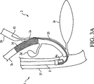
しかしながら、現在利用可能なステント及び導入器の形状は、第1ステントの設置が第2ステントの設置を妨げるようになっている。図3は、ステントを総胆管2aと左右肝管2b、2c内に配置する先行技術の方法に伴う問題を示している。即ち、ステント16を総胆管2aと左肝管2b内に設置すると、その後、右肝管2c内の狭窄に接近できないようになる。つまり、右肝管2c内にステントを設置するのを妨げている。
However, currently available stent and introducer configurations are such that the placement of the first stent prevents the placement of the second stent. FIG. 3 illustrates the problems associated with prior art methods of placing a stent within the common bile duct 2a and left and right
図3Aは、2つのステントを順次設置するときに、先行技術が遭遇する或る問題を示している。つまり、第1ステントが展開されると、第1ステントは、第2ステントを展開するのに用いられる第2導入器20の挿入を妨げる。ステントの順次展開に替わるものが、同時展開である。しかしながら、同時展開は、2つのステント導入器を内視鏡の作業チャネル内に並列配置する必要がある。設置するステントの寸法と、内視鏡の作業チャネルの制限された寸法に依っては、この選択肢は使えない可能性がある。 FIG. 3A illustrates one problem that the prior art encounters when installing two stents sequentially. That is, when the first stent is deployed, the first stent prevents insertion of the second introducer 20 that is used to deploy the second stent. An alternative to sequential stent deployment is simultaneous deployment. However, simultaneous deployment requires two stent introducers to be placed in parallel within the working channel of the endoscope. Depending on the dimensions of the stent to be installed and the limited dimensions of the endoscope working channel, this option may not be available.
従って、先行技術の送出システムに伴う問題を克服する自己拡張式ステント送出システムが必要とされている。具体的には、外科医が分岐部の分枝管腔と主管腔内に第1及び第2ステントを順次設置できる、自己拡張式ステント送出システムが必要とされている。 Accordingly, there is a need for a self-expanding stent delivery system that overcomes the problems associated with prior art delivery systems. Specifically, there is a need for a self-expanding stent delivery system that allows a surgeon to sequentially place first and second stents in the branch lumen and main lumen of the bifurcation.
従って、本発明の目的は、上記欠点の1つ又はそれ以上を解決又は改良する特徴を有する医療用装置、方法及び器具を提供することである。 Accordingly, it is an object of the present invention to provide medical devices, methods and instruments having features that solve or ameliorate one or more of the above disadvantages.
以上の目的は、第1ステントを展開させるのに用いられる第1導入器と、その後第2ステントを展開させるのに用いられる第2導入器を受けるのに使用されるシース又はカテーテルと、を有するステント送出システムを提供することによって達成される。第1導入器とカテーテルは、内視鏡の作業チャネルを通して、例えば互い違いに同時に展開されることができる。第1ステントが展開されると、カテーテルは、第2導入器を目標の生体構造に容易に送出できるようになる。カテーテル又はシースは、引裂可能とすることができる。 The above objective has a first introducer that is used to deploy a first stent and a sheath or catheter that is used to receive a second introducer that is subsequently used to deploy a second stent. This is accomplished by providing a stent delivery system. The first introducer and the catheter can be deployed simultaneously through the working channel of the endoscope, eg, alternately. Once the first stent is deployed, the catheter can easily deliver the second introducer to the target anatomy. The catheter or sheath can be tearable.
別の態様では、第1導入器、カテーテル、及び第2導入器の設置を案内するために、ワイヤーガイドが用いられている。 In another aspect, wire guides are used to guide the placement of the first introducer, the catheter, and the second introducer.
更に別の態様では、以上の目的は、分岐している目標の生体構造の分枝部にステントを設置する方法を提供することによって達成される。本方法は、第1及び第2ワイヤーガイドを、内視鏡の作業チャネル内に配置する段階を含んでいる。第1ワイヤーガイドは、分岐の第1分枝管腔に挿入される。第2ワイヤーガイドは、分岐の第2分枝管腔に挿入される。次いで、第1導入器と引裂可能なカテーテルは、各ワイヤーガイド上を各々の目標の生体構造まで進められる。所定の位置に達すると、第1ステントが展開される。次に、第2導入器が、第2ガイドワイヤー上を導入され、引裂可能なカテーテルを通して、適切な目標の生体構造まで進められる。第2導入器が所定の位置に達すると、第2ステントが展開される。 In yet another aspect, the above objective is accomplished by providing a method of placing a stent on a branch of a target anatomy that is bifurcated. The method includes disposing first and second wire guides in a working channel of an endoscope. The first wire guide is inserted into the branched first branch lumen. The second wire guide is inserted into the branched second branch lumen. The first introducer and tearable catheter are then advanced over each wire guide to the respective target anatomy. When the predetermined position is reached, the first stent is deployed. A second introducer is then introduced over the second guide wire and advanced through the tearable catheter to the appropriate target anatomy. When the second introducer reaches a predetermined position, the second stent is deployed.
本発明の方法は、内視鏡の作業チャネルの内側で、第1導入器の近位部分が引裂可能なカテーテルに隣接して配置され、第1導入器の遠位部分が、引裂可能なカテーテルの遠位側に配置されるように、内視鏡の作業中チャネル内で第1導入器と引裂可能なカテーテルを配置する段階と、第1ステントを、分岐の第1分枝管腔と主管腔内で展開させる段階と、第1導入器を分岐から引き抜く段階と、及び/又は引裂可能なカテーテルを引き裂き、引裂可能なカテーテルを分岐部から引き抜く段階、の何れかを更に含んでいてもよい。 The method of the present invention includes a proximal portion of a first introducer disposed adjacent to a tearable catheter inside a working channel of an endoscope, wherein a distal portion of the first introducer is a tearable catheter. Positioning a first introducer and a tearable catheter within the working channel of the endoscope so as to be disposed distally of the endoscope; a first stent; a branch first branch lumen and a main tube; The method may further include: deploying in the cavity; pulling the first introducer from the bifurcation; and / or tearing the tearable catheter and pulling the tearable catheter from the bifurcation. .
以下、図面を参照してゆくが、各図を通して同様の番号は同じ要素を示しており、図1−2、4は、主管腔、第1分枝管腔、及び第2分枝管腔を有する分岐を示している。具体的には、これらの図面は、胆管系内の分岐を示しており、主管腔は総胆管2aを備えており、第1及び第2分枝管腔はそれぞれ左右の肝管2b、2cを備えている。図1は、狭窄の無い、正常な、即ち健康な胆管系を示している。図2は、分岐の主管腔と両方の分岐管腔内に狭窄3の在る胆管系を示している。図4は、本発明の方法によって、左右の肝管2b、2cそれぞれと総胆管2aに設置されている一対のステントを示している。
Referring now to the drawings, in which like numerals refer to like elements throughout the Figures, FIGS. 1-2, 4 show the main lumen, the first branch lumen, and the second branch lumen. The branch which has is shown. Specifically, these drawings show bifurcations in the bile duct system, the main lumen is provided with the common bile duct 2a, and the first and second branch lumens respectively include the left and right
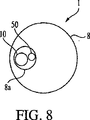
図5−9は、本発明に従って作られたステント送出システム1を示している。ステント送出システム1は、第1ステント16を有する第1導入器10と、第2ステント26を備えた第2導入器20と、引裂可能なカテーテル50を含んでいる。第1導入器10と引裂可能なカテーテル50は、図5、8、9に示すように、内視鏡8の作業チャネル8a内に配置できるようになっている。図7に示すように、引裂可能なカテーテル50は、その内径を通して第2導入器を前進させることのできる内径を有している。ステント送出システム1は、図5に示すように、第1及び第2ワイヤーガイド32、42を含んでいる。
FIGS. 5-9 illustrate a
引裂可能なカテーテル50には、内径と外径がある。引裂可能なカテーテル50の内径は、図7で良く分かるように、第2導入器20を収容できるようになっている。引裂可能なカテーテル50は、適していれば当該技術では既知のどの様な材料でも作ることができ、限定するわけではないが、PTFE、ポリアミド、ポリウレタン、ポリエチレン、ナイロンなどの多層又は単層構造で作られている。代わりに、引裂可能なカテーテル50は、引裂可能な材料、即ち、シースの長さに沿って長手方向に容易に裂くことのできる材料で作ってもよい。限定するわけではないが、例を挙げると、引裂可能な材料は、PEEL−AWAY(登録商標)シース(インディアナ州ブルーミントン、Cook社)に用いられているような分子指向性(非等方性)ポリテトラフルオロエチレン(PTFE)がそうである。随意的に、引裂可能なカテーテル50は、引き裂き易くするため、溝、事前切り目、弱体化領域又は事前切り込み端部を備えている。一般的に、引裂可能なカテーテル50の寸法は、約5Fr.から約9Fr.の範囲にある。これらの寸法は、分かり易くするために提供しているのであり、本発明を限定して解釈される意図はない。当業者には理解頂けるように、引裂可能なカテーテル50の寸法は、その中を通して前進させる第2導入器20の寸法に関係し、これは、またその中に圧縮又は非拡張状態で入っている第2ステント26の寸法に関係する。従って、将来的に利用可能になるかもしれない約5Fr.より小さい引裂可能なカテーテルは、本発明の請求の範囲内にあると考えられる。
The
本発明のステント送出システムの第1及び第2導入器10、20については、ステントを導入し、展開することのできる、あらゆる導入器が考えられる。限定するわけではないが、例を挙げると、胆管ステント展開送出システム、並びに、同時係属中の米国仮特許出願第10/728,589号(代理人整理番号10000/218)に記載されている導入器がそうであり、同出願全体を参考文献として援用する。第1及び第2導入器10、20は、型式と寸法が同じでも、異なっていてもよい。従って、ここに記載の典型的な導入器については、第1導入器10についてのみ述べることとする。
For the first and
図10−15は、限定するわけではないが、導入器10の典型的な実施形態を示している。図10に示す或る典型的な実施形態では、導入器10は、近位端と遠位端を有しており、内側及び外側の同軸管を備えている。外側同軸管は、外側カテーテル又はシース11を形成している。内側同軸管は、シャフト13を形成している。
FIGS. 10-15 illustrate an exemplary embodiment of
シャフト13は、近位端13a、遠位端13b、及びステント保持領域15を有している。随意的に、シャフト13は、ステント保持領域15に取り付けられているプッシャーバンド17、シャフトの遠位端13bに取り付けられている遠位端18、及びワイヤーガイド孔19を含んでいる。シャフト13は、適していれば当該技術で既知のどの様な材料で作ってもよく、限定するわけではないが、ポリエチレンエーテルケトン(PEEK)、ポリテトラフルオロエチレン(PTFE)、ポリアミド、ポリウレタン、ポリエチレン、及びナイロンの多層又は単層構造などで作られ、更に、補強ワイヤ、編みワイヤ、コイル及び/又はフィラメントを含んでいる。シャフト13は、ステンレス鋼、又は当該技術で既知の何れかの他の適した材料のような比較的剛性のある材料で作られている近位部分を備えているのが望ましい。
The
ステント保持領域15は、シャフト13の遠位部分に配置されているのが望ましい。ステント保持領域15は、分岐部で展開されるステント16を保持している。随意的に、ステント16は、自己拡張式ステントである。
Desirably, the
プッシャーバンド17は、ステントを展開させるため外側カテーテル11を近位方向に引き抜く際に、ステントが近位方向に動くのを防ぐ働きをする。プッシャーバンド17は、ステント16の近位側に配置されており、図10−15に示すように、ステント16の近位端がプッシャーバンド17に当接するようになっている。
The
遠位先端18は、導入器10を身体管腔に通して進めるときに、流体が外側カテーテル11に入らないようにする働きする。図10−15に示すように、遠位先端18は、近位端18aと遠位端18bを有している。遠位先端の近位端18aは、遠位外側カテーテルの遠位端14bの直径より小さく、その中に収容されている。随意的に、遠位先端18は、図12に示すように、遠位端18bに向かって直径が小さくなっている。遠位先端18は、適していれば当該技術で既知のどの様な材料で作ってもよく、限定するわけではないが、PEEK、PTFE、ポリアミド、ポリウレタン、ポリエチレン、及びナイロンの多層又は単層構造などで作ることができる。
The
図10と13に示している実施形態では、ワイヤーガイド孔19は、シャフトの遠位端13bからシャフトの近位端13aまで、シャフト13を通って伸張している。この実施形態では、シャフトの近位端13aは、随意的に、図10に示すように、ワイヤーガイド32をシャフト13に対して取り外し可能に固定するためのルアーロック接続具31を含んでいる。図10と13に示す実施形態では、本発明のステント送出システム1は、オーバーザワイヤー式ワイヤーガイドを含んでいる。そのようなワイヤーガイドは、当該技術では既知である。
10 and 13, the
代わりに、ワイヤーガイド孔19は、シャフトの遠位端13bからシャフトの近位端13aまで、シャフト13を通って伸張しているが、ワイヤーガイド32は、導入器10の長さに沿って配置されている穴を通って出ていてもよい。例えば、図14に示すように、ワイヤーガイド32は、遠位先端18の一部分を通って伸張し、遠位先端18の長さに沿って配置されている穴30を通って出ている。この実施形態では、ワイヤーガイド32は、遠位先端18を通って伸張し、ステント16を通ること無く、導入器10を出ている。例えば、ワイヤーガイド32は、遠位先端18を通って近位方向に、約1cmの距離だけ伸張すてもよい。
Instead, the
図15に示す別の実施形態では、ワイヤーガイド孔19は、シャフト13の長さを通って伸張しているが、ワイヤーガイド32は、シャフト13の一部分を通って伸張し、外側カテーテル11の長さに沿って配置されている穴30を通って外に出ている。この実施形態では、ワイヤーガイド32は、遠位先端18を通り、シャフト13の一部分を通り、導入器10を出るまでステント16を通過して伸張している。例えば、ワイヤーガイド32は、遠位先端18を通り、ステント保持領域15を約20cmの距離だけ通って伸張していてもよい。
In another embodiment shown in FIG. 15, the
更に別の代替実施形態では、ワイヤーガイド孔19は、シャフト13の一部分を通って伸張し、導入器10の長さに沿って配置されている穴30を通って外に出ている。導入器10の長さに沿って何れかの位置に配置されている穴30の数は、幾つでもよい。更に、ワイヤーガイド孔19は、チャネル又は割れ目を備えていてもよい。
In yet another alternative embodiment, the
穴30は、本発明のステント送出システムに、迅速交換機能を提供する。具体的には、ワイヤーガイド32を、ワイヤーガイド孔19の遠位部分だけを通して伸張させることによって、送出システムを、ワイヤーガイド32がワイヤーガイド孔19の全長を通って伸張している場合に必要な長さよりも実質的に短い長さを有するワイヤーガイド32から、取り外すことができる。
図10に示すように、シース又は外側カテーテル11は、近位端11aと遠位端11bを有している。少なくとも外側カテーテル11の遠位部分は、シャフト13のステント保持領域15に取り付けられているステント16が見えるように、何らかの光学的に透明又は像を取得可能な材料で作られているのが望ましい。外側カテーテル11は、更に、近位端12aと遠位端12bをそれぞれ有する近位外側カテーテル12と、近位端14aと遠位端14bをそれぞれ有する遠位外側カテーテル14を含んでいる。近位外側カテーテル12の遠位端12bは、遠位外側カテーテル14の近位端14aに取り付けられ、外側カテーテル11を形成している。近位外側カテーテル12の遠位端12bは、限定するわけではないが、熱溶解、接着剤接着、化学的接着又は機械的嵌め合いを含む当該技術では既知のどの様な方法で、遠位外側カテーテル14の近位端14aに取り付けてもよい。或いは、近位外側カテーテル12と遠位外側カテーテル14は、1つのカテーテル又はシースで形成してもよい。約0.077インチから約0.78インチの圧縮された直径を有する第1ステント16を配置するために、第1導入器の近位外径は約5Fr.から約6Fr.であり、第1導入器の遠位外径は約6Fr.から約6.5Fr.である。これらの寸法は、例証を目的に呈示しているのであり、本発明を限定する意図は無いものと理解頂きたい。当業者には理解頂けるように、ステントを設置するのに必要な導入器の寸法は、設置するステントの寸法に関係しており、具体的には、ステントの圧縮された状態の寸法に関係している。従って、将来は利用できるようになるであろう約0.078インチより小さな圧縮された形状を有するステントを設置するのに用いられる約6Fr.より小さな遠位外径を有する導入器も、本発明の請求の範囲内にあると考えられる。
As shown in FIG. 10, the sheath or outer catheter 11 has a proximal end 11a and a distal end 11b. At least the distal portion of the outer catheter 11 is preferably made of some optically transparent or imageable material so that the
第1導入器10と引裂可能なカテーテル50は、内視鏡8の作業チャネル8a内で互いに隣接して配置できる寸法に作られている。具体的には、第1導入器10の外径(即ち、近位外径か遠位外径の何れか)と引裂可能なカテーテルの外径の合計は、内視鏡8の作業チャネル8aの内径より小さい。
The
図9に示す実施形態では、第1導入器10と引裂可能なカテーテル50は、内視鏡8の作業チャネル8a内に、互い違いに、互いに隣接して配置されている。つまり、導入器は、大きな直径の部分(ステント保持領域)と小さな直径の部分(近位外側カテーテル)を有している。カテーテル50は、第1導入器10の大径のステント保持領域に重ならないように、ずらして配置されている。図9で分かるように、第1導入器の近位外径と引裂可能なカテーテル50の外径の合計は、内視鏡8の作業チャネル8aの内径より小さい。
In the embodiment shown in FIG. 9, the
本発明のステント送出システム1の更に別の代替実施形態では、第1導入器10と引裂可能なカテーテル50は、内視鏡8の作業チャネル8a内に少なくとも1つのワイヤーガイド32、42を収容できる大きさに作られている。この実施形態では、第1導入器の近位外径と、引裂可能なカテーテルの外径と、第1及び第2ワイヤーガイド32、42の内の少なくとも1つとの合計は、内視鏡8の作業チャネル8aの内径より小さい。
In yet another alternative embodiment of the
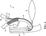
本発明のステント送出システム1は、以下のように、第1及び第2ステント16、26を、主管腔2aと第1及び第2分枝管腔2b、2c内に狭窄3を有する分岐部に設置するのに用いられる。内視鏡を使って、第1ワイヤーガイドの遠位端は、分岐部の第1分枝管腔の中へ進められ、第2ワイヤーガイドの遠位端は、分岐部の第2分枝管腔の中へ進められる。第1導入器10と引裂可能なカテーテル50は、ガイドワイヤー上を内視鏡8の作業チャネル8a内へと挿入される。その結果、図5に示すように、第1導入器10は分岐部の第1分枝内に配置され、引裂可能なカテーテル50は分岐部の第2分枝管腔内に配置される。第1導入器10と引裂可能なカテーテル50は、順次、又は同時に配置される。第1導入器10は、第1ステント16が、少なくとも部分的には、分岐部の第1分枝が狭まって閉塞している中に整列するように配置される。整列すると、図6に示すように、第1ステントは分岐部の第1分枝内で展開され、第1導入器は引き出される。第1導入器10を取り除いた後、第2導入器20は、内視鏡8の作業チャネル8aを通し、第2ワイヤーガイド42上を、引裂可能なカテーテル50を通して進められる。図7は、第2導入器20が、展開した第1ステント16に絡まるか又は遮られることがないようにするシールドとして、引裂可能なカテーテル50が作用することを示している。図7は、更に、第2導入器20を、引裂可能なカテーテル50を通して第2分枝管腔26の中へと進める際に、引裂可能なカテーテル50が裂け、又は剥がれることを示している。第2導入器20が第2分枝管腔2b内に配置されると、引裂可能なカテーテル50は取り外され、第2ステント26は第2分枝管腔2bと主管腔2a内で展開される。その結果の構成を、図4に示している。
In the
上記図面と開示は、例証を目的としており、網羅することを意図してはいない。この説明は、当業者に多くの変更及び代替案を想起させるであろう。そのような全ての変更及び代替案は、特許請求の範囲内に包含されるものとする。当該技術に精通している当業者には理解頂けるように、ここに記載している特定の実施形態に対する他の等価物も、特許請求の範囲に包含される。例えば、本発明は、例証を目的に胆管系について説明している。本発明の原理を患者の身体内の他の分岐管腔又は脈管に適用することは、限定するわけではないが、例えば、膵臓系の様な消化管内の領域、並びに他の脈管系の様な消化管以外の領域を含め、当業者の想定の範囲内にあり、特許請求の範囲に包含されるものとする。 The above drawings and disclosure are for illustrative purposes and are not intended to be exhaustive. This description will remind those skilled in the art of many variations and alternatives. All such modifications and alternatives are intended to be included within the scope of the claims. Other equivalents to the specific embodiments described herein are also within the scope of the claims, as will be appreciated by those skilled in the art. For example, the present invention describes the bile duct system for purposes of illustration. Application of the principles of the present invention to other branch lumens or vessels within the patient's body includes, but is not limited to, for example, regions within the gastrointestinal tract such as the pancreatic system, as well as other vascular systems. Such areas other than the gastrointestinal tract are within the scope of those skilled in the art and are intended to be encompassed by the claims.
Claims (15)
近位端と、遠位端と、それらの間のステント搬送部分とを有する管状体を備えている第1導入器と、
近位端と、遠位端と、それらの間のステント搬送部分とを有する管状体を備えている第2導入器と、
前記第2導入器が、その長手方向で前進するときに、その遠位端を受け入れて該第2導入器の前進を前記長手方向で案内する長手方向に延びる内周面を画定し、第2導入器の前進にともなって裂けるようになされている壁を有するカテーテルと、を備えており、
前記第1導入器と前記カテーテルは、内視鏡の作業チャネル内で隣接して配置されるようになっている、キット。In a kit for delivering the first and second stents to the branched target anatomy,
A first introducer comprising a tubular body having a proximal end, a distal end, and a stent delivery portion therebetween;
A second introducer comprising a tubular body having a proximal end, a distal end, and a stent delivery portion therebetween;
Defining a longitudinally extending inner circumferential surface that receives a distal end thereof and guides advancement of the second introducer in the longitudinal direction when the second introducer is advanced in the longitudinal direction; A catheter having a wall adapted to tear as the introducer advances ,
The kit, wherein the first introducer and the catheter are arranged adjacent to each other in a working channel of an endoscope.
前記第2導入器の前記ステント搬送部分の中に配置されている第2ステントと、を更に備えている、請求項1に記載のキット。A first stent disposed in the stent delivery portion of the first introducer;
The kit of claim 1, further comprising a second stent disposed in the stent delivery portion of the second introducer.
前記第2導入器をうけいれるように構成されている第2ワイヤーガイドと、を更に備えている、請求項1又は2に記載のキット。A first wire guide configured to receive the first introducer;
Wherein the second wire guide is configured to receive the second introducer further comprises a kit according to claim 1 or 2.
前記遠位端と、前記ステント搬送部分の近位側に配置されているポートとの間を伸張している経路を更に備えており、前記ポートはワイヤーガイドを受け入れるようになっている、請求項1又は2に記載のキット。The first introducer includes:
The method further comprises a path extending between the distal end and a port disposed proximally of the stent delivery portion, the port adapted to receive a wire guide. The kit according to 1 or 2.
前記遠位端と、前記ステント搬送部分の近位側に配置されているポートとの間を伸張している経路を更に備えており、前記ポートはワイヤーガイドを受け入れるようになっている、請求項1又は2に記載のキット。The second introducer is
The method further comprises a path extending between the distal end and a port disposed proximally of the stent delivery portion, the port adapted to receive a wire guide. The kit according to 1 or 2.
前記遠位端と、前記ステント搬送部分の遠位側に配置されているポートとの間を伸張している経路を更に備えており、前記ポートはワイヤーガイドを受け入れるようになっている、請求項1又は2に記載のキット。The first introducer includes:
The method further comprises a path extending between the distal end and a port disposed distally of the stent delivery portion, the port adapted to receive a wire guide. The kit according to 1 or 2.
前記遠位端と、前記ステント搬送部分の遠位側に配置されているポートとの間を伸張している経路を更に備えており、前記ポートはワイヤーガイドを受け入れるようになっている、請求項1又は2に記載のキット。The second introducer is
The method further comprises a path extending between the distal end and a port disposed distally of the stent delivery portion, the port adapted to receive a wire guide. The kit according to 1 or 2.
Applications Claiming Priority (3)
| Application Number | Priority Date | Filing Date | Title |
|---|---|---|---|
| US55872104P | 2004-03-31 | 2004-03-31 | |
| US60/558,721 | 2004-03-31 | ||
| PCT/US2005/010904 WO2005096994A1 (en) | 2004-03-31 | 2005-03-31 | Stent introducer system |
Publications (3)
| Publication Number | Publication Date |
|---|---|
| JP2007531599A JP2007531599A (en) | 2007-11-08 |
| JP2007531599A5 JP2007531599A5 (en) | 2008-05-15 |
| JP4714736B2 true JP4714736B2 (en) | 2011-06-29 |
Family
ID=34964750
Family Applications (1)
| Application Number | Title | Priority Date | Filing Date |
|---|---|---|---|
| JP2007506559A Expired - Fee Related JP4714736B2 (en) | 2004-03-31 | 2005-03-31 | Stent introducer system |
Country Status (6)
| Country | Link |
|---|---|
| US (2) | US20050273150A1 (en) |
| EP (1) | EP1732470B1 (en) |
| JP (1) | JP4714736B2 (en) |
| AT (1) | ATE468830T1 (en) |
| DE (1) | DE602005021473D1 (en) |
| WO (1) | WO2005096994A1 (en) |
Families Citing this family (18)
| Publication number | Priority date | Publication date | Assignee | Title |
|---|---|---|---|---|
| US8034100B2 (en) | 1999-03-11 | 2011-10-11 | Endologix, Inc. | Graft deployment system |
| US6261316B1 (en) | 1999-03-11 | 2001-07-17 | Endologix, Inc. | Single puncture bifurcation graft deployment system |
| AU2008286878A1 (en) * | 2007-08-15 | 2009-02-19 | Wilson-Cook Medical Inc. | Deployment system for soft stents |
| WO2009105699A1 (en) | 2008-02-22 | 2009-08-27 | Endologix, Inc. | Design and method of placement of a graft or graft system |
| US8236040B2 (en) | 2008-04-11 | 2012-08-07 | Endologix, Inc. | Bifurcated graft deployment systems and methods |
| EP2293838B1 (en) | 2008-07-01 | 2012-08-08 | Endologix, Inc. | Catheter system |
| EP2429452B1 (en) | 2009-04-28 | 2020-01-15 | Endologix, Inc. | Endoluminal prosthesis system |
| EP2635241B1 (en) | 2010-11-02 | 2019-02-20 | Endologix, Inc. | Apparatus for placement of a graft or graft system |
| WO2012118901A1 (en) | 2011-03-01 | 2012-09-07 | Endologix, Inc. | Catheter system and methods of using same |
| US9113879B2 (en) | 2011-12-15 | 2015-08-25 | Ethicon Endo-Surgery, Inc. | Devices and methods for endoluminal plication |
| US9113868B2 (en) | 2011-12-15 | 2015-08-25 | Ethicon Endo-Surgery, Inc. | Devices and methods for endoluminal plication |
| US8992547B2 (en) | 2012-03-21 | 2015-03-31 | Ethicon Endo-Surgery, Inc. | Methods and devices for creating tissue plications |
| WO2014144809A1 (en) * | 2013-03-15 | 2014-09-18 | Altura Medical, Inc. | Endograft device delivery systems and associated methods |
| WO2017004265A1 (en) | 2015-06-30 | 2017-01-05 | Endologix, Inc. | Locking assembly for coupling guidewire to delivery system |
| GB201522683D0 (en) * | 2015-12-22 | 2016-02-03 | Endogi Ltd | Deployment of multiple biliary stents |
| JPWO2020013209A1 (en) * | 2018-07-13 | 2021-07-15 | 隆夫 糸井 | Stent |
| CN109620492A (en) * | 2019-01-31 | 2019-04-16 | 郑州大学第附属医院 | Through duodenofiberscope Retrograde device under Y type biliary tract rack scope |
| US11744694B2 (en) | 2020-01-01 | 2023-09-05 | Endo Gi Medical Ltd. | Methods and assemblies for deploying biliary stents |
Citations (2)
| Publication number | Priority date | Publication date | Assignee | Title |
|---|---|---|---|---|
| JPH07275369A (en) * | 1994-04-15 | 1995-10-24 | N & M:Kk | Assembly for internal fistula strictured part in bile duct |
| JP2001504017A (en) * | 1996-11-15 | 2001-03-27 | クック インコーポレーティッド. | Separable sleeve, stent deployment device |
Family Cites Families (164)
| Publication number | Priority date | Publication date | Assignee | Title |
|---|---|---|---|---|
| US3485234A (en) | 1966-04-13 | 1969-12-23 | Cordis Corp | Tubular products and method of making same |
| US3585707A (en) * | 1966-04-13 | 1971-06-22 | Cordis Corp | Method of making tubular products |
| US3612058A (en) | 1968-04-17 | 1971-10-12 | Electro Catheter Corp | Catheter stylets |
| US3657744A (en) * | 1970-05-08 | 1972-04-25 | Univ Minnesota | Method for fixing prosthetic implants in a living body |
| US4056854A (en) | 1976-09-28 | 1977-11-08 | The United States Of America As Represented By The Department Of Health, Education And Welfare | Aortic heart valve catheter |
| US4140126A (en) * | 1977-02-18 | 1979-02-20 | Choudhury M Hasan | Method for performing aneurysm repair |
| US4306562A (en) | 1978-12-01 | 1981-12-22 | Cook, Inc. | Tear apart cannula |
| US4516972A (en) * | 1982-01-28 | 1985-05-14 | Advanced Cardiovascular Systems, Inc. | Guiding catheter and method of manufacture |
| SE445884B (en) * | 1982-04-30 | 1986-07-28 | Medinvent Sa | DEVICE FOR IMPLANTATION OF A RODFORM PROTECTION |
| US4503569A (en) * | 1983-03-03 | 1985-03-12 | Dotter Charles T | Transluminally placed expandable graft prosthesis |
| CA1232814A (en) * | 1983-09-16 | 1988-02-16 | Hidetoshi Sakamoto | Guide wire for catheter |
| US4581025A (en) * | 1983-11-14 | 1986-04-08 | Cook Incorporated | Sheath |
| US5104399A (en) * | 1986-12-10 | 1992-04-14 | Endovascular Technologies, Inc. | Artificial graft and implantation method |
| US5693083A (en) * | 1983-12-09 | 1997-12-02 | Endovascular Technologies, Inc. | Thoracic graft and delivery catheter |
| US5275622A (en) * | 1983-12-09 | 1994-01-04 | Harrison Medical Technologies, Inc. | Endovascular grafting apparatus, system and method and devices for use therewith |
| JPS60126170A (en) * | 1983-12-14 | 1985-07-05 | テルモ株式会社 | Catheter and its production |
| US4562596A (en) * | 1984-04-25 | 1986-01-07 | Elliot Kornberg | Aortic graft, device and method for performing an intraluminal abdominal aortic aneurysm repair |
| US4580568A (en) * | 1984-10-01 | 1986-04-08 | Cook, Incorporated | Percutaneous endovascular stent and method for insertion thereof |
| US4665771A (en) * | 1984-10-15 | 1987-05-19 | Mitchell Frank R | Hypocyclic drive |
| IT1186142B (en) * | 1984-12-05 | 1987-11-18 | Medinvent Sa | TRANSLUMINAL IMPLANTATION DEVICE |
| US4705511A (en) | 1985-05-13 | 1987-11-10 | Bipore, Inc. | Introducer sheath assembly |
| US4733665C2 (en) * | 1985-11-07 | 2002-01-29 | Expandable Grafts Partnership | Expandable intraluminal graft and method and apparatus for implanting an expandable intraluminal graft |
| US4665918A (en) * | 1986-01-06 | 1987-05-19 | Garza Gilbert A | Prosthesis system and method |
| DE3786721D1 (en) | 1986-02-24 | 1993-09-02 | Fischell Robert | DEVICE FOR DETECTING BLOOD VESSELS AND SYSTEM FOR ITS INTRODUCTION. |
| US4676229A (en) * | 1986-04-09 | 1987-06-30 | Welch Allyn, Inc. | Biopsy channel for an endoscope |
| US4665905A (en) * | 1986-06-09 | 1987-05-19 | Brown Charles S | Dynamic elbow and knee extension brace |
| SE454482B (en) | 1986-09-30 | 1988-05-09 | Medinvent Sa | DEVICE FOR IMPLANTATION |
| US4793348A (en) | 1986-11-15 | 1988-12-27 | Palmaz Julio C | Balloon expandable vena cava filter to prevent migration of lower extremity venous clots into the pulmonary circulation |
| JPS63238872A (en) * | 1987-03-25 | 1988-10-04 | テルモ株式会社 | Instrument for securing inner diameter of cavity of tubular organ and catheter equipped therewith |
| US4817613A (en) * | 1987-07-13 | 1989-04-04 | Devices For Vascular Intervention, Inc. | Guiding catheter |
| JPS6446477A (en) * | 1987-08-13 | 1989-02-20 | Terumo Corp | Catheter |
| US5201901A (en) * | 1987-10-08 | 1993-04-13 | Terumo Kabushiki Kaisha | Expansion unit and apparatus for expanding tubular organ lumen |
| FR2624747A1 (en) * | 1987-12-18 | 1989-06-23 | Delsanti Gerard | REMOVABLE ENDO-ARTERIAL DEVICES FOR REPAIRING ARTERIAL WALL DECOLLEMENTS |
| US4830003A (en) * | 1988-06-17 | 1989-05-16 | Wolff Rodney G | Compressive stent and delivery system |
| US4898591A (en) * | 1988-08-09 | 1990-02-06 | Mallinckrodt, Inc. | Nylon-PEBA copolymer catheter |
| US5019090A (en) * | 1988-09-01 | 1991-05-28 | Corvita Corporation | Radially expandable endoprosthesis and the like |
| SE8803444D0 (en) * | 1988-09-28 | 1988-09-28 | Medinvent Sa | A DEVICE FOR TRANSLUMINAL IMPLANTATION OR EXTRACTION |
| US4994066A (en) * | 1988-10-07 | 1991-02-19 | Voss Gene A | Prostatic stent |
| US4950227A (en) * | 1988-11-07 | 1990-08-21 | Boston Scientific Corporation | Stent delivery system |
| US4985022A (en) | 1988-11-23 | 1991-01-15 | Med Institute, Inc. | Catheter having durable and flexible segments |
| US4875468A (en) | 1988-12-23 | 1989-10-24 | Welch Allyn, Inc. | Elastomer-ePTFE biopsy channel |
| US4969891A (en) | 1989-03-06 | 1990-11-13 | Gewertz Bruce L | Removable vascular filter |
| US5045072A (en) | 1989-06-13 | 1991-09-03 | Cordis Corporation | Catheter having highly radiopaque, flexible tip |
| EP0408245B1 (en) * | 1989-07-13 | 1994-03-02 | American Medical Systems, Inc. | Stent placement instrument |
| US5217440A (en) * | 1989-10-06 | 1993-06-08 | C. R. Bard, Inc. | Multilaminate coiled film catheter construction |
| US5019057A (en) * | 1989-10-23 | 1991-05-28 | Cordis Corporation | Catheter having reinforcing strands |
| US5478320A (en) * | 1989-11-29 | 1995-12-26 | Cordis Corporation | Puncture resistant balloon catheter and method of manufacturing |
| US5057092A (en) | 1990-04-04 | 1991-10-15 | Webster Wilton W Jr | Braided catheter with low modulus warp |
| US5104388A (en) * | 1990-05-08 | 1992-04-14 | Fbk International Corporation | Membrane splittable tubing |
| US5064435A (en) | 1990-06-28 | 1991-11-12 | Schneider (Usa) Inc. | Self-expanding prosthesis having stable axial length |
| US5279596A (en) * | 1990-07-27 | 1994-01-18 | Cordis Corporation | Intravascular catheter with kink resistant tip |
| US5222971A (en) * | 1990-10-09 | 1993-06-29 | Scimed Life Systems, Inc. | Temporary stent and methods for use and manufacture |
| US5190520A (en) * | 1990-10-10 | 1993-03-02 | Strato Medical Corporation | Reinforced multiple lumen catheter |
| AU8850391A (en) * | 1990-10-18 | 1992-05-20 | Ho Young Song | Self-expanding endovascular stent |
| US5160341A (en) | 1990-11-08 | 1992-11-03 | Advanced Surgical Intervention, Inc. | Resorbable urethral stent and apparatus for its insertion |
| US5254107A (en) | 1991-03-06 | 1993-10-19 | Cordis Corporation | Catheter having extended braid reinforced transitional tip |
| CA2202800A1 (en) * | 1991-04-11 | 1992-10-12 | Alec A. Piplani | Endovascular graft having bifurcation and apparatus and method for deploying the same |
| US5195969A (en) | 1991-04-26 | 1993-03-23 | Boston Scientific Corporation | Co-extruded medical balloons and catheter using such balloons |
| US5197978B1 (en) * | 1991-04-26 | 1996-05-28 | Advanced Coronary Tech | Removable heat-recoverable tissue supporting device |
| US5221270A (en) * | 1991-06-28 | 1993-06-22 | Cook Incorporated | Soft tip guiding catheter |
| US5306252A (en) * | 1991-07-18 | 1994-04-26 | Kabushiki Kaisha Kobe Seiko Sho | Catheter guide wire and catheter |
| US5151105A (en) | 1991-10-07 | 1992-09-29 | Kwan Gett Clifford | Collapsible vessel sleeve implant |
| US5387235A (en) * | 1991-10-25 | 1995-02-07 | Cook Incorporated | Expandable transluminal graft prosthesis for repair of aneurysm |
| AU669338B2 (en) | 1991-10-25 | 1996-06-06 | Cook Incorporated | Expandable transluminal graft prosthesis for repair of aneurysm and method for implanting |
| CA2380683C (en) * | 1991-10-28 | 2006-08-08 | Advanced Cardiovascular Systems, Inc. | Expandable stents and method for making same |
| US5290310A (en) * | 1991-10-30 | 1994-03-01 | Howmedica, Inc. | Hemostatic implant introducer |
| DE4200255A1 (en) * | 1992-01-08 | 1993-07-15 | Sueddeutsche Feinmechanik | SPLIT CANNULA AND METHOD FOR PRODUCING SUCH A |
| US5316023A (en) | 1992-01-08 | 1994-05-31 | Expandable Grafts Partnership | Method for bilateral intra-aortic bypass |
| US5221372A (en) * | 1992-02-13 | 1993-06-22 | Northwestern University | Fracture-tough, high hardness stainless steel and method of making same |
| US5201757A (en) * | 1992-04-03 | 1993-04-13 | Schneider (Usa) Inc. | Medial region deployment of radially self-expanding stents |
| FR2689388B1 (en) | 1992-04-07 | 1999-07-16 | Celsa Lg | PERFECTIONALLY RESORBABLE BLOOD FILTER. |
| US5354308A (en) | 1992-05-01 | 1994-10-11 | Beth Israel Hospital Association | Metal wire stent |
| US5599300A (en) * | 1992-05-11 | 1997-02-04 | Arrow Precision Products, Inc. | Method for electrosurgically obtaining access to the biliary tree with an adjustably positionable needle-knife |
| US5314462A (en) * | 1992-05-27 | 1994-05-24 | Cardiac Pacemakers, Inc. | Positive fixation device |
| US5290295A (en) * | 1992-07-15 | 1994-03-01 | Querals & Fine, Inc. | Insertion tool for an intraluminal graft procedure |
| US5707376A (en) * | 1992-08-06 | 1998-01-13 | William Cook Europe A/S | Stent introducer and method of use |
| US5250071A (en) | 1992-09-22 | 1993-10-05 | Target Therapeutics, Inc. | Detachable embolic coil assembly using interlocking clasps and method of use |
| ES2089342T3 (en) * | 1992-10-31 | 1996-10-01 | Schneider Europ Ag | DISPOSITION OF INTRODUCTION OF A SELF-EXPANDING ENDOPROTESIS. |
| CA2149887A1 (en) | 1992-12-30 | 1994-07-21 | Steven J. Healy | Apparatus for deploying body implantable stents |
| US5318586A (en) * | 1993-01-19 | 1994-06-07 | Erkan Ereren | Laparoscopic and thoracoscopic expandable instruments |
| US5474563A (en) | 1993-03-25 | 1995-12-12 | Myler; Richard | Cardiovascular stent and retrieval apparatus |
| WO1994023786A1 (en) * | 1993-04-13 | 1994-10-27 | Boston Scientific Corporation | Prosthesis delivery system |
| US5480423A (en) * | 1993-05-20 | 1996-01-02 | Boston Scientific Corporation | Prosthesis delivery |
| US5391172A (en) * | 1993-05-24 | 1995-02-21 | Advanced Cardiovascular Systems, Inc. | Stent delivery system with coaxial catheter handle |
| IL105828A (en) | 1993-05-28 | 1999-06-20 | Medinol Ltd | Medical stent |
| US5464449A (en) | 1993-07-08 | 1995-11-07 | Thomas J. Fogarty | Internal graft prosthesis and delivery system |
| DE4428914C2 (en) | 1993-08-18 | 2000-09-28 | Scimed Life Systems Inc | Thin-walled multi-layer catheter |
| US5639278A (en) * | 1993-10-21 | 1997-06-17 | Corvita Corporation | Expandable supportive bifurcated endoluminal grafts |
| US5571135A (en) | 1993-10-22 | 1996-11-05 | Scimed Life Systems Inc. | Stent delivery apparatus and method |
| US5456695A (en) | 1993-10-25 | 1995-10-10 | United States Surgical Corporation | Multi-tool surgical apparatus |
| EP0657147B1 (en) * | 1993-11-04 | 1999-08-04 | C.R. Bard, Inc. | Non-migrating vascular prosthesis |
| JPH07178176A (en) | 1993-12-24 | 1995-07-18 | Terumo Corp | Catheter |
| JP2703510B2 (en) * | 1993-12-28 | 1998-01-26 | アドヴァンスド カーディオヴァスキュラー システムズ インコーポレーテッド | Expandable stent and method of manufacturing the same |
| US5538510A (en) * | 1994-01-31 | 1996-07-23 | Cordis Corporation | Catheter having coextruded tubing |
| US5417708A (en) * | 1994-03-09 | 1995-05-23 | Cook Incorporated | Intravascular treatment system and percutaneous release mechanism therefor |
| US5449373A (en) | 1994-03-17 | 1995-09-12 | Medinol Ltd. | Articulated stent |
| US5415664A (en) * | 1994-03-30 | 1995-05-16 | Corvita Corporation | Method and apparatus for introducing a stent or a stent-graft |
| US5498240A (en) * | 1994-05-27 | 1996-03-12 | Advanced Cardiovascular Systems, Inc. | Intravascular catheter with a replaceable shaft section |
| US5683451A (en) * | 1994-06-08 | 1997-11-04 | Cardiovascular Concepts, Inc. | Apparatus and methods for deployment release of intraluminal prostheses |
| ATE240694T1 (en) * | 1994-06-13 | 2003-06-15 | Endomed Inc | EXPANDABLE ENDOVASCULAR TRANSPLANT AND METHOD FOR PRODUCING SAME |
| US5653743A (en) * | 1994-09-09 | 1997-08-05 | Martin; Eric C. | Hypogastric artery bifurcation graft and method of implantation |
| AU708360B2 (en) * | 1994-09-15 | 1999-08-05 | C.R. Bard Inc. | Hooked endoprosthesis |
| US5702419A (en) | 1994-09-21 | 1997-12-30 | Wake Forest University | Expandable, intraluminal stents |
| EP0788332B1 (en) | 1994-10-27 | 2000-11-08 | Boston Scientific Limited | Stent delivery device |
| AU4242996A (en) * | 1994-11-23 | 1996-06-17 | Navarre Biomedical, Ltd. | Flexible catheter |
| US5591197A (en) * | 1995-03-14 | 1997-01-07 | Advanced Cardiovascular Systems, Inc. | Expandable stent forming projecting barbs and method for deploying |
| US5647857A (en) * | 1995-03-16 | 1997-07-15 | Endotex Interventional Systems, Inc. | Protective intraluminal sheath |
| US5605530A (en) * | 1995-03-23 | 1997-02-25 | Fischell; Robert E. | System for safe implantation of radioisotope stents |
| US5571168A (en) | 1995-04-05 | 1996-11-05 | Scimed Lifesystems Inc | Pull back stent delivery system |
| WO1996032078A1 (en) * | 1995-04-14 | 1996-10-17 | Schneider (Usa) Inc. | Rolling membrane stent delivery device |
| US5534007A (en) * | 1995-05-18 | 1996-07-09 | Scimed Life Systems, Inc. | Stent deployment catheter with collapsible sheath |
| JPH10503411A (en) | 1995-05-25 | 1998-03-31 | メドトロニック・インコーポレーテッド | Stent assembly and method of using the same |
| US5700269A (en) | 1995-06-06 | 1997-12-23 | Corvita Corporation | Endoluminal prosthesis deployment device for use with prostheses of variable length and having retraction ability |
| US5863366A (en) * | 1995-06-07 | 1999-01-26 | Heartport, Inc. | Method of manufacture of a cannula for a medical device |
| US5601600A (en) * | 1995-09-08 | 1997-02-11 | Conceptus, Inc. | Endoluminal coil delivery system having a mechanical release mechanism |
| US5702418A (en) | 1995-09-12 | 1997-12-30 | Boston Scientific Corporation | Stent delivery system |
| US6099558A (en) * | 1995-10-10 | 2000-08-08 | Edwards Lifesciences Corp. | Intraluminal grafting of a bifuricated artery |
| US5669924A (en) | 1995-10-26 | 1997-09-23 | Shaknovich; Alexander | Y-shuttle stent assembly for bifurcating vessels and method of using the same |
| US5628788A (en) * | 1995-11-07 | 1997-05-13 | Corvita Corporation | Self-expanding endoluminal stent-graft |
| DE69508592T2 (en) * | 1995-11-14 | 1999-09-16 | Schneider Europ Gmbh | Stent implantation device |
| US5665103A (en) | 1996-03-07 | 1997-09-09 | Scimed Life Systems, Inc. | Stent locating device |
| US8728143B2 (en) * | 1996-06-06 | 2014-05-20 | Biosensors International Group, Ltd. | Endoprosthesis deployment system for treating vascular bifurcations |
| US5697971A (en) | 1996-06-11 | 1997-12-16 | Fischell; Robert E. | Multi-cell stent with cells having differing characteristics |
| US5776140A (en) * | 1996-07-16 | 1998-07-07 | Cordis Corporation | Stent delivery system |
| US5755781A (en) * | 1996-08-06 | 1998-05-26 | Iowa-India Investments Company Limited | Embodiments of multiple interconnected stents |
| US5800517A (en) | 1996-08-19 | 1998-09-01 | Scimed Life Systems, Inc. | Stent delivery system with storage sleeve |
| US5968068A (en) * | 1996-09-12 | 1999-10-19 | Baxter International Inc. | Endovascular delivery system |
| US5772669A (en) * | 1996-09-27 | 1998-06-30 | Scimed Life Systems, Inc. | Stent deployment catheter with retractable sheath |
| US6027508A (en) * | 1996-10-03 | 2000-02-22 | Scimed Life Systems, Inc. | Stent retrieval device |
| US6596020B2 (en) * | 1996-11-04 | 2003-07-22 | Advanced Stent Technologies, Inc. | Method of delivering a stent with a side opening |
| US5843090A (en) | 1996-11-05 | 1998-12-01 | Schneider (Usa) Inc. | Stent delivery device |
| US6395017B1 (en) * | 1996-11-15 | 2002-05-28 | C. R. Bard, Inc. | Endoprosthesis delivery catheter with sequential stage control |
| US5968052A (en) * | 1996-11-27 | 1999-10-19 | Scimed Life Systems Inc. | Pull back stent delivery system with pistol grip retraction handle |
| US5720735A (en) * | 1997-02-12 | 1998-02-24 | Dorros; Gerald | Bifurcated endovascular catheter |
| US5735859A (en) * | 1997-02-14 | 1998-04-07 | Cathco, Inc. | Distally attachable and releasable sheath for a stent delivery system |
| US5792144A (en) | 1997-03-31 | 1998-08-11 | Cathco, Inc. | Stent delivery catheter system |
| US6165195A (en) * | 1997-08-13 | 2000-12-26 | Advanced Cardiovascylar Systems, Inc. | Stent and catheter assembly and method for treating bifurcations |
| EP0951310B1 (en) | 1997-11-07 | 2005-05-18 | Ave Connaught | Balloon catheter for repairing bifurcated vessels |
| US5938697A (en) | 1998-03-04 | 1999-08-17 | Scimed Life Systems, Inc. | Stent having variable properties |
| US6099497A (en) * | 1998-03-05 | 2000-08-08 | Scimed Life Systems, Inc. | Dilatation and stent delivery system for bifurcation lesions |
| US6425898B1 (en) * | 1998-03-13 | 2002-07-30 | Cordis Corporation | Delivery apparatus for a self-expanding stent |
| US6019778A (en) * | 1998-03-13 | 2000-02-01 | Cordis Corporation | Delivery apparatus for a self-expanding stent |
| US6520983B1 (en) * | 1998-03-31 | 2003-02-18 | Scimed Life Systems, Inc. | Stent delivery system |
| US6033413A (en) * | 1998-04-20 | 2000-03-07 | Endocare, Inc. | Stent delivery system |
| US6146389A (en) | 1998-04-23 | 2000-11-14 | Boston Scientific Corporation | Stent deployment device and method for deploying a stent |
| US7022131B1 (en) * | 1998-05-29 | 2006-04-04 | By-Pass Inc. | Methods and devices for vascular surgery |
| US6117140A (en) * | 1998-06-26 | 2000-09-12 | Scimed Life Systems, Inc. | Stent delivery device |
| US6544278B1 (en) * | 1998-11-06 | 2003-04-08 | Scimed Life Systems, Inc. | Rolling membrane stent delivery system |
| US6254609B1 (en) * | 1999-01-11 | 2001-07-03 | Scimed Life Systems, Inc. | Self-expanding stent delivery system with two sheaths |
| EP1152711B1 (en) * | 1999-01-27 | 2005-07-06 | Boston Scientific Limited | Bifurcation stent delivery system |
| US6379365B1 (en) * | 1999-03-29 | 2002-04-30 | Alexis Diaz | Stent delivery catheter system having grooved shaft |
| US6287329B1 (en) | 1999-06-28 | 2001-09-11 | Nitinol Development Corporation | Stent keeper for a self-expanding stent delivery system |
| US6454744B1 (en) | 1999-12-23 | 2002-09-24 | Tfx Medical, Inc. | Peelable PTFE sheaths and methods for manufacture of same |
| US6942688B2 (en) * | 2000-02-29 | 2005-09-13 | Cordis Corporation | Stent delivery system having delivery catheter member with a clear transition zone |
| US6562049B1 (en) * | 2000-03-01 | 2003-05-13 | Cook Vascular Incorporated | Medical introducer apparatus |
| US6908477B2 (en) * | 2000-10-13 | 2005-06-21 | Rex Medical, L.P. | Methods of implanting covered stents with side branch |
| US6592549B2 (en) * | 2001-03-14 | 2003-07-15 | Scimed Life Systems, Inc. | Rapid exchange stent delivery system and associated components |
| US6620122B2 (en) * | 2001-04-26 | 2003-09-16 | Scimed Life Systems, Inc. | Gastric pseudocyst drainage and stent delivery system for use therein |
| US6746411B2 (en) * | 2002-02-06 | 2004-06-08 | The University Of Medicine And Dentistry Of New Jersey | Exitable lumen guide wire sheath and method of use |
| AU2003223749A1 (en) * | 2002-04-25 | 2003-11-10 | The Board Of Trustees Of The Leland Stanford Junior University | Expandable guide sheath and apparatus and methods using such sheaths |
| US7993389B2 (en) * | 2002-06-13 | 2011-08-09 | Existent Inc. | Guidewire system |
| JP2006500997A (en) * | 2002-09-27 | 2006-01-12 | メドロジックス デバイス コーポレイション | Implantable stent with modified end |
| US7641684B2 (en) * | 2003-10-16 | 2010-01-05 | Minvasys, Sa | Catheter system for stenting bifurcated vessels |
| US20050125050A1 (en) * | 2003-12-04 | 2005-06-09 | Wilson Cook Medical Incorporated | Biliary stent introducer system |
-
2005
- 2005-03-31 US US11/095,208 patent/US20050273150A1/en not_active Abandoned
- 2005-03-31 WO PCT/US2005/010904 patent/WO2005096994A1/en not_active Application Discontinuation
- 2005-03-31 JP JP2007506559A patent/JP4714736B2/en not_active Expired - Fee Related
- 2005-03-31 EP EP05733174A patent/EP1732470B1/en active Active
- 2005-03-31 DE DE602005021473T patent/DE602005021473D1/en active Active
- 2005-03-31 AT AT05733174T patent/ATE468830T1/en not_active IP Right Cessation
-
2010
- 2010-01-19 US US12/689,804 patent/US8029555B2/en not_active Expired - Fee Related
Patent Citations (2)
| Publication number | Priority date | Publication date | Assignee | Title |
|---|---|---|---|---|
| JPH07275369A (en) * | 1994-04-15 | 1995-10-24 | N & M:Kk | Assembly for internal fistula strictured part in bile duct |
| JP2001504017A (en) * | 1996-11-15 | 2001-03-27 | クック インコーポレーティッド. | Separable sleeve, stent deployment device |
Also Published As
| Publication number | Publication date |
|---|---|
| US20100121426A1 (en) | 2010-05-13 |
| EP1732470A1 (en) | 2006-12-20 |
| EP1732470B1 (en) | 2010-05-26 |
| US20050273150A1 (en) | 2005-12-08 |
| US8029555B2 (en) | 2011-10-04 |
| WO2005096994B1 (en) | 2005-12-15 |
| WO2005096994A1 (en) | 2005-10-20 |
| DE602005021473D1 (en) | 2010-07-08 |
| ATE468830T1 (en) | 2010-06-15 |
| JP2007531599A (en) | 2007-11-08 |
Similar Documents
| Publication | Publication Date | Title |
|---|---|---|
| JP4714736B2 (en) | Stent introducer system | |
| EP1694249B1 (en) | Biliary stent introducer system | |
| EP1857082B1 (en) | Stent delivery system for branched vessel | |
| EP2640312B1 (en) | System for treating vascular disease | |
| US8864812B2 (en) | Branched stent delivery system | |
| US6682536B2 (en) | Guidewire introducer sheath | |
| US20020077693A1 (en) | Covered, coiled drug delivery stent and method | |
| EP3078354B1 (en) | Endoluminal prosthesis introducer | |
| US20070250001A1 (en) | Guidewire Separator Device and Method of Use | |
| AU2001252966A1 (en) | Guidewire introducer sheath | |
| US20110054438A1 (en) | Stent delivery at a bifurcation, systems and methods | |
| JP5027135B2 (en) | Double metal stent introducer | |
| EP4215166A1 (en) | A transluminal stent delivery and positioning system | |
| ZA200208448B (en) | Guidewire introducer Sheath. |
Legal Events
| Date | Code | Title | Description |
|---|---|---|---|
| A521 | Request for written amendment filed |
Free format text: JAPANESE INTERMEDIATE CODE: A523 Effective date: 20080326 |
|
| A621 | Written request for application examination |
Free format text: JAPANESE INTERMEDIATE CODE: A621 Effective date: 20080326 |
|
| A131 | Notification of reasons for refusal |
Free format text: JAPANESE INTERMEDIATE CODE: A131 Effective date: 20100601 |
|
| A521 | Request for written amendment filed |
Free format text: JAPANESE INTERMEDIATE CODE: A523 Effective date: 20100901 |
|
| TRDD | Decision of grant or rejection written | ||
| A01 | Written decision to grant a patent or to grant a registration (utility model) |
Free format text: JAPANESE INTERMEDIATE CODE: A01 Effective date: 20110302 |
|
| A61 | First payment of annual fees (during grant procedure) |
Free format text: JAPANESE INTERMEDIATE CODE: A61 Effective date: 20110328 |
|
| R150 | Certificate of patent or registration of utility model |
Ref document number: 4714736 Country of ref document: JP Free format text: JAPANESE INTERMEDIATE CODE: R150 |
|
| R250 | Receipt of annual fees |
Free format text: JAPANESE INTERMEDIATE CODE: R250 |
|
| R250 | Receipt of annual fees |
Free format text: JAPANESE INTERMEDIATE CODE: R250 |
|
| R250 | Receipt of annual fees |
Free format text: JAPANESE INTERMEDIATE CODE: R250 |
|
| R250 | Receipt of annual fees |
Free format text: JAPANESE INTERMEDIATE CODE: R250 |
|
| R250 | Receipt of annual fees |
Free format text: JAPANESE INTERMEDIATE CODE: R250 |
|
| R250 | Receipt of annual fees |
Free format text: JAPANESE INTERMEDIATE CODE: R250 |
|
| R250 | Receipt of annual fees |
Free format text: JAPANESE INTERMEDIATE CODE: R250 |
|
| R250 | Receipt of annual fees |
Free format text: JAPANESE INTERMEDIATE CODE: R250 |
|
| R250 | Receipt of annual fees |
Free format text: JAPANESE INTERMEDIATE CODE: R250 |
|
| LAPS | Cancellation because of no payment of annual fees |