EP3874175B1 - Etrier pour frein a disque comprenant une plaque protectrice vissee et frein a disque comprenant un tel etrier - Google Patents
Etrier pour frein a disque comprenant une plaque protectrice vissee et frein a disque comprenant un tel etrier Download PDFInfo
- Publication number
- EP3874175B1 EP3874175B1 EP19839373.8A EP19839373A EP3874175B1 EP 3874175 B1 EP3874175 B1 EP 3874175B1 EP 19839373 A EP19839373 A EP 19839373A EP 3874175 B1 EP3874175 B1 EP 3874175B1
- Authority
- EP
- European Patent Office
- Prior art keywords
- fingers
- protective plate
- calliper
- disc brake
- face
- Prior art date
- Legal status (The legal status is an assumption and is not a legal conclusion. Google has not performed a legal analysis and makes no representation as to the accuracy of the status listed.)
- Active
Links
Images
Classifications
-
- F—MECHANICAL ENGINEERING; LIGHTING; HEATING; WEAPONS; BLASTING
- F16—ENGINEERING ELEMENTS AND UNITS; GENERAL MEASURES FOR PRODUCING AND MAINTAINING EFFECTIVE FUNCTIONING OF MACHINES OR INSTALLATIONS; THERMAL INSULATION IN GENERAL
- F16D—COUPLINGS FOR TRANSMITTING ROTATION; CLUTCHES; BRAKES
- F16D55/00—Brakes with substantially-radial braking surfaces pressed together in axial direction, e.g. disc brakes
- F16D55/02—Brakes with substantially-radial braking surfaces pressed together in axial direction, e.g. disc brakes with axially-movable discs or pads pressed against axially-located rotating members
- F16D55/22—Brakes with substantially-radial braking surfaces pressed together in axial direction, e.g. disc brakes with axially-movable discs or pads pressed against axially-located rotating members by clamping an axially-located rotating disc between movable braking members, e.g. movable brake discs or brake pads
-
- F—MECHANICAL ENGINEERING; LIGHTING; HEATING; WEAPONS; BLASTING
- F16—ENGINEERING ELEMENTS AND UNITS; GENERAL MEASURES FOR PRODUCING AND MAINTAINING EFFECTIVE FUNCTIONING OF MACHINES OR INSTALLATIONS; THERMAL INSULATION IN GENERAL
- F16D—COUPLINGS FOR TRANSMITTING ROTATION; CLUTCHES; BRAKES
- F16D65/00—Parts or details
- F16D65/005—Components of axially engaging brakes not otherwise provided for
- F16D65/0068—Brake calipers
-
- F—MECHANICAL ENGINEERING; LIGHTING; HEATING; WEAPONS; BLASTING
- F16—ENGINEERING ELEMENTS AND UNITS; GENERAL MEASURES FOR PRODUCING AND MAINTAINING EFFECTIVE FUNCTIONING OF MACHINES OR INSTALLATIONS; THERMAL INSULATION IN GENERAL
- F16D—COUPLINGS FOR TRANSMITTING ROTATION; CLUTCHES; BRAKES
- F16D65/00—Parts or details
- F16D65/005—Components of axially engaging brakes not otherwise provided for
- F16D65/0081—Brake covers
-
- F—MECHANICAL ENGINEERING; LIGHTING; HEATING; WEAPONS; BLASTING
- F16—ENGINEERING ELEMENTS AND UNITS; GENERAL MEASURES FOR PRODUCING AND MAINTAINING EFFECTIVE FUNCTIONING OF MACHINES OR INSTALLATIONS; THERMAL INSULATION IN GENERAL
- F16D—COUPLINGS FOR TRANSMITTING ROTATION; CLUTCHES; BRAKES
- F16D65/00—Parts or details
- F16D65/02—Braking members; Mounting thereof
- F16D65/04—Bands, shoes or pads; Pivots or supporting members therefor
- F16D65/092—Bands, shoes or pads; Pivots or supporting members therefor for axially-engaging brakes, e.g. disc brakes
- F16D65/095—Pivots or supporting members therefor
-
- F—MECHANICAL ENGINEERING; LIGHTING; HEATING; WEAPONS; BLASTING
- F16—ENGINEERING ELEMENTS AND UNITS; GENERAL MEASURES FOR PRODUCING AND MAINTAINING EFFECTIVE FUNCTIONING OF MACHINES OR INSTALLATIONS; THERMAL INSULATION IN GENERAL
- F16D—COUPLINGS FOR TRANSMITTING ROTATION; CLUTCHES; BRAKES
- F16D55/00—Brakes with substantially-radial braking surfaces pressed together in axial direction, e.g. disc brakes
- F16D2055/0004—Parts or details of disc brakes
- F16D2055/0016—Brake calipers
-
- F—MECHANICAL ENGINEERING; LIGHTING; HEATING; WEAPONS; BLASTING
- F16—ENGINEERING ELEMENTS AND UNITS; GENERAL MEASURES FOR PRODUCING AND MAINTAINING EFFECTIVE FUNCTIONING OF MACHINES OR INSTALLATIONS; THERMAL INSULATION IN GENERAL
- F16D—COUPLINGS FOR TRANSMITTING ROTATION; CLUTCHES; BRAKES
- F16D55/00—Brakes with substantially-radial braking surfaces pressed together in axial direction, e.g. disc brakes
- F16D2055/0004—Parts or details of disc brakes
- F16D2055/0037—Protective covers
Definitions
- the invention relates to a caliper for a motor vehicle disc brake, as well as to a disc brake comprising such a caliper. More specifically, the invention relates to a stirrup comprising a body of molded material and a protective plate fixed to said body.
- a caliper for a motor vehicle disc brake comprises a body of molded material itself comprising a base, an arch extending the base and a plurality of fingers extending the arch, facing the base, the body of stirrup thus generally having an inverted U shape.
- the fingers define between them one or more empty spaces giving access to the base of the body where one or more actuators are housed in order to drive a first sliding pad of the disc brake in sliding towards a disc which is interposed between the base and the fingers of the body and which is integral in rotation with a motor vehicle wheel, a second sliding shoe being further driven to slide towards the disc by the fingers of the body of the caliper itself slidably mounted.
- the document FR 3 045 752 A1 in the name of the Applicant proposes for example to fix the protective plate by means of rotating locking tabs each having a free end in the shape of a hook to cooperate with a groove retention provided in the finger holes of the caliper body, the locking tabs also being eccentric in these holes.
- the documents JP 2013 108548 A And DE 100 27 783 A1 show examples of a disc brake caliper including a protective plate.
- the objective of the present invention is to provide a disc brake caliper comprising a protective plate which can be easily mounted, disassembled and reassembled on a molded material body of the caliper.
- the invention proposes a caliper for a disc brake comprising a body of molded material and a protective plate which is fixed by screwing to said body.
- the invention also relates to a disc brake for a motor vehicle comprising a caliper as previously described.
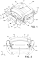
- THE figures 1 to 4 show a disc brake 100 for a motor vehicle comprising a caliper 10 according to one embodiment of the invention.
- the disc brake 100 is for example a so-called “floating caliper” or “sliding caliper” disc brake.
- the disc brake 100 comprises a disc (not shown) mounted integrally in rotation with a wheel (not shown) of the motor vehicle around a transverse wheel axis (not shown).
- the wheel is itself mounted to rotate relative to a chassis (not shown) of the motor vehicle around the wheel axle.
- the disc comprises two opposite flat faces, longitudinal and vertical, oriented perpendicular to the wheel axis.
- the disc brake 100 further comprises a support 101, also called yoke, which is mounted fixed relative to the chassis of the motor vehicle.
- the disc brake 100 further comprises two opposing braking pads 102, 103, each mounted sliding in the yoke 101 along a sliding axis 104, transverse, parallel to the wheel axis, between an active position and an inactive position.
- the braking pads 102, 103 are located on either side of the disc.
- the braking pads 102, 103 each comprise a support plate 105 having a first and a second opposite plane faces 106, 107, longitudinal and vertical, perpendicular to the sliding axis 104.
- the first face 106 of the braking pads 102, 103 is oriented towards the disc and carries a friction lining 108 having a flat, longitudinal and vertical friction face 109, perpendicular to the sliding axis 104.
- the friction face 109 of the friction lining 108 of each of the braking pads 102, 103 is intended to cooperate with the face of the disc located opposite said friction face 109.
- the disc brake 100 also includes a caliper 10 which controls the tightening of the braking pads 102, 103 from their inactive position to their active position, during a braking operation.
- the stirrup 10 comprises a body 11 of molded material itself comprising a base 12, an arch 13 extending the base 12 and a plurality of fingers 14, for example two or three fingers 14, extending the arch 13 facing the base 12.
- the body 11 of the stirrup 10 thus generally has an inverted U shape.
- the arch 13 extends between the base 12 and the fingers 14 generally parallel to the wheel axle, above the disc.
- the vault 13 thus bypasses the disk, covering it.
- the base 12 and the fingers 14 extend radially from the arch 13 towards the wheel axle, on either side of the disc and the braking pads 102, 103.
- the braking pads 102, 103 and the disc are thus interposed between the base 12 and the fingers 14.
- the base 12 is arranged facing a first 102 of the braking pads, while the fingers 14 are arranged facing a second 103 of the braking pads.
- the fingers 14 each have a flat inner face 15 located opposite the second braking pad 103 and cooperating with said second braking pad 103, when it slides between its inactive position and its active position, as well as a flat outer face 16 opposite.
- the interior face 15 of the fingers 14 is longitudinal and vertical, perpendicular to the wheel axis.
- the interior and exterior faces 15, 16 of the fingers 14 form a non-zero angle ⁇ between them, in particular between 1 and 2° inclusive.
- This angle ⁇ corresponds to a relief angle making it easier to unmold the body 11 from the stirrup 10, during its manufacture.
- This angle ⁇ is preferably equal to 1.5° ⁇ 0.5°.
- the exterior face 16 of the fingers 14 defines for example a recess 17 in the body 11 of the stirrup 10, in particular with respect to the arch 13.
- the arch 13 is for example connected to the exterior face 16 of the fingers 14 by via a bead 171 extending from the body 11 generally parallel to the wheel axis, the exterior face 16 thus being set back relative to a top of the bead 171.
- the body 11 of the stirrup 10 is for example mounted sliding relative to the yoke 101 via two guide posts 110 which are parallel to the sliding axes 104 of the braking pads 102, 103 and which are each received in sliding in an associated bore (not shown) of the yoke 101.
- the base 12 further carries at least one actuator, for example a hydraulic or mechanical piston, designed on the one hand to drive the first braking shoe 102 in sliding from its inactive position to its active position, and on the other hand to drive , by reaction, the caliper 10 slides in a direction opposite to that of the first braking pad 102, so that the caliper 10 itself drives, by means of the fingers 14 and their interior face 15, the second braking pad 103 sliding from its inactive position to its active position.
- at least one actuator for example a hydraulic or mechanical piston
- the actuator makes it possible to tighten the first and second braking pads 102, 103 towards each other and to apply their friction face 109 against the opposite faces of the disc.
- the first and second braking pads 102, 103 thus make it possible, by friction against the opposite faces of the disc, to reduce the speed of rotation of the wheel and thus to brake the motor vehicle.
- the body 11 of the stirrup 10 comprises for example two fingers 14, when the base 12 houses an actuator.
- the body 11 of the stirrup 10 comprises for example three fingers 14, when the base 12 houses two actuators.
- the stirrup 10 also includes a protective plate 18 attached to the exterior face 16 of the fingers 14 of the body 11.
- the protective plate 18 covers or even hides all or part of the fingers 14 of the body 11.
- the protective plate 18 thus allows to obstruct one or more empty spaces 19 defined between two adjacent fingers 14, in order to prevent the entry of dust through these empty spaces 19.
- the protective plate 18 is also fixed by screwing to at least one of the fingers 14 of the body 11.
- fixing the protective plate 18 is particularly simple to implement.
- the protective plate 18 can thus be assembled, disassembled and reassembled very easily. Screwing also makes it possible to fix the protective plate 18 to the body 11 of the stirrup 10 whatever its shape or even its geometry. Screw fixing also has the advantages of being reliable and inexpensive.
- the protective plate 18 is for example in contact with or even resting against the exterior face 16 of the fingers 14 of the body 11. This makes it possible to reduce the vibrations of the protective plate 18 and thus the noise associated with these vibrations.
- the protective plate 18 comprises for example a first part in contact with the exterior face 16 of the fingers 14 of the body 11 and a second part which extends the first part in a direction opposite to the vault 13, in particular vertical, and which forms a free end of the protective plate 18.
- the free end of the protection plate 18 is thus arranged at a distance from the stirrup 10, in particular from the fingers 14.
- the second part of the protective plate 18 is for example inclined relative to the first part, towards the caliper 10, in particular the fingers 14, so as to ensure minimal clearance between the protective plate 18 and a wheel gauge (not shown) and thus avoid any interference between the protective plate 18 and the wheel gauge.
- the first and second parts of the protective plate 18 are straight relative to each other, in particular when the shape of the wheel gauge allows it.
- the protective plate 18 is fixed by screwing to two fingers 14 of the body 11.
- the plate protective 18 is fixed by screwing to the two end fingers 14 between which the other finger(s) 14 are interposed.
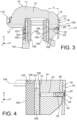
- the stirrup 10 further comprises a fixing screw 20 screwed around a fixing axis 21 in holes 22, 23 provided in correspondence in the protective plate 18 and the finger 14.
- the hole 22 of the protective plate 18 and the hole or bore 23 of the finger 14 are thus both centered on the fixing axis 21.
- the hole 23 of the finger 14 extends from the outer face 16 towards the inner face 15 of the finger 14.
- the hole 23 of the finger 14 is for example through, which makes it possible to evacuate the material shavings when drilling the hole 23 of finger 14.
- the fixing screw 20 comprises for example a countersunk head 24 housed in a recess 25 of the hole 22 of the protective plate 18, of complementary shape with said countersunk head 24 and itself centered on the fixing axis 21, and a body threaded 26 cooperating with a tapping of the hole 23 of the finger 14.
- the recess 25 prevents the countersunk head 24 of the fixing screw 20 from protruding from the protective plate 18.
- the recess 25 of the hole 22 of the protective plate 18 has a frustoconical shape extending around the fixing axis 21.
- a frustoconical surface of the recess 25 forms for example substantially an angle of 45° with the axis of fixing 21 over its entire circumference.
- the recess 25 is for example made by stamping the protective plate 18.
- the threaded body 26 extends for example partly in the hole 22 of the protective plate 18 and partly in the hole 23 of the finger 14 with which it cooperates.
- the hole 23 of the finger 14 is for example only partly threaded, particularly when said hole 23 is through.
- the fixing axis 21 is oriented perpendicular to the interior face 15 of the finger 14.
- the fixing screw 20 is screwed in bias relative to the exterior face 16 of the finger 14. It is also screwed at an angle relative to the protective plate 18. This makes it possible to simplify the machining of the stirrup 10, the same reference can be used for all operations of machining of the caliper 10.
- the fixing screw 20 is for example made of stainless steel. The fixing screw 20 is thus resistant to corrosion.
- the fixing screw 20 is made of steel with resistance class 8.8.
- the fixing screw 20 is for example also heat treated.
- the stirrup comprises several protective plates 18.
- the protective plates 18 each obstruct one of the empty spaces (19) separating two adjacent fingers (14). The detailed description above remains applicable to this variant.
- the caliper 10 and the disc brake 100 described above are particularly advantageous because they make it possible to avoid, by means of the protective plate 18, the entry of dust via the empty space(s) 19 which separate the fingers 14 from the body 11, without however complicating the manufacture of the caliper 10 and the disc brake 100 by fixing the protective plate 18 to the fingers 14 by screwing.
Landscapes
- Engineering & Computer Science (AREA)
- General Engineering & Computer Science (AREA)
- Mechanical Engineering (AREA)
- Braking Arrangements (AREA)
Applications Claiming Priority (2)
| Application Number | Priority Date | Filing Date | Title |
|---|---|---|---|
| FR1873548A FR3090775B1 (fr) | 2018-12-20 | 2018-12-20 | Etrier pour frein a disque comprenant une plaque protectrice vissee et frein a disque comprenant un tel etrier |
| PCT/FR2019/053003 WO2020128228A1 (fr) | 2018-12-20 | 2019-12-10 | Etrier pour frein a disque comprenant une plaque protectrice vissee et frein a disque comprenant un tel etrier |
Publications (2)
| Publication Number | Publication Date |
|---|---|
| EP3874175A1 EP3874175A1 (fr) | 2021-09-08 |
| EP3874175B1 true EP3874175B1 (fr) | 2024-04-03 |
Family
ID=66776475
Family Applications (1)
| Application Number | Title | Priority Date | Filing Date |
|---|---|---|---|
| EP19839373.8A Active EP3874175B1 (fr) | 2018-12-20 | 2019-12-10 | Etrier pour frein a disque comprenant une plaque protectrice vissee et frein a disque comprenant un tel etrier |
Country Status (4)
| Country | Link |
|---|---|
| EP (1) | EP3874175B1 (pl) |
| FR (1) | FR3090775B1 (pl) |
| PL (1) | PL3874175T3 (pl) |
| WO (1) | WO2020128228A1 (pl) |
Families Citing this family (8)
| Publication number | Priority date | Publication date | Assignee | Title |
|---|---|---|---|---|
| JP7271722B2 (ja) * | 2019-12-18 | 2023-05-11 | 日立Astemo株式会社 | ディスクブレーキおよびカバー部品 |
| DE102021206087A1 (de) | 2021-06-15 | 2022-12-15 | Zf Active Safety Gmbh | Bremssattel mit einer Blende |
| DE102021206085A1 (de) | 2021-06-15 | 2022-12-15 | Zf Active Safety Gmbh | Bremssattel mit einer Blende |
| DE102021206084A1 (de) | 2021-06-15 | 2022-12-15 | Zf Active Safety Gmbh | Bremssattel mit einer Blende |
| US12516705B2 (en) * | 2021-07-28 | 2026-01-06 | Zf Active Safety Gmbh | Brake caliper with cover |
| FR3126463B1 (fr) * | 2021-08-30 | 2023-11-24 | Hitachi Astemo France | Élément de couverture pour un frein à disque à étrier flottant, fixe à une chape du frein |
| DE102023200782A1 (de) | 2022-06-13 | 2023-12-14 | Continental Automotive Technologies GmbH | Blende zur lösbaren Fixierung an einem Bremssattelgehäuse und Kraftfahrzeugscheibenbremse umfassend die Blende |
| IT202200018417A1 (it) * | 2022-09-09 | 2024-03-09 | Brembo Spa | Piastrina di copertura e assieme di corpo pinza di freno con piastrina di copertura |
Citations (2)
| Publication number | Priority date | Publication date | Assignee | Title |
|---|---|---|---|---|
| EP1881472B1 (de) * | 2006-07-18 | 2009-01-21 | Lucas Varity s.r.o. | Befestigung des Firmenmarkenzeichens an dem Bremssattel einer Scheibenbremse |
| US20090141514A1 (en) * | 2007-09-20 | 2009-06-04 | Palkovic Andrew L | Brake caliper illumination system |
Family Cites Families (4)
| Publication number | Priority date | Publication date | Assignee | Title |
|---|---|---|---|---|
| DE10027783A1 (de) * | 2000-06-07 | 2002-01-03 | Lucas Automotive Gmbh | Befestigung des Firmenmarkenzeichens an dem Bremssattel einer Scheibenbremse |
| JP5715932B2 (ja) * | 2011-11-18 | 2015-05-13 | 本田技研工業株式会社 | ディスクブレーキ装置 |
| FR3045750B1 (fr) | 2015-12-16 | 2019-05-03 | Foundation Brakes France | Etrier de frein a disque equipe d'une plaque protectrice integrant des plots de fixation au corps d'etrier |
| FR3045752B1 (fr) | 2015-12-16 | 2017-12-22 | Foundation Brakes France | Etrier de frein a disque equipe d'une plaque protectrice portant des taquets rotatifs de fixation au corps d'etrier |
-
2018
- 2018-12-20 FR FR1873548A patent/FR3090775B1/fr active Active
-
2019
- 2019-12-10 PL PL19839373.8T patent/PL3874175T3/pl unknown
- 2019-12-10 EP EP19839373.8A patent/EP3874175B1/fr active Active
- 2019-12-10 WO PCT/FR2019/053003 patent/WO2020128228A1/fr not_active Ceased
Patent Citations (2)
| Publication number | Priority date | Publication date | Assignee | Title |
|---|---|---|---|---|
| EP1881472B1 (de) * | 2006-07-18 | 2009-01-21 | Lucas Varity s.r.o. | Befestigung des Firmenmarkenzeichens an dem Bremssattel einer Scheibenbremse |
| US20090141514A1 (en) * | 2007-09-20 | 2009-06-04 | Palkovic Andrew L | Brake caliper illumination system |
Also Published As
| Publication number | Publication date |
|---|---|
| FR3090775B1 (fr) | 2022-02-04 |
| PL3874175T3 (pl) | 2024-08-26 |
| WO2020128228A1 (fr) | 2020-06-25 |
| EP3874175A1 (fr) | 2021-09-08 |
| FR3090775A1 (fr) | 2020-06-26 |
Similar Documents
| Publication | Publication Date | Title |
|---|---|---|
| EP3874175B1 (fr) | Etrier pour frein a disque comprenant une plaque protectrice vissee et frein a disque comprenant un tel etrier | |
| EP2992236B2 (fr) | Frein à disque à étrier fixe et à patins de frein stabilisés, et procédés associés d'assemblage et de remplacement d'un patin | |
| EP2659156B1 (fr) | Frein a disque a cartouche de conversion munie d'un dispositif antimatage. | |
| EP2746611B1 (fr) | Roue d'aéronef équipée de boulons-barrettes | |
| EP2373872A2 (fr) | Roue de turbine equipee d'un dispositif de retenue axiale verrouillant des pales par rapport a un disque | |
| FR2682439A1 (fr) | Embrayage a disques structuraux en particulier en carbone-carbone. | |
| EP0784759B1 (fr) | Frein a disque a montage ameliore | |
| EP0722542B1 (fr) | Frein a disque a etrier coulissant et colonnette pour un tel frein a disque | |
| EP3071859B1 (fr) | Frein à disque de véhicule automobile à jeu transversal réduit entre colonnettes et alésages | |
| EP2691670A1 (fr) | Volant moteur equipe de moyens de retenue des vis de fixation sur le vilebrequin | |
| FR2632033A1 (pl) | ||
| EP0694134B1 (fr) | Ensemble d'un element de friction equipe d'un ressort pour frein a disque | |
| FR2604500A1 (fr) | Frein a disque a garnitures partielles | |
| FR2698425A1 (fr) | Disque de frein à organe atténuateur de vibrations. | |
| FR2800825A1 (fr) | Rampe a billes et cylindre de freins comportant une telle rampe | |
| FR2988450A1 (fr) | Disque de frein et dispositif de freinage d'une roue d'un vehicule associe | |
| EP0395460B1 (fr) | Frein à disque à étrier coulissant | |
| JP2009133356A (ja) | フローティングキャリパ型ディスクブレーキ | |
| FR2905155A1 (fr) | Frein a disque comportant un axe dont une portee presente une section de profil non circulaire | |
| FR3062442B1 (fr) | Mecanisme d'embrayage, notamment pour vehicule automobile | |
| FR2965027A1 (fr) | Frein a disque a etrier flottant pour vehicule automobile | |
| FR2745051A1 (fr) | Montage de butee de debrayage, notamment pour vehicule automobile | |
| FR3024190A1 (fr) | Patin de frein equipe d'un dispositif antibruit | |
| EP0044772B1 (fr) | Frein à disque à étrier mobile | |
| JP4432266B2 (ja) | ディスクブレーキ |
Legal Events
| Date | Code | Title | Description |
|---|---|---|---|
| STAA | Information on the status of an ep patent application or granted ep patent |
Free format text: STATUS: UNKNOWN |
|
| STAA | Information on the status of an ep patent application or granted ep patent |
Free format text: STATUS: THE INTERNATIONAL PUBLICATION HAS BEEN MADE |
|
| TPAC | Observations filed by third parties |
Free format text: ORIGINAL CODE: EPIDOSNTIPA |
|
| PUAI | Public reference made under article 153(3) epc to a published international application that has entered the european phase |
Free format text: ORIGINAL CODE: 0009012 |
|
| STAA | Information on the status of an ep patent application or granted ep patent |
Free format text: STATUS: REQUEST FOR EXAMINATION WAS MADE |
|
| 17P | Request for examination filed |
Effective date: 20210603 |
|
| AK | Designated contracting states |
Kind code of ref document: A1 Designated state(s): AL AT BE BG CH CY CZ DE DK EE ES FI FR GB GR HR HU IE IS IT LI LT LU LV MC MK MT NL NO PL PT RO RS SE SI SK SM TR |
|
| RAP3 | Party data changed (applicant data changed or rights of an application transferred) |
Owner name: HITACHI ASTEMO FRANCE |
|
| DAV | Request for validation of the european patent (deleted) | ||
| DAX | Request for extension of the european patent (deleted) | ||
| STAA | Information on the status of an ep patent application or granted ep patent |
Free format text: STATUS: EXAMINATION IS IN PROGRESS |
|
| 17Q | First examination report despatched |
Effective date: 20220602 |
|
| GRAP | Despatch of communication of intention to grant a patent |
Free format text: ORIGINAL CODE: EPIDOSNIGR1 |
|
| STAA | Information on the status of an ep patent application or granted ep patent |
Free format text: STATUS: GRANT OF PATENT IS INTENDED |
|
| INTG | Intention to grant announced |
Effective date: 20231121 |
|
| GRAS | Grant fee paid |
Free format text: ORIGINAL CODE: EPIDOSNIGR3 |
|
| GRAA | (expected) grant |
Free format text: ORIGINAL CODE: 0009210 |
|
| STAA | Information on the status of an ep patent application or granted ep patent |
Free format text: STATUS: THE PATENT HAS BEEN GRANTED |
|
| AK | Designated contracting states |
Kind code of ref document: B1 Designated state(s): AL AT BE BG CH CY CZ DE DK EE ES FI FR GB GR HR HU IE IS IT LI LT LU LV MC MK MT NL NO PL PT RO RS SE SI SK SM TR |
|
| REG | Reference to a national code |
Ref country code: CH Ref legal event code: EP |
|
| REG | Reference to a national code |
Ref country code: IE Ref legal event code: FG4D Free format text: LANGUAGE OF EP DOCUMENT: FRENCH |
|
| REG | Reference to a national code |
Ref country code: DE Ref legal event code: R096 Ref document number: 602019049686 Country of ref document: DE |
|
| REG | Reference to a national code |
Ref country code: LT Ref legal event code: MG9D |
|
| REG | Reference to a national code |
Ref country code: NL Ref legal event code: MP Effective date: 20240403 |
|
| REG | Reference to a national code |
Ref country code: AT Ref legal event code: MK05 Ref document number: 1672631 Country of ref document: AT Kind code of ref document: T Effective date: 20240403 |
|
| PG25 | Lapsed in a contracting state [announced via postgrant information from national office to epo] |
Ref country code: NL Free format text: LAPSE BECAUSE OF FAILURE TO SUBMIT A TRANSLATION OF THE DESCRIPTION OR TO PAY THE FEE WITHIN THE PRESCRIBED TIME-LIMIT Effective date: 20240403 |
|
| PG25 | Lapsed in a contracting state [announced via postgrant information from national office to epo] |
Ref country code: NL Free format text: LAPSE BECAUSE OF FAILURE TO SUBMIT A TRANSLATION OF THE DESCRIPTION OR TO PAY THE FEE WITHIN THE PRESCRIBED TIME-LIMIT Effective date: 20240403 |
|
| PG25 | Lapsed in a contracting state [announced via postgrant information from national office to epo] |
Ref country code: IS Free format text: LAPSE BECAUSE OF FAILURE TO SUBMIT A TRANSLATION OF THE DESCRIPTION OR TO PAY THE FEE WITHIN THE PRESCRIBED TIME-LIMIT Effective date: 20240803 |
|
| PG25 | Lapsed in a contracting state [announced via postgrant information from national office to epo] |
Ref country code: BG Free format text: LAPSE BECAUSE OF FAILURE TO SUBMIT A TRANSLATION OF THE DESCRIPTION OR TO PAY THE FEE WITHIN THE PRESCRIBED TIME-LIMIT Effective date: 20240403 |
|
| PG25 | Lapsed in a contracting state [announced via postgrant information from national office to epo] |
Ref country code: HR Free format text: LAPSE BECAUSE OF FAILURE TO SUBMIT A TRANSLATION OF THE DESCRIPTION OR TO PAY THE FEE WITHIN THE PRESCRIBED TIME-LIMIT Effective date: 20240403 Ref country code: FI Free format text: LAPSE BECAUSE OF FAILURE TO SUBMIT A TRANSLATION OF THE DESCRIPTION OR TO PAY THE FEE WITHIN THE PRESCRIBED TIME-LIMIT Effective date: 20240403 |
|
| PG25 | Lapsed in a contracting state [announced via postgrant information from national office to epo] |
Ref country code: GR Free format text: LAPSE BECAUSE OF FAILURE TO SUBMIT A TRANSLATION OF THE DESCRIPTION OR TO PAY THE FEE WITHIN THE PRESCRIBED TIME-LIMIT Effective date: 20240704 |
|
| PG25 | Lapsed in a contracting state [announced via postgrant information from national office to epo] |
Ref country code: PT Free format text: LAPSE BECAUSE OF FAILURE TO SUBMIT A TRANSLATION OF THE DESCRIPTION OR TO PAY THE FEE WITHIN THE PRESCRIBED TIME-LIMIT Effective date: 20240805 |
|
| PG25 | Lapsed in a contracting state [announced via postgrant information from national office to epo] |
Ref country code: ES Free format text: LAPSE BECAUSE OF FAILURE TO SUBMIT A TRANSLATION OF THE DESCRIPTION OR TO PAY THE FEE WITHIN THE PRESCRIBED TIME-LIMIT Effective date: 20240403 |
|
| PG25 | Lapsed in a contracting state [announced via postgrant information from national office to epo] |
Ref country code: CZ Free format text: LAPSE BECAUSE OF FAILURE TO SUBMIT A TRANSLATION OF THE DESCRIPTION OR TO PAY THE FEE WITHIN THE PRESCRIBED TIME-LIMIT Effective date: 20240403 |
|
| PG25 | Lapsed in a contracting state [announced via postgrant information from national office to epo] |
Ref country code: AT Free format text: LAPSE BECAUSE OF FAILURE TO SUBMIT A TRANSLATION OF THE DESCRIPTION OR TO PAY THE FEE WITHIN THE PRESCRIBED TIME-LIMIT Effective date: 20240403 |
|
| PG25 | Lapsed in a contracting state [announced via postgrant information from national office to epo] |
Ref country code: LV Free format text: LAPSE BECAUSE OF FAILURE TO SUBMIT A TRANSLATION OF THE DESCRIPTION OR TO PAY THE FEE WITHIN THE PRESCRIBED TIME-LIMIT Effective date: 20240403 |
|
| PG25 | Lapsed in a contracting state [announced via postgrant information from national office to epo] |
Ref country code: PT Free format text: LAPSE BECAUSE OF FAILURE TO SUBMIT A TRANSLATION OF THE DESCRIPTION OR TO PAY THE FEE WITHIN THE PRESCRIBED TIME-LIMIT Effective date: 20240805 Ref country code: NO Free format text: LAPSE BECAUSE OF FAILURE TO SUBMIT A TRANSLATION OF THE DESCRIPTION OR TO PAY THE FEE WITHIN THE PRESCRIBED TIME-LIMIT Effective date: 20240703 Ref country code: LV Free format text: LAPSE BECAUSE OF FAILURE TO SUBMIT A TRANSLATION OF THE DESCRIPTION OR TO PAY THE FEE WITHIN THE PRESCRIBED TIME-LIMIT Effective date: 20240403 Ref country code: IS Free format text: LAPSE BECAUSE OF FAILURE TO SUBMIT A TRANSLATION OF THE DESCRIPTION OR TO PAY THE FEE WITHIN THE PRESCRIBED TIME-LIMIT Effective date: 20240803 Ref country code: HR Free format text: LAPSE BECAUSE OF FAILURE TO SUBMIT A TRANSLATION OF THE DESCRIPTION OR TO PAY THE FEE WITHIN THE PRESCRIBED TIME-LIMIT Effective date: 20240403 Ref country code: GR Free format text: LAPSE BECAUSE OF FAILURE TO SUBMIT A TRANSLATION OF THE DESCRIPTION OR TO PAY THE FEE WITHIN THE PRESCRIBED TIME-LIMIT Effective date: 20240704 Ref country code: FI Free format text: LAPSE BECAUSE OF FAILURE TO SUBMIT A TRANSLATION OF THE DESCRIPTION OR TO PAY THE FEE WITHIN THE PRESCRIBED TIME-LIMIT Effective date: 20240403 Ref country code: ES Free format text: LAPSE BECAUSE OF FAILURE TO SUBMIT A TRANSLATION OF THE DESCRIPTION OR TO PAY THE FEE WITHIN THE PRESCRIBED TIME-LIMIT Effective date: 20240403 Ref country code: CZ Free format text: LAPSE BECAUSE OF FAILURE TO SUBMIT A TRANSLATION OF THE DESCRIPTION OR TO PAY THE FEE WITHIN THE PRESCRIBED TIME-LIMIT Effective date: 20240403 Ref country code: BG Free format text: LAPSE BECAUSE OF FAILURE TO SUBMIT A TRANSLATION OF THE DESCRIPTION OR TO PAY THE FEE WITHIN THE PRESCRIBED TIME-LIMIT Effective date: 20240403 Ref country code: AT Free format text: LAPSE BECAUSE OF FAILURE TO SUBMIT A TRANSLATION OF THE DESCRIPTION OR TO PAY THE FEE WITHIN THE PRESCRIBED TIME-LIMIT Effective date: 20240403 Ref country code: RS Free format text: LAPSE BECAUSE OF FAILURE TO SUBMIT A TRANSLATION OF THE DESCRIPTION OR TO PAY THE FEE WITHIN THE PRESCRIBED TIME-LIMIT Effective date: 20240703 |
|
| REG | Reference to a national code |
Ref country code: DE Ref legal event code: R097 Ref document number: 602019049686 Country of ref document: DE |
|
| PG25 | Lapsed in a contracting state [announced via postgrant information from national office to epo] |
Ref country code: DK Free format text: LAPSE BECAUSE OF FAILURE TO SUBMIT A TRANSLATION OF THE DESCRIPTION OR TO PAY THE FEE WITHIN THE PRESCRIBED TIME-LIMIT Effective date: 20240403 |
|
| PG25 | Lapsed in a contracting state [announced via postgrant information from national office to epo] |
Ref country code: EE Free format text: LAPSE BECAUSE OF FAILURE TO SUBMIT A TRANSLATION OF THE DESCRIPTION OR TO PAY THE FEE WITHIN THE PRESCRIBED TIME-LIMIT Effective date: 20240403 |
|
| PG25 | Lapsed in a contracting state [announced via postgrant information from national office to epo] |
Ref country code: SK Free format text: LAPSE BECAUSE OF FAILURE TO SUBMIT A TRANSLATION OF THE DESCRIPTION OR TO PAY THE FEE WITHIN THE PRESCRIBED TIME-LIMIT Effective date: 20240403 Ref country code: RO Free format text: LAPSE BECAUSE OF FAILURE TO SUBMIT A TRANSLATION OF THE DESCRIPTION OR TO PAY THE FEE WITHIN THE PRESCRIBED TIME-LIMIT Effective date: 20240403 |
|
| PG25 | Lapsed in a contracting state [announced via postgrant information from national office to epo] |
Ref country code: SM Free format text: LAPSE BECAUSE OF FAILURE TO SUBMIT A TRANSLATION OF THE DESCRIPTION OR TO PAY THE FEE WITHIN THE PRESCRIBED TIME-LIMIT Effective date: 20240403 |
|
| PG25 | Lapsed in a contracting state [announced via postgrant information from national office to epo] |
Ref country code: SM Free format text: LAPSE BECAUSE OF FAILURE TO SUBMIT A TRANSLATION OF THE DESCRIPTION OR TO PAY THE FEE WITHIN THE PRESCRIBED TIME-LIMIT Effective date: 20240403 Ref country code: SK Free format text: LAPSE BECAUSE OF FAILURE TO SUBMIT A TRANSLATION OF THE DESCRIPTION OR TO PAY THE FEE WITHIN THE PRESCRIBED TIME-LIMIT Effective date: 20240403 Ref country code: RO Free format text: LAPSE BECAUSE OF FAILURE TO SUBMIT A TRANSLATION OF THE DESCRIPTION OR TO PAY THE FEE WITHIN THE PRESCRIBED TIME-LIMIT Effective date: 20240403 Ref country code: EE Free format text: LAPSE BECAUSE OF FAILURE TO SUBMIT A TRANSLATION OF THE DESCRIPTION OR TO PAY THE FEE WITHIN THE PRESCRIBED TIME-LIMIT Effective date: 20240403 Ref country code: DK Free format text: LAPSE BECAUSE OF FAILURE TO SUBMIT A TRANSLATION OF THE DESCRIPTION OR TO PAY THE FEE WITHIN THE PRESCRIBED TIME-LIMIT Effective date: 20240403 |
|
| PLBE | No opposition filed within time limit |
Free format text: ORIGINAL CODE: 0009261 |
|
| STAA | Information on the status of an ep patent application or granted ep patent |
Free format text: STATUS: NO OPPOSITION FILED WITHIN TIME LIMIT |
|
| 26N | No opposition filed |
Effective date: 20250106 |
|
| PG25 | Lapsed in a contracting state [announced via postgrant information from national office to epo] |
Ref country code: SI Free format text: LAPSE BECAUSE OF FAILURE TO SUBMIT A TRANSLATION OF THE DESCRIPTION OR TO PAY THE FEE WITHIN THE PRESCRIBED TIME-LIMIT Effective date: 20240403 |
|
| PG25 | Lapsed in a contracting state [announced via postgrant information from national office to epo] |
Ref country code: MC Free format text: LAPSE BECAUSE OF FAILURE TO SUBMIT A TRANSLATION OF THE DESCRIPTION OR TO PAY THE FEE WITHIN THE PRESCRIBED TIME-LIMIT Effective date: 20240403 |
|
| REG | Reference to a national code |
Ref country code: CH Ref legal event code: PL |
|
| PG25 | Lapsed in a contracting state [announced via postgrant information from national office to epo] |
Ref country code: LU Free format text: LAPSE BECAUSE OF NON-PAYMENT OF DUE FEES Effective date: 20241210 |
|
| PG25 | Lapsed in a contracting state [announced via postgrant information from national office to epo] |
Ref country code: SE Free format text: LAPSE BECAUSE OF FAILURE TO SUBMIT A TRANSLATION OF THE DESCRIPTION OR TO PAY THE FEE WITHIN THE PRESCRIBED TIME-LIMIT Effective date: 20240403 |
|
| REG | Reference to a national code |
Ref country code: BE Ref legal event code: MM Effective date: 20241231 |
|
| PG25 | Lapsed in a contracting state [announced via postgrant information from national office to epo] |
Ref country code: BE Free format text: LAPSE BECAUSE OF NON-PAYMENT OF DUE FEES Effective date: 20241231 |
|
| PG25 | Lapsed in a contracting state [announced via postgrant information from national office to epo] |
Ref country code: CH Free format text: LAPSE BECAUSE OF NON-PAYMENT OF DUE FEES Effective date: 20241231 |
|
| PG25 | Lapsed in a contracting state [announced via postgrant information from national office to epo] |
Ref country code: IE Free format text: LAPSE BECAUSE OF NON-PAYMENT OF DUE FEES Effective date: 20241210 |
|
| PGFP | Annual fee paid to national office [announced via postgrant information from national office to epo] |
Ref country code: DE Payment date: 20251126 Year of fee payment: 7 |
|
| PGFP | Annual fee paid to national office [announced via postgrant information from national office to epo] |
Ref country code: GB Payment date: 20251119 Year of fee payment: 7 |
|
| PGFP | Annual fee paid to national office [announced via postgrant information from national office to epo] |
Ref country code: FR Payment date: 20251120 Year of fee payment: 7 |
|
| PGFP | Annual fee paid to national office [announced via postgrant information from national office to epo] |
Ref country code: PL Payment date: 20251124 Year of fee payment: 7 |
|
| PG25 | Lapsed in a contracting state [announced via postgrant information from national office to epo] |
Ref country code: IT Free format text: LAPSE BECAUSE OF FAILURE TO SUBMIT A TRANSLATION OF THE DESCRIPTION OR TO PAY THE FEE WITHIN THE PRESCRIBED TIME-LIMIT Effective date: 20240403 |