EP3874175B1 - Calliper for disc brake, comprising a screw-fitted protective plate and disc brake comprising such a calliper - Google Patents
Calliper for disc brake, comprising a screw-fitted protective plate and disc brake comprising such a calliper Download PDFInfo
- Publication number
- EP3874175B1 EP3874175B1 EP19839373.8A EP19839373A EP3874175B1 EP 3874175 B1 EP3874175 B1 EP 3874175B1 EP 19839373 A EP19839373 A EP 19839373A EP 3874175 B1 EP3874175 B1 EP 3874175B1
- Authority
- EP
- European Patent Office
- Prior art keywords
- fingers
- protective plate
- calliper
- disc brake
- face
- Prior art date
- Legal status (The legal status is an assumption and is not a legal conclusion. Google has not performed a legal analysis and makes no representation as to the accuracy of the status listed.)
- Active
Links
- 230000001681 protective effect Effects 0.000 title claims description 58
- 239000000463 material Substances 0.000 claims description 8
- 230000000295 complement effect Effects 0.000 claims description 3
- 229910001220 stainless steel Inorganic materials 0.000 claims description 3
- 239000010935 stainless steel Substances 0.000 claims description 3
- 208000031968 Cadaver Diseases 0.000 description 3
- 239000011324 bead Substances 0.000 description 3
- 239000000428 dust Substances 0.000 description 3
- 238000003754 machining Methods 0.000 description 2
- 238000004519 manufacturing process Methods 0.000 description 2
- 238000010079 rubber tapping Methods 0.000 description 2
- 229910000831 Steel Inorganic materials 0.000 description 1
- 210000000078 claw Anatomy 0.000 description 1
- 230000007797 corrosion Effects 0.000 description 1
- 238000005260 corrosion Methods 0.000 description 1
- 238000005553 drilling Methods 0.000 description 1
- 230000014759 maintenance of location Effects 0.000 description 1
- 230000000284 resting effect Effects 0.000 description 1
- 239000010959 steel Substances 0.000 description 1
Images
Classifications
-
- F—MECHANICAL ENGINEERING; LIGHTING; HEATING; WEAPONS; BLASTING
- F16—ENGINEERING ELEMENTS AND UNITS; GENERAL MEASURES FOR PRODUCING AND MAINTAINING EFFECTIVE FUNCTIONING OF MACHINES OR INSTALLATIONS; THERMAL INSULATION IN GENERAL
- F16D—COUPLINGS FOR TRANSMITTING ROTATION; CLUTCHES; BRAKES
- F16D55/00—Brakes with substantially-radial braking surfaces pressed together in axial direction, e.g. disc brakes
- F16D55/02—Brakes with substantially-radial braking surfaces pressed together in axial direction, e.g. disc brakes with axially-movable discs or pads pressed against axially-located rotating members
- F16D55/22—Brakes with substantially-radial braking surfaces pressed together in axial direction, e.g. disc brakes with axially-movable discs or pads pressed against axially-located rotating members by clamping an axially-located rotating disc between movable braking members, e.g. movable brake discs or brake pads
-
- F—MECHANICAL ENGINEERING; LIGHTING; HEATING; WEAPONS; BLASTING
- F16—ENGINEERING ELEMENTS AND UNITS; GENERAL MEASURES FOR PRODUCING AND MAINTAINING EFFECTIVE FUNCTIONING OF MACHINES OR INSTALLATIONS; THERMAL INSULATION IN GENERAL
- F16D—COUPLINGS FOR TRANSMITTING ROTATION; CLUTCHES; BRAKES
- F16D65/00—Parts or details
- F16D65/005—Components of axially engaging brakes not otherwise provided for
- F16D65/0068—Brake calipers
-
- F—MECHANICAL ENGINEERING; LIGHTING; HEATING; WEAPONS; BLASTING
- F16—ENGINEERING ELEMENTS AND UNITS; GENERAL MEASURES FOR PRODUCING AND MAINTAINING EFFECTIVE FUNCTIONING OF MACHINES OR INSTALLATIONS; THERMAL INSULATION IN GENERAL
- F16D—COUPLINGS FOR TRANSMITTING ROTATION; CLUTCHES; BRAKES
- F16D65/00—Parts or details
- F16D65/005—Components of axially engaging brakes not otherwise provided for
- F16D65/0081—Brake covers
-
- F—MECHANICAL ENGINEERING; LIGHTING; HEATING; WEAPONS; BLASTING
- F16—ENGINEERING ELEMENTS AND UNITS; GENERAL MEASURES FOR PRODUCING AND MAINTAINING EFFECTIVE FUNCTIONING OF MACHINES OR INSTALLATIONS; THERMAL INSULATION IN GENERAL
- F16D—COUPLINGS FOR TRANSMITTING ROTATION; CLUTCHES; BRAKES
- F16D65/00—Parts or details
- F16D65/02—Braking members; Mounting thereof
- F16D65/04—Bands, shoes or pads; Pivots or supporting members therefor
- F16D65/092—Bands, shoes or pads; Pivots or supporting members therefor for axially-engaging brakes, e.g. disc brakes
- F16D65/095—Pivots or supporting members therefor
-
- F—MECHANICAL ENGINEERING; LIGHTING; HEATING; WEAPONS; BLASTING
- F16—ENGINEERING ELEMENTS AND UNITS; GENERAL MEASURES FOR PRODUCING AND MAINTAINING EFFECTIVE FUNCTIONING OF MACHINES OR INSTALLATIONS; THERMAL INSULATION IN GENERAL
- F16D—COUPLINGS FOR TRANSMITTING ROTATION; CLUTCHES; BRAKES
- F16D55/00—Brakes with substantially-radial braking surfaces pressed together in axial direction, e.g. disc brakes
- F16D2055/0004—Parts or details of disc brakes
- F16D2055/0016—Brake calipers
-
- F—MECHANICAL ENGINEERING; LIGHTING; HEATING; WEAPONS; BLASTING
- F16—ENGINEERING ELEMENTS AND UNITS; GENERAL MEASURES FOR PRODUCING AND MAINTAINING EFFECTIVE FUNCTIONING OF MACHINES OR INSTALLATIONS; THERMAL INSULATION IN GENERAL
- F16D—COUPLINGS FOR TRANSMITTING ROTATION; CLUTCHES; BRAKES
- F16D55/00—Brakes with substantially-radial braking surfaces pressed together in axial direction, e.g. disc brakes
- F16D2055/0004—Parts or details of disc brakes
- F16D2055/0037—Protective covers
Landscapes
- Engineering & Computer Science (AREA)
- General Engineering & Computer Science (AREA)
- Mechanical Engineering (AREA)
- Braking Arrangements (AREA)
Description
L'invention se rapporte à un étrier pour frein à disque de véhicule automobile, ainsi qu'à un frein à disque comprenant un tel étrier. Plus précisément, l'invention se rapporte à un étrier comprenant un corps en matériau moulé et une plaque protectrice fixée sur ledit corps.The invention relates to a caliper for a motor vehicle disc brake, as well as to a disc brake comprising such a caliper. More specifically, the invention relates to a stirrup comprising a body of molded material and a protective plate fixed to said body.
De manière connue, un étrier pour frein à disque de véhicule automobile comprend un corps en matériau moulé comprenant lui-même une base, une voûte prolongeant la base et une pluralité de doigts prolongeant la voûte, en regard de la base, le corps d'étrier présentant ainsi globalement une forme de U inversé.In known manner, a caliper for a motor vehicle disc brake comprises a body of molded material itself comprising a base, an arch extending the base and a plurality of fingers extending the arch, facing the base, the body of stirrup thus generally having an inverted U shape.
Les doigts définissent entre eux un ou plusieurs espaces vides donnant accès à la base du corps où un ou plusieurs actionneurs sont logés en vue d'entraîner un premier patin de glissement du frein à disque en coulissement vers un disque qui est interposé entre la base et les doigts du corps et qui est solidaire en rotation d'une roue de véhicule automobile, un deuxième patin de glissement étant en outre entraîné en coulissement vers le disque par les doigts du corps de l'étrier lui-même monté coulissant.The fingers define between them one or more empty spaces giving access to the base of the body where one or more actuators are housed in order to drive a first sliding pad of the disc brake in sliding towards a disc which is interposed between the base and the fingers of the body and which is integral in rotation with a motor vehicle wheel, a second sliding shoe being further driven to slide towards the disc by the fingers of the body of the caliper itself slidably mounted.
Ce ou ces espaces vides, qui séparent les doigts, autorisent toutefois l'entrée de poussières entre les doigts et la base, de sorte qu'il a été proposé de fixer une plaque protectrice aux doigts du corps afin de couvrir les doigts et ainsi d'obstruer ce ou ces espaces vides.This or these empty spaces, which separate the fingers, however allow the entry of dust between the fingers and the base, so that it has been proposed to attach a protective plate to the fingers of the body in order to cover the fingers and thus 'obstruct this or these empty spaces.
Plusieurs solutions ont été proposées pour fixer la plaque protectrice aux doigts du corps d'étrier.Several solutions have been proposed for attaching the protective plate to the fingers of the caliper body.
Le document
Il a aussi été proposé dans le document
Or, ces solutions de fixation empêchent un démontage et un remontage aisés de la plaque protectrice une fois cette dernière montée sur le corps d'étrier. Ces solutions restent en outre relativement compliquées à mettre en oeuvre pour le montage de la plaque protectrice sur le corps d'étrier.However, these fixing solutions prevent easy disassembly and reassembly of the protective plate once the latter is mounted on the caliper body. These solutions also remain relatively complicated to implement for mounting the protective plate on the caliper body.
Les documents
La présente invention a pour objectif de proposer un étrier pour frein à disque comprenant une plaque protectrice qui peut être facilement montée, démontée et remontée sur un corps en matériau moulé de l'étrier.The objective of the present invention is to provide a disc brake caliper comprising a protective plate which can be easily mounted, disassembled and reassembled on a molded material body of the caliper.
A cet effet, l'invention propose un étrier pour frein à disque comprenant un corps en matériau moulé et une plaque protectrice qui est fixée par vissage audit corps.For this purpose, the invention proposes a caliper for a disc brake comprising a body of molded material and a protective plate which is fixed by screwing to said body.
Plus précisément, l'invention a pour objet un étrier pour frein à disque, comprenant un corps en matériau moulé comprenant lui-même :
- une base,
- une voûte prolongeant la base,
- au moins deux doigts prolongeant la voûte et comprenant chacun une face intérieure plane agencée en regard de la base et destinée à coopérer avec un patin de freinage du frein à disque et une face extérieure plane opposée, chacun des doigts étant séparés du ou des doigts lui étant adjacents par un espace vide, les faces intérieure et extérieure formant entre elles un angle non nul,
- une plaque protectrice rapportée sur la face extérieure des doigts, de sorte à couvrir au moins en partie lesdits doigts, de sorte à obstruer le ou au moins un des espaces vides, la plaque protectrice étant fixée par vissage à l'un au moins des doigts, et
- au moins une vis de fixation vissée autour d'un axe de fixation dans des trous ménagés en correspondance dans la plaque protectrice et l'un des doigts du corps, l'axe de fixation étant orienté perpendiculairement à la face intérieure.
- a base,
- a vault extending the base,
- at least two fingers extending the arch and each comprising a flat interior face arranged opposite the base and intended to cooperate with a braking pad of the disc brake and an opposite flat exterior face, each of the fingers being separated from the finger(s) being adjacent by an empty space, the interior and exterior faces forming a non-zero angle between them,
- a protective plate attached to the exterior face of the fingers, so as to cover at least partly said fingers, so as to obstruct the or at least one of the empty spaces, the protective plate being fixed by screwing to at least one of the fingers , And
- at least one fixing screw screwed around a fixing axis in holes made correspondingly in the protective plate and one of the fingers of the body, the fixing axis being oriented perpendicular to the interior face.
Selon des variantes de réalisation qui peuvent être prises ensemble ou séparément :
- la plaque protectrice couvre entièrement les doigts ;
- la plaque protectrice est fixée par vissage à deux doigts du corps ;
- le trou dudit doigt s'étend depuis la face extérieure vers la face intérieure ;
- le trou dudit doigt est traversant ;
- la vis de fixation comprend une tête fraisée logée dans un évidement du trou de la plaque protectrice, de forme complémentaire avec ladite tête fraisée, et un corps fileté coopérant avec un taraudage du trou dudit doigt ;
- la vis de fixation est réalisée en acier inoxydable.
- the protective plate completely covers the fingers;
- the protective plate is fixed by screwing to two fingers of the body;
- the hole of said finger extends from the exterior face towards the interior face;
- the hole of said finger is through;
- the fixing screw comprises a countersunk head housed in a recess in the hole of the protective plate, of complementary shape with said countersunk head, and a threaded body cooperating with a tapping of the hole of said finger;
- the fixing screw is made of stainless steel.
L'invention a aussi pour objet un frein à disque pour véhicule automobile comprenant un étrier tel que précédemment décrit.The invention also relates to a disc brake for a motor vehicle comprising a caliper as previously described.
D'autres aspects, buts, avantages et caractéristiques de l'invention apparaîtront mieux à la lecture de la description détaillée suivante de formes de réalisation préférés de celle-ci, donnée à titre d'exemple non limitatif, et faite en référence aux dessins annexés sur lesquels :
- La
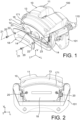
figure 1 est une vue en perspective, éclatée, d'un frein à disque comprenant un étrier selon un mode de réalisation de l'invention ; - La
figure 2 est une vue de face du frein à disque illustré à lafigure 1 ; - la
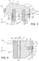
figure 3 est une vue en coupe transversale du frein à disque illustré auxfigures 1 et 2 ; - La
figure 4 est une vue de détail de lafigure 3 .
- There
figure 1 is an exploded perspective view of a disc brake comprising a caliper according to one embodiment of the invention; - There
figure 2 is a front view of the disc brake shown infigure 1 ; - there
Figure 3 is a cross-sectional view of the disc brake shown infigures 1 and 2 ; - There
Figure 4 is a detailed view of theFigure 3 .
Les
Dans la suite de la description, il est adopté à titre non limitatif des orientations longitudinale, verticale et transversale indiquées par le trièdre L, V, T sur les figures. Les orientations longitudinale L et transversale T sont horizontales dans la représentation des
Le frein à disque 100 comprend un disque (non représenté) monté solidaire en rotation avec une roue (non représentée) du véhicule automobile autour d'un axe de roue (non représenté) transversal. La roue est elle-même montée tournante par rapport à un châssis (non représenté) du véhicule automobile autour de l'axe de roue. Le disque comprend deux faces planes opposées, longitudinales et verticales, orientées perpendiculairement à l'axe de roue.The
Le frein à disque 100 comprend en outre un support 101, aussi appelé chape, qui est monté fixe par rapport au châssis du véhicule automobile.The
Le frein à disque 100 comprend encore deux patins de freinage 102, 103 opposés, chacun montés coulissant dans la chape 101 suivant un axe de coulissement 104, transversal, parallèle à l'axe de roue, entre une position active et une position inactive. Les patins de freinage 102, 103 sont situés de part et d'autre du disque.The
Les patins de freinage 102, 103 comprennent chacun une plaque de support 105 présentant une première et une deuxième faces 106, 107 planes opposées, longitudinales et verticales, perpendiculaires à l'axe de coulissement 104.The
La première face 106 des patins de freinage 102, 103 est orientée vers le disque et porte une garniture de frottement 108 présentant une face de frottement 109 plane, longitudinale et verticale, perpendiculaire à l'axe de coulissement 104. La face de frottement 109 de la garniture de frottement 108 de chacun des patins de freinage 102, 103 est destinée à coopérer avec la face du disque située en regard de ladite face de frottement 109.The
En position active, la face de frottement 109 de chacune des garnitures de frottement 108 est en appui contre la face du disque avec laquelle ladite face de frottement 109 est en vis-à-vis. En position inactive, la face de frottement 109 de chacune des garnitures de frottement 108 est écartée transversalement de la face du disque avec laquelle ladite face de frottement 109 est en vis-à-vis.In the active position, the
Comme indiqué précédemment, le frein à disque 100 comprend aussi un étrier 10 qui commande le serrage des patins de freinage 102, 103 depuis leur position inactive vers leur position active, lors d'une opération de freinage.As indicated previously, the
L'étrier 10 comprend un corps 11 en matériau moulé comprenant lui-même une base 12, une voûte 13 prolongeant la base 12 et une pluralité de doigts 14, par exemple deux ou trois doigts 14, prolongeant la voûte 13 en regard de la base 12. Le corps 11 de l'étrier 10 présente ainsi globalement une forme de U inversé.The
La voûte 13 s'étend entre la base 12 et les doigts 14 globalement parallèlement à l'axe de roue, au-dessus du disque. La voûte 13 contourne ainsi le disque, en le recouvrant.The arch 13 extends between the base 12 and the
La base 12 et les doigts 14 s'étendent radialement depuis la voûte 13 vers l'axe de roue, de part et d'autre du disque et des patins de freinage 102, 103. Les patins de freinage 102, 103 et le disque sont ainsi interposés entre la base 12 et les doigts 14. La base 12 est agencée en regard d'un premier 102 des patins de freinage, tandis que les doigts 14 sont agencés en regard d'un deuxième 103 des patins de freinage.The
Les doigts 14 présentent chacun une face intérieure 15 plane située en regard du deuxième patin de freinage 103 et coopérant avec ledit deuxième patin de freinage 103, lorsqu'il coulisse entre sa position inactive et sa position active, ainsi qu'une face extérieure 16 plane opposée.The
La face intérieure 15 des doigts 14 est longitudinale et verticale, perpendiculaire à l'axe de roue.The
Les faces intérieure et extérieure 15, 16 des doigts 14 forment entre-elles un angle α non nul, notamment compris entre 1 et 2° inclus. Cet angle α correspond à un angle de dépouille permettant de faciliter le démoulage du corps 11 de l'étrier 10, lors de sa fabrication. Cet angle α est de préférence égal à 1.5° ± 0.5°.The interior and exterior faces 15, 16 of the
La face extérieure 16 des doigts 14 définit par exemple un renfoncement 17 dans le corps 11 de l'étrier 10, notamment par rapport à la voûte 13. Pour cela, la voûte 13 est par exemple raccordée à la face extérieure 16 des doigts 14 par l'intermédiaire d'un bourrelet 171 s'étendant depuis le corps 11 globalement parallèlement par rapport à l'axe de roue, la face extérieure 16 étant ainsi en retrait par rapport à un sommet du bourrelet 171.The
Le corps 11 de l'étrier 10 est par exemple monté coulissant par rapport à la chape 101 par l'intermédiaire de deux colonnettes de guidage 110 qui sont parallèles aux axes de coulissement 104 des patins de freinage 102, 103 et qui sont chacune reçues en coulissement dans un alésage (non représenté) associé de la chape 101.The
La base 12 porte en outre au moins un actionneur, par exemple un piston hydraulique ou mécanique, conçu d'une part pour entraîner le premier patin de freinage 102 en coulissement depuis sa position inactive vers sa position active, et d'autre part pour entraîner, par réaction, l'étrier 10 en coulissement dans un sens opposé par rapport à celui du premier patin de freinage 102, de sorte que l'étrier 10 entraîne lui-même, au moyen des doigts 14 et de leur face intérieure 15, le deuxième patin de freinage 103 en coulissement depuis sa position inactive vers sa position active.The base 12 further carries at least one actuator, for example a hydraulic or mechanical piston, designed on the one hand to drive the
De cette manière, l'actionneur permet de resserrer les premier et deuxième patins de freinage 102, 103 l'un vers l'autre et d'appliquer leur face de frottement 109 contre les faces opposées du disque. Les premier et deuxième patins de freinage 102, 103 permettent ainsi, par friction contre les faces opposées du disque, de diminuer la vitesse de rotation de la roue et ainsi de freiner le véhicule automobile.In this way, the actuator makes it possible to tighten the first and
Le corps 11 de l'étrier 10 comprend par exemple deux doigts 14, lorsque la base 12 loge un actionneur. Le corps 11 de l'étrier 10 comprend par exemple trois doigts 14, lorsque la base 12 loge deux actionneurs.The
L'étrier 10 comprend encore une plaque protectrice 18 rapportée sur la face extérieure 16 des doigts 14 du corps 11. La plaque protectrice 18 couvre ou encore cache en tout ou partie les doigts 14 du corps 11. La plaque protectrice 18 permet ainsi d'obstruer un ou des espaces vides 19 définis entre deux doigts 14 adjacents, afin d'empêcher l'entrée de poussières par ces espaces vides 19.The
La plaque protectrice 18 est en outre fixée par vissage à l'un au moins des doigts 14 du corps 11.The
De cette manière, la fixation de la plaque protectrice 18 est particulièrement simple à mettre en oeuvre. La plaque protectrice 18 peut ainsi être montée, démontée et remontée très facilement. Le vissage permet encore de fixer la plaque protectrice 18 au corps 11 d'étrier 10 quelles que soient sa forme ou encore sa géométrie. La fixation par vissage présente aussi les avantages d'être fiable et peu coûteuse.In this way, fixing the
La plaque protectrice 18 est par exemple en contact avec ou encore en appui contre la face extérieure 16 des doigts 14 du corps 11. Cela permet de réduire les vibrations de la plaque protectrice 18 et ainsi le bruit associé à ces vibrations.The
Le renfoncement 17 du corps 11, qui est défini par la deuxième face 16 des doigts 14, accueille par exemple la plaque protectrice 18.The
La plaque protectrice 18 comprend par exemple une première partie en contact avec la face extérieure 16 des doigts 14 du corps 11 et une deuxième partie qui prolonge la première partie dans une direction opposée à la voûte 13, notamment verticale, et qui forme une extrémité libre de la plaque protectrice 18. L'extrémité libre de la plaque protection 18 est ainsi agencée à distance de l'étrier 10, notamment des doigts 14.The
La deuxième partie de la plaque protectrice 18 est par exemple inclinée par rapport à la première partie, en direction de l'étrier 10, notamment des doigts 14, de sorte à assurer un jeu minimal entre la plaque protectrice 18 et un calibre de roue (non représenté) et ainsi éviter toute interférence entre la plaque protectrice 18 et le calibre de la roue. En variante (non représentée), les première et deuxième parties de la plaque protectrice 18 sont droites l'une par rapport à l'autre, notamment lorsque la forme du calibre de roue le permet.The second part of the
La plaque protectrice 18 est fixée par vissage à deux doigts 14 du corps 11. Lorsque le corps 11 de l'étrier 10 comprend trois doigts 14 ou plus, la plaque protectrice 18 est fixée par vissage aux deux doigts 14 d'extrémité entre lesquels le ou les autres doigts 14 sont interposés.The
Seule la fixation par vissage de la plaque protectrice 18 à l'un des doigts 14 du corps 11 de l'étrier 10 sera décrite par la suite, cette description étant applicable à la fixation par vissage de la plaque protectrice 18 à un autre doigt 14 dudit corps 11.Only the fixing by screwing of the
Pour fixer par vissage la plaque protectrice 18 à l'un des doigts 14 du corps 11 de l'étrier 10, l'étrier 10 comprend en outre une vis de fixation 20 vissée autour d'un axe de fixation 21 dans des trous 22, 23 ménagés en correspondance dans la plaque protectrice 18 et le doigt 14. Le trou 22 de la plaque protectrice 18 et le trou ou alésage 23 du doigt 14 sont ainsi tous deux centrés sur l'axe de fixation 21.To fix the
Le trou 23 du doigt 14 s'étend depuis la face extérieure 16 vers la face intérieure 15 du doigt 14. Le trou 23 du doigt 14 est par exemple traversant, ce qui permet d'évacuer les copeaux de matière lors du perçage du trou 23 du doigt 14.The
La vis de fixation 20 comprend par exemple une tête fraisée 24 logée dans un évidement 25 du trou 22 de la plaque protectrice 18, de forme complémentaire avec ladite tête fraisée 24 et lui-même centré sur l'axe de fixation 21, et un corps fileté 26 coopérant avec un taraudage du trou 23 du doigt 14.The fixing
L'évidement 25 permet d'éviter que la tête fraisée 24 de la vis de fixation 20 dépasse de la plaque protectrice 18.The
L'évidement 25 du trou 22 de la plaque protectrice 18 présente une forme tronconique s'étendant autour de l'axe de fixation 21. Une surface tronconique de l'évidement 25 forme par exemple sensiblement un angle de 45° avec l'axe de fixation 21 sur toute sa circonférence.The
L'évidement 25 est par exemple réalisé par emboutissage de la plaque protectrice 18.The
Le corps fileté 26 s'étend par exemple en partie dans le trou 22 de la plaque protectrice 18 et en partie dans le trou 23 du doigt 14 avec lequel il coopère.The threaded
Le trou 23 du doigt 14 n'est par exemple qu'en partie taraudé, notamment lorsque ledit trou 23 est traversant.The
L'axe de fixation 21 est orienté perpendiculairement à la face intérieure 15 du doigt 14. Ainsi, lorsque les faces intérieure et extérieure 15, 16 des doigts 14 forment entre-elles un angle α non nul, la vis de fixation 20 est vissée en biais par rapport à la face extérieure 16 du doigt 14. Elle est aussi vissée en biais par rapport à la plaque protectrice 18. Cela permet de simplifier l'usinage de l'étrier 10, le même référentiel pouvant être utilisé pour toutes les opérations d'usinage de l'étrier 10.The fixing
La vis de fixation 20 est par exemple réalisée en acier inoxydable. La vis de fixation 20 est ainsi résistante à la corrosion.The fixing
En variante, la vis de fixation 20 est réalisée en acier de classe de résistance 8.8. La vis de fixation 20 est par exemple aussi traitée thermiquement.Alternatively, the fixing
En variante (non représentée), l'étrier comprend plusieurs plaques protectrices 18. Par exemple, lorsque le corps 11 de l'étrier 10 comprend trois ou davantage de doigts (14), les plaques protectrices 18 obstruent chacun l'un des espaces vides (19) séparant deux doigts (14) adjacents. La description détaillée ci-dessus reste applicable à cette variante.Alternatively (not shown), the stirrup comprises several
L'étrier 10 et le frein à disque 100 décrits ci-dessus sont particulièrement avantageux car ils permettent d'éviter, au moyen de la plaque protectrice 18, l'entrée de poussières via le ou les espaces vides 19 qui séparent les doigts 14 du corps 11, sans toutefois compliquer la fabrication de l'étrier 10 et du frein à disque 100 en fixant la plaque protectrice 18 aux doigts 14 par vissage.The
- 100 frein à disque100 disc brake
- 101 support ou chape101 support or screed
- 102 premier patin de freinage102 first brake shoe
- 103 deuxième patin de freinage103 second brake shoe
- 104 axe de coulissement104 sliding axis
- 105 plaque de support105 support plate
- 106 face intérieure106 interior side
- 107 face extérieure107 exterior face
- 108 garniture de frottement108 friction pad
- 109 face de frottement109 friction face
- 110 colonnette de guidage110 guide post
- 10 étrier10 stirrup
- 11 corps11 bodies
- 12 base12 base
- 13 voûte13 vault
- 14 doigts14 fingers
- 15 face intérieure15 interior side
- 16 face extérieure16 exterior face
- 17 renfoncement17 recess
- 171 bourrelet171 bead
- 18 plaque protectrice18 protective plate
- 19 espace vide19 empty space
- 20 vis de fixation20 fixing screws
- 21 axe de fixation21 fixing pin
- 22 trou de la plaque protectrice22 hole protective plate
- 23 trou des doigts23 finger hole
- 24 tête fraisée24 countersunk head
- 25 évidement25 recess
- 26 corps fileté26 threaded body
Claims (8)
- A calliper (10) for a disc brake (100), comprising a body (11) made of a moulded material itself comprising:- a base (12),- an arch (13) extending the base (12),- at least two fingers (14) extending the arch (13) and each comprising a planar internal face (15) arranged opposite the base (12) and intended to cooperate with a brake pad (103) of the disc brake (100) and an opposite planar external face (16), each of the fingers (14) being separated from the finger(s) (14) adjacent thereto by an empty space (19), the internal and external faces (15, 16) forming a non-zero angle (α) therebetween, and- a protective plate (18) affixed onto the external face (16) of the fingers (14), so as to cover said fingers (14) at least partially, so as to obstruct the or at least one of the empty spaces (19), the protective plate (18) being fastened by screwing to at least one of the fingers (14),- at least one fastening screw (20) screwed around a fastening axis (21) into holes (22, 23) formed in correspondence in the protective plate (18) and one of the fingers (14) of the body (11),the calliper (10) being characterised in that the fastening axis (21) is directed perpendicularly to the internal face (15).
- The calliper (10) according to claim 1, wherein the protective plate (18) entirely covers the fingers (14).
- The calliper (10) according to claim 1 or claim 2, wherein the protective plate (18) is fastened by screwing to two fingers (14) of the body (11).
- The calliper (10) according to one of claims 1 to 3, wherein the hole (23) of said finger (14) extends from the external face (16) towards the internal face (15).
- The calliper (10) according to one of claims 1 to 4, wherein the hole (23) of said finger (14) is open-through.
- The calliper (10) according to one of claims 1 to 5, wherein the fastening screw (20) comprises a countersunk head (24) accommodated in a recess (25) of the hole (23) of the protective plate (18), with a shape complementary with said countersunk head (24), and a tapped body (26) cooperating with a thread of the hole (22) of said finger (14).
- The calliper (10) according to one of claims 1 to 6, wherein the fastening screw (20) is made of stainless steel.
- A disc brake (100) for a motor vehicle comprising a calliper (10) according to one of claims 1 to 7.
Applications Claiming Priority (2)
| Application Number | Priority Date | Filing Date | Title |
|---|---|---|---|
| FR1873548A FR3090775B1 (en) | 2018-12-20 | 2018-12-20 | CALIPER FOR DISC BRAKE COMPRISING A SCREWED PROTECTIVE PLATE AND DISC BRAKE COMPRISING SUCH CALIPER |
| PCT/FR2019/053003 WO2020128228A1 (en) | 2018-12-20 | 2019-12-10 | Calliper for disc brake, comprising a screw-fitted protective plate and disc brake comprising such a calliper |
Publications (2)
| Publication Number | Publication Date |
|---|---|
| EP3874175A1 EP3874175A1 (en) | 2021-09-08 |
| EP3874175B1 true EP3874175B1 (en) | 2024-04-03 |
Family
ID=66776475
Family Applications (1)
| Application Number | Title | Priority Date | Filing Date |
|---|---|---|---|
| EP19839373.8A Active EP3874175B1 (en) | 2018-12-20 | 2019-12-10 | Calliper for disc brake, comprising a screw-fitted protective plate and disc brake comprising such a calliper |
Country Status (3)
| Country | Link |
|---|---|
| EP (1) | EP3874175B1 (en) |
| FR (1) | FR3090775B1 (en) |
| WO (1) | WO2020128228A1 (en) |
Families Citing this family (5)
| Publication number | Priority date | Publication date | Assignee | Title |
|---|---|---|---|---|
| DE102021206084A1 (en) | 2021-06-15 | 2022-12-15 | Zf Active Safety Gmbh | Brake caliper with a cover |
| DE102021206087A1 (en) | 2021-06-15 | 2022-12-15 | Zf Active Safety Gmbh | Brake caliper with a cover |
| DE102021206085A1 (en) | 2021-06-15 | 2022-12-15 | Zf Active Safety Gmbh | Brake caliper with a cover |
| FR3126463B1 (en) * | 2021-08-30 | 2023-11-24 | Hitachi Astemo France | COVERING ELEMENT FOR A FLOATING CALIPER DISC BRAKE, FIXED TO A BRAKE Yoke |
| DE102023200782A1 (en) | 2022-06-13 | 2023-12-14 | Continental Automotive Technologies GmbH | Cover for releasably fixing to a brake caliper housing and motor vehicle disc brake comprising the cover |
Citations (2)
| Publication number | Priority date | Publication date | Assignee | Title |
|---|---|---|---|---|
| EP1881472B1 (en) * | 2006-07-18 | 2009-01-21 | Lucas Varity s.r.o. | Fastening device for attaching a company emblem plate to a disc brake caliper |
| US20090141514A1 (en) * | 2007-09-20 | 2009-06-04 | Palkovic Andrew L | Brake caliper illumination system |
Family Cites Families (4)
| Publication number | Priority date | Publication date | Assignee | Title |
|---|---|---|---|---|
| DE10027783A1 (en) * | 2000-06-07 | 2002-01-03 | Lucas Automotive Gmbh | Attachment of the company logo to the caliper of a disc brake |
| JP5715932B2 (en) * | 2011-11-18 | 2015-05-13 | 本田技研工業株式会社 | Disc brake device |
| FR3045752B1 (en) | 2015-12-16 | 2017-12-22 | Foundation Brakes France | DISC BRAKE CALIPER EQUIPPED WITH A PROTECTIVE PLATE HAVING ROTARY FASTENING CLAMPS TO THE CALIPER BODY |
| FR3045750B1 (en) | 2015-12-16 | 2019-05-03 | Foundation Brakes France | DISC BRAKE CALIPER EQUIPPED WITH A PROTECTIVE PLATE INTEGRATING FIXATION PLATES TO THE BODY |
-
2018
- 2018-12-20 FR FR1873548A patent/FR3090775B1/en active Active
-
2019
- 2019-12-10 WO PCT/FR2019/053003 patent/WO2020128228A1/en unknown
- 2019-12-10 EP EP19839373.8A patent/EP3874175B1/en active Active
Patent Citations (2)
| Publication number | Priority date | Publication date | Assignee | Title |
|---|---|---|---|---|
| EP1881472B1 (en) * | 2006-07-18 | 2009-01-21 | Lucas Varity s.r.o. | Fastening device for attaching a company emblem plate to a disc brake caliper |
| US20090141514A1 (en) * | 2007-09-20 | 2009-06-04 | Palkovic Andrew L | Brake caliper illumination system |
Also Published As
| Publication number | Publication date |
|---|---|
| FR3090775A1 (en) | 2020-06-26 |
| FR3090775B1 (en) | 2022-02-04 |
| WO2020128228A1 (en) | 2020-06-25 |
| EP3874175A1 (en) | 2021-09-08 |
Similar Documents
| Publication | Publication Date | Title |
|---|---|---|
| EP3874175B1 (en) | Calliper for disc brake, comprising a screw-fitted protective plate and disc brake comprising such a calliper | |
| EP2659156B1 (en) | Disk brake having a conversion cartridge provided with an anti-matting device | |
| WO2010067024A2 (en) | Turbine wheel provided with an axial retention device that locks blades in relation to a disk | |
| EP2746611B1 (en) | An aircraft wheel fitted with dricekey-bolts | |
| EP3071859B1 (en) | Motor vehicle disc brake having reduced transverse clearance between pins and bores | |
| FR2966540A1 (en) | DISC BRAKE WITH BLOCK LOCKING THE CONVERSION CARTRIDGE WITH A LATCH | |
| FR2640013A2 (en) | TORSION DAMPER DEVICE, IN PARTICULAR FOR CLUTCH FRICTION DISC OF MOTOR VEHICLES | |
| FR2973464A1 (en) | FLYWHEEL EQUIPPED WITH MEANS FOR RETAINING FASTENING SCREWS ON THE CRANKSHAFT | |
| EP0722542B1 (en) | Disk brake with sliding caliper and stud for such disk brake | |
| EP0357469A1 (en) | Spring for a disc brake | |
| FR2548312A1 (en) | DISC BRAKE | |
| EP0694134B1 (en) | Friction element assembly fitted with a spring for disk brakes | |
| FR2632033A1 (en) | ||
| FR2698425A1 (en) | Brake disc for rail traction unit - provided with vibration attenuator when brakes are applied. | |
| FR2800825A1 (en) | BALL RAMP AND BRAKE CYLINDER HAVING SUCH A RAMP | |
| FR2988450A1 (en) | Brake disk for braking device for wheel of car, has central bowl including circular flange and annular post extending from circular flange toward peripheral disk, where peripheral disk is molded onto center bowl | |
| FR2905155A1 (en) | Disc brake for motor vehicle, has guiding axle with face having polygonal shaped transversal section, and brake caliper mounted in axially sliding manner, where caliper is slidingly guided through guiding axles | |
| JP2009133356A (en) | Floating caliper type disc brake | |
| FR2597798A1 (en) | DEVICE FOR COUPLING IN ROTATION OF A WHEEL HUB | |
| EP0395460B1 (en) | Floating-caliper disc brake | |
| FR3062442B1 (en) | CLUTCH MECHANISM, IN PARTICULAR FOR A MOTOR VEHICLE | |
| FR2965027A1 (en) | Disk brake for motor vehicle, has outboard disk brake pad integrated with outer arm of brake caliper by fixation screws, to allow guided displacement of brake caliper with respect to fixed support by outboard disk brake pad | |
| FR2745051A1 (en) | The mounting of clutch thrust bearing for motor vehicles | |
| FR3024190A1 (en) | BRAKE SKATE EQUIPPED WITH AN ANTI-NOISE DEVICE | |
| FR3062441A1 (en) | CLUTCH MECHANISM, IN PARTICULAR FOR A MOTOR VEHICLE |
Legal Events
| Date | Code | Title | Description |
|---|---|---|---|
| STAA | Information on the status of an ep patent application or granted ep patent |
Free format text: STATUS: UNKNOWN |
|
| STAA | Information on the status of an ep patent application or granted ep patent |
Free format text: STATUS: THE INTERNATIONAL PUBLICATION HAS BEEN MADE |
|
| TPAC | Observations filed by third parties |
Free format text: ORIGINAL CODE: EPIDOSNTIPA |
|
| PUAI | Public reference made under article 153(3) epc to a published international application that has entered the european phase |
Free format text: ORIGINAL CODE: 0009012 |
|
| STAA | Information on the status of an ep patent application or granted ep patent |
Free format text: STATUS: REQUEST FOR EXAMINATION WAS MADE |
|
| 17P | Request for examination filed |
Effective date: 20210603 |
|
| AK | Designated contracting states |
Kind code of ref document: A1 Designated state(s): AL AT BE BG CH CY CZ DE DK EE ES FI FR GB GR HR HU IE IS IT LI LT LU LV MC MK MT NL NO PL PT RO RS SE SI SK SM TR |
|
| RAP3 | Party data changed (applicant data changed or rights of an application transferred) |
Owner name: HITACHI ASTEMO FRANCE |
|
| DAV | Request for validation of the european patent (deleted) | ||
| DAX | Request for extension of the european patent (deleted) | ||
| STAA | Information on the status of an ep patent application or granted ep patent |
Free format text: STATUS: EXAMINATION IS IN PROGRESS |
|
| 17Q | First examination report despatched |
Effective date: 20220602 |
|
| GRAP | Despatch of communication of intention to grant a patent |
Free format text: ORIGINAL CODE: EPIDOSNIGR1 |
|
| STAA | Information on the status of an ep patent application or granted ep patent |
Free format text: STATUS: GRANT OF PATENT IS INTENDED |
|
| INTG | Intention to grant announced |
Effective date: 20231121 |
|
| GRAS | Grant fee paid |
Free format text: ORIGINAL CODE: EPIDOSNIGR3 |
|
| GRAA | (expected) grant |
Free format text: ORIGINAL CODE: 0009210 |
|
| STAA | Information on the status of an ep patent application or granted ep patent |
Free format text: STATUS: THE PATENT HAS BEEN GRANTED |
|
| AK | Designated contracting states |
Kind code of ref document: B1 Designated state(s): AL AT BE BG CH CY CZ DE DK EE ES FI FR GB GR HR HU IE IS IT LI LT LU LV MC MK MT NL NO PL PT RO RS SE SI SK SM TR |
|
| REG | Reference to a national code |
Ref country code: CH Ref legal event code: EP |
|
| REG | Reference to a national code |
Ref country code: DE Ref legal event code: R096 Ref document number: 602019049686 Country of ref document: DE |