EP3872968A1 - Motor - Google Patents
Motor Download PDFInfo
- Publication number
- EP3872968A1 EP3872968A1 EP19876706.3A EP19876706A EP3872968A1 EP 3872968 A1 EP3872968 A1 EP 3872968A1 EP 19876706 A EP19876706 A EP 19876706A EP 3872968 A1 EP3872968 A1 EP 3872968A1
- Authority
- EP
- European Patent Office
- Prior art keywords
- terminal
- busbar
- disposed
- terminals
- stator
- Prior art date
- Legal status (The legal status is an assumption and is not a legal conclusion. Google has not performed a legal analysis and makes no representation as to the accuracy of the status listed.)
- Pending
Links
Images








Classifications
-
- H—ELECTRICITY
- H02—GENERATION; CONVERSION OR DISTRIBUTION OF ELECTRIC POWER
- H02K—DYNAMO-ELECTRIC MACHINES
- H02K3/00—Details of windings
- H02K3/46—Fastening of windings on the stator or rotor structure
- H02K3/52—Fastening salient pole windings or connections thereto
- H02K3/521—Fastening salient pole windings or connections thereto applicable to stators only
- H02K3/522—Fastening salient pole windings or connections thereto applicable to stators only for generally annular cores with salient poles
-
- H—ELECTRICITY
- H02—GENERATION; CONVERSION OR DISTRIBUTION OF ELECTRIC POWER
- H02K—DYNAMO-ELECTRIC MACHINES
- H02K3/00—Details of windings
- H02K3/46—Fastening of windings on the stator or rotor structure
- H02K3/50—Fastening of winding heads, equalising connectors, or connections thereto
- H02K3/505—Fastening of winding heads, equalising connectors, or connections thereto for large machine windings, e.g. bar windings
-
- H—ELECTRICITY
- H02—GENERATION; CONVERSION OR DISTRIBUTION OF ELECTRIC POWER
- H02K—DYNAMO-ELECTRIC MACHINES
- H02K5/00—Casings; Enclosures; Supports
- H02K5/04—Casings or enclosures characterised by the shape, form or construction thereof
- H02K5/22—Auxiliary parts of casings not covered by groups H02K5/06-H02K5/20, e.g. shaped to form connection boxes or terminal boxes
- H02K5/225—Terminal boxes or connection arrangements
-
- B—PERFORMING OPERATIONS; TRANSPORTING
- B62—LAND VEHICLES FOR TRAVELLING OTHERWISE THAN ON RAILS
- B62D—MOTOR VEHICLES; TRAILERS
- B62D5/00—Power-assisted or power-driven steering
- B62D5/04—Power-assisted or power-driven steering electrical, e.g. using an electric servo-motor connected to, or forming part of, the steering gear
- B62D5/0403—Power-assisted or power-driven steering electrical, e.g. using an electric servo-motor connected to, or forming part of, the steering gear characterised by constructional features, e.g. common housing for motor and gear box
- B62D5/0406—Power-assisted or power-driven steering electrical, e.g. using an electric servo-motor connected to, or forming part of, the steering gear characterised by constructional features, e.g. common housing for motor and gear box including housing for electronic control unit
-
- H—ELECTRICITY
- H02—GENERATION; CONVERSION OR DISTRIBUTION OF ELECTRIC POWER
- H02K—DYNAMO-ELECTRIC MACHINES
- H02K2203/00—Specific aspects not provided for in the other groups of this subclass relating to the windings
- H02K2203/09—Machines characterised by wiring elements other than wires, e.g. bus rings, for connecting the winding terminations
Definitions
- the present invention relates to a motor.
- EPS Electronic power steering
- Such an EPS system controls driving of a steering shaft of a vehicle by driving a motor using an electronic control unit (ECU) according to driving conditions detected by a vehicle speed sensor, a torque angel sensor, a torque sensor, and the like.
- ECU electronice control unit
- the motor incudes a stator and a rotor.
- the stator may include stator cores and coils wound around teeth of the stator core.
- the stator may include the plurality of stator cores.
- the coils may be wound around the stator cores.
- the divided coils are connected by a busbar.
- the busbar is connected to a terminal portion connected to an external power source.
- the busbar and the terminal portion may be integrally designed.
- a length of the terminal portion is long, there are problems in that it is difficult to form the terminal portion through an injection molding process, and it is difficult to arrange a position of the terminal portion.
- a terminal of the busbar and a terminal of the terminal portion are integrally formed, there is a problem in that a large number of scraps are generated in a process in which the terminals are formed.
- the terminal portion is extended longer in a shaft direction. Accordingly, a problem occurs in that the terminal portion is bent or position accuracy of the terminal portion is insufficient.
- the present invention is directed to providing a motor which allows a position arrangement of a terminal portion connected to a busbar to be facilitated, and a number of scraps to be decreased when a terminal is manufactured.
- the present invention is also directed to providing a motor of which position accuracy of a terminal portion is to be improved and fusing quality of a terminal is improved.
- One aspect of the present invention provides a motor including a housing, a stator disposed in the housing, a rotor disposed in the stator, a shaft coupled to the rotor, a busbar disposed above the stator, and a terminal portion connected to the busbar, wherein the busbar includes a busbar body and a plurality of first terminals disposed on the busbar body, the terminal portion includes a terminal body and second terminals disposed on the terminal body, first end portions of the first terminals are in contact with second end portions of the second terminals, the busbar body includes a first coupling part, the terminal body includes a second coupling part, the first coupling part is disposed between the first end portions, and the second coupling part is disposed between the second end portions.
- the first coupling part and the second coupling part may be disposed to overlap in a circumferential direction based on the shaft.
- the busbar may include a plurality of guides which extend upward from an upper surface of the busbar body and surround one portions of the first terminals, the plurality of guides may be disposed to be spaced apart from each other in the circumferential direction, and the first coupling part may include a hole formed by the plurality of guides disposed to be spaced apart from each other.
- the terminal portion may include a protrusion extending downward from a lower surface of the terminal body, and the second coupling part may be the protrusion.
- the busbar body may include a third coupling part
- the terminal body may include a fourth coupling part
- the third coupling part may be coupled to the fourth coupling part using a coupling member.
- a motor including a housing, a stator disposed in the housing, a rotor disposed in the stator, a shaft coupled to the rotor, a busbar disposed above the stator, and a terminal portion connected to the busbar, wherein the busbar includes a busbar body and a plurality of first terminals disposed on the busbar body, the terminal portion includes a terminal body and a plurality of second terminals disposed on the terminal body, first end portions of the first terminals are in contact with second end portions of the second terminals, and the busbar body is fitted to the terminal body in a shaft direction.
- the busbar may include first bosses disposed at both sides of the first end portion and protruding upward from an upper surface of the busbar body, the terminal portion may include second bosses disposed at both sides of the second end portion and extending from the terminal body in a circumferential direction, and the first bosses and the second bosses may overlap in a shaft direction.
- the first bosses and the second bosses may incudes coupling holes and may further include coupling members disposed in the coupling holes to couple the first bosses and the second bosses.
- Still another aspect of the present invention provides a motor including a stator, a rotor disposed in the stator, a shaft coupled to the rotor, a busbar disposed above the stator, and a terminal portion connected to the busbar, wherein the terminal portion includes a terminal body and third terminals disposed on the terminal body, the busbar includes a busbar body and a plurality of fourth terminals disposed on the busbar body, at least one of the plurality of third terminals includes terminal ends and insulating members surrounding one portions of the terminal ends, the terminal ends pass through the terminal body, and the insulating members are coupled to the terminal body.
- a height of an end portion of the at least one third terminal may be different from a height of an end portion of another adjacent third terminal.
- the plurality of third terminals may include fusing portions fused to the plurality of fourth terminals, and heights of the fusing portions which are adjacent to each other may be different.
- a side surface of the terminal end may be a flat surface, and the fusing portion may be formed on a lower side surface of the terminal end.
- the plurality of third terminals may include first stepped portions on side surfaces.
- the number of the plurality of third terminals may be three, lengths of the third terminals disposed at both sides thereof may be the same in a shaft direction, and a length of the third terminal disposed at a center thereof may be longer than the lengths of the third terminals disposed at the both sides thereof in the shaft direction.
- the terminal ends may include first regions in contact with the insulating members, second regions which extend from the first regions and of which end portions are used to the fourth terminals, and lengths of the second regions which are adjacent to each other are different in the shaft direction.
- a width of one portion of the first region may be greater than a width of one portion of the second region.
- a second stepped portion may be formed in the first region or the second region, and the terminal body or the insulating member may include a support which is in contact with the second stepped portion to support the third terminal.
- the busbar body may include a neck connecting the busbar body and the terminal body.
- the terminal body may not overlap the busbar body in the shaft direction.
- the terminal body may not overlap the busbar body in a radial direction.
- a material of the terminal body may be the same as a material of the insulating member.
- the busbar body may further include a sealing member disposed between the terminal body and the insulating member.
- busbar body and an insulating member are individually formed, position accuracy of terminal ends can be improved, and this is advantageous for managing dimensions of the busbar.
- any one element is described as being formed or disposed "on or under” another element
- such a description includes both a case in which the two elements are formed or disposed in direct contact with each other and a case in which one or more other elements are interposed between the two elements.
- such a description may include a case in which the one element is disposed at an upper side or a lower side with respect to another element.
- FIG. 1 is a view illustrating a motor according to an embodiment.
- the motor according to the embodiment may include a housing 400, a shaft 100, a rotor 200, and a stator 300.
- the stator 300 is disposed in the housing 400
- the rotor 200 is disposed in the stator 300
- the rotor 200 is disposed outside the shaft 100.
- the term “inside” refers to a direction toward the shaft 100 of the motor
- the term “outside” refers to a direction from the shaft 100 toward the housing 400, which is opposite to the term "inside.”
- the shaft 100 may be coupled to the rotor 200.
- a current is supplied, an electrical interaction occurs between the rotor 200 and the stator 300, the rotor 200 is rotated, and the shaft 100 is rotated in conjunction with the rotation of the rotor 200.
- the shaft 100 may be connected to a steering apparatus of a vehicle to transmit power to the steering apparatus.
- the rotor 200 is rotated due to the electrical interaction with the stator 300.
- the rotor 200 may be disposed inside the stator 300.
- the rotor 200 may include a rotor core and magnets disposed on the rotor core.
- the stator 300 is disposed outside the rotor 200.
- the stator 300 may include a stator core 310, insulators 320, and coils 330.
- the insulators 320 are installed on the stator core 310.
- the coils 330 are wound around the insulators 320. The coils induce an electrical interaction with the magnets of the rotor 200.
- the rotor 200 and the stator 300 are accommodated in the housing 400.
- a busbar 500 is disposed above the stator 300.
- the busbar 500 connects the coils to the stator 300.
- Terminal portions 600 are connected to the busbar 500.
- the terminal portion 600 is connected to an external power source.
- FIG. 2 is a view illustrating the busbar and the terminal portion.
- FIG. 3 is a view illustrating a terminal of the busbar.
- the busbar 500 may include a busbar body 510 and first terminals 520.
- the busbar body 510 may be a member having an annular shape.
- the first terminals 520 are disposed on the busbar body 510.
- the first terminals 520 may be phase terminals.
- the terminal portions 600 may include terminal bodies 610 and second terminals 620 disposed on the terminal bodies 610.
- the plurality of first terminals 520 may be provided and three first terminals 520 may be formed to implement a U-phase, a V-phase, and a W-phase.
- the first terminals 520 may include first end portions 521.
- the first end portions 521 refer to end portions of the first terminals 520 extending in a radial direction to be in contact with the second terminals 620.
- three second terminals 620 may also be formed to apply power with the U-phase, the V-phase, and the W-phase to correspond to the first terminals 520, and the second terminals 620 may include second end portions 621.
- the second end portions 621 refer to end portions of the second terminals 620 in contact with the first end portions 521.
- the busbar 500 and the terminal portion 600 may be assembled by coupling a first coupling part and a second coupling part.
- busbar 500 and the terminal portion 600 may be coupled by coupling a third coupling part and a fourth coupling part.
- the first coupling part may be fitted to the second coupling part in a shaft direction.
- the third coupling part may be coupled to the fourth coupling part using a coupling member 700.
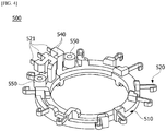
- FIG. 4 is a view illustrating the busbar including a guide
- FIG. 5 is a view illustrating the busbar including a hole as the first coupling part.
- the busbar body 510 may include holes 530 as the first coupling part.
- the holes 530 are disposed between guides 540.
- the holes 530 correspond to spaces between the guides 540.
- the holes 530 are disposed in the shaft direction.
- the guides 540 extend upward from an upper surface of the busbar body 510 and are disposed to surround one portions of the first end portions 521 to correspond to shapes of the first end portions 521 of the first terminals 520. Ends of the first end portions 521 are exposed to be connected to the second end portions 621.
- the holes 530 may be disposed between the first end portions 521 in a circumferential direction based on a center C of the busbar 500. For example, three first end portions 521 may be disposed, and one hole 530 may be disposed between two first end portions 521 so that a total of two holes 530 may be disposed between three first end portions 521.
- FIG. 6 is a view illustrating the guide.
- the guides 540 may include first parts 541 and the second parts 542.
- the first parts 541 may protrude from the upper surface of the busbar body 510.
- the second parts 542 may be bent from the first parts 541 and extend outward in a radial direction of the busbar 500.
- the second coupling part of the terminal body 610 is fitted into the hole 530 formed between the second parts 542 to be disposed in the hole 530.
- the busbar body 510 may include the third coupling part.
- the busbar body 510 may include first bosses 550 including coupling holes as the third coupling part.
- the first bosses 550 may be disposed at both sides of the guides 540.
- the first bosses 550 may protrude from the upper surface of the busbar body 510.
- FIG. 7 is a view illustrating the terminal portion
- FIG. 8 is a view illustrating a lower surface of the terminal portion of FIG. 7 .
- the terminal portion 600 may include the terminal body 610 and the second terminals 620.
- the terminal body 610 may be formed to extend in a longitudinal direction.
- the second terminals 620 are disposed on the terminal body 610.
- the second terminals 620 may be formed to extend in the longitudinal direction. Ends of the second end portions 621 of the second terminals 620 are exposed at the outside of the terminal body 610. This is to be connected to the first end portions 521.
- the terminal body 610 includes protrusions 630 which are the fourth coupling part.
- the protrusions 630 are disposed in a groove 640.
- the groove 640 is disposed in a lower end portion of the terminal body 610.
- the groove 640 is fitted to the guide 540 of the busbar body 510.
- the plurality of protrusions 630 may be provided.
- the number of the protrusions 630 may correspond to the number of holes 530.
- the protrusions 630 may be fitted to the holes 530 of the busbar body 510.
- FIG. 9 is a view illustrating the second end portion of the second terminal and the groove and the protrusion of the terminal body.
- the protrusions 630 may be disposed between the second end portions 621 in the circumferential direction.
- the protrusions 630 may be disposed between the first end portions 521.
- the grooves 640 may be disposed between the second end portions 621 in the circumferential direction.
- the terminal body 610 may include the fourth coupling part.
- the terminal body 610 may include second bosses 650 including coupling holes as the fourth coupling part.
- the second bosses 650 may be disposed at both sides of the groove 640.
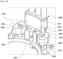
- FIG. 10 is a view illustrating a coupling state of the busbar and the terminal portion.
- the busbar body 510 is fitted to the terminal body 610 in the shaft direction.
- the protrusions 630 enter the holes 530 between the guides 540.
- the busbar body 510 and the terminal body 610 are individual components, since the busbar body 510 is fitted to the terminal body 610, assembly thereof is easy.
- the protrusions 630 are fitted thereto along sidewalls of the guides 540 including the first end portions 521, there is an advantage in that a position arrangement of the second terminals 620 is facilitated.
- the holes 530 are disposed between the first end portions 521 and the protrusions 630 are disposed between the second end portions 621, there is an advantage in that the plurality of first end portions 521 are accurately in contact with the plurality of second end portions 621.
- the coupling hole of the first boss 550 and the coupling hole of the second boss 650 are aligned.
- the first boss 550 and the second boss 650 are coupled using the coupling member 700 such as a bolt.
- the first boss 550 is coupled to the second boss 650 to increase a coupling force of the busbar 500 and the terminal portion 600.
- the coupling of the first boss 550 and the second boss 650 improves structural stability of the terminal portion 600 and is advantageous for arranging positions thereof.
- FIG. 11 is a perspective view illustrating a busbar and a terminal portion of a motor according to another embodiment
- FIG. 12 is an exploded perspective view illustrating the motor illustrated in FIG. 11
- FIG. 13 is a side view illustrating the busbar and the terminal portion illustrated in FIG. 11
- FIG. 14 is a perspective view illustrating a fusing portion of a terminal end and a second terminal.
- a plurality of third terminals 1411 are provided.
- the plurality of third terminals 1411 may be disposed in a shaft direction.
- three third terminals 1411 may be disposed.
- lengths of the three third terminals 1411 may be the same or different.
- the lengths of the third terminals 1411 disposed on both sides thereof may be the same in the shaft direction.
- the length of the third terminal 1411 disposed at a center thereof may be longer than the lengths of the third terminals 1411 disposed at both sides thereof in the shaft direction.
- the length of the third terminal 1411 may be 100 mm to 130 mm.
- the third terminals 1411 may include terminal ends 4111 and insulating members 4112.
- the terminal ends 4111 may be disposed in the shaft direction.
- the terminal ends 4111 may be connected to a power source with a U-phase, a V-phase, and a W-phase.
- the other sides of the terminal ends 4111 may be connected to fourth terminals 1412.
- the terminal end 4111 may be formed in a rod shape of which a cross section is quadrilateral shape.
- An outer surface of the terminal end 4111 may include a plurality of flat surfaces.
- fusing portions 4111f fused to the fourth terminals 1412 may be formed on a lower side surface of the terminal ends 4111.
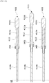
- FIG. 15 is a cross-sectional view illustrating the terminal end and an insulating member
- FIG. 16 is a perspective view illustrating the terminal end
- FIG. 17 is a cross-sectional view illustrating the terminal end.
- the terminal ends 4111 may include first regions 4111a, second regions 4111b, and third regions 4111c.
- the first regions 4111a are in contact with the insulating members 4112. In this case, the first regions 4111a and the insulating members 4112 may be coupled in an insert-injection manner.
- the second regions 4111b extend from the first regions 4111a in a direction toward one side. In this case, widths of the first regions 4111a may be greater than widths of the second regions 4111b. In addition, the second regions 4111b pass through a terminal body 1422. In this case, end portions of the second regions 4111b may be exposed from a second body 422. In addition, the fusing portions 4111f may be formed on the end portions of the second regions 4111b. In this case, a length of at least one second region 4111b may be different from a length of another adjacent second region 4111b. That is, heights of end portions of the third terminals 1411 may be different from each other to correspond to a difference ⁇ d in length between at least one second region 4111b and another adjacent second region 4111b.
- the regions 4111c extend from the first regions 4111a in a direction toward the other side.
- the third regions 4111c are connected to a power source with the U-phase, the V-phase, and the W-phase. In this case, widths of the third regions 4111c may be greater than widths of the first regions 4111a.
- each of the terminal ends 4111 may include at least one first stepped portion 4111s.
- the terminal end 4111 may include the stepped portion 4111s on a side surface thereof.
- a protruding region is formed at a central portion of the terminal end 4111 so that the stepped portion 4111s may be formed.
- a stress is concentrated at the stepped portion 4111s, and flatness can be improved.
- the insulating members 4112 surround one portions of the terminal ends 4111.
- the insulating members 4112 may be in contact with the first regions 4111a.
- the insulating members 4112 may be integrally formed with the terminal ends 4111 in an insert-injection manner.
- the plurality of insulating members 4112 may be formed.
- three insulating members 4112 may be formed to correspond to the number of terminal ends.
- the insulating members 4112 may be coupled to the terminal body 1422. In this case, the insulating members 4112 may be disposed on the terminal body 1422 in the shaft direction.
- the fourth terminals 1412 are disposed under the third terminals 1411.
- the fourth terminals 1412 may be connected to coils 330.
- the plurality of fourth terminals 1412 may be provided.
- three fourth terminals 1412 may be formed.
- Three fourth terminals 1412 may be disposed in an annular shape.
- the fourth terminals 1412 may be in contact with end portions of the terminal ends 4111.
- Second fusing portions 412f fused to the terminal ends 4111 may be formed at one sides of the plurality of fourth terminals 1412.
- FIG. 18 is a cross-sectional view illustrating a coupling state of a first tube and the insulating member
- FIG. 19 is a side view illustrating a neck and the terminal body
- FIG. 20 is a side view illustrating a busbar body and the terminal body.
- the motor may include a busbar body 1421, the terminal body 1422, a neck 1424, and sealing members 1425.
- the busbar body 1421 is disposed on a stator 300.
- the busbar body 1421 is formed in an annular shape.
- the plurality of fourth terminals 1412 are disposed in the busbar body 1421.
- the busbar body 1421 is connected to the terminal body 1422.
- the terminal body 1422 is disposed on the busbar body 1421 in the shaft direction.
- the terminal body 1422 may include a plurality of first tubes.
- the plurality of first tubes 4221 may include hollow portions, and terminal ends 4111 may pass through the hollow portions.
- the end portions of the terminal ends 4111 may be disposed under lower ends of the first tubes 4221 so that the end portions of the terminal ends 4111 may be exposed.
- the insulating members 4112 are coupled to upper ends of the first tubes 4221.
- end portions of the insulating members 4112 may be inserted into end portions of the first tubes 4221.
- a diameter of the insulating member 4112 may decrease in a direction toward the end portion thereof.
- End steps 4112s may be formed on the insulating members 4112 to be spaced apart from the end portions of the insulating members 4112 by a predetermined length. In this case, the insulating members 4112 may be restricted from being inserted into the first tubes 4221 due to the end steps 4112s.
- the insulating members 4112 and the first tubes 4221 are separable from each other. That is, the insulating members 4112 and the first tubes 4221 are provided as individual components. As described above, since the first tubes 4221 and the insulating members 4112 disposed to correspond to the lengths of the terminal ends 4111 in the shaft direction are formed in the separable structure, there are advantages in that position accuracy of the terminal ends 4111 in the busbar body 1421 can be improved, and dimension management thereof is facilitated.
- the neck 1424 is disposed on the busbar body 1421.
- the neck 1424 connects the busbar body 1421 and the terminal body 1422.
- the busbar body 1421, the terminal body 1422, and the neck 1424 may be formed of the same material.
- the busbar body 1421, the terminal body 1422, and the neck 1424 may be integrally formed.
- the sealing members 1425 are disposed between the insulating members 4112 and the terminal body 1422. One end portions of the sealing members 1425 may be in contact with upper end portions of the first tubes 4221. In addition, the other end portions of the sealing members 1425 may be in contact with the end steps 4112s of the insulating members 4112. In addition, the sealing members 1425 may be disposed to surround lower end portions of the insulating members 4112.
- an upper end may be disposed outside a lower end in a radial direction.
- the neck 1424 may include a first member 4241 and a second member 4242.
- the second member 4242 may be connected to an upper surface of the busbar body 1421.
- the first member 4241 is connected to an upper portion of the second member 4242 and extends in an outer diagonal direction. Accordingly, the busbar body 1421 and the terminal body 1422 may be connected through the neck 1424 to not overlap in the shaft and radial directions.
- the busbar body 1421 and the terminal body 1422 do not overlap in the radial and shaft directions.
- a region A1 of the busbar body 1421 in the radial direction is disposed under the terminal body 1422.
- the region A1 of the terminal body 1422 in the shaft direction is disposed outside the busbar body 1421.
- FIG. 21 is a view illustrating a height of the end portion of the terminal end.
- a height of the end portion of the terminal end 4111 is a height from a lower surface of the busbar body 1421 to a lower surface of the terminal end 4111
- a height h1 of the end portion of at least one terminal end 4111 is different from a height h2 of the end portion of another adjacent terminal end 4111.
- a difference ⁇ h in height between the end portions of the terminal ends 4111 adjacent to each other corresponds to the difference ⁇ d in length between the second regions 4111b adjacent to each other described with reference to FIG. 5 .
- the heights of the fusing portions 4111f may be different by as much as the difference ⁇ h in height between the terminal ends 4111.
- connection structure of a terminal end and an insulating member of the present invention will be described with reference to FIGS. 22 and 23 .
- FIG. 22 is a cross-sectional view illustrating a second example of the terminal end and the insulating member
- FIG. 23 is a cross-sectional view illustrating a third example of the terminal end and the insulating member.
- Terminal ends 4113 or 4114 and insulating members 4115 or 4116 may be formed in a separate structure. In addition, the terminal ends 4113 or 4114 may be seated on the insulating members 4115 or second bodies 423.
- second stepped portions 4113s may be formed in first regions.
- supports 4115a which are in contact with the second stepped portions 4113s to support terminal ends 4113 may be formed in insulating members 4115.
- the support 4115a may have a protruding shape protruding in a direction from an inner circumferential surface of the insulating member 4115 to a center of the insulating member 4115.
- the terminal ends 4113 may be inserted into the insulating members 4115. In this case, the terminal ends 4113 may be inserted thereinto in a direction from a side opposite to a side of the support 4115a toward the side of the support 4115a.
- a length from an end portion of at least one terminal end 4113 to the second stepped portion 4113s may be different from a length from one end portion of another adjacent terminal end 4113 to the second stepped portion 4113s.
- a difference ⁇ d in length may correspond to the difference ⁇ h in height between the one end portions of the terminal ends 4111 described with reference to FIG. 21 .
- second stepped portions 4114s may be formed in second regions.
- supports 4231 in contact with the second stepped portions 4114s to support the terminal ends 4114 may be formed in the second bodies 423.
- the terminal ends 4113 and the coupled second bodies 423 may be inserted into insulating members 4116.
- the terminal end 4114 may be inserted thereinto in a direction from a side opposite to a side of the support 4231 to the side of the support 4231.
Landscapes
- Engineering & Computer Science (AREA)
- Power Engineering (AREA)
- Insulation, Fastening Of Motor, Generator Windings (AREA)
- Motor Or Generator Frames (AREA)
Abstract
Description
- The present invention relates to a motor.
- Electronic power steering (EPS) systems secure turning stability and provide a rapid restoring force so that drivers can travel safely. Such an EPS system controls driving of a steering shaft of a vehicle by driving a motor using an electronic control unit (ECU) according to driving conditions detected by a vehicle speed sensor, a torque angel sensor, a torque sensor, and the like.
- The motor incudes a stator and a rotor. The stator may include stator cores and coils wound around teeth of the stator core. The stator may include the plurality of stator cores. In addition, the coils may be wound around the stator cores.
- The divided coils are connected by a busbar. The busbar is connected to a terminal portion connected to an external power source. The busbar and the terminal portion may be integrally designed. However, when a length of the terminal portion is long, there are problems in that it is difficult to form the terminal portion through an injection molding process, and it is difficult to arrange a position of the terminal portion. In addition, when a terminal of the busbar and a terminal of the terminal portion are integrally formed, there is a problem in that a large number of scraps are generated in a process in which the terminals are formed.
- In addition, the terminal portion is extended longer in a shaft direction. Accordingly, a problem occurs in that the terminal portion is bent or position accuracy of the terminal portion is insufficient.
- In addition, in a process in which the terminal of the terminal portion and the terminal of the busbar are fused, there are problems in that workability is degraded because a fusing space is insufficiently secured, and fusing quality is degraded due to interference between components.
- The present invention is directed to providing a motor which allows a position arrangement of a terminal portion connected to a busbar to be facilitated, and a number of scraps to be decreased when a terminal is manufactured.
- The present invention is also directed to providing a motor of which position accuracy of a terminal portion is to be improved and fusing quality of a terminal is improved.
- Objectives to be solved by the present invention are not limited to the above-described objectives, and other objectives which are not described above will be clearly understood by those skilled in the art from the following specification.
- One aspect of the present invention provides a motor including a housing, a stator disposed in the housing, a rotor disposed in the stator, a shaft coupled to the rotor, a busbar disposed above the stator, and a terminal portion connected to the busbar, wherein the busbar includes a busbar body and a plurality of first terminals disposed on the busbar body, the terminal portion includes a terminal body and second terminals disposed on the terminal body, first end portions of the first terminals are in contact with second end portions of the second terminals, the busbar body includes a first coupling part, the terminal body includes a second coupling part, the first coupling part is disposed between the first end portions, and the second coupling part is disposed between the second end portions.
- The first coupling part and the second coupling part may be disposed to overlap in a circumferential direction based on the shaft.
- The busbar may include a plurality of guides which extend upward from an upper surface of the busbar body and surround one portions of the first terminals, the plurality of guides may be disposed to be spaced apart from each other in the circumferential direction, and the first coupling part may include a hole formed by the plurality of guides disposed to be spaced apart from each other.
- The terminal portion may include a protrusion extending downward from a lower surface of the terminal body, and the second coupling part may be the protrusion.
- The busbar body may include a third coupling part, the terminal body may include a fourth coupling part, and the third coupling part may be coupled to the fourth coupling part using a coupling member.
- Another aspect of the present invention provides a motor including a housing, a stator disposed in the housing, a rotor disposed in the stator, a shaft coupled to the rotor, a busbar disposed above the stator, and a terminal portion connected to the busbar, wherein the busbar includes a busbar body and a plurality of first terminals disposed on the busbar body, the terminal portion includes a terminal body and a plurality of second terminals disposed on the terminal body, first end portions of the first terminals are in contact with second end portions of the second terminals, and the busbar body is fitted to the terminal body in a shaft direction.
- The busbar may include first bosses disposed at both sides of the first end portion and protruding upward from an upper surface of the busbar body, the terminal portion may include second bosses disposed at both sides of the second end portion and extending from the terminal body in a circumferential direction, and the first bosses and the second bosses may overlap in a shaft direction.
- The first bosses and the second bosses may incudes coupling holes and may further include coupling members disposed in the coupling holes to couple the first bosses and the second bosses.
- Still another aspect of the present invention provides a motor including a stator, a rotor disposed in the stator, a shaft coupled to the rotor, a busbar disposed above the stator, and a terminal portion connected to the busbar, wherein the terminal portion includes a terminal body and third terminals disposed on the terminal body, the busbar includes a busbar body and a plurality of fourth terminals disposed on the busbar body, at least one of the plurality of third terminals includes terminal ends and insulating members surrounding one portions of the terminal ends, the terminal ends pass through the terminal body, and the insulating members are coupled to the terminal body.
- A height of an end portion of the at least one third terminal may be different from a height of an end portion of another adjacent third terminal.
- The plurality of third terminals may include fusing portions fused to the plurality of fourth terminals, and heights of the fusing portions which are adjacent to each other may be different.
- A side surface of the terminal end may be a flat surface, and the fusing portion may be formed on a lower side surface of the terminal end.
- The plurality of third terminals may include first stepped portions on side surfaces.
- The number of the plurality of third terminals may be three, lengths of the third terminals disposed at both sides thereof may be the same in a shaft direction, and a length of the third terminal disposed at a center thereof may be longer than the lengths of the third terminals disposed at the both sides thereof in the shaft direction.
- The terminal ends may include first regions in contact with the insulating members, second regions which extend from the first regions and of which end portions are used to the fourth terminals, and lengths of the second regions which are adjacent to each other are different in the shaft direction.
- A width of one portion of the first region may be greater than a width of one portion of the second region.
- A second stepped portion may be formed in the first region or the second region, and the terminal body or the insulating member may include a support which is in contact with the second stepped portion to support the third terminal.
- The busbar body may include a neck connecting the busbar body and the terminal body.
- The terminal body may not overlap the busbar body in the shaft direction.
- The terminal body may not overlap the busbar body in a radial direction.
- A material of the terminal body may be the same as a material of the insulating member.
- The busbar body may further include a sealing member disposed between the terminal body and the insulating member.
- According to embodiments, advantageous effects in that a position arrangement of a terminal portion is facilitated and the terminal portion can be disposed accurately are provided.
- Since a terminal of a busbar and a terminal of the terminal portion are individually molded, an advantageous effect of significantly reducing a number of scraps is provided when the terminal is manufactured.
- An advantageous effect of facilitating assembly of the busbar and the terminal portion is provided.
- An advantageous effect in that a coupling force of the busbar and the terminal portion is high is provided.
- Since a busbar body and an insulating member are individually formed, position accuracy of terminal ends can be improved, and this is advantageous for managing dimensions of the busbar.
- There is an advantage in that a number of scraps can be reduced when a pressing process of the busbar body is performed.
- Since a fusing structure of the terminal end is improved, a space for a fusing operation between the terminal ends is secured, and thus workability can be improved, and fusing quality of the busbar can be improved.
-
-
FIG. 1 is a view illustrating a motor according to an embodiment. -
FIG. 2 is a view illustrating a busbar and a terminal portion. -
FIG. 3 is a view illustrating a terminal of the busbar. -
FIG. 4 is a view illustrating the busbar including a guide. -
FIG. 5 is a view illustrating the busbar including a hole as a first coupling part. -
FIG. 6 is a view illustrating a guide. -
FIG. 7 is a view illustrating the terminal portion. -
FIG. 8 is a view illustrating a lower surface of the terminal portion ofFIG. 7 . -
FIG. 9 is a view illustrating a second end portion of a second terminal and a groove and a protrusion of a terminal body. -
FIG. 10 is a view illustrating a coupling state of the busbar and the terminal portion. -
FIG. 11 is a perspective view illustrating a busbar and a terminal portion of a motor according to another embodiment. -
FIG. 12 is an exploded perspective view illustrating the motor illustrated inFIG. 11 . -
FIG. 13 is a side view illustrating the busbar and the terminal portion illustrated inFIG. 11 . -
FIG. 14 is a perspective view illustrating a fusing portion of a terminal end and a second terminal. -
FIG. 15 is a cross-sectional view illustrating the terminal end and an insulating member. -
FIG. 16 is a perspective view illustrating the terminal end. -
FIG. 17 is a cross-sectional view illustrating the terminal end. -
FIG. 18 is a cross-sectional view illustrating a coupling state of a first tube and the insulating member. -
FIG. 19 is a side view illustrating a neck and a terminal body. -
FIG. 20 is a side view illustrating a busbar body and the terminal body. -
FIG. 21 is a view illustrating a height of an end portion of the terminal end. -
FIG. 22 is a cross-sectional view illustrating a second example of the terminal end and the insulating member. -
FIG. 23 is a cross-sectional view illustrating a third example of the terminal end and the insulating member. - Hereinafter, exemplary embodiments of the present invention will be described in detail with reference to the accompanying drawings.
- However, the technical spirit of the present invention is not limited to some embodiments which will be described and may be realized using various other embodiments, and at least one component of the embodiments may be selectively coupled, substituted, and used to realize the technical spirit within the range of the technical spirit.
- In addition, unless clearly and specifically defined otherwise by context, all terms (including technical and scientific terms) used herein can be interpreted as having customary meanings to those skilled in the art, and meanings of generally used terms, such as those defined in commonly used dictionaries, will be interpreted by considering contextual meanings of the related technology.
- In addition, the terms used in the embodiments of the present invention are considered in a descriptive sense and not for limiting the present invention.
- In the present specification, unless clearly indicated otherwise by the context, singular forms include the plural forms thereof, and in a case in which "at least one (or one or more) among A, B, and C" is described, this may include at least one combination among all possible combinations of A, B, and C.
- In addition, in descriptions of components of the present invention, terms such as "first," "second," "A," "B," "(a)," and "(b)" can be used.
- The terms are only to distinguish one element from another element, and an essence, order, and the like of the element are not limited by the terms.
- In addition, it should be understood that, when an element is referred to as being "connected or coupled" to another element, such a description may include both of a case in which the element is directly connected or coupled to another element and a case in which the element is connected or coupled to another element with still another element disposed therebetween.
- In addition, in a case in which any one element is described as being formed or disposed "on or under" another element, such a description includes both a case in which the two elements are formed or disposed in direct contact with each other and a case in which one or more other elements are interposed between the two elements. In addition, when one element is described as being disposed "on or under" another element, such a description may include a case in which the one element is disposed at an upper side or a lower side with respect to another element.
-
FIG. 1 is a view illustrating a motor according to an embodiment. Referring toFIG. 1 , the motor according to the embodiment may include ahousing 400, ashaft 100, arotor 200, and astator 300. Thestator 300 is disposed in thehousing 400, therotor 200 is disposed in thestator 300, and therotor 200 is disposed outside theshaft 100. In this case, the term "inside" refers to a direction toward theshaft 100 of the motor, and the term "outside" refers to a direction from theshaft 100 toward thehousing 400, which is opposite to the term "inside." - The
shaft 100 may be coupled to therotor 200. When a current is supplied, an electrical interaction occurs between therotor 200 and thestator 300, therotor 200 is rotated, and theshaft 100 is rotated in conjunction with the rotation of therotor 200. Theshaft 100 may be connected to a steering apparatus of a vehicle to transmit power to the steering apparatus. - The
rotor 200 is rotated due to the electrical interaction with thestator 300. - The
rotor 200 may be disposed inside thestator 300. Therotor 200 may include a rotor core and magnets disposed on the rotor core. - The
stator 300 is disposed outside therotor 200. Thestator 300 may include astator core 310,insulators 320, and coils 330. Theinsulators 320 are installed on thestator core 310. Thecoils 330 are wound around theinsulators 320. The coils induce an electrical interaction with the magnets of therotor 200. - The
rotor 200 and thestator 300 are accommodated in thehousing 400. - A
busbar 500 is disposed above thestator 300. Thebusbar 500 connects the coils to thestator 300. - Terminal portions 600 (see
FIG. 2 ) are connected to thebusbar 500. In addition, theterminal portion 600 is connected to an external power source. -
FIG. 2 is a view illustrating the busbar and the terminal portion.FIG. 3 is a view illustrating a terminal of the busbar. - Referring to
FIG. 2 , thebusbar 500 may include abusbar body 510 andfirst terminals 520. Thebusbar body 510 may be a member having an annular shape. Thefirst terminals 520 are disposed on thebusbar body 510. Thefirst terminals 520 may be phase terminals. - The
terminal portions 600 may includeterminal bodies 610 andsecond terminals 620 disposed on theterminal bodies 610. - Referring to
FIGS. 2 and3 , the plurality offirst terminals 520 may be provided and threefirst terminals 520 may be formed to implement a U-phase, a V-phase, and a W-phase. In this case, thefirst terminals 520 may includefirst end portions 521. In this case, thefirst end portions 521 refer to end portions of thefirst terminals 520 extending in a radial direction to be in contact with thesecond terminals 620. In addition, threesecond terminals 620 may also be formed to apply power with the U-phase, the V-phase, and the W-phase to correspond to thefirst terminals 520, and thesecond terminals 620 may includesecond end portions 621. Thesecond end portions 621 refer to end portions of thesecond terminals 620 in contact with thefirst end portions 521. - The
busbar 500 and theterminal portion 600 may be assembled by coupling a first coupling part and a second coupling part. - In addition, the
busbar 500 and theterminal portion 600 may be coupled by coupling a third coupling part and a fourth coupling part. The first coupling part may be fitted to the second coupling part in a shaft direction. The third coupling part may be coupled to the fourth coupling part using acoupling member 700. -
FIG. 4 is a view illustrating the busbar including a guide, andFIG. 5 is a view illustrating the busbar including a hole as the first coupling part. - Referring to
FIGS. 4 and5 , thebusbar body 510 may includeholes 530 as the first coupling part. Theholes 530 are disposed betweenguides 540. Theholes 530 correspond to spaces between theguides 540. Theholes 530 are disposed in the shaft direction. Theguides 540 extend upward from an upper surface of thebusbar body 510 and are disposed to surround one portions of thefirst end portions 521 to correspond to shapes of thefirst end portions 521 of thefirst terminals 520. Ends of thefirst end portions 521 are exposed to be connected to thesecond end portions 621. - The
holes 530 may be disposed between thefirst end portions 521 in a circumferential direction based on a center C of thebusbar 500. For example, threefirst end portions 521 may be disposed, and onehole 530 may be disposed between twofirst end portions 521 so that a total of twoholes 530 may be disposed between threefirst end portions 521. -
FIG. 6 is a view illustrating the guide. - Referring to
FIG. 6 , theguides 540 may includefirst parts 541 and thesecond parts 542. Thefirst parts 541 may protrude from the upper surface of thebusbar body 510. Thesecond parts 542 may be bent from thefirst parts 541 and extend outward in a radial direction of thebusbar 500. The second coupling part of theterminal body 610 is fitted into thehole 530 formed between thesecond parts 542 to be disposed in thehole 530. Thebusbar body 510 may include the third coupling part. Thebusbar body 510 may includefirst bosses 550 including coupling holes as the third coupling part. Thefirst bosses 550 may be disposed at both sides of theguides 540. Thefirst bosses 550 may protrude from the upper surface of thebusbar body 510. -
FIG. 7 is a view illustrating the terminal portion, andFIG. 8 is a view illustrating a lower surface of the terminal portion ofFIG. 7 . - Referring to
FIGS. 7 and8 , theterminal portion 600 may include theterminal body 610 and thesecond terminals 620. Theterminal body 610 may be formed to extend in a longitudinal direction. Thesecond terminals 620 are disposed on theterminal body 610. Thesecond terminals 620 may be formed to extend in the longitudinal direction. Ends of thesecond end portions 621 of thesecond terminals 620 are exposed at the outside of theterminal body 610. This is to be connected to thefirst end portions 521. - The
terminal body 610 includesprotrusions 630 which are the fourth coupling part. Theprotrusions 630 are disposed in agroove 640. Thegroove 640 is disposed in a lower end portion of theterminal body 610. Thegroove 640 is fitted to theguide 540 of thebusbar body 510. The plurality ofprotrusions 630 may be provided. The number of theprotrusions 630 may correspond to the number ofholes 530. Theprotrusions 630 may be fitted to theholes 530 of thebusbar body 510. -
FIG. 9 is a view illustrating the second end portion of the second terminal and the groove and the protrusion of the terminal body. - Referring to
FIGS. 5 and9 , theprotrusions 630 may be disposed between thesecond end portions 621 in the circumferential direction. In addition, in a state in which thebusbar body 510 and theterminal body 610 are coupled, theprotrusions 630 may be disposed between thefirst end portions 521. In addition, in the state in which thebusbar body 510 and theterminal body 610 are coupled, thegrooves 640 may be disposed between thesecond end portions 621 in the circumferential direction. - When the
protrusions 630 are fitted to theholes 530 of thebusbar body 510, theprotrusions 630 and thegroove 640 overlap in the circumferential direction. In addition, when theprotrusions 630 are fitted to theholes 530 of thebusbar body 510, thesecond end portions 621 are in contact with thefirst end portions 521. Theterminal body 610 may include the fourth coupling part. Theterminal body 610 may includesecond bosses 650 including coupling holes as the fourth coupling part. Thesecond bosses 650 may be disposed at both sides of thegroove 640. -
FIG. 10 is a view illustrating a coupling state of the busbar and the terminal portion. - Referring to
FIGS. 5 ,9 , and10 , thebusbar body 510 is fitted to theterminal body 610 in the shaft direction. Theprotrusions 630 enter theholes 530 between theguides 540. Although thebusbar body 510 and theterminal body 610 are individual components, since thebusbar body 510 is fitted to theterminal body 610, assembly thereof is easy. In addition, since theprotrusions 630 are fitted thereto along sidewalls of theguides 540 including thefirst end portions 521, there is an advantage in that a position arrangement of thesecond terminals 620 is facilitated. Particularly, since theholes 530 are disposed between thefirst end portions 521 and theprotrusions 630 are disposed between thesecond end portions 621, there is an advantage in that the plurality offirst end portions 521 are accurately in contact with the plurality ofsecond end portions 621. - In the state in which the
protrusion 630 is inserted into thehole 530, the coupling hole of thefirst boss 550 and the coupling hole of thesecond boss 650 are aligned. Thefirst boss 550 and thesecond boss 650 are coupled using thecoupling member 700 such as a bolt. Thefirst boss 550 is coupled to thesecond boss 650 to increase a coupling force of thebusbar 500 and theterminal portion 600. When it is considered that theterminal portion 600 is disposed to extend in the shaft direction, the coupling of thefirst boss 550 and thesecond boss 650 improves structural stability of theterminal portion 600 and is advantageous for arranging positions thereof. -
FIG. 11 is a perspective view illustrating a busbar and a terminal portion of a motor according to another embodiment,FIG. 12 is an exploded perspective view illustrating the motor illustrated inFIG. 11 ,FIG. 13 is a side view illustrating the busbar and the terminal portion illustrated inFIG. 11 , andFIG. 14 is a perspective view illustrating a fusing portion of a terminal end and a second terminal. - Referring to
FIGS. 11 and12 , a plurality ofthird terminals 1411 are provided. The plurality ofthird terminals 1411 may be disposed in a shaft direction. For example, threethird terminals 1411 may be disposed. In this case, lengths of the threethird terminals 1411 may be the same or different. The lengths of thethird terminals 1411 disposed on both sides thereof may be the same in the shaft direction. However, the length of the third terminal 1411 disposed at a center thereof may be longer than the lengths of thethird terminals 1411 disposed at both sides thereof in the shaft direction. In this case, the length of the third terminal 1411 may be 100 mm to 130 mm. - Referring to
FIGS. 12 to 14 , thethird terminals 1411 may include terminal ends 4111 and insulatingmembers 4112. - The terminal ends 4111 may be disposed in the shaft direction. In this case, the terminal ends 4111 may be connected to a power source with a U-phase, a V-phase, and a W-phase. In addition, the other sides of the terminal ends 4111 may be connected to
fourth terminals 1412. In addition, theterminal end 4111 may be formed in a rod shape of which a cross section is quadrilateral shape. An outer surface of theterminal end 4111 may include a plurality of flat surfaces. In this case, fusingportions 4111f fused to thefourth terminals 1412 may be formed on a lower side surface of the terminal ends 4111. -
FIG. 15 is a cross-sectional view illustrating the terminal end and an insulating member,FIG. 16 is a perspective view illustrating the terminal end, andFIG. 17 is a cross-sectional view illustrating the terminal end. - Referring to
FIG. 15 , the terminal ends 4111 may includefirst regions 4111a,second regions 4111b, andthird regions 4111c. - The
first regions 4111a are in contact with the insulatingmembers 4112. In this case, thefirst regions 4111a and the insulatingmembers 4112 may be coupled in an insert-injection manner. - The
second regions 4111b extend from thefirst regions 4111a in a direction toward one side. In this case, widths of thefirst regions 4111a may be greater than widths of thesecond regions 4111b. In addition, thesecond regions 4111b pass through aterminal body 1422. In this case, end portions of thesecond regions 4111b may be exposed from a second body 422. In addition, the fusingportions 4111f may be formed on the end portions of thesecond regions 4111b. In this case, a length of at least onesecond region 4111b may be different from a length of another adjacentsecond region 4111b. That is, heights of end portions of thethird terminals 1411 may be different from each other to correspond to a difference Δd in length between at least onesecond region 4111b and another adjacentsecond region 4111b. - The
regions 4111c extend from thefirst regions 4111a in a direction toward the other side. Thethird regions 4111c are connected to a power source with the U-phase, the V-phase, and the W-phase. In this case, widths of thethird regions 4111c may be greater than widths of thefirst regions 4111a. - Referring to
FIGS. 16 and17 , each of the terminal ends 4111 may include at least one first steppedportion 4111s. In this case, theterminal end 4111 may include the steppedportion 4111s on a side surface thereof. In this case, a protruding region is formed at a central portion of theterminal end 4111 so that the steppedportion 4111s may be formed. In theterminal end 4111, a stress is concentrated at the steppedportion 4111s, and flatness can be improved. - Referring to
FIG. 15 , the insulatingmembers 4112 surround one portions of the terminal ends 4111. In this case, the insulatingmembers 4112 may be in contact with thefirst regions 4111a. The insulatingmembers 4112 may be integrally formed with the terminal ends 4111 in an insert-injection manner. In this case, the plurality of insulatingmembers 4112 may be formed. For example, three insulatingmembers 4112 may be formed to correspond to the number of terminal ends. In addition, the insulatingmembers 4112 may be coupled to theterminal body 1422. In this case, the insulatingmembers 4112 may be disposed on theterminal body 1422 in the shaft direction. - The
fourth terminals 1412 are disposed under thethird terminals 1411. In this case, thefourth terminals 1412 may be connected to coils 330. The plurality offourth terminals 1412 may be provided. For example, threefourth terminals 1412 may be formed. Threefourth terminals 1412 may be disposed in an annular shape. In this case, thefourth terminals 1412 may be in contact with end portions of the terminal ends 4111. Second fusing portions 412f fused to the terminal ends 4111 may be formed at one sides of the plurality offourth terminals 1412. -
FIG. 18 is a cross-sectional view illustrating a coupling state of a first tube and the insulating member,FIG. 19 is a side view illustrating a neck and the terminal body, andFIG. 20 is a side view illustrating a busbar body and the terminal body. - Referring to
FIG. 13 , the motor may include abusbar body 1421, theterminal body 1422, aneck 1424, and sealingmembers 1425. - The
busbar body 1421 is disposed on astator 300. Thebusbar body 1421 is formed in an annular shape. The plurality offourth terminals 1412 are disposed in thebusbar body 1421. Thebusbar body 1421 is connected to theterminal body 1422. - The
terminal body 1422 is disposed on thebusbar body 1421 in the shaft direction. Theterminal body 1422 may include a plurality of first tubes. The plurality offirst tubes 4221 may include hollow portions, and terminal ends 4111 may pass through the hollow portions. In this case, the end portions of the terminal ends 4111 may be disposed under lower ends of thefirst tubes 4221 so that the end portions of the terminal ends 4111 may be exposed. In addition, the insulatingmembers 4112 are coupled to upper ends of thefirst tubes 4221. - Referring to
FIGS. 12 and18 , end portions of the insulatingmembers 4112 may be inserted into end portions of thefirst tubes 4221. In this case, a diameter of the insulatingmember 4112 may decrease in a direction toward the end portion thereof.End steps 4112s may be formed on the insulatingmembers 4112 to be spaced apart from the end portions of the insulatingmembers 4112 by a predetermined length. In this case, the insulatingmembers 4112 may be restricted from being inserted into thefirst tubes 4221 due to the end steps 4112s. - The insulating
members 4112 and thefirst tubes 4221 are separable from each other. That is, the insulatingmembers 4112 and thefirst tubes 4221 are provided as individual components. As described above, since thefirst tubes 4221 and the insulatingmembers 4112 disposed to correspond to the lengths of the terminal ends 4111 in the shaft direction are formed in the separable structure, there are advantages in that position accuracy of the terminal ends 4111 in thebusbar body 1421 can be improved, and dimension management thereof is facilitated. - The
neck 1424 is disposed on thebusbar body 1421. In this case, theneck 1424 connects thebusbar body 1421 and theterminal body 1422. Thebusbar body 1421, theterminal body 1422, and theneck 1424 may be formed of the same material. Thebusbar body 1421, theterminal body 1422, and theneck 1424 may be integrally formed. - The sealing
members 1425 are disposed between the insulatingmembers 4112 and theterminal body 1422. One end portions of the sealingmembers 1425 may be in contact with upper end portions of thefirst tubes 4221. In addition, the other end portions of the sealingmembers 1425 may be in contact with the end steps 4112s of the insulatingmembers 4112. In addition, the sealingmembers 1425 may be disposed to surround lower end portions of the insulatingmembers 4112. - Referring to
FIGS. 19 and 20 , in theneck 1424, an upper end may be disposed outside a lower end in a radial direction. In addition, theneck 1424 may include afirst member 4241 and asecond member 4242. Thesecond member 4242 may be connected to an upper surface of thebusbar body 1421. In addition, thefirst member 4241 is connected to an upper portion of thesecond member 4242 and extends in an outer diagonal direction. Accordingly, thebusbar body 1421 and theterminal body 1422 may be connected through theneck 1424 to not overlap in the shaft and radial directions. - Referring to
FIG. 20 , thebusbar body 1421 and theterminal body 1422 do not overlap in the radial and shaft directions. In this case, a region A1 of thebusbar body 1421 in the radial direction is disposed under theterminal body 1422. In addition, the region A1 of theterminal body 1422 in the shaft direction is disposed outside thebusbar body 1421. As described above, since thebusbar body 1421 and theterminal body 1422 are disposed to not overlap as much as possible, a fusing space of the end portion of the third terminal 1411 positioned under thebusbar body 1421 may be secured sufficiently, and utilization of spaces between the components may be improved. -
FIG. 21 is a view illustrating a height of the end portion of the terminal end. - Referring to
FIG. 21 , when it is assumed that a height of the end portion of theterminal end 4111 is a height from a lower surface of thebusbar body 1421 to a lower surface of theterminal end 4111, a height h1 of the end portion of at least oneterminal end 4111 is different from a height h2 of the end portion of another adjacentterminal end 4111. In this case, a difference Δh in height between the end portions of the terminal ends 4111 adjacent to each other corresponds to the difference Δd in length between thesecond regions 4111b adjacent to each other described with reference toFIG. 5 . As described above, the heights of the fusingportions 4111f may be different by as much as the difference Δh in height between the terminal ends 4111. - As described above, since the difference Δh in height between the fusing
portions 4111f is generated, a space for a fusing operation of theterminal end 4111 and thefourth terminal 1412 is secured, and thus the fusing workability can be improved, and fusing quality of the busbar 1400 can be improved. - Hereinafter, another example of a connection structure of a terminal end and an insulating member of the present invention will be described with reference to
FIGS. 22 and23 . -
FIG. 22 is a cross-sectional view illustrating a second example of the terminal end and the insulating member, andFIG. 23 is a cross-sectional view illustrating a third example of the terminal end and the insulating member. - Terminal ends 4113 or 4114 and insulating
members members 4115 or second bodies 423. - Referring to
FIG. 22 , in the terminal ends 4113, second steppedportions 4113s may be formed in first regions. In addition, supports 4115a which are in contact with the second steppedportions 4113s to support terminal ends 4113 may be formed in insulatingmembers 4115. In this case, thesupport 4115a may have a protruding shape protruding in a direction from an inner circumferential surface of the insulatingmember 4115 to a center of the insulatingmember 4115. The terminal ends 4113 may be inserted into the insulatingmembers 4115. In this case, the terminal ends 4113 may be inserted thereinto in a direction from a side opposite to a side of thesupport 4115a toward the side of thesupport 4115a. In this case, a length from an end portion of at least oneterminal end 4113 to the second steppedportion 4113s may be different from a length from one end portion of another adjacentterminal end 4113 to the second steppedportion 4113s. In this case, a difference Δd in length may correspond to the difference Δh in height between the one end portions of the terminal ends 4111 described with reference toFIG. 21 . - Meanwhile, referring to
FIG. 23 , in the terminal ends 4114, second steppedportions 4114s may be formed in second regions. In addition, supports 4231 in contact with the second steppedportions 4114s to support the terminal ends 4114 may be formed in the second bodies 423. In this case, the terminal ends 4113 and the coupled second bodies 423 may be inserted into insulatingmembers 4116. In this case, theterminal end 4114 may be inserted thereinto in a direction from a side opposite to a side of thesupport 4231 to the side of thesupport 4231. - As described above, the motor according to one exemplary embodiment of the present invention has been specifically described with reference to the accompanying drawings.
- The above description is only an example describing a technological scope of the present invention. Various changes, modifications, and replacements may be made by those skilled in the art without departing from the spirit and scope of the present invention. Therefore, the embodiments disclosed above and in the accompanying drawings should be considered in a descriptive sense only and not to limit the technological scope. The technological scope of the present invention is not limited by the embodiments and the accompanying drawings. The scope of the present invention should be interpreted by the appended claims and encompass all equivalents falling within the scope of the appended claims.
Claims (10)
- A motor comprising:a housing;a stator disposed in the housing;a rotor disposed in the stator;a shaft coupled to the rotor;a busbar disposed above the stator; anda terminal portion connected to the busbar,wherein the busbar includes a busbar body and a plurality of first terminals disposed on the busbar body,the terminal portion includes a terminal body and second terminals disposed on the terminal body,first end portions of the first terminals are in contact with second end portions of the second terminals,the busbar body includes a first coupling part,the terminal body includes a second coupling part,the first coupling part is disposed between the first end portions, andthe second coupling part is disposed between the second end portions.
- The motor of claim 1, wherein the first coupling part and the second coupling part are disposed to overlap in a circumferential direction based on the shaft.
- The motor of claim 2, wherein:the busbar includes a plurality of guides which extend upward from an upper surface of the busbar body and surround one portions of the first terminals;the plurality of guides are disposed to be spaced apart from each other in the circumferential direction; andthe first coupling part includes a hole formed by the plurality of guides disposed to be spaced apart from each other.
- The motor of claim 3, wherein:the terminal portion includes a protrusion extending downward from a lower surface of the terminal body; andthe second coupling part includes the protrusion.
- A motor comprising:a housing;a stator disposed in the housing;a rotor disposed in the stator;a shaft coupled to the rotor;a busbar disposed above the stator; anda terminal portion connected to the busbar,wherein the busbar includes a busbar body and a plurality of first terminals disposed on the busbar body,the terminal portion includes a terminal body and a plurality of second terminals disposed on the terminal body,first end portions of the first terminals are in contact with second end portions of the second terminals, andthe busbar body is fitted to the terminal body in a shaft direction.
- A motor comprising:a stator;a rotor disposed in the stator;a shaft coupled to the rotor;a busbar disposed above the stator; anda terminal portion connected to the busbar,wherein the terminal portion includes a terminal body and third terminals disposed on the terminal body,the busbar includes a busbar body and a plurality of fourth terminals disposed on the busbar body,at least one of the plurality of third terminals includes terminal ends and insulating members surrounding one portions of the terminal ends,the terminal ends pass through the terminal body, andthe insulating members are coupled to the terminal body.
- The motor of claim 6, wherein a height of an end portion of the at least one third terminal is different from a height of an end portion of another adjacent third terminal.
- The motor of claim 6, wherein:the plurality of third terminals include fusing portions fused to the plurality of fourth terminals; andheights of the fusing portions which are adjacent to each other are different.
- The motor of claim 6, wherein:the number of the plurality of third terminals is three;lengths of the third terminals disposed at both sides thereof are the same in a shaft direction; anda length of the third terminal disposed at a center thereof is longer than the lengths of the third terminals disposed at the both sides thereof in the shaft direction.
- The motor of claim 6, wherein the terminal ends include:first regions in contact with the insulating members;second regions which extend from the first regions and of which end portions are fused to the fourth terminals; andlengths of the second regions which are adjacent to each other are different in the shaft direction.
Applications Claiming Priority (3)
| Application Number | Priority Date | Filing Date | Title |
|---|---|---|---|
| KR1020180126087A KR102755081B1 (en) | 2018-10-22 | 2018-10-22 | Motor |
| KR1020190080213A KR102802281B1 (en) | 2019-07-03 | 2019-07-03 | Motor |
| PCT/KR2019/013851 WO2020085744A1 (en) | 2018-10-22 | 2019-10-22 | Motor |
Publications (2)
| Publication Number | Publication Date |
|---|---|
| EP3872968A1 true EP3872968A1 (en) | 2021-09-01 |
| EP3872968A4 EP3872968A4 (en) | 2022-11-02 |
Family
ID=70331586
Family Applications (1)
| Application Number | Title | Priority Date | Filing Date |
|---|---|---|---|
| EP19876706.3A Pending EP3872968A4 (en) | 2018-10-22 | 2019-10-22 | ENGINE |
Country Status (5)
| Country | Link |
|---|---|
| US (1) | US12027947B2 (en) |
| EP (1) | EP3872968A4 (en) |
| JP (1) | JP7474267B2 (en) |
| CN (1) | CN113615052B (en) |
| WO (1) | WO2020085744A1 (en) |
Cited By (1)
| Publication number | Priority date | Publication date | Assignee | Title |
|---|---|---|---|---|
| WO2024074280A1 (en) * | 2022-10-07 | 2024-04-11 | Ampere S.A.S. | Device for electrical connection between an electric machine and a power electronics module |
Families Citing this family (2)
| Publication number | Priority date | Publication date | Assignee | Title |
|---|---|---|---|---|
| KR20210123916A (en) * | 2020-04-06 | 2021-10-14 | 엘지이노텍 주식회사 | Motor |
| CN115149686A (en) * | 2021-03-31 | 2022-10-04 | 日本电产株式会社 | Motor and electric product |
Family Cites Families (23)
| Publication number | Priority date | Publication date | Assignee | Title |
|---|---|---|---|---|
| JP2001095201A (en) | 1999-09-24 | 2001-04-06 | Toyoda Mach Works Ltd | Connecting method for motor |
| DE10232281A1 (en) * | 2002-07-16 | 2004-02-12 | Phoenix Contact Gmbh & Co. Kg | Electrical connection arrangement for connecting cable to external rotor motor's stator winding ends has plug strip contacts, conducting pieces, connecting elements in form of lead frame |
| JP4783012B2 (en) * | 2004-12-28 | 2011-09-28 | 日立オートモティブシステムズ株式会社 | Electric power steering motor and manufacturing method thereof |
| US7588444B2 (en) * | 2006-02-01 | 2009-09-15 | Nidec Corporation | Busbar unit, electric motor and electrohydraulic power steering system furnished with the busbar unit, and method of manufacturing the busbar unit |
| JP2008220061A (en) * | 2007-03-05 | 2008-09-18 | Asmo Co Ltd | Motor device |
| JP5212080B2 (en) * | 2008-12-19 | 2013-06-19 | 日本精工株式会社 | Electric power steering device |
| KR200456092Y1 (en) | 2010-03-02 | 2011-10-11 | 계양전기 주식회사 | Busbar device for brushless motor |
| EP2458715B1 (en) * | 2010-11-05 | 2014-01-08 | LG Innotek Co., Ltd. | Bus bar of EPS motor |
| JP2012110188A (en) * | 2010-11-19 | 2012-06-07 | Nippon Densan Corp | Intermediate connection member, stator, and motor |
| JP2013005705A (en) * | 2011-06-22 | 2013-01-07 | Kokusan Denki Co Ltd | Dc motor for pump |
| KR20130061283A (en) * | 2011-12-01 | 2013-06-11 | 엘지이노텍 주식회사 | Stator of eps motor |
| JP6073703B2 (en) * | 2013-02-22 | 2017-02-01 | 住友電装株式会社 | Centralized power distribution member of motor |
| JP5985046B2 (en) * | 2013-04-10 | 2016-09-06 | 三菱電機株式会社 | Motor stator |
| JP6264932B2 (en) * | 2014-02-20 | 2018-01-24 | 日本精工株式会社 | Brushless motor and electric power steering apparatus |
| KR102353916B1 (en) * | 2015-04-15 | 2022-01-21 | 엘지이노텍 주식회사 | Terminal asembly for motor and Motor using the same |
| WO2017026023A1 (en) * | 2015-08-10 | 2017-02-16 | 日本精工株式会社 | Brushless motor, and electric power steering device and vehicle in which said brushless motor is installed |
| WO2017026412A1 (en) * | 2015-08-10 | 2017-02-16 | 日本電産株式会社 | Motor |
| JP6358220B2 (en) * | 2015-10-07 | 2018-07-18 | トヨタ自動車株式会社 | Terminal block connection structure of rotating electrical machine |
| CN108141113B (en) * | 2015-11-06 | 2020-11-10 | 日本电产株式会社 | motor |
| KR102625432B1 (en) * | 2016-01-08 | 2024-01-16 | 엘지이노텍 주식회사 | Busbar terminal, busbar, motor and vehicle having the same |
| KR102667066B1 (en) * | 2016-03-02 | 2024-05-20 | 엘지이노텍 주식회사 | Busbar assembly and motor having the same |
| CN109478823B (en) * | 2016-07-20 | 2020-12-29 | 日本电产株式会社 | motor |
| CN109792183B (en) * | 2016-09-30 | 2021-12-28 | 日本电产株式会社 | Motor and electric power steering apparatus |
-
2019
- 2019-10-22 WO PCT/KR2019/013851 patent/WO2020085744A1/en not_active Ceased
- 2019-10-22 EP EP19876706.3A patent/EP3872968A4/en active Pending
- 2019-10-22 US US17/286,559 patent/US12027947B2/en active Active
- 2019-10-22 CN CN201980069555.2A patent/CN113615052B/en active Active
- 2019-10-22 JP JP2021547024A patent/JP7474267B2/en active Active
Cited By (2)
| Publication number | Priority date | Publication date | Assignee | Title |
|---|---|---|---|---|
| WO2024074280A1 (en) * | 2022-10-07 | 2024-04-11 | Ampere S.A.S. | Device for electrical connection between an electric machine and a power electronics module |
| FR3140718A1 (en) * | 2022-10-07 | 2024-04-12 | Renault | Electrical connection device between an electrical machine and a power electronics module |
Also Published As
| Publication number | Publication date |
|---|---|
| CN113615052B (en) | 2024-08-20 |
| EP3872968A4 (en) | 2022-11-02 |
| US12027947B2 (en) | 2024-07-02 |
| JP7474267B2 (en) | 2024-04-24 |
| WO2020085744A1 (en) | 2020-04-30 |
| US20210344251A1 (en) | 2021-11-04 |
| CN113615052A (en) | 2021-11-05 |
| JP2022508927A (en) | 2022-01-19 |
Similar Documents
| Publication | Publication Date | Title |
|---|---|---|
| EP2182615B1 (en) | Wiring component for motor coil | |
| US10903711B2 (en) | Motor | |
| EP2182614B1 (en) | Wiring component for motor coil | |
| US20210091624A1 (en) | Busbar, motor, and power transmission system using same | |
| EP1881584B1 (en) | Terminal for rotating armature | |
| US11228217B2 (en) | Bus bar assembly and motor | |
| KR102353916B1 (en) | Terminal asembly for motor and Motor using the same | |
| US20160336829A1 (en) | Rotary electric machine stator | |
| US20200014273A1 (en) | Stator, motor, and electric power steering device | |
| US12027947B2 (en) | Motor | |
| US11075558B2 (en) | Bus bar unit and motor | |
| EP3556532B1 (en) | Molded body | |
| JP7318654B2 (en) | motor | |
| US11901792B2 (en) | Bus bar unit, stator, and motor | |
| KR102802281B1 (en) | Motor | |
| CN114930693A (en) | Electrical machine | |
| CN113228467B (en) | Electric Motor | |
| JP5144180B2 (en) | Stator midpoint connection structure | |
| JP2001086695A (en) | Motor | |
| WO2019082709A1 (en) | Stator and motor | |
| CN113424406A (en) | Motor | |
| WO2016060015A1 (en) | Electric motor |
Legal Events
| Date | Code | Title | Description |
|---|---|---|---|
| STAA | Information on the status of an ep patent application or granted ep patent |
Free format text: STATUS: THE INTERNATIONAL PUBLICATION HAS BEEN MADE |
|
| PUAI | Public reference made under article 153(3) epc to a published international application that has entered the european phase |
Free format text: ORIGINAL CODE: 0009012 |
|
| STAA | Information on the status of an ep patent application or granted ep patent |
Free format text: STATUS: REQUEST FOR EXAMINATION WAS MADE |
|
| 17P | Request for examination filed |
Effective date: 20210416 |
|
| AK | Designated contracting states |
Kind code of ref document: A1 Designated state(s): AL AT BE BG CH CY CZ DE DK EE ES FI FR GB GR HR HU IE IS IT LI LT LU LV MC MK MT NL NO PL PT RO RS SE SI SK SM TR |
|
| DAV | Request for validation of the european patent (deleted) | ||
| DAX | Request for extension of the european patent (deleted) | ||
| RIC1 | Information provided on ipc code assigned before grant |
Ipc: H02K 3/52 20060101ALI20220623BHEP Ipc: B62D 5/04 20060101ALI20220623BHEP Ipc: H02K 3/34 20060101ALI20220623BHEP Ipc: H02K 3/50 20060101ALI20220623BHEP Ipc: H02K 5/22 20060101AFI20220623BHEP |
|
| A4 | Supplementary search report drawn up and despatched |
Effective date: 20221004 |
|
| RIC1 | Information provided on ipc code assigned before grant |
Ipc: H02K 3/52 20060101ALI20220927BHEP Ipc: B62D 5/04 20060101ALI20220927BHEP Ipc: H02K 3/34 20060101ALI20220927BHEP Ipc: H02K 3/50 20060101ALI20220927BHEP Ipc: H02K 5/22 20060101AFI20220927BHEP |
|
| STAA | Information on the status of an ep patent application or granted ep patent |
Free format text: STATUS: EXAMINATION IS IN PROGRESS |
|
| 17Q | First examination report despatched |
Effective date: 20241016 |