EP3872616A1 - Printing apparatus, printing control method, and storage medium - Google Patents
Printing apparatus, printing control method, and storage medium Download PDFInfo
- Publication number
- EP3872616A1 EP3872616A1 EP21159173.0A EP21159173A EP3872616A1 EP 3872616 A1 EP3872616 A1 EP 3872616A1 EP 21159173 A EP21159173 A EP 21159173A EP 3872616 A1 EP3872616 A1 EP 3872616A1
- Authority
- EP
- European Patent Office
- Prior art keywords
- sheet
- reference value
- patch
- unit
- page
- Prior art date
- Legal status (The legal status is an assumption and is not a legal conclusion. Google has not performed a legal analysis and makes no representation as to the accuracy of the status listed.)
- Pending
Links
Images


Classifications
-
- G—PHYSICS
- G06—COMPUTING OR CALCULATING; COUNTING
- G06K—GRAPHICAL DATA READING; PRESENTATION OF DATA; RECORD CARRIERS; HANDLING RECORD CARRIERS
- G06K15/00—Arrangements for producing a permanent visual presentation of the output data, e.g. computer output printers
- G06K15/02—Arrangements for producing a permanent visual presentation of the output data, e.g. computer output printers using printers
- G06K15/18—Conditioning data for presenting it to the physical printing elements
- G06K15/1867—Post-processing of the composed and rasterized print image
- G06K15/1872—Image enhancement
- G06K15/1878—Adjusting colours
-
- G—PHYSICS
- G06—COMPUTING OR CALCULATING; COUNTING
- G06F—ELECTRIC DIGITAL DATA PROCESSING
- G06F3/00—Input arrangements for transferring data to be processed into a form capable of being handled by the computer; Output arrangements for transferring data from processing unit to output unit, e.g. interface arrangements
- G06F3/12—Digital output to print unit, e.g. line printer, chain printer
- G06F3/1201—Dedicated interfaces to print systems
- G06F3/1202—Dedicated interfaces to print systems specifically adapted to achieve a particular effect
- G06F3/1203—Improving or facilitating administration, e.g. print management
- G06F3/1204—Improving or facilitating administration, e.g. print management resulting in reduced user or operator actions, e.g. presetting, automatic actions, using hardware token storing data
-
- B—PERFORMING OPERATIONS; TRANSPORTING
- B41—PRINTING; LINING MACHINES; TYPEWRITERS; STAMPS
- B41J—TYPEWRITERS; SELECTIVE PRINTING MECHANISMS, i.e. MECHANISMS PRINTING OTHERWISE THAN FROM A FORME; CORRECTION OF TYPOGRAPHICAL ERRORS
- B41J2/00—Typewriters or selective printing mechanisms characterised by the printing or marking process for which they are designed
- B41J2/005—Typewriters or selective printing mechanisms characterised by the printing or marking process for which they are designed characterised by bringing liquid or particles selectively into contact with a printing material
- B41J2/01—Ink jet
- B41J2/21—Ink jet for multi-colour printing
-
- B—PERFORMING OPERATIONS; TRANSPORTING
- B41—PRINTING; LINING MACHINES; TYPEWRITERS; STAMPS
- B41J—TYPEWRITERS; SELECTIVE PRINTING MECHANISMS, i.e. MECHANISMS PRINTING OTHERWISE THAN FROM A FORME; CORRECTION OF TYPOGRAPHICAL ERRORS
- B41J29/00—Details of, or accessories for, typewriters or selective printing mechanisms not otherwise provided for
- B41J29/38—Drives, motors, controls or automatic cut-off devices for the entire printing mechanism
-
- B—PERFORMING OPERATIONS; TRANSPORTING
- B41—PRINTING; LINING MACHINES; TYPEWRITERS; STAMPS
- B41J—TYPEWRITERS; SELECTIVE PRINTING MECHANISMS, i.e. MECHANISMS PRINTING OTHERWISE THAN FROM A FORME; CORRECTION OF TYPOGRAPHICAL ERRORS
- B41J11/00—Devices or arrangements of selective printing mechanisms, e.g. ink-jet printers or thermal printers, for supporting or handling copy material in sheet or web form
- B41J11/009—Detecting type of paper, e.g. by automatic reading of a code that is printed on a paper package or on a paper roll or by sensing the grade of translucency of the paper
-
- B—PERFORMING OPERATIONS; TRANSPORTING
- B41—PRINTING; LINING MACHINES; TYPEWRITERS; STAMPS
- B41J—TYPEWRITERS; SELECTIVE PRINTING MECHANISMS, i.e. MECHANISMS PRINTING OTHERWISE THAN FROM A FORME; CORRECTION OF TYPOGRAPHICAL ERRORS
- B41J29/00—Details of, or accessories for, typewriters or selective printing mechanisms not otherwise provided for
- B41J29/38—Drives, motors, controls or automatic cut-off devices for the entire printing mechanism
- B41J29/393—Devices for controlling or analysing the entire machine ; Controlling or analysing mechanical parameters involving printing of test patterns
-
- B—PERFORMING OPERATIONS; TRANSPORTING
- B41—PRINTING; LINING MACHINES; TYPEWRITERS; STAMPS
- B41J—TYPEWRITERS; SELECTIVE PRINTING MECHANISMS, i.e. MECHANISMS PRINTING OTHERWISE THAN FROM A FORME; CORRECTION OF TYPOGRAPHICAL ERRORS
- B41J3/00—Typewriters or selective printing or marking mechanisms characterised by the purpose for which they are constructed
- B41J3/44—Typewriters or selective printing mechanisms having dual functions or combined with, or coupled to, apparatus performing other functions
- B41J3/445—Printers integrated in other types of apparatus, e.g. printers integrated in cameras
-
- B—PERFORMING OPERATIONS; TRANSPORTING
- B41—PRINTING; LINING MACHINES; TYPEWRITERS; STAMPS
- B41M—PRINTING, DUPLICATING, MARKING, OR COPYING PROCESSES; COLOUR PRINTING
- B41M3/00—Printing processes to produce particular kinds of printed work, e.g. patterns
- B41M3/008—Sequential or multiple printing, e.g. on previously printed background; Mirror printing; Recto-verso printing; using a combination of different printing techniques; Printing of patterns visible in reflection and by transparency; by superposing printed artifacts
-
- G—PHYSICS
- G03—PHOTOGRAPHY; CINEMATOGRAPHY; ANALOGOUS TECHNIQUES USING WAVES OTHER THAN OPTICAL WAVES; ELECTROGRAPHY; HOLOGRAPHY
- G03G—ELECTROGRAPHY; ELECTROPHOTOGRAPHY; MAGNETOGRAPHY
- G03G15/00—Apparatus for electrographic processes using a charge pattern
- G03G15/50—Machine control of apparatus for electrographic processes using a charge pattern, e.g. regulating differents parts of the machine, multimode copiers, microprocessor control
- G03G15/5054—Machine control of apparatus for electrographic processes using a charge pattern, e.g. regulating differents parts of the machine, multimode copiers, microprocessor control by measuring the characteristics of an intermediate image carrying member or the characteristics of an image on an intermediate image carrying member, e.g. intermediate transfer belt or drum, conveyor belt
-
- G—PHYSICS
- G06—COMPUTING OR CALCULATING; COUNTING
- G06F—ELECTRIC DIGITAL DATA PROCESSING
- G06F3/00—Input arrangements for transferring data to be processed into a form capable of being handled by the computer; Output arrangements for transferring data from processing unit to output unit, e.g. interface arrangements
- G06F3/12—Digital output to print unit, e.g. line printer, chain printer
- G06F3/1201—Dedicated interfaces to print systems
- G06F3/1202—Dedicated interfaces to print systems specifically adapted to achieve a particular effect
- G06F3/1203—Improving or facilitating administration, e.g. print management
- G06F3/1208—Improving or facilitating administration, e.g. print management resulting in improved quality of the output result, e.g. print layout, colours, workflows, print preview
-
- G—PHYSICS
- G06—COMPUTING OR CALCULATING; COUNTING
- G06F—ELECTRIC DIGITAL DATA PROCESSING
- G06F3/00—Input arrangements for transferring data to be processed into a form capable of being handled by the computer; Output arrangements for transferring data from processing unit to output unit, e.g. interface arrangements
- G06F3/12—Digital output to print unit, e.g. line printer, chain printer
- G06F3/1201—Dedicated interfaces to print systems
- G06F3/1202—Dedicated interfaces to print systems specifically adapted to achieve a particular effect
- G06F3/1218—Reducing or saving of used resources, e.g. avoiding waste of consumables or improving usage of hardware resources
-
- G—PHYSICS
- G06—COMPUTING OR CALCULATING; COUNTING
- G06F—ELECTRIC DIGITAL DATA PROCESSING
- G06F3/00—Input arrangements for transferring data to be processed into a form capable of being handled by the computer; Output arrangements for transferring data from processing unit to output unit, e.g. interface arrangements
- G06F3/12—Digital output to print unit, e.g. line printer, chain printer
- G06F3/1201—Dedicated interfaces to print systems
- G06F3/1278—Dedicated interfaces to print systems specifically adapted to adopt a particular infrastructure
- G06F3/1285—Remote printer device, e.g. being remote from client or server
-
- G—PHYSICS
- G06—COMPUTING OR CALCULATING; COUNTING
- G06K—GRAPHICAL DATA READING; PRESENTATION OF DATA; RECORD CARRIERS; HANDLING RECORD CARRIERS
- G06K15/00—Arrangements for producing a permanent visual presentation of the output data, e.g. computer output printers
- G06K15/02—Arrangements for producing a permanent visual presentation of the output data, e.g. computer output printers using printers
- G06K15/027—Test patterns and calibration
-
- G—PHYSICS
- G06—COMPUTING OR CALCULATING; COUNTING
- G06K—GRAPHICAL DATA READING; PRESENTATION OF DATA; RECORD CARRIERS; HANDLING RECORD CARRIERS
- G06K15/00—Arrangements for producing a permanent visual presentation of the output data, e.g. computer output printers
- G06K15/02—Arrangements for producing a permanent visual presentation of the output data, e.g. computer output printers using printers
- G06K15/18—Conditioning data for presenting it to the physical printing elements
- G06K15/1801—Input data handling means
- G06K15/181—Receiving print data characterized by its formatting, e.g. particular page description languages
- G06K15/1811—Receiving print data characterized by its formatting, e.g. particular page description languages including high level document description only
- G06K15/1813—Page description language recognition
-
- G—PHYSICS
- G06—COMPUTING OR CALCULATING; COUNTING
- G06K—GRAPHICAL DATA READING; PRESENTATION OF DATA; RECORD CARRIERS; HANDLING RECORD CARRIERS
- G06K15/00—Arrangements for producing a permanent visual presentation of the output data, e.g. computer output printers
- G06K15/40—Details not directly involved in printing, e.g. machine management, management of the arrangement as a whole or of its constitutive parts
- G06K15/4065—Managing print media, e.g. determining available sheet sizes
Definitions
- the present disclosure relates to a stabilization technique of a tint at the time of continuous printing.
- the present disclosure has been made in view of the above-described problem and an object is to reduce the occurrence of a feedback delay as much as possible while maintaining the suppression effect of the tone variation in a case where the tone correction is performed real time during the processing of a print job.
- the present disclosure in its first aspect provides a printing apparatus as specified in claims 1 to 9 and 12 to 18.
- the present disclosure in its second aspect provides a control method as specified in claim 10, 19 and 20.
- the present disclosure in its third aspect provides a program as specified in claim 21.
- the present disclosure in its fourth aspect provides a storage medium as specified in claim 22.
- FIG. 1A is a diagram showing an example of the configuration of a printing system according to the present embodiment.
- a printing apparatus 10 and a host PC (information processing apparatus) 20 are connected by a network 30, such as a LAN.
- the printing apparatus 10 has a function (printing function) to form an image on a printing medium, such as paper and a plastic sheet (hereinafter, called "sheet"), in accordance with a printing request received from the host PC 20.
- the configuration of the printing system is not limited to that shown in FIG. 1A and may be one in which at least one or more information processing apparatuses and printing apparatuses are connected via the network 30 so as to be capable of printing. Further, the network 30 may be wireless or wired.
- FIG. 1B is a block diagram showing an example of the hardware configuration of the printing apparatus 10 according to the present embodiment.
- the printing apparatus 10 has a controller 100, an operation unit 110, a print engine 220, and a color measurement sensor 220.
- the printing apparatus 10 of the present embodiment is explained as an apparatus specialized in printing (Single Function Peripheral), but the application range of the present embodiment is not limited to this.
- the printing apparatus 10 may be an apparatus (Multi Function Peripheral) comprising a scanner function and a FAX function, in addition to the printing function.
- Multi Function Peripheral comprising a scanner function and a FAX function
- the controller 100 has a CPU 101, a ROM 102, a RAM 103, a storage 104, an operation unit I/F 105, an image processing unit 106, an engine I/F 107, a sensor I/F 108, and a communication I/F 109.
- the CPU 101 a central processing unit configured to control the operation of the entire printing apparatus 10.
- the CPU 101 performs various kinds of control, such as printing control and color measurement control, by loading programs stored in the ROM 102 or the storage 104 onto the RAM 103 and executing the programs.
- the ROM 102 stores control programs the CPU 101 can execute, the boot program, and the like.
- the RAM 103 is a main storage memory of the CPU 101 and used as a work area or a temporary storage area for loading various control programs.
- the storage 104 stores various kinds of image data, various programs, various kinds of setting information and the like. In the present embodiment, as the storage 104, an HDD is supposed, but it may also be possible to use a nonvolatile memory, such as an SSD.
- the one CPU 101 performs each piece of processing shown in flowcharts, to be described later, by using the one memory (RAM 103), but this is not limited.
- the configuration may be one in which each piece of processing shown in the flowcharts, to be described later, is performed by causing a plurality of CPUs, RAMs, ROMs, and storages to cooperate with one another.
- it may also be possible to perform part of the processing by using a hardware circuit, such as an ASIC and an FPGA.
- the operation unit I/F 105 is an interface that connects the operation unit 110 and the controller 100.
- the operation unit 110 comprises a display having a touch panel function and various hard keys and functions as a display unit configured to display information and a reception unit configured to receive instructions of a user.
- the image processing unit 106 comprises a function of a RIP (Raster Image Processor) and generates page image data for printing processing by interpreting PDL data included in a printing request received from the host PC 20 via the communication I/F 109. Further, the image processing unit 106 also performs various kinds of image processing, such as resolution conversion and tone correction, for the generated page image data.
- RIP Raster Image Processor
- the image processing unit 106 is implemented by a hardware circuit (ASIC, FPGA or the like), but this is not limited.
- ASIC application specific integrated circuit
- FPGA field-programmable gate array
- the GPU and the above-described CPU 101 implement the flowcharts, to be described later, in cooperation with each other.
- the engine I/F 107 is an interface that connects the controller 100 and the print engine 200.
- the print engine 200 prints an image on a sheet fed from a feeing cassette (also called "sheet feeding deck") based on the print image data generated by the image processing unit 106.
- the printing method of the print engine 200 may be the electrophotographic method or the ink jet method. Further, it is also possible to apply another printing method, such as the thermal transfer method.
- the sensor I/F 108 is an interface that connects the controller 100 and the color measurement sensor 220.
- the color measurement sensor 220 is located on the downstream side of a sheet conveyance path of the print engine 200, measures the color of a tone pattern image formed on the printed sheet, and generates color measurement data.
- the tone pattern image of the present embodiment includes patch images (hereinafter, simply described as "patch") for tone correction, corresponding to each of CMYK
- the controller 100 is connected to the network 30 via the communication I/F 109.
- the communication I/F 109 receives a printing request from the host PC on the network 30.
- FIG. 2 is a diagram explaining the internal configuration of the electrophotographic print engine 200.
- the portion surrounded by a broken line in FIG. 2 indicates the print engine 200.
- four stations corresponding to each of cyan (C), magenta (M), yellow (Y), and black (K) toner exist in the print engine 200.
- C cyan
- M magenta
- Y yellow
- K black
- Each station comprises a photoconductor drum 201 as an image bearing member.
- a charger 202 On the circumferential surface of the photoconductor drum 201, a charger 202, an exposure device 203, a developing device 204, a cleaning device 207, and a pre-exposer 208 are arranged.
- a developing roller 205 that supplies a developing material (toner) to the photoconductor drum 201 is arranged.
- an intermediate transfer unit 206 a primary transfer roller 210 of each station comes into contact with the photoconductor drum 201 in opposition to each other via an intermediate transfer belt 209.
- a secondary transfer inner roller 211 and a secondary transfer roller 212 also come into contact with each other via the intermediate transfer belt 209 and are arranged in a configuration in which the intermediate transfer belt rotates in the conveyance direction.
- a fixing device 213 includes a heating film (heating rotator) 214, a fixing roller 215, and a pressure roller 216 and heats toner transferred onto a sheet 222 and fixes the toner by applying a pressure.
- a discharge roller 217 discharges the sheet 222 having passed through the fixing device 213 to a discharge tray 218.
- the color measurement sensor 220 is installed between the fixing device 213 and the discharge roller 217 so as to be capable of reading the printed surface and measures the density of the patch formed on the sheet 222 having completed fixing and notifies the controller 100 of the color measurement data (density data).
- a cleaning blade 221 performs cleaning of the toner having not been transferred onto the sheet 222 at the time of the secondary transfer and remaining on the intermediate transfer belt 209.
- a feeding roller 224 feeds the sheet 222 stored in a feeding cassette 223.
- the one feeding cassette 223 is shown, but it is assumed that the printing apparatus 10 comprises a plurality of the feeding cassettes 223 corresponding to a variety of sheet sizes and sheet types.
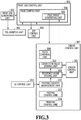
- FIG. 3 is a block diagram showing an example of the software configuration of the printing apparatus 10 according to the present embodiment.
- the printing request from the host PC 20 is input to a print job generating unit 301 within the printing apparatus 10.
- PDL data data in which a print target image is described in PDL (Page Description Language)
- printing setting information specifying conditions at the time of printing (sheet size, sheet type, number of pages, number of printing copies and the like) is included.
- the print job generating unit 301 generates a job (print job) for performing printing processing in the print engine 200 based on the input printing request.
- the generated print job is registered in a print job control unit 303.
- the print job control unit 303 instructs a page control unit 304 to start processing in order from the first page for all the printing-target pages included in the registered print job and causes the page control unit 304 to start printing processing (page processing) of each page.
- the page control unit 304 Upon receipt of the instructions to start processing from the print job control unit 303, the page control unit 304 performs and controls the page processing of the specified page. Then, in a case of receiving a notification to the effect that it is possible to start processing of the next page from the page control unit 304, the print job control unit 303 instructs the page control unit 304 to start processing of the next page. This is performed for all the pages. Then, in a case of receiving a notification of completion of the page processing of all the pages from the page control unit 304, the print job control unit 303 notifies the print job generating unit 301 of completion of the print job.
- a PDL analysis unit 302 analyzes the PDL data included in the printing request received from the host PC20 and converts the PDL data into intermediate data. Then, a RIP control unit 305 rasterizes the intermediate data and converts into image data in the bitmap format for each page.
- a page image generating unit 306 generates print image data of each page by performing tone correction processing for the image data of each page in the bitmap format generated in the RIP control unit 305.
- tone correction data (in the following, described as "correction value") corresponding to the sheet type of the sheet that is used for printing of the page is reflected each time.
- the print image of each page is called "page image”.
- the page image data generated in the page image generating unit 306 is sent to an engine control unit 307.
- the engine control unit 307 includes a patch combining unit 308, a reference value storing unit 309, a correction value storing unit 310, a sensor control unit 311, a feeding cassette management unit 312, a feeding control unit 313, and a printing control unit 314.
- the patch combining unit 308 combines a patch whose tone is made different stepwise for each color of the color materials (recording materials) for the page image received from the page image generating unit 306.
- the data of the page image in the following, called "patch-attached page image" to which the patch of each color (here, each color of CMYK) is added by the combining processing is sent to the printing control unit 314.
- the feeding control unit 313 conveys and supplies the sheet accommodated in the feeding cassette 223 by controlling the feeding cassette 223 in accordance with the sheet size and sheet type designated by the print job.
- the printing control unit 314 prints an image on the sheet supplied from the feeding control unit 313 by using the patch-attached page image data and discharges the sheet.
- the sensor control unit 311 acquires color measurement data by performing density measurement of the patch formed on the printed sheet by controlling the color measurement sensor 200.
- the reference value storing unit 309 stores the density reference value (in the following, simply described as "reference value”) for tone correction, which is generated based on the color measurement data acquired by the sensor control unit 311, for each kind of sheet (sheet type) accommodated in the feeding cassette 223.
- the correction value storing unit 310 stores the density correction value (in the following, simply described as "correction value”) for tone correction, which is obtained by the comparing the reference value stored by the reference value storing unit 309 and the color measurement data acquired by the sensor control unit 311, for each type of the sheet accommodated in the feeding cassette 223.
- the feeding cassette management unit 312 manages information relating to the sheets accommodated in all the feeding cassettes 223 comprised by the printing apparatus 10. Further, the feeding cassette management unit 312 also performs reset control of the reference value stored by the reference value storing unit 309 and the correction value stored by the correction value storing unit 310. In the present embodiment, it is assumed that the information relating to the sheet is managed in a table method and the management table for the above-described reference value and the management table for the above-described correction value are provided, respectively. Details of the management table and details of the reset processing of the reference value and the correction value will be described later.
- a UI control unit 315 displays a predetermined UI screen on the operation unit 110, makes a request to register the sheet type to the feeding cassette management unit 312, and so on.
- FIGS. 4A to 4D are sequence diagrams showing a flow of the processing in the printing apparatus 10.
- the series of operation shown in the sequence diagrams in FIGS. 4A to 4D is implemented by the CPU 101 reading a program stored in the ROM 102 onto the RAM 103 and executing the program.
- Symbol "S" in the explanation of the following sequence diagrams and flowcharts represents a step.
- the print job generating unit 301 generates a print job based on the printing request from the host PC 20 and registers the print job in the print job control unit 303 (S401).
- the print job control unit 303 determines the execution order of the registered print jobs and starts processing in accordance with the determined order (S402).
- S403 to S429 that follow are repeated the number of times corresponding to the number of pages designated by the processing-target pint job.
- the print job control unit 303 instructs the page control unit 304 to start processing of a target page (Nth page) in the target print job (S403).
- the page control unit 304 makes an inquiry about from which feeding cassette the sheet of the sheet size and sheet type designated for the Nth page is fed to the feeding cassette management unit 312 (S404).
- the feeding cassette management unit 312 determines from which feeding cassette to feed the sheet from the information on the sheet size and the sheet type designated for the Nth page and returns the results to the page control unit 304 (S405).
- the page control unit 304 having received the information on the feeding cassette that is used from the feeding cassette management unit 312 instructs the feeding control unit 313 to feed the sheet from the feeding cassette that is identified by the information (S406).
- the feeding control unit 313 feeds the sheet from the feeding cassette determined by the feeding cassette management unit 312 in accordance with the feeding instructions from the page control unit 304 (S407) and returns the feeding results to the page control unit 304 (S408).
- the page control unit 304 In a case where the feeding results from the feeding control unit 313 indicate "normal", the page control unit 304 notifies the print job control unit 303 that it is made possible to start the processing of the next page (S409), Further, upon receipt of the feeding results of "normal", the page control unit 304 instructs the page image generating unit 306 to generate and transfer a page image (S410). At this time, page image generating unit 306 is also notified of the information on the feeding cassette from which the sheet has been fed, the sheet size, and the sheet type.
- the page image generating unit 306 Upon receipt of the instructions to generate and transfer a page image, the page image generating unit 306 makes a request for the correction value corresponding to the sheet type relating to the feeding to the correction value storing unit 310 based on the notified information (S411).
- the correction value storing unit 310 searches whether the correction value corresponding to the sheet type relating to the feeding is stored in the RAM 103 (S412). In a case where the correction value in question is found as a result of the search, the correction value storing unit 310 notifies the page image generating unit 306 of the found correction value (S413). In this case, the page image generating unit 306 generates a page image by performing the tone correction processing using the notified correction value (S414).
- the correction value storing unit 310 notifies the page image generating unit 306 that the correction value in question does not exist (S415).
- the page image generating unit 306 generates a page image without performing the tone correction processing (S416).
- the page image generating unit 306 transfers the generated page image data of the Nth page to the patch combining unit 308 along with the information (in the following, called "feeding information") relating to the sheet fed at S407.
- the feeding information information on the sheet size and sheet type of the sheet, the feeding cassette accommodating the sheet, and the like is included.
- the patch combining unit 308 generates a patch-attached page image in the margin of the page image received from the page image generating unit 306 by combining the above-described patch of each color (S418). Next, the patch combining unit 308 transmits the generated patch-attached page image data to the printing control unit 314 along with the above-described feeding information and gives instructions to perform printing (S419). Upon receipt of the instructions to perform printing, the printing control unit 314 performs printing on the sheet supplied from the feeding control unit 313 in accordance with the received patch-attached page image data (S420).
- the printing control unit 314 notifies the page control unit 304 and the sensor control unit 311 of completion of printing (completion of discharge) (S421).
- the above-described feeding information is attached.
- the page control unit 304 having received the notification of completion of printing (completion of discharge) notifies the print job control unit 303 of completion of the processing of the Nth page (S422).
- the sensor control unit 311 similarly having received the notification of completion of printing (completion of discharge) measures the density of the patch formed on the sheet by the printing at S420 by using the color measurement sensor 220 (S423).
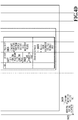
- FIG. 5 is a diagram schematically showing the way the color of the patch is measured.
- tone pattern images consist of a plurality of color patches for each of CMYK for real-time tone correction are printed in the margin area inside the sheet 222 and outside a printing-guaranteed area 600 in the direction parallel to the conveyance direction so that their positions are aligned with the positions of the two color measurement sensors 220a and 220b.
- the printing-guaranteed area 600 is the portion that will be the final product and the area that guarantees the print quality of the target image designated by a print job.
- the portion outside the printing-guaranteed area 600 is the area in part of which it is possible to form an image but which is premised not to be used as the final product but cut off or removed.
- each of patches 610, 620, 630, and 640 for each of CMYK includes 10 sub patches whose density is varied at intervals of 10%.
- the density of the leftmost sub patch is 100% and the density decreases at intervals of 10% in the rightward direction and the density of the rightmost sub patch is 10%.
- each patch of magenta, yellow, and black also has the patch configuration in which ten sub patches form one set and the patch density of each color is read by the color measurement sensors 220a and 220b.
- the sensor control unit 311 notifies the reference value storing unit 309 of the color measurement results of each color of CMYK thus obtained in association with the above-described feeding information (S424).
- FIG. 6A shows an example of the measured value data (density value data) obtained by expressing the patch density in numbers at 1,024 levels. As described previously, on the sheet 222, the four kinds of patch of each of CMYK are printed and each patch includes ten sub patches, and therefore, as shown in FIG. 6A , a total of 40 measured values are obtained. It is assumed that a value obtained by applying an offset to the value read by the color measurement sensor 220 in view of the characteristic of the color measurement sensor 220 and the white reference value or the like of the sheet is also handled here as the measured value (density value).
- the reference value storing unit 309 having received the notification of the color measurement results searches whether the reference value corresponding to the sheet type specified by the feeding information attached to the notification is stored (S425). In a case where the reference value is found, the reference value storing unit 309 calculates a correction value based on the found reference value and the notified color measurement results as described above (S426). Then, the reference value storing unit 309 notifies the correction value storing unit 310 of the calculated correction value (S427).
- the correction value storing unit 310 having received the notification stores the correction value relating to the notification in the RAM 103 in association with the sheet type specified by the sheet information (S428).
- the reference value storing unit 309 stores the color measurement results notified by the sensor control unit 311 in the RAM 103 as a new reference value in association with the sheet type specified by the feeding information (S429). That is, the density value obtained by measuring the patch formed on a sheet relating to the first feeding after a new sheet is accommodated in a case where exchange of sheets or the like is performed for a certain feeing cassette is stored as a new reference value in association with the sheet type thereof.
- the reference value storing unit 309 stores the measured value obtained by the color measurement as a new "reference value" in association with the sheet type thereof.
- the correction value is calculated from the measurement results. Specifically, a difference between the reference value associated with the already-registered sheet type and the measured value relating to the notification is found and the difference is taken as the correction value.
- FIG. 6B and FIG. 6C respectively show an example of reference value data and an example of correction value data, both stored in a table format in the reference value storing unit 309 and the correction value storing unit 310, respectively.
- an ID for identification (here, "TBL_S01", “TBL_C01”) is attached so that it is made possible to refer to them in a management table, to be described later.
- the value derived based on the measured value of the preceding page and the reference value is stored as the correction value for the next page, but this is not limited.
- the correction value is obtained by storing in advance the measured value for derivation of the correction value of the next page and finding a difference between the stored measured value of the preceding page and the reference value each time in the processing of the next page.
- each piece of processing at S403 to S429 is described in a loop in FIGS. 4A to 4D and this means that each piece of processing at S403 to S429 is performed for all the pages of the print job registered in the print job control unit 303. Further, it is made possible to issue instructions to start processing for the Nth page shown at S403 in a case where a next page processing start possible notification at S409 is received.
- the print job control unit 303 determines whether the Nth page is the last page of the target print job (S430). In a case where the determination results indicate that the Nth page is the last page, the print job control unit 303 notifies the print job generating unit 301 of completion of the target print job (S431).
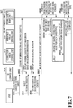
- FIG. 7 is a sequence diagram showing a flow of processing at the time of sheet exchange.
- Each operation in the printing apparatus 10 among the series of operation shown in the sequence diagram in FIG. 7 is implemented by the CPU 101 reading a program stored in the ROM 102 onto the RAM 103 and executing the program.
- the characteristic is different for different sheet types, and therefore, it is necessary to store the above-described reference value for each sheet type in order for the printing apparatus 10 to perform tone correction correctly.
- the printing apparatus is designed so as to be capable of adapting to many sheet types, but the sheet that is used actually at the time of printing is the sheet accommodated in the feeing cassette.
- the reference value storing unit 309 of the present embodiment stores only the reference value corresponding to the sheet type of the sheet actually accommodated in the feeding cassette 223. Consequently, in a case where the sheet type of the sheet that is accommodated in the feeding cassette 223 is changed, the reference value is reset.
- the reference value corresponding to the sheet type (for example, plain paper) of the sheet that is removed is cleared and the reference value corresponding to the sheet type (for example, coated paper) of the sheet that is set newly is set.
- the specific operation is explained.
- a user operates a main screen (not shown schematically) of the operation unit 110 of the printing apparatus 10 and selects a feeding cassette setting screen, which is a UI screen for setting a sheet to the feeding cassette (S801).
- the UI control unit 315 acquires information (information on sheet size and sheet type of each feeding cassette) relating to the sheets that are set to all the feeding cassettes comprised by the printing apparatus 10 from the feeding cassette management unit 312 (S802).
- the UI control unit 315 displays the feeding cassette setting screen on the operation unit 110 by using the information acquired at S802 (S803).
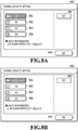
- FIG. 8A shows an example of the feeding cassette setting screen.
- FIG. 8A shows the state where the button 901 corresponding to [feeding cassette 1] is selected and as information indicating the sheet size and the sheet type registered for the [feeding cassette 1] being selected, [A4 plain paper 3] is displayed.
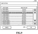
- the UI control unit 315 switches the UI display on the operation unit 110 from the Feeding cassette setting screen 900 to a Sheet setting screen 1000 as shown in FIG. 9 (S805).
- the user sets a desired sheet (here, sheet whose sheet type is [plain paper 1]) in the feeding cassette selected at S804 and selects the sheet type of the sheet that is newly set on the Sheet setting screen 1000 displayed on the operation unit 110 (S806).
- FIG 9 shows the state where [plain paper 1] is selected.
- the UI control unit 315 updates the display contents as well as returning the UI display on the operation unit 110 from the Sheet setting screen 1000 to the Feeding cassette screen 900.
- FIG. 8B shows the state of the updated Feeding cassette screen 900. As information indicating the sheet size and the sheet type newly selected for [feeding cassette 1], [A4 plain paper 1] is displayed.
- the UI control unit 315 requests the feeding cassette management unit 312 to register the feeding cassette selected by the user at S804 and the sheet type selected by the user at S806 (S807).
- the feeding cassette management unit 312 checks whether or not the sheet type relating to the registration request is, 1) different from the sheet type of the sheet removed from the target feeding cassette, and 2) registered as the sheet type that is used in another feeding cassette other than the target feeding cassette (S808). Then in a case where the sheet type relating to the registration request is different from the sheet type of the removed sheet and is the sheet type not registered for another feeding cassette, the feeding cassette management unit 312 clears the reference value corresponding to the sheet type of the removed sheet (S809). Further, the feeding cassette management unit 312 checks whether the correction value corresponding to the sheet type of the removed sheet is stored in the correction value storing unit 310 and clears the correction value in a case where the correction value is stored (S810).
- the feeding cassette management unit 312 performs registration processing of the sheet type of the sheet newly set by the user (S811). In a case where the registration is completed, the feeding cassette management unit 312 notifies the UI control unit 315 of registration completion (S812).
- a first case is a case where the reference value and the correction value are managed collectively for each sheet type.
- a second case is a case where the reference value and the correction value are managed individually for each feeding cassette.
- a request to register sheet information on the feeding cassette relating to user selection is received from the UI control unit 315.
- This registration request includes information (cassette ID and the like) capable of specifying the selected feeding cassette and information indicating the sheet size and the sheet type of the sheet that is set in the selected feeding cassette by a user.
- information cassette ID and the like
- a user does not perform the setting or the like of the sheet type by opening the Feeding cassette setting screen 900.
- a reregistration request for the same sheet type is issued.
- the reference value storing unit 309 and the correction value storing unit 310 are each instructed to delete the reference value and the correction value corresponding to the sheet type before being changed.
- the reference value storing unit 309 and the correction value storing unit 310 delete the data of the reference value and the correction value (see FIG. 6B and FIG. 6C described previously) stored in association with the sheet type before being changed, respectively.
- the processing advances to S1105.
- FIG. 12A shows the state of the management table for the reference value (in the following, described as "reference value management table") before the target record is deleted and
- FIG. 12B shows the state after the target record is deleted.
- the record of [CST1] indicates that printing is performed on the sheets of [30000] pages (on the sheet of [30000th] page) of [plain paper 3], which is the accumulated number from the time at which the electric power source was turned on at [2019/07/18 10 : 04 : 06], and the measured value obtained by performing color measurement for the printing results is registered as the reference value.
- FIG. 13A shows the state of the management table for the correction value (in the following, described as "correction value management table") before the target record is deleted and
- FIG. 13B shows the state after the target record is deleted.
- the color measurement is performed for the output results of the print job whose processing has been resumed after the sheet exchange and based on the obtained measured value, a new record including information on the changed sheet type for the selected feeding cassette is added to the reference value management table and the correction value management table.
- the reference value data corresponding to the changed sheet type relating to the registration request is generated and registered newly in the reference value storing unit 309 based on the printing results of the printed page immediately after the resumption and link processing is performed so that the reference value data is referred to.
- FIG. 12C and FIG. 13C show the reference value management table and the correction value management table, respectively, in the state where a new record is added in a case where the sheet type of [CST1] is changed from [plain paper 3] to [plain paper 1].
- a record including information on the selected feeding cassette and the changed sheet type is added to the reference value management table.
- the record that is added at this time is a record for which link processing has been performed so that the already-registered reference value data and correction value data corresponding to the same sheet type as the changed sheet type are referred to. In a case where the registration processing at S1108 or S1109 is completed, this processing is terminated.
- a request to register sheet information on the selected feeding cassette is received from the UI control unit 315.
- whether or not the contents of the registration request received at S1201 entail the change of the sheet type is determined. In a case where the change of the sheet type is not entailed, this processing is terminated. On the other hand, in a case where the change of the sheet type is entailed, the processing advances to S1203.
- the correction value for tone correction is fed back continuously without a break between a plurality of print jobs.
- the correction value for tone correction is fed back continuously without a break between a plurality of print jobs.
- Embodiments) of the present invention can also be realized by a computer of a system or apparatus that reads out and executes computer executable instructions (e.g., one or more programs) recorded on a storage medium (which may also be referred to more fully as a 'non-transitory computer-readable storage medium') to perform the functions of one or more of the above-described embodiment(s) and/or that includes one or more circuits (e.g., application specific integrated circuit (ASIC)) for performing the functions of one or more of the above-described embodiment(s), and by a method performed by the computer of the system or apparatus by, for example, reading out and executing the computer executable instructions from the storage medium to perform the functions of one or more of the above-described embodiments) and/or controlling the one or more circuits to perform the functions of one or more of the above-described embodiment(s).
- computer executable instructions e.g., one or more programs
- a storage medium which may also be referred to more fully as a '
- the computer may comprise one or more processors (e.g., central processing unit (CPU), micro processing unit (MPU)) and may include a network of separate computers or separate processors to read out and execute the computer executable instructions.
- the computer executable instructions may be provided to the computer, for example, from a network or the storage medium.
- the storage medium may include, for example, one or more of a hard disk, a random-access memory (RAM), a read only memory (ROM), a storage of distributed computing systems, an optical disk (such as a compact disc (CD), digital versatile disc (DVD), or Blu-ray Disc (BD)TM), a flash memory device, a memory card, and the like.
Landscapes
- Engineering & Computer Science (AREA)
- Theoretical Computer Science (AREA)
- General Engineering & Computer Science (AREA)
- Physics & Mathematics (AREA)
- General Physics & Mathematics (AREA)
- Human Computer Interaction (AREA)
- Computational Linguistics (AREA)
- Quality & Reliability (AREA)
- Microelectronics & Electronic Packaging (AREA)
- Control Or Security For Electrophotography (AREA)
- Accessory Devices And Overall Control Thereof (AREA)
- Color Electrophotography (AREA)
Applications Claiming Priority (1)
| Application Number | Priority Date | Filing Date | Title |
|---|---|---|---|
| JP2020031678A JP7766997B2 (ja) | 2020-02-27 | 2020-02-27 | 印刷装置、印刷制御方法及びプログラム |
Publications (1)
| Publication Number | Publication Date |
|---|---|
| EP3872616A1 true EP3872616A1 (en) | 2021-09-01 |
Family
ID=74758581
Family Applications (1)
| Application Number | Title | Priority Date | Filing Date |
|---|---|---|---|
| EP21159173.0A Pending EP3872616A1 (en) | 2020-02-27 | 2021-02-25 | Printing apparatus, printing control method, and storage medium |
Country Status (5)
| Country | Link |
|---|---|
| US (2) | US11562189B2 (enExample) |
| EP (1) | EP3872616A1 (enExample) |
| JP (1) | JP7766997B2 (enExample) |
| KR (1) | KR102746718B1 (enExample) |
| CN (1) | CN113306302B (enExample) |
Families Citing this family (1)
| Publication number | Priority date | Publication date | Assignee | Title |
|---|---|---|---|---|
| JP7766997B2 (ja) * | 2020-02-27 | 2025-11-11 | キヤノン株式会社 | 印刷装置、印刷制御方法及びプログラム |
Citations (3)
| Publication number | Priority date | Publication date | Assignee | Title |
|---|---|---|---|---|
| US20050169651A1 (en) * | 2004-01-30 | 2005-08-04 | Brother Kogyo Kabushiki Kaisha | Image-forming device |
| JP2007036411A (ja) * | 2005-07-25 | 2007-02-08 | Konica Minolta Business Technologies Inc | 画像処理装置および画像処理方法 |
| JP2015225170A (ja) | 2014-05-27 | 2015-12-14 | コニカミノルタ株式会社 | 画像形成システム、画像形成方法および中継装置 |
Family Cites Families (9)
| Publication number | Priority date | Publication date | Assignee | Title |
|---|---|---|---|---|
| JP2007266747A (ja) * | 2006-03-27 | 2007-10-11 | Toshiba Corp | 画像形成装置及びこの装置のキャリブレーション方法 |
| JP4895357B2 (ja) * | 2006-03-31 | 2012-03-14 | キヤノン株式会社 | 画像形成装置、画像形成方法 |
| JP5484085B2 (ja) | 2010-01-18 | 2014-05-07 | キヤノン株式会社 | 画像形成装置及びその画質補正方法 |
| JP2014219525A (ja) * | 2013-05-08 | 2014-11-20 | シャープ株式会社 | 画像形成装置 |
| JP6115546B2 (ja) * | 2014-11-12 | 2017-04-19 | コニカミノルタ株式会社 | 情報処理装置、情報処理装置の制御方法、および画像形成システム |
| JP6511835B2 (ja) * | 2015-01-30 | 2019-05-15 | コニカミノルタ株式会社 | 画像形成装置及び画像形成システム並びに画像形成制御方法 |
| JP2017042929A (ja) * | 2015-08-24 | 2017-03-02 | 富士ゼロックス株式会社 | 画像形成装置及び画像形成プログラム |
| JP2018005173A (ja) * | 2016-07-08 | 2018-01-11 | コニカミノルタ株式会社 | 画像形成装置及びプログラム |
| JP7766997B2 (ja) * | 2020-02-27 | 2025-11-11 | キヤノン株式会社 | 印刷装置、印刷制御方法及びプログラム |
-
2020
- 2020-02-27 JP JP2020031678A patent/JP7766997B2/ja active Active
-
2021
- 2021-02-19 US US17/179,464 patent/US11562189B2/en active Active
- 2021-02-25 EP EP21159173.0A patent/EP3872616A1/en active Pending
- 2021-02-26 KR KR1020210026285A patent/KR102746718B1/ko active Active
- 2021-03-01 CN CN202110227327.2A patent/CN113306302B/zh active Active
-
2022
- 2022-12-20 US US18/084,780 patent/US11829823B2/en active Active
Patent Citations (3)
| Publication number | Priority date | Publication date | Assignee | Title |
|---|---|---|---|---|
| US20050169651A1 (en) * | 2004-01-30 | 2005-08-04 | Brother Kogyo Kabushiki Kaisha | Image-forming device |
| JP2007036411A (ja) * | 2005-07-25 | 2007-02-08 | Konica Minolta Business Technologies Inc | 画像処理装置および画像処理方法 |
| JP2015225170A (ja) | 2014-05-27 | 2015-12-14 | コニカミノルタ株式会社 | 画像形成システム、画像形成方法および中継装置 |
Also Published As
| Publication number | Publication date |
|---|---|
| US20210271942A1 (en) | 2021-09-02 |
| US11829823B2 (en) | 2023-11-28 |
| US11562189B2 (en) | 2023-01-24 |
| JP2021135393A (ja) | 2021-09-13 |
| KR20210109472A (ko) | 2021-09-06 |
| US20230122307A1 (en) | 2023-04-20 |
| CN113306302A (zh) | 2021-08-27 |
| CN113306302B (zh) | 2023-06-16 |
| KR102746718B1 (ko) | 2024-12-27 |
| JP7766997B2 (ja) | 2025-11-11 |
Similar Documents
| Publication | Publication Date | Title |
|---|---|---|
| JP2010263368A (ja) | 色変換設定プログラム、色変換設定方法、色変換処理プログラム、色変換処理装置 | |
| US11503183B2 (en) | Image formation apparatus and storing medium | |
| US11812004B2 (en) | Printing apparatus, method of controlling the same, and storage medium | |
| US11356581B2 (en) | Apparatus and image forming method for performing gradation correction on an image using generated gradation correction data | |
| US11695893B2 (en) | Image forming apparatus and method of controlling image forming apparatus | |
| US11303781B2 (en) | Apparatus and method | |
| US11829823B2 (en) | Printing apparatus, printing control method, and storage medium | |
| JP6258670B2 (ja) | 画像形成装置及び画像形成システム | |
| US11516358B2 (en) | Image forming apparatus, method of controlling the same, and medium | |
| US11789394B2 (en) | Print system, printing apparatus, information processing apparatus, method of controlling the same, and storage medium | |
| JP6350100B2 (ja) | プリンタコントローラ及びジョブ処理制御プログラム並びにジョブ処理制御方法 | |
| JP2021153242A (ja) | 情報処理装置、情報処理方法、印刷システムおよびプログラム | |
| JP6922607B2 (ja) | 画像形成装置、ジョブ処理方法及びジョブ処理制御プログラム | |
| US20240305735A1 (en) | Image forming apparatus, control method for image forming apparatus, and storage medium that are capable of acquiring adjustment image that can be sufficiently used for position adjustment of image regardless of size of sheet when position adjustment of image with respect to sheet is performed | |
| US20250021043A1 (en) | Image forming apparatus, method of controlling the same, and storage medium | |
| CN110471266B (zh) | 图像形成装置 | |
| JP6586869B2 (ja) | 画像形成装置及びプログラム | |
| JP2023104101A (ja) | 画像形成装置 | |
| CN112578649A (zh) | 图像形成装置 | |
| JP2022013703A (ja) | 画像形成装置 | |
| JP2023084509A (ja) | 画像形成装置 | |
| RU2574853C2 (ru) | Устройство задания настроек, система контроля, способ задания настроек обработки контроля и программа | |
| JP2022026939A (ja) | 画像形成装置 |
Legal Events
| Date | Code | Title | Description |
|---|---|---|---|
| PUAI | Public reference made under article 153(3) epc to a published international application that has entered the european phase |
Free format text: ORIGINAL CODE: 0009012 |
|
| STAA | Information on the status of an ep patent application or granted ep patent |
Free format text: STATUS: THE APPLICATION HAS BEEN PUBLISHED |
|
| AK | Designated contracting states |
Kind code of ref document: A1 Designated state(s): AL AT BE BG CH CY CZ DE DK EE ES FI FR GB GR HR HU IE IS IT LI LT LU LV MC MK MT NL NO PL PT RO RS SE SI SK SM TR |
|
| STAA | Information on the status of an ep patent application or granted ep patent |
Free format text: STATUS: REQUEST FOR EXAMINATION WAS MADE |
|
| 17P | Request for examination filed |
Effective date: 20220301 |
|
| RBV | Designated contracting states (corrected) |
Designated state(s): AL AT BE BG CH CY CZ DE DK EE ES FI FR GB GR HR HU IE IS IT LI LT LU LV MC MK MT NL NO PL PT RO RS SE SI SK SM TR |
|
| STAA | Information on the status of an ep patent application or granted ep patent |
Free format text: STATUS: EXAMINATION IS IN PROGRESS |
|
| 17Q | First examination report despatched |
Effective date: 20240426 |
|
| GRAP | Despatch of communication of intention to grant a patent |
Free format text: ORIGINAL CODE: EPIDOSNIGR1 |
|
| STAA | Information on the status of an ep patent application or granted ep patent |
Free format text: STATUS: GRANT OF PATENT IS INTENDED |
|
| INTG | Intention to grant announced |
Effective date: 20250916 |