EP3872581A1 - Vorrichtung zur sicheren ansteuerung und system - Google Patents
Vorrichtung zur sicheren ansteuerung und system Download PDFInfo
- Publication number
- EP3872581A1 EP3872581A1 EP21155886.1A EP21155886A EP3872581A1 EP 3872581 A1 EP3872581 A1 EP 3872581A1 EP 21155886 A EP21155886 A EP 21155886A EP 3872581 A1 EP3872581 A1 EP 3872581A1
- Authority
- EP
- European Patent Office
- Prior art keywords
- output
- designed
- counting
- processing unit
- activation element
- Prior art date
- Legal status (The legal status is an assumption and is not a legal conclusion. Google has not performed a legal analysis and makes no representation as to the accuracy of the status listed.)
- Granted
Links
Images

Classifications
-
- G—PHYSICS
- G05—CONTROLLING; REGULATING
- G05B—CONTROL OR REGULATING SYSTEMS IN GENERAL; FUNCTIONAL ELEMENTS OF SUCH SYSTEMS; MONITORING OR TESTING ARRANGEMENTS FOR SUCH SYSTEMS OR ELEMENTS
- G05B19/00—Program-control systems
- G05B19/02—Program-control systems electric
- G05B19/04—Program control other than numerical control, i.e. in sequence controllers or logic controllers
- G05B19/042—Program control other than numerical control, i.e. in sequence controllers or logic controllers using digital processors
- G05B19/0428—Safety, monitoring
Definitions
- the present invention relates to a device for the safe implementation of a control and a system for the safe control of a medical device.
- the control part records its tasks relevant to the control and interacts with the safety part across the isolation barrier by exchanging information and parameters.
- the safety part continuously interprets the information and, in the event of a problem, puts the device in a safe state.
- display systems Supervisory Control and Data Acquisition, SCADA
- SCADA Supervisory Control and Data Acquisition
- this security is provided via the bus card that is independent of the mainboard and operating system.
- Data points on the CAN bus are checked for up-to-dateness and, if necessary, signaled locally (beeper). For most of these systems it is sufficient to ensure that a corresponding reliable signaling and / or a shutdown of energy for movement actuators or the like is given in order to achieve a safe state.
- the object is achieved by a device for the safe implementation of a control, the device with a processor-controlled processing unit which is designed to run a program, a counting element which is electrically coupled to the processing unit and is designed for a number of To count counting signals that are output by the processing unit and to output this number as a count value, a comparison element which is electrically coupled to the processing unit and the counting element and is designed to compare the count value with a target value which is output by the processing unit , and output an equality signal in the event of a match, and an activation element which is designed to output a holding voltage as long as the activation element receives the equality signal and repeatedly receives a trigger signal from the processing unit, the holding voltage tion causes an active state of the control, the program having a plurality of first instructions, which are each designed to output one or more of the counting signals to the counting element, has a second instruction which is designed to output the setpoint, the one corresponds to the expected sum of the pulses output by the first instructions, and has a third instruction
- a special feature of the present invention is the connection of different elements based on different functional principles. On the one hand, there is a differentiation between software and hardware. In addition, however, various hardware elements are used that differ with regard to one or more of the following characteristics: Electronic complexity, required amount of energy to bring about a change of state and an undesirable amount of energy input that leads to a malfunction or malfunction.
- the processor-controlled processing unit is one of the type of hardware that can be viewed as electronically very complex, such as a microcontroller or microprocessor, in which a state change can be brought about with a very small amount of energy, in particular flipping a bit, and in the case of a small, externally introduced amount of energy can lead to a malfunction.
- a microcontroller or microprocessor in which a state change can be brought about with a very small amount of energy, in particular flipping a bit, and in the case of a small, externally introduced amount of energy can lead to a malfunction.
- the counting element is less complex than the processor-controlled processing unit and requires a larger amount of energy to bring about a change of state, e.g. a 5V edge or a 5V pulse to increase the count value. In order to cause a malfunction of the counting element, a greater amount of energy is required than in the case of the processor-controlled processing unit.
- the comparison element and the activation element are structured even more simply.
- the activation element can be constructed very simply and require a considerable input of energy in order to be transferred from an inactive state to the active state. This also means that a very considerable amount of undesired energy is required for a disruption.
- the processor-controlled processing unit verifies the tasks registered with it.
- the processing unit is in turn secured by downstream components and thus achieves a high level of security.
- the program has first, second and third instructions to ensure safe control.
- Each of the first instructions causes one or more counting signals to be output to the counting element.
- each first instruction sends exactly one counting signal.
- each first instruction can also send several counting signals and several first instructions can send a different number of counting signals.
- the counting element counts the number of counting signals.
- the first instructions are implemented at points in the program that must be run through for correct processing. It is up to the person skilled in the art how narrow or how wide the coverage should be with the first instructions.
- the second instruction is implemented at a further point within the program, which corresponds to the expected sum of the pulses output by the first instructions, which must have been passed through when the second instruction is reached in order to function correctly. This setpoint is output to the comparison element.
- the third instruction Before the third instruction is carried out, further checks are carried out, for example whether any further prerequisites for carrying out the control are met. In particular, it can be checked whether a process that is to be operated by executing the program is authorized to carry out the control. Additionally or alternatively, it can be checked whether any framework conditions that are determined by a second process should prevent the control from being carried out. If the check is successful, the third instruction, which sends the trigger signal, is executed.
- the comparison element expects that the counter value transmitted by the counter element corresponds to the nominal value output by means of the second instruction.
- the equality signal is only output if this is the case. If the program has not run through all of the first instructions as expected, the count value does not match the setpoint and the equality signal is not output. Activation cannot be carried out.
- the activation element expects the equality signal from the comparison element.
- the trigger signal is also required to output the holding voltage. Activation is thus prevented if the equality signal and / or the trigger signal are missing. Specifically, if the third instruction is not executed, the trigger signal is missing. If an error occurred when checking the execution of the first instructions, the equality signal is missing. It is not possible to carry out the activation in these two cases.
- the special design of the activation element also means that even after the initial presence of the equality signal and the trigger signal, these signals must continue to be available, repeated for the trigger signal, in order to bring about an active state of the control by means of the holding voltage. If the equality signal fails or the trigger signal fails for a certain period of time, the holding voltage drops out and the activation process is stopped. This ensures that the first, second and third instructions are processed correctly.
- the activation element has a capacitor which is discharged in the activation element over time, the activation element not outputting the holding voltage when a state of charge of the capacitor falls below a threshold value.
- a simple and very reliable physical principle ensures that the activation element becomes inactive, i.e. no longer outputs the holding voltage and thus prevents or terminates the activation.
- a very considerable unexpected disturbance energy would be required, which can practically be ruled out. This ensures that the activation element becomes inactive if the equality signal is missing and / or the trigger signal does not arrive repeatedly.
- the device has a relay which is electrically coupled to the activation element and is designed to switch through a current path when the holding voltage is applied and to interrupt the current path when the holding voltage is not applied.
- the relay is a very simple mechanical component with electrical control. A large amount of voltage is required to cause a change in state, and a large amount of disturbance energy is also required to cause a malfunction.
- the activation element is a monoflop with a first input, a second input and an output, the first input receiving the equality signal, the second input receiving the trigger signal and the output outputting the holding voltage.
- This configuration enables a simple and reliable implementation of the activation element.
- the counting element, the comparison element and the activation element are each designed as separate components.
- This configuration makes it possible to keep the individual components simple and thereby achieve a high level of reliability for the individual components.
- the counting element, the comparison element and the activation element are each formed in a separate housing.
- This configuration makes it possible to keep the individual components simple and thereby achieve a high level of reliability for the individual components. Furthermore, the spatial separation can reduce or prevent undesirable interaction between individual components, in particular if the housing has a shielding property, that is to say, for example, is made of metal.
- the counting element is designed as a counter and / or the comparison element is designed as a comparator and / or the activation element is designed as a monoflop.
- This configuration makes it possible to use standard components that are particularly robust and enable error-free operation. This ensures that the control is carried out reliably in the long term.
- the object is achieved by a system for the safe control of a medical device, comprising the medical device and a device described above, the medical device being controlled by the device and a function of the medical device being dependent on correct execution of the program and depends on the presence of the holding voltage.
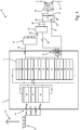
- Fig. 1 shows an embodiment of a device 10 for the reliable implementation of a triggering.
- the device 10 has a process-controlled processing unit 12 which is designed to process a program 14.
- the device 10 also has a counting element 16 which is electrically coupled to the processing unit 12 and is designed to count a number of counting signals 18 that are output by the processing unit 12, here via a port IO5, and this number as Output count value 20.
- the device 10 also has a comparison element 22 which is electrically coupled to the processing unit 12 and to the counting element 16.
- the comparison element 22 is designed to compare the count value 20 with a setpoint value 24 which is output by the processing unit 12, here via the ports IO6, IO7, IO8, IO9, and to output an equality signal 26 if they match.
- an activation element 28 which is designed to output a holding voltage 30 as long as the activation element 28 receives the equality signal 26 and repeatedly a trigger signal 32 from the processing unit 12 via the port IO10, the holding voltage 30 having an active state the control causes.
- the device 10 finally also has a relay 34 which is electrically coupled to the activation element 28.
- the relay 34 is designed to switch through a current path 36 when the holding voltage 30 is applied, and to interrupt the current path 36 when the holding voltage is not applied.
- the program 14 has a plurality of first instructions 38, each of which is designed to output one or more counting signals 18 to the counting element 16, symbolically represented here by means of the lines.
- the program 14 also has a second instruction 40 which is designed to output the setpoint value 24, which corresponds to an expected sum of the pulses output by the first instructions 38.
- the program 14 also has a third instruction which is designed to output the trigger signal 32.
- the activation element 28 has, symbolically shown here, a capacitor 44 which is discharged in the activation element 28 over time, the activation element 28 not outputting the holding voltage 30 when a state of charge of the capacitor 44 falls below a threshold value.
- the program 14 has a communication routine 46 which forms a connection to a bus 50 via an interface 48 with the ports IO1, IO2, IO3, IO4, here via an optocoupler 52.
- the communication routine sends 46 a basic key of the device 10, for example a unique identification number, via the interface 48 and the bus 50 to a main controller (not shown).
- a process key already received earlier is moved from a first memory location to a second memory location.
- the communication routine 46 receives a new process key from the main controller via the bus 50 and the interface 48. After step 58 has been successfully completed, a new process key is then located in the first memory location and a process key that has already been received is in the second memory location.
- One of these process keys or both process keys can be used, for example, to check before or during the execution of the third instruction 42, whether the request for control to the device 12 was requested by an authorized controller or by an authorized person.
- the communication routine 46 can be called at any point in the program 14.
- the process key can also be checked at any point in the program 14.
- the activation element 28 here is a monoflop with a first input 60, a second input 62 and an output 64, the first input 60 receiving the equality signal 26, the second input 62 receiving the trigger signal 32 and the output 64 outputting the holding voltage 30.
- Step 70 a new basic key is optionally generated.
- Step 72 it is determined that the first instructions 38 must have sent five pulses to the counting element 16 for activation of the control.
- Step 74 represents a placeholder for other instructions or program sections of the program 14.
- Each of the instructions 38 shown sends a counting signal 18 to the counting element 16. It is therefore expected that, given correct processing of the program 14, when the second instruction 40 is reached, a total of five counting signals 18 have been sent to the counting element 16.
- this setpoint value 24 is transmitted to the comparison element 22 via the interface 76 with the ports IO6, IO7, IO8, IO9.
- the comparison element 22 outputs the equality signal 26 only when the counter reading of the counter element 16 has increased in the same way as the setpoint value 24 specifies.
- the third instruction 42 outputs the trigger signal 32, possibly as a function of further conditions and / or a success in further checks.
- the equality signal 26 and the trigger signal 32 are present at the activation element 28, here a monoflop, the holding voltage 30 is output.
Landscapes
- Physics & Mathematics (AREA)
- General Physics & Mathematics (AREA)
- Engineering & Computer Science (AREA)
- Automation & Control Theory (AREA)
- Safety Devices In Control Systems (AREA)
- Programmable Controllers (AREA)
Abstract
Description
- Die vorliegende Erfindung betrifft eine Vorrichtung zur sicheren Durchführung einer Ansteuerung und ein System zur sicheren Steuerung eines medizinischen Geräts.
- Bisher werden in der Technik allgemein und insbesondere in der Medizintechnik sicherheitsrelevante Funktionen über spezielle "Erweiterungen" oder redundante Komponenten abgesichert. Diese wirken lokal, sind für jede Anwendung speziell und deswegen auch lokal implementiert. Daher wird üblicherweise der eigentliche Steuerteil um ein unabhängiges, isoliertes Sicherheitsteil ergänzt.
- Der Steuerteil erfasst seine, für die Steuerung relevanten Aufgaben und interagiert über die Isolationsbarriere hinweg mit dem Sicherheitsteil, indem er Informationen und Parameter austauscht. Der Sicherheitsteil interpretiert die Infos fortwährend und bringt im Problemfall das Gerät in einen sicheren Zustand. Zum Beispiel überwachen Anzeigesysteme (Supervisory Control and Data Acquisition, SCADA) den Anzeigedatenstrom und haben eine Bildausfallerkennung oder überwachen den Datenstrom und sind in der Lage Meldungen abzusetzen oder sogar einen Notbetrieb zu organisieren.
- Bei einigen Systemen, wie z.B. dem STORZ Control Bus, SCB, wird diese Sicherheit über die vom Mainboard und Betriebssystem unabhängige Bus-Karte erbracht. Es werden Datenpunkte auf dem CAN-Bus auf Aktualität geprüft und bei Bedarf lokal signalisiert (Piepser). Für die meisten dieser Systeme ist es ausreichend zu gewährleisten, dass eine entsprechende zuverlässige Signalisierung und/oder ein Abschalten von Energie für Bewegungsaktoren o.ä. gegeben ist, um einen sicheren Zustand zu erreichen.
- Es ist daher eine Aufgabe eine verbesserte Vorrichtung zur sicheren Durchführung einer Ansteuerung sowie ein entsprechendes System aufzuzeigen.
- Gemäß einem Aspekt wird die Aufgabe gelöst durch eine Vorrichtung zur sicheren Durchführung einer Ansteuerung, die Vorrichtung mit einer prozessorgesteuerten Verarbeitungseinheit, die dafür ausgebildet ist, ein Programm abzuarbeiten, einem Zählelement, das mit der Verarbeitungseinheit elektrisch gekoppelt ist und dafür ausgebildet ist, eine Anzahl von Zählsignalen zu zählen, die von der Verarbeitungseinheit ausgegeben werden, und diese Anzahl als Zählwert auszugeben, einem Vergleichselement, das mit der Verarbeitungseinheit und dem Zählelement elektrisch gekoppelt ist und dafür ausgebildet ist, den Zählwert mit einem Sollwert zu vergleichen, der von der Verarbeitungseinheit ausgegeben wird, und bei einer Übereinstimmung ein Gleichheitssignal auszugeben, und einem Aktivierungselement, welches dafür ausgebildet ist, eine Haltespannung auszugeben, solange das Aktivierungselement das Gleichheitssignal und wiederholt ein Triggersignal von der Verarbeitungseinheit erhält, wobei die Haltespannung einen aktiven Zustand der Ansteuerung bewirkt, wobei das Programm eine Mehrzahl an ersten Instruktionen aufweist, die jeweils dafür ausgebildet sind, ein oder mehrere der Zählsignale an das Zählelement auszugeben, eine zweite Instruktion aufweist, die dafür ausgebildet ist, den Sollwert auszugeben, der einer erwarteten Summe der von den ersten Instruktionen ausgegebenen Pulse entspricht, und eine dritte Instruktion aufweist, die dafür ausgebildet ist, das Triggersignal auszugeben.
- Eine Besonderheit der vorliegenden Erfindung ist die Verbindung von verschiedenen Elementen, die auf unterschiedlichen Funktionsprinzipien basieren. Dabei ist einerseits eine Differenzierung in Software und Hardware gegeben. Zudem werden aber auch verschiedene Hardware-Elemente eingesetzt, die sich hinsichtlich einer oder mehrerer der folgenden Charakteristiken unterscheiden: Elektronische Komplexität, erforderliche Energiemenge zum Herbeiführen einer Zustandsänderung und einer unerwünschten Menge eines Energieeintrags, die zu einer Störung oder Fehlfunktion führt.
- So zählt beispielsweise die prozessorgesteuerte Verarbeitungseinheit zu der Art von Hardware, die als elektronisch sehr komplex angesehen werden kann, wie z.B. ein Mikrocontroller oder Mikroprozessor, bei der eine Zustandsänderung mit einer sehr geringen Energiemenge herbeigeführt werden kann, insbesondere Kippen eines Bits, und bei der eine geringe, von außen eingebrachte Energiemenge zu einer Fehlfunktion führen kann.
- Das Zählelement ist weniger komplex als die prozessorgesteuerte Verarbeitungseinheit und benötigt eine größere Energiemenge zum Herbeiführen einer Zustandsänderung, z.B. eine 5V-Flanke oder einen 5V-Puls, um den Zählwert zu erhöhen. Um eine Fehlfunktion des Zählelements herbeizuführen ist eine größere Energiemenge erforderlich als bei der prozessorgesteuerten Verarbeitungseinheit.
- Das Vergleichselement und das Aktivierungselement sind nochmals einfacher aufgebaut. Dabei kann insbesondere das Aktivierungselement sehr einfach aufgebaut sein und einen erheblichen Energieeintrag erfordern, um von einem inaktiven Zustand in den aktiven Zustand überführt zu werden. Dies bedeutet auch, dass für eine Störung eine ganz erhebliche unerwünschte Energiemenge erforderlich ist.
- Die prozessorgesteuerte Verarbeitungseinheit verifiziert die bei ihr angemeldeten Aufgaben. Die Verarbeitungseinheit wird ihrerseits durch nachgeschaltete Bauelemente abgesichert und erreicht darüber einen hohen Sicherheitsgrad. Diese Elemente sind so gewählt, siehe die vorhergehenden Erläuterungen, dass für ihre "Störung" entweder eine höhere oder eine andere Art der physikalischen Energie notwendig ist.
- Nachfolgend soll nun das Zusammenspiel zwischen der Software bzw. dem Programm und der Hardware, d.h. der prozessorgesteuerten Verarbeitungseinheit, dem Zählelement, dem Vergleichselement und dem Aktivierungselement, erläutert werden.
- Um die sichere Ansteuerung zu bewirken, weist das Programm erste, zweite und dritte Instruktionen auf. Jede der ersten Instruktionen bewirkt, dass ein oder mehrere Zählsignale an das Zählelement ausgegeben werden. Zur Vereinfachung der Erläuterung wird nachfolgend davon ausgegangen, dass jede erste Instruktion genau ein Zählsignal sendet. Es kann aber jede erste Instruktion auch mehrere Zählsignale senden und mehrere erste Instruktionen untereinander können eine unterschiedliche Anzahl von Zählsignalen senden. Das Zählelement zählt die Anzahl von Zählsignalen.
- Die ersten Instruktionen werden an Stellen des Programms implementiert, die bei einer korrekten Verarbeitung durchlaufen werden müssen. Dabei steht es dem Fachmann frei, wie eng oder wie breit die Abdeckung mit den ersten Instruktionen sein soll.
- An einer weiteren Stelle innerhalb des Programms, ist die zweite Instruktion implementiert, die die erwartete Summe der von den ersten Instruktionen ausgegebenen Pulse entspricht, die bei einer korrekten Funktionsweise beim Erreichen der zweiten Instruktion durchlaufen worden sein müssen. Dieser Sollwert wird an das Vergleichselement ausgegeben.
- Bevor die dritte Instruktion ausgeführt wird, werden weitere Überprüfungen vorgenommen, beispielsweise ob eventuelle weitere Voraussetzungen für die Durchführung der Ansteuerung erfüllt sind. So kann insbesondere geprüft werden, ob ein Prozess, der mittels der Ausführung des Programms bedient werden soll, berechtigt ist, die Ansteuerung durchzuführen. Zusätzlich oder alternativ kann geprüft werden, ob eventuelle Rahmenbedingungen, die durch einen zweiten Prozess bestimmt werden, die Durchführung der Ansteuerung unterbinden sollten. Bei erfolgreicher Prüfung wird die dritte Instruktion ausgeführt, die das Triggersignal sendet.
- Betrachtet man die einzelnen Hardware-Elemente, so ergibt sich folgendes Zusammenspiel. Das Vergleichselement erwartet, dass der vom Zählelement übermittelte Zählwert dem mittels der zweiten Instruktion ausgegebenen Sollwert entspricht. Nur wenn dies der Fall ist, wird das Gleichheitssignal ausgegeben. Falls das Programm nicht alle ersten Instruktionen wie erwartet durchlaufen hat, stimmt der Zählwert nicht mit dem Sollwert überein, und das Gleichheitssignal wird nicht ausgegeben. Eine Ansteuerung kann nicht durchgeführt werden.
- Das Aktivierungselement erwartet das Gleichheitssignal vom Vergleichselement. Zum Ausgeben der Haltespannung ist aber zudem das Triggersignal erforderlich. Somit wird eine Ansteuerung unterbunden, wenn das Gleichheitssignal und/oder das Triggersignal fehlen. Konkret, wird die dritte Instruktion nicht ausgeführt, fehlt es an dem Triggersignal. Ist bei der Überprüfung der Ausführung der ersten Instruktionen ein Fehler aufgetreten, fehlt das Gleichheitssignal. Eine Durchführung der Ansteuerung ist in diesen beiden Fällen nicht möglich.
- Die besondere Ausgestaltung des Aktivierungselements führt aber zudem dazu, dass auch nach einem initialen Vorhandensein von Gleichheitssignal und Triggersignal diese Signale auch weiterhin zur Verfügung stehen müssen, beim Triggersignal wiederholt, um mittels der Haltespannung einen aktiven Zustand der Ansteuerung zu bewirken. Fällt das Gleichheitssignal weg oder bleibt das Triggersignal über einen bestimmten Zeitraum aus, fällt die Haltespannung weg und die Durchführung der Ansteuerung wird gestoppt. Somit wird die korrekte Abarbeitung der ersten, zweiten und dritten Instruktionen sichergestellt.
- Dadurch ist die Aufgabe vollständig gelöst.
- Bei einer bevorzugten Ausgestaltung weist das Aktivierungselement einen Kondensator auf, der im Aktivierungselement über der Zeit entladen wird, wobei das Aktivierungselement die Haltespannung nicht ausgibt, wenn ein Ladezustand des Kondensators einen Schwellwert unterschreitet.
- Bei dieser Ausgestaltung wird mit einem einfachen und sehr zuverlässigem physikalischen Prinzip sichergestellt, dass das Aktivierungselement inaktiv wird, d.h. die Haltespannung nicht mehr ausgibt und so die Durchführung der Ansteuerung unterbindet oder beendet. Um hier eine fehlerhafte Funktion des Aktivierungselements herbeizuführen, wäre eine ganz erhebliche unerwartete Störenergie erforderlich, die praktisch ausgeschlossen werden kann. Dadurch ist sichergestellt, dass das Aktivierungselement inaktiv wird, wenn das Gleichheitssignal fehlt und/oder das Triggersignal nicht wiederholt eintrifft.
- Bei einer weiteren bevorzugten Ausgestaltung weist die Vorrichtung ein Relais aufweist, das mit dem Aktivierungselement elektrisch gekoppelt ist und ist dafür ausgebildet einen Strompfad durchzuschalten, wenn die Haltespannung anliegt, und den Strompfad zu unterbrechen, wenn die Haltespannung nicht anliegt.
- Bei dieser Ausgestaltung wird die Sicherheit bei der Durchführung der Ansteuerung nochmals erhöht. Bei dem Relais handelt es sich um ein sehr einfaches mechanisches Bauteil mit elektrischer Ansteuerung. Es ist eine erhebliche Spannung erforderlich, um eine Zustandsänderung zu bewirken, und es ist ebenso eine große Störenergie erforderlich, um zu einer Fehlfunktion zu führen.
- Bei einer weiteren bevorzugten Ausgestaltung ist das Aktivierungselement ein Monoflop mit einem ersten Eingang, einem zweiten Eingang und einem Ausgang, wobei der erste Eingang das Gleichheitssignal empfängt, der zweite Eingang das Triggersignal empfängt und der Ausgang die Haltespannung ausgibt.
- Diese Ausgestaltung ermöglicht eine einfache und zuverlässige Realisierung des Aktivierungselements.
- Bei einer weiteren bevorzugten Ausgestaltung sind das Zählelement, das Vergleichselement und das Aktivierungselement jeweils als separate Bauelemente ausgebildet.
- Diese Ausgestaltung erlaubt es, die einzelnen Bauelemente einfach zu halten und dadurch eine hohe Zuverlässigkeit der einzelnen Bauelemente zu erzielen.
- Bei einer weiteren bevorzugten Ausgestaltung das Zählelement, das Vergleichselement und das Aktivierungselement jeweils in einem eigenen Gehäuse ausgebildet.
- Diese Ausgestaltung erlaubt es, die einzelnen Bauelemente einfach zu halten und dadurch eine hohe Zuverlässigkeit der einzelnen Bauelemente zu erzielen. Ferner kann durch die räumliche Trennung eine unerwünschte Wechselwirkung zwischen einzelnen Bauelementen reduziert oder verhindert werden, insbesondere wenn das Gehäuse eine abschirmende Eigenschaft hat, also beispielsweise aus Metall gefertigt ist.
- Bei einer weiteren bevorzugten Ausgestaltung ist das Zählelement als Zähler ausgebildet und/oder das Vergleichselement als Vergleicher ausgebildet und/oder das Aktivierungselement als Monoflop ausgebildet.
- Diese Ausgestaltung ermöglicht es, auf Standardbauteile zurückzugreifen, die besonders robust sind und einen fehlerfreien Betrieb ermöglichen. Dadurch ist eine zuverlässige Durchführung der Ansteuerung langfristig sichergestellt.
- Gemäß einem weiteren Aspekt wird die Aufgabe gelöst durch ein System zur sicheren Steuerung eines medizinischen Geräts, aufweisend das medizinische Gerät und eine zuvor beschriebene Vorrichtung, wobei das medizinische Gerät von der Vorrichtung gesteuert wird und eine Funktion des medizinischen Geräts von einer korrekten Ausführung des Programms und dem Vorhandensein der Haltespannung abhängig ist.
- Es versteht sich, dass die vorstehend genannten und die nachstehend noch zu erläuternden Merkmale nicht nur in der jeweils angegebenen Kombination, sondern auch in anderen Kombinationen oder in Alleinstellung verwendbar sind, ohne den Rahmen der vorliegenden Erfindung zu verlassen.
- Ausführungsbeispiele der Erfindung ist in der Zeichnung dargestellt und werden in der nachfolgenden Beschreibung näher erläutert. Es zeigen:
- Fig. 1
- eine Ausführungsform einer Vorrichtung zur sicheren Durchführung einer Ansteuerung; und
- Fig. 2
- eine Ausführungsform eines Systems zur sicheren Steuerung eines medizinischen Geräts.
-
Fig. 1 zeigt eine Ausführungsform einer Vorrichtung 10 zur sicheren Durchführung einer Ansteuerung. Die Vorrichtung 10 weist eine prozessgesteuerte Verarbeitungseinheit 12 auf, die der dafür ausgebildet ist, ein Programm 14 abzuarbeiten. - Die Vorrichtung 10 weist zudem ein Zählelement 16 auf, das mit der Verarbeitungseinheit 12 elektrisch gekoppelt ist und dafür ausgebildet ist, eine Anzahl von Zählsignalen 18 zu zählen, die von der Verarbeitungseinheit 12, hier über einen Port IO5, ausgegeben werden, und diese Anzahl als Zählwert 20 auszugeben.
- Ferner weist die Vorrichtung 10 ein Vergleichselement 22 auf, das mit der Verarbeitungseinheit 12 und mit dem Zählelement 16 elektrisch gekoppelt ist. Das Vergleichselement 22 ist dafür ausgebildet, den Zählwert 20 mit einem Sollwert 24 zu vergleichen, der von der Verarbeitungseinheit 12 ausgegeben wird, hier über die Ports IO6, IO7, IO8, IO9, und bei einer Übereinstimmung ein Gleichheitssignal 26 auszugeben.
- Ein weiteres Element der Vorrichtung 10 ist ein Aktivierungselement 28, welches dafür ausgebildet ist, eine Haltespannung 30 auszugeben, solange das Aktivierungselement 28 das Gleichheitssignal 26 und wiederholt ein Triggersignal 32 von der Verarbeitungseinheit 12 über den Port IO10 erhält, wobei die Haltespannung 30 einen aktiven Zustand der Ansteuerung bewirkt.
- Bei der hier gezeigten Ausgestaltung weist die Vorrichtung 10 schließlich auch ein Relais 34 auf, das mit dem Aktivierungselement 28 elektrisch gekoppelt ist. Das Relais 34 ist dafür ausgebildet, einen Strompfad 36 durchzuschalten, wenn die Haltespannung 30 anliegt, und den Strompfad 36 zu unterbrechen, wenn die Haltespannung nicht anliegt.
- Das Programm 14 weist eine Mehrzahl an ersten Instruktionen 38 auf, die jeweils dafür ausgebildet sind, hier anhand der Linien symbolisch dargestellt, ein oder mehrere Zählsignale 18 an das Zählelement 16 auszugeben. Das Programm 14 weist außerdem eine zweite Instruktion 40 aus, die dafür ausgebildet ist, den Sollwert 24 auszugeben, der einer erwarteten Summe der von den ersten Instruktionen 38 ausgegebenen Pulsen entspricht. Das Programm 14 weist außerdem eine dritte Instruktion auf, die dafür ausgebildet ist, das Triggersignal 32 auszugeben.
- Das Aktivierungselement 28 weist, hier symbolisch dargestellt, einen Kondensator 44 auf, der im Aktivierungselement 28 über der Zeit entladen wird, wobei das Aktivierungselement 28 die Haltespannung 30 nicht ausgibt, wenn ein Ladezustand des Kondensators 44 einen Schwellwert unterschreitet.
- Bei der hier gezeigten Ausführungsform weist das Programm 14 eine Kommunikationsroutine 46 auf, die über eine Schnittstelle 48 mit den Ports IO1, IO2, IO3, IO4 eine Anbindung an einen Bus 50 bildet, hier über einen Optokoppler 52. In einem Schritt 54 sendet die Kommunikationsroutine 46 einen Basisschlüssel der Vorrichtung 10, beispielsweise eine eindeutige Identifikationsnummer, über die Schnittstelle 48 und den Bus 50 an eine nicht gezeigte Hauptsteuerung.
- In einem Schritt 56 wird ein bereits früher erhaltener Prozessschlüssel von einer ersten Speicherstelle an eine zweite Speicherstelle verschoben. In einem Schritt 58 empfängt die Kommunikationsroutine 46 von der Hauptsteuerung über den Bus 50 und die Schnittstelle 48 einen neuen Prozessschlüssel. Nach einem erfolgreichen Abschluss des Schritts 58 befindet sich dann ein neuer Prozessschlüssel in der ersten Speicherstelle und ein bereits zuvor erhaltener Prozessschlüssel in der zweiten Speicherstelle.
- Einer dieser Prozessschlüssel oder beide Prozessschlüssel können beispielsweise verwendet werden, um vor oder während des Ausführens der dritten Instruktion 42 zu prüfen, ob die Anforderung der Ansteuerung an die Vorrichtung 12 von einer autorisierten Steuerung oder von einer autorisierten Person angefordert wurde. Der Aufruf der Kommunikationsroutine 46 kann an beliebigen Stellen des Programms 14 erfolgen. Ebenso kann eine Überprüfung der Prozessschlüssel an beliebigen Stellen des Programms 14 erfolgen.
- Das Aktivierungselement 28 ist hier ein Monoflop mit einem ersten Eingang 60, einem zweiten Eingang 62 und einem Ausgang 64, wobei der erste Eingang 60 das Gleichheitssignal 26 empfängt, der zweite Eingang 62 das Triggersignal 32 empfängt und der Ausgang 64 die Haltespannung 30 ausgibt.
- Nachfolgend soll nun ein beispielhafter Ablauf der Aktivierung der Ansteuerung erläutert werden. In einem Schritt 70 wird optional ein neuer Basisschlüssel erzeugt. In einem Schritt 72 wird festgelegt, dass die ersten Instruktionen 38 für eine Aktivierung der Steuerung fünf Pulse an das Zählelement 16 gesendet haben müssen. Der Schritt 74, wie auch die anderen Schritte 74, stellt einen Platzhalter für andere Instruktionen oder Programmabschnitte des Programms 14 dar.
- Jede der gezeigten Instruktionen 38 sendet ein Zählsignal 18 an das Zählelement 16. Somit wird erwartet, dass bei einer korrekten Abarbeitung des Programms 14 bei Erreichen der zweiten Instruktion 40 insgesamt fünf Zählsignale 18 an das Zählelement 16 gesendet worden sind. Mittels der zweiten Instruktion 40 wird dieser Sollwert 24 über die Schnittstelle 76 mit den Ports IO6, IO7, IO8, IO9 an das Vergleichselement 22 übermittelt. Das Vergleichselement 22 gibt das Gleichheitssignal 26 nur dann aus, wenn sich der Zählerstand des Zählelements 16 in gleicher Weise erhöht hat wie es der Sollwert 24 vorgibt.
- Die dritte Instruktion 42 gibt das Triggersignal 32 aus, ggf. in Abhängigkeit von weiteren Bedingungen und/oder einem Erfolg bei weiteren Überprüfungen. Wenn das Gleichheitssignal 26 und das Triggersignal 32 am Aktivierungselement 28, hier ein Monoflop, anliegen, wird die Haltespannung 30 ausgegeben.
- Wenn das Relais 34 mit der Haltespannung 30 versorgt wird, wird der Strompfad 36 geschlossen. Dies ermöglicht dann die Ansteuerung.
Claims (8)
- Vorrichtung (10) zur sicheren Durchführung einer Ansteuerung, die Vorrichtung (10) mit- einer prozessorgesteuerten Verarbeitungseinheit (12), die dafür ausgebildet ist, ein Programm (14) abzuarbeiten,- einem Zählelement (16), das mit der Verarbeitungseinheit (12) elektrisch gekoppelt ist und dafür ausgebildet ist, eine Anzahl von Zählsignalen (18) zu zählen, die von der Verarbeitungseinheit ausgegeben werden, und diese Anzahl als Zählwert (20) auszugeben,- einem Vergleichselement (22), das mit der Verarbeitungseinheit (12) und dem Zählelement (16) elektrisch gekoppelt ist und dafür ausgebildet ist, den Zählwert (20) mit einem Sollwert (24) zu vergleichen, der von der Verarbeitungseinheit (12) ausgegeben wird, und bei einer Übereinstimmung ein Gleichheitssignal (26) auszugeben, und- einem Aktivierungselement (28), welches dafür ausgebildet ist, eine Haltespannung (30) auszugeben, solange das Aktivierungselement (28) das Gleichheitssignal (26) und wiederholt ein Triggersignal (32) von der Verarbeitungseinheit (12) erhält, wobei die Haltespannung (30) einen aktiven Zustand der Ansteuerung bewirkt,wobei das Programm (14) eine Mehrzahl an ersten Instruktionen (38) aufweist, die jeweils dafür ausgebildet sind, ein oder mehrere der Zählsignale (18) an das Zählelement (16) auszugeben, eine zweite Instruktion (40) aufweist, die dafür ausgebildet ist, den Sollwert (24) auszugeben, der einer erwarteten Summe der von den ersten Instruktionen (38) ausgegebenen Pulse entspricht, und eine dritte Instruktion (42) aufweist, die dafür ausgebildet ist, das Triggersignal (32) auszugeben.
- Vorrichtung nach Anspruch 1, wobei das Aktivierungselement (28) einen Kondensator (44) aufweist, der im Aktivierungselement (28) über der Zeit entladen wird, wobei das Aktivierungselement (28) die Haltespannung (30) nicht ausgibt, wenn ein Ladezustand des Kondensators (44) einen Schwellwert unterschreitet.
- Vorrichtung nach einem der vorhergehenden Ansprüche, wobei die Vorrichtung (10) ein Relais (34) aufweist, das mit dem Aktivierungselement (28) elektrisch gekoppelt ist und dafür ausgebildet ist einen Strompfad (36) durchzuschalten, wenn die Haltespannung anliegt, und den Strompfad (36) zu unterbrechen, wenn die Haltespannung nicht anliegt.
- Vorrichtung nach einem der vorhergehenden Ansprüche, wobei das Aktivierungselement (28) ein Monoflop mit einem ersten Eingang (60), einem zweiten Eingang (62) und einem Ausgang (64) ist, wobei der erste Eingang (60) das Gleichheitssignal (26) empfängt, der zweite Eingang (62) das Triggersignal (32) empfängt und der Ausgang (64) die Haltespannung (30) ausgibt.
- Vorrichtung nach einem der vorhergehenden Ansprüche, wobei das Zählelement (16), das Vergleichselement (22) und das Aktivierungselement (28) jeweils als separate Bauelemente ausgebildet sind.
- Vorrichtung nach einem der vorhergehenden Ansprüche, wobei das Zählelement (16), das Vergleichselement (22) und das Aktivierungselement (28) jeweils in einem eigenen Gehäuse ausgebildet sind.
- Vorrichtung nach einem der vorhergehenden Ansprüche, wobei das Zählelement (16) als Zähler ausgebildet ist und/oder das Vergleichselement (22) als Vergleicher ausgebildet ist und/oder das Aktivierungselement 828) als Monoflop ausgebildet ist.
- System (90) zur sicheren Steuerung eines medizinischen Geräts (92), aufweisend das medizinische Gerät (92) und eine Vorrichtung (10) nach einem der vorhergehenden Ansprüche, wobei das medizinische Gerät (92) von der Vorrichtung (10) gesteuert wird und eine Funktion des medizinischen Geräts (92) von einer korrekten Ausführung des Programms (14) und dem Vorhandensein (30) der Haltespannung abhängig ist.
Applications Claiming Priority (1)
| Application Number | Priority Date | Filing Date | Title |
|---|---|---|---|
| DE102020105080.1A DE102020105080B3 (de) | 2020-02-26 | 2020-02-26 | Vorrichtung zur sicheren Durchführung einer Ansteuerung und System |
Publications (2)
| Publication Number | Publication Date |
|---|---|
| EP3872581A1 true EP3872581A1 (de) | 2021-09-01 |
| EP3872581B1 EP3872581B1 (de) | 2022-09-07 |
Family
ID=74565551
Family Applications (1)
| Application Number | Title | Priority Date | Filing Date |
|---|---|---|---|
| EP21155886.1A Active EP3872581B1 (de) | 2020-02-26 | 2021-02-08 | Vorrichtung zur sicheren ansteuerung eines geräts |
Country Status (2)
| Country | Link |
|---|---|
| EP (1) | EP3872581B1 (de) |
| DE (1) | DE102020105080B3 (de) |
Citations (2)
| Publication number | Priority date | Publication date | Assignee | Title |
|---|---|---|---|---|
| DE102013015172A1 (de) * | 2012-09-14 | 2014-03-20 | Infineon Technologies Ag | Challenge-and-response-Verfahren für Sicherheitssystem unter Verwendung eines modifizierten Watchdog-Zeitgebers |
| US20170222815A1 (en) * | 2014-08-05 | 2017-08-03 | Arm Ip Limited | Control mechanisms for data processing devices |
Family Cites Families (2)
| Publication number | Priority date | Publication date | Assignee | Title |
|---|---|---|---|---|
| US6026139A (en) * | 1998-06-16 | 2000-02-15 | Intel Corporation | Method and apparatus for generating a frequency distribution representation using integrated counter-based instrumentation |
| CH709334B1 (fr) * | 2014-03-04 | 2018-08-15 | Dassym Sa C/O Lnnoparc | Procédé pour détecter une stérilisation d'une pièce pour un dispositif médical. |
-
2020
- 2020-02-26 DE DE102020105080.1A patent/DE102020105080B3/de active Active
-
2021
- 2021-02-08 EP EP21155886.1A patent/EP3872581B1/de active Active
Patent Citations (2)
| Publication number | Priority date | Publication date | Assignee | Title |
|---|---|---|---|---|
| DE102013015172A1 (de) * | 2012-09-14 | 2014-03-20 | Infineon Technologies Ag | Challenge-and-response-Verfahren für Sicherheitssystem unter Verwendung eines modifizierten Watchdog-Zeitgebers |
| US20170222815A1 (en) * | 2014-08-05 | 2017-08-03 | Arm Ip Limited | Control mechanisms for data processing devices |
Also Published As
| Publication number | Publication date |
|---|---|
| EP3872581B1 (de) | 2022-09-07 |
| DE102020105080B3 (de) | 2021-03-04 |
Similar Documents
| Publication | Publication Date | Title |
|---|---|---|
| DE102016100175B4 (de) | Robotersystem, welches mit einer Mehrzahl von Controllern vorgesehen ist, die eine Mehrzahl von Industrierobotern betätigen | |
| DE3700426C2 (de) | Überwachungszeitgeber | |
| DE19509150C2 (de) | Verfahren zum Steuern und Regeln von Fahrzeug-Bremsanlagen sowie Fahrzeug-Bremsanlage | |
| EP2513796B1 (de) | Verfahren zum betreiben einer recheneinheit | |
| DE2258917B2 (de) | Regelvorrichtung mit mindestens zwei parallelen signalkanaelen | |
| EP0808482B1 (de) | Systemarchitektur mit einem programm, welches einen peripherieeingang sperrt, solange es infolge von zeitscheibenverfahren nicht auf einem prozessor läuft | |
| EP2447843A1 (de) | Verfahren zur Verifizierung eines Anwendungsprogramms einer fehlersicheren Speicherprogrammierbaren Steuerung, und Speicherprogrammierbare Steuerung zur Ausführung des Verfahrens | |
| EP2246756B1 (de) | Verfahren und Bediengerät zum Bedienen einer sicherheitsgerichteten industriellen Automatisierungskomponente | |
| WO2005001690A2 (de) | Verfahren zur überwachung des programmlaufs in einem mikro-computer | |
| DE102007029116A1 (de) | Verfahren zum Betreiben eines Mikrocontrollers und einer Ausführungseinheit sowie ein Mikrocontroller und eine Ausführungseinheit | |
| EP0996060A2 (de) | Einzelprozessorsystem | |
| DE102008004206A1 (de) | Anordnung und Verfahren zur Fehlererkennung und -behandlung in einem Steuergerät in einem Kraftfahrzeug | |
| EP3872581B1 (de) | Vorrichtung zur sicheren ansteuerung eines geräts | |
| EP1128241B1 (de) | Verfahren und Vorrichtung zur Sicherheitsüberwachung einer Steuereinrichtung | |
| EP3475966B1 (de) | Sicherheitsgerichtetes schaltgerät | |
| EP0059789B1 (de) | Einrichtung zur Funktionsprüfung eines Mehrrechnersystems | |
| EP2237118B1 (de) | Sicherheitssystem zur Sicherung einer fehlersicheren Steuerung elektrischer Anlagen und Sicherheitssteuerung damit | |
| DE3718582A1 (de) | Elektronische sicherheitseinrichtung | |
| DE102007009141B4 (de) | Sicherheitsvorrichtung und Sicherheitsverfahren mit mehreren Verarbeitungsstufen | |
| DE3739227C2 (de) | ||
| DE4430177A1 (de) | Überwachungsvorrichtung für einen Prozessor | |
| EP3789832A1 (de) | Vorrichtung und verfahren zur ausführung einer sicherheitsfunktion | |
| EP1157468B1 (de) | Anordnung und verfahren zum ermitteln, ob der zählstand eines zählers einen vorbestimmten zählstand erreicht hat oder nicht | |
| DE102022200291A1 (de) | Verfahren zum Überwachen eines elektronischen Systems | |
| EP1176508B1 (de) | Anordnung zur Überwachung des ordnungsgemässen Betriebes von die selben oder einander entsprechende Aktionen ausführenden Komponenten eines elektrischen Systems |
Legal Events
| Date | Code | Title | Description |
|---|---|---|---|
| PUAI | Public reference made under article 153(3) epc to a published international application that has entered the european phase |
Free format text: ORIGINAL CODE: 0009012 |
|
| STAA | Information on the status of an ep patent application or granted ep patent |
Free format text: STATUS: THE APPLICATION HAS BEEN PUBLISHED |
|
| AK | Designated contracting states |
Kind code of ref document: A1 Designated state(s): AL AT BE BG CH CY CZ DE DK EE ES FI FR GB GR HR HU IE IS IT LI LT LU LV MC MK MT NL NO PL PT RO RS SE SI SK SM TR |
|
| STAA | Information on the status of an ep patent application or granted ep patent |
Free format text: STATUS: REQUEST FOR EXAMINATION WAS MADE |
|
| 17P | Request for examination filed |
Effective date: 20211216 |
|
| RBV | Designated contracting states (corrected) |
Designated state(s): AL AT BE BG CH CY CZ DE DK EE ES FI FR GB GR HR HU IE IS IT LI LT LU LV MC MK MT NL NO PL PT RO RS SE SI SK SM TR |
|
| GRAP | Despatch of communication of intention to grant a patent |
Free format text: ORIGINAL CODE: EPIDOSNIGR1 |
|
| STAA | Information on the status of an ep patent application or granted ep patent |
Free format text: STATUS: GRANT OF PATENT IS INTENDED |
|
| INTG | Intention to grant announced |
Effective date: 20220316 |
|
| GRAS | Grant fee paid |
Free format text: ORIGINAL CODE: EPIDOSNIGR3 |
|
| GRAA | (expected) grant |
Free format text: ORIGINAL CODE: 0009210 |
|
| STAA | Information on the status of an ep patent application or granted ep patent |
Free format text: STATUS: THE PATENT HAS BEEN GRANTED |
|
| AK | Designated contracting states |
Kind code of ref document: B1 Designated state(s): AL AT BE BG CH CY CZ DE DK EE ES FI FR GB GR HR HU IE IS IT LI LT LU LV MC MK MT NL NO PL PT RO RS SE SI SK SM TR |
|
| REG | Reference to a national code |
Ref country code: GB Ref legal event code: FG4D Free format text: NOT ENGLISH |
|
| REG | Reference to a national code |
Ref country code: CH Ref legal event code: EP Ref country code: AT Ref legal event code: REF Ref document number: 1517565 Country of ref document: AT Kind code of ref document: T Effective date: 20220915 |
|
| REG | Reference to a national code |
Ref country code: IE Ref legal event code: FG4D Free format text: LANGUAGE OF EP DOCUMENT: GERMAN |
|
| REG | Reference to a national code |
Ref country code: DE Ref legal event code: R096 Ref document number: 502021000140 Country of ref document: DE |
|
| REG | Reference to a national code |
Ref country code: LT Ref legal event code: MG9D |
|
| REG | Reference to a national code |
Ref country code: NL Ref legal event code: MP Effective date: 20220907 |
|
| PG25 | Lapsed in a contracting state [announced via postgrant information from national office to epo] |
Ref country code: SE Free format text: LAPSE BECAUSE OF FAILURE TO SUBMIT A TRANSLATION OF THE DESCRIPTION OR TO PAY THE FEE WITHIN THE PRESCRIBED TIME-LIMIT Effective date: 20220907 Ref country code: RS Free format text: LAPSE BECAUSE OF FAILURE TO SUBMIT A TRANSLATION OF THE DESCRIPTION OR TO PAY THE FEE WITHIN THE PRESCRIBED TIME-LIMIT Effective date: 20220907 Ref country code: NO Free format text: LAPSE BECAUSE OF FAILURE TO SUBMIT A TRANSLATION OF THE DESCRIPTION OR TO PAY THE FEE WITHIN THE PRESCRIBED TIME-LIMIT Effective date: 20221207 Ref country code: LV Free format text: LAPSE BECAUSE OF FAILURE TO SUBMIT A TRANSLATION OF THE DESCRIPTION OR TO PAY THE FEE WITHIN THE PRESCRIBED TIME-LIMIT Effective date: 20220907 Ref country code: LT Free format text: LAPSE BECAUSE OF FAILURE TO SUBMIT A TRANSLATION OF THE DESCRIPTION OR TO PAY THE FEE WITHIN THE PRESCRIBED TIME-LIMIT Effective date: 20220907 Ref country code: FI Free format text: LAPSE BECAUSE OF FAILURE TO SUBMIT A TRANSLATION OF THE DESCRIPTION OR TO PAY THE FEE WITHIN THE PRESCRIBED TIME-LIMIT Effective date: 20220907 |
|
| PG25 | Lapsed in a contracting state [announced via postgrant information from national office to epo] |
Ref country code: HR Free format text: LAPSE BECAUSE OF FAILURE TO SUBMIT A TRANSLATION OF THE DESCRIPTION OR TO PAY THE FEE WITHIN THE PRESCRIBED TIME-LIMIT Effective date: 20220907 Ref country code: GR Free format text: LAPSE BECAUSE OF FAILURE TO SUBMIT A TRANSLATION OF THE DESCRIPTION OR TO PAY THE FEE WITHIN THE PRESCRIBED TIME-LIMIT Effective date: 20221208 |
|
| PG25 | Lapsed in a contracting state [announced via postgrant information from national office to epo] |
Ref country code: SM Free format text: LAPSE BECAUSE OF FAILURE TO SUBMIT A TRANSLATION OF THE DESCRIPTION OR TO PAY THE FEE WITHIN THE PRESCRIBED TIME-LIMIT Effective date: 20220907 Ref country code: RO Free format text: LAPSE BECAUSE OF FAILURE TO SUBMIT A TRANSLATION OF THE DESCRIPTION OR TO PAY THE FEE WITHIN THE PRESCRIBED TIME-LIMIT Effective date: 20220907 Ref country code: PT Free format text: LAPSE BECAUSE OF FAILURE TO SUBMIT A TRANSLATION OF THE DESCRIPTION OR TO PAY THE FEE WITHIN THE PRESCRIBED TIME-LIMIT Effective date: 20230109 Ref country code: ES Free format text: LAPSE BECAUSE OF FAILURE TO SUBMIT A TRANSLATION OF THE DESCRIPTION OR TO PAY THE FEE WITHIN THE PRESCRIBED TIME-LIMIT Effective date: 20220907 Ref country code: CZ Free format text: LAPSE BECAUSE OF FAILURE TO SUBMIT A TRANSLATION OF THE DESCRIPTION OR TO PAY THE FEE WITHIN THE PRESCRIBED TIME-LIMIT Effective date: 20220907 |
|
| PG25 | Lapsed in a contracting state [announced via postgrant information from national office to epo] |
Ref country code: SK Free format text: LAPSE BECAUSE OF FAILURE TO SUBMIT A TRANSLATION OF THE DESCRIPTION OR TO PAY THE FEE WITHIN THE PRESCRIBED TIME-LIMIT Effective date: 20220907 Ref country code: PL Free format text: LAPSE BECAUSE OF FAILURE TO SUBMIT A TRANSLATION OF THE DESCRIPTION OR TO PAY THE FEE WITHIN THE PRESCRIBED TIME-LIMIT Effective date: 20220907 Ref country code: IS Free format text: LAPSE BECAUSE OF FAILURE TO SUBMIT A TRANSLATION OF THE DESCRIPTION OR TO PAY THE FEE WITHIN THE PRESCRIBED TIME-LIMIT Effective date: 20230107 Ref country code: EE Free format text: LAPSE BECAUSE OF FAILURE TO SUBMIT A TRANSLATION OF THE DESCRIPTION OR TO PAY THE FEE WITHIN THE PRESCRIBED TIME-LIMIT Effective date: 20220907 |
|
| REG | Reference to a national code |
Ref country code: DE Ref legal event code: R097 Ref document number: 502021000140 Country of ref document: DE |
|
| PG25 | Lapsed in a contracting state [announced via postgrant information from national office to epo] |
Ref country code: NL Free format text: LAPSE BECAUSE OF FAILURE TO SUBMIT A TRANSLATION OF THE DESCRIPTION OR TO PAY THE FEE WITHIN THE PRESCRIBED TIME-LIMIT Effective date: 20220907 Ref country code: AL Free format text: LAPSE BECAUSE OF FAILURE TO SUBMIT A TRANSLATION OF THE DESCRIPTION OR TO PAY THE FEE WITHIN THE PRESCRIBED TIME-LIMIT Effective date: 20220907 |
|
| PLBE | No opposition filed within time limit |
Free format text: ORIGINAL CODE: 0009261 |
|
| STAA | Information on the status of an ep patent application or granted ep patent |
Free format text: STATUS: NO OPPOSITION FILED WITHIN TIME LIMIT |
|
| PG25 | Lapsed in a contracting state [announced via postgrant information from national office to epo] |
Ref country code: DK Free format text: LAPSE BECAUSE OF FAILURE TO SUBMIT A TRANSLATION OF THE DESCRIPTION OR TO PAY THE FEE WITHIN THE PRESCRIBED TIME-LIMIT Effective date: 20220907 |
|
| 26N | No opposition filed |
Effective date: 20230608 |
|
| PG25 | Lapsed in a contracting state [announced via postgrant information from national office to epo] |
Ref country code: SI Free format text: LAPSE BECAUSE OF FAILURE TO SUBMIT A TRANSLATION OF THE DESCRIPTION OR TO PAY THE FEE WITHIN THE PRESCRIBED TIME-LIMIT Effective date: 20220907 |
|
| PG25 | Lapsed in a contracting state [announced via postgrant information from national office to epo] |
Ref country code: MC Free format text: LAPSE BECAUSE OF FAILURE TO SUBMIT A TRANSLATION OF THE DESCRIPTION OR TO PAY THE FEE WITHIN THE PRESCRIBED TIME-LIMIT Effective date: 20220907 |
|
| REG | Reference to a national code |
Ref country code: BE Ref legal event code: MM Effective date: 20230228 |
|
| PG25 | Lapsed in a contracting state [announced via postgrant information from national office to epo] |
Ref country code: LU Free format text: LAPSE BECAUSE OF NON-PAYMENT OF DUE FEES Effective date: 20230208 |
|
| REG | Reference to a national code |
Ref country code: IE Ref legal event code: MM4A |
|
| PG25 | Lapsed in a contracting state [announced via postgrant information from national office to epo] |
Ref country code: IE Free format text: LAPSE BECAUSE OF NON-PAYMENT OF DUE FEES Effective date: 20230208 |
|
| PG25 | Lapsed in a contracting state [announced via postgrant information from national office to epo] |
Ref country code: BE Free format text: LAPSE BECAUSE OF NON-PAYMENT OF DUE FEES Effective date: 20230228 |
|
| REG | Reference to a national code |
Ref country code: CH Ref legal event code: PL |
|
| PG25 | Lapsed in a contracting state [announced via postgrant information from national office to epo] |
Ref country code: CH Free format text: LAPSE BECAUSE OF NON-PAYMENT OF DUE FEES Effective date: 20240229 |
|
| PG25 | Lapsed in a contracting state [announced via postgrant information from national office to epo] |
Ref country code: CH Free format text: LAPSE BECAUSE OF NON-PAYMENT OF DUE FEES Effective date: 20240229 |
|
| PG25 | Lapsed in a contracting state [announced via postgrant information from national office to epo] |
Ref country code: BG Free format text: LAPSE BECAUSE OF FAILURE TO SUBMIT A TRANSLATION OF THE DESCRIPTION OR TO PAY THE FEE WITHIN THE PRESCRIBED TIME-LIMIT Effective date: 20220907 |
|
| PG25 | Lapsed in a contracting state [announced via postgrant information from national office to epo] |
Ref country code: BG Free format text: LAPSE BECAUSE OF FAILURE TO SUBMIT A TRANSLATION OF THE DESCRIPTION OR TO PAY THE FEE WITHIN THE PRESCRIBED TIME-LIMIT Effective date: 20220907 |
|
| PGFP | Annual fee paid to national office [announced via postgrant information from national office to epo] |
Ref country code: AT Payment date: 20250417 Year of fee payment: 5 |
|
| PG25 | Lapsed in a contracting state [announced via postgrant information from national office to epo] |
Ref country code: CY Free format text: LAPSE BECAUSE OF FAILURE TO SUBMIT A TRANSLATION OF THE DESCRIPTION OR TO PAY THE FEE WITHIN THE PRESCRIBED TIME-LIMIT; INVALID AB INITIO Effective date: 20210208 |
|
| PG25 | Lapsed in a contracting state [announced via postgrant information from national office to epo] |
Ref country code: HU Free format text: LAPSE BECAUSE OF FAILURE TO SUBMIT A TRANSLATION OF THE DESCRIPTION OR TO PAY THE FEE WITHIN THE PRESCRIBED TIME-LIMIT; INVALID AB INITIO Effective date: 20210208 |
|
| PG25 | Lapsed in a contracting state [announced via postgrant information from national office to epo] |
Ref country code: TR Free format text: LAPSE BECAUSE OF FAILURE TO SUBMIT A TRANSLATION OF THE DESCRIPTION OR TO PAY THE FEE WITHIN THE PRESCRIBED TIME-LIMIT Effective date: 20220907 |
|
| PGFP | Annual fee paid to national office [announced via postgrant information from national office to epo] |
Ref country code: GB Payment date: 20260223 Year of fee payment: 6 |
|
| PGFP | Annual fee paid to national office [announced via postgrant information from national office to epo] |
Ref country code: DE Payment date: 20260220 Year of fee payment: 6 |
|
| PGFP | Annual fee paid to national office [announced via postgrant information from national office to epo] |
Ref country code: IT Payment date: 20260220 Year of fee payment: 6 |
|
| PGFP | Annual fee paid to national office [announced via postgrant information from national office to epo] |
Ref country code: FR Payment date: 20260224 Year of fee payment: 6 |