EP3872410A1 - Cassette de plafond - Google Patents
Cassette de plafond Download PDFInfo
- Publication number
- EP3872410A1 EP3872410A1 EP19895016.4A EP19895016A EP3872410A1 EP 3872410 A1 EP3872410 A1 EP 3872410A1 EP 19895016 A EP19895016 A EP 19895016A EP 3872410 A1 EP3872410 A1 EP 3872410A1
- Authority
- EP
- European Patent Office
- Prior art keywords
- fixing structure
- outer shell
- extension section
- ceiling
- air conditioner
- Prior art date
- Legal status (The legal status is an assumption and is not a legal conclusion. Google has not performed a legal analysis and makes no representation as to the accuracy of the status listed.)
- Pending
Links
- 230000003014 reinforcing effect Effects 0.000 claims description 6
- XLYOFNOQVPJJNP-UHFFFAOYSA-N water Substances O XLYOFNOQVPJJNP-UHFFFAOYSA-N 0.000 abstract description 6
- 238000009434 installation Methods 0.000 abstract description 5
- 230000002093 peripheral effect Effects 0.000 abstract 2
- 238000010586 diagram Methods 0.000 description 6
- 239000000463 material Substances 0.000 description 3
- 230000015572 biosynthetic process Effects 0.000 description 2
- 230000005494 condensation Effects 0.000 description 2
- 238000009833 condensation Methods 0.000 description 2
- 230000000694 effects Effects 0.000 description 2
- 238000005057 refrigeration Methods 0.000 description 2
- 238000004079 fireproofing Methods 0.000 description 1
- 239000006260 foam Substances 0.000 description 1
- 230000014509 gene expression Effects 0.000 description 1
- 238000010438 heat treatment Methods 0.000 description 1
- 238000012986 modification Methods 0.000 description 1
- 230000004048 modification Effects 0.000 description 1
- 238000007789 sealing Methods 0.000 description 1
- 239000002699 waste material Substances 0.000 description 1
- 238000003466 welding Methods 0.000 description 1
Images


Classifications
-
- F—MECHANICAL ENGINEERING; LIGHTING; HEATING; WEAPONS; BLASTING
- F24—HEATING; RANGES; VENTILATING
- F24F—AIR-CONDITIONING; AIR-HUMIDIFICATION; VENTILATION; USE OF AIR CURRENTS FOR SCREENING
- F24F1/00—Room units for air-conditioning, e.g. separate or self-contained units or units receiving primary air from a central station
- F24F1/0007—Indoor units, e.g. fan coil units
- F24F1/0043—Indoor units, e.g. fan coil units characterised by mounting arrangements
- F24F1/0047—Indoor units, e.g. fan coil units characterised by mounting arrangements mounted in the ceiling or at the ceiling
-
- F—MECHANICAL ENGINEERING; LIGHTING; HEATING; WEAPONS; BLASTING
- F24—HEATING; RANGES; VENTILATING
- F24F—AIR-CONDITIONING; AIR-HUMIDIFICATION; VENTILATION; USE OF AIR CURRENTS FOR SCREENING
- F24F13/00—Details common to, or for air-conditioning, air-humidification, ventilation or use of air currents for screening
- F24F13/20—Casings or covers
-
- F—MECHANICAL ENGINEERING; LIGHTING; HEATING; WEAPONS; BLASTING
- F24—HEATING; RANGES; VENTILATING
- F24F—AIR-CONDITIONING; AIR-HUMIDIFICATION; VENTILATION; USE OF AIR CURRENTS FOR SCREENING
- F24F13/00—Details common to, or for air-conditioning, air-humidification, ventilation or use of air currents for screening
- F24F13/22—Means for preventing condensation or evacuating condensate
Definitions
- the present disclosure relates to the technical field of ceiling-embedded air conditioners, and more particularly to a ceiling-embedded air conditioner.
- An indoor unit of a ceiling-embedded air conditioner is generally mounted on the top of a wall.
- the ceiling-embedded air conditioner includes numerous parts. During the mounting, when a drain pan is mounted on an outer shell, various mounting surfaces and mounting holes need to be aligned. The alignment of the mounting holes is slow, and the assembly is difficult, which affects the mounting efficiency.
- the present disclosure seeks to solve at least one of the technical problems existing in the related art to some extent.
- an objective of the present disclosure is to provide a ceiling-embedded air conditioner.
- the ceiling-embedded air conditioner features quick alignment, high installation efficiency, and good airtightness.
- the ceiling-embedded air conditioner includes: an outer shell, an accommodating cavity is provided in the outer shell, a bottom of the outer shell being open, an outer circumferential side of the outer shell being connected to a first fixing structure; and a drain pan fitted at the bottom of the outer shell, an outer circumferential side of the drain pan being provided with a second fixing structure connected to the first fixing structure, wherein a first mounting hole and a prefixing groove are provided on the first fixing structure, a second mounting hole and a prefixing hook are provided on the second fixing structure, and when the prefixing hook is clamped in the prefixing groove, the first mounting hole is aligned with the second mounting hole.
- the ceiling-embedded air conditioner enables the formation of a stable connection relationship between the drain pan and the outer shell through mutual connection between the first fixing structure and the second fixing structure.
- the first mounting hole on the first fixing structure and the second mounting hole on the second fixing structure may be quickly aligned, which greatly increases the mounting efficiency.
- a plurality of first fixing structures are provided, the plurality of first fixing structures are disposed around the outer shell, and a plurality of second fixing structures respectively corresponding to the plurality of the first fixing structures in an one-to-one manner are disposed around the drain pan.
- the drain pan is provided with a reinforcing rib at a junction with the first fixing structure.
- the first fixing structure is a plate
- the first fixing structure includes: a fitting section connected on an outer circumferential surface of the outer shell; a transverse extension section extending from a bottom of the fitting section in a direction away from the outer shell, the first mounting hole being disposed on the transverse extension section; and a vertical extension section extending downward from a side of the transverse extension section away from the fitting section, wherein a horizontal width of the vertical extension section is smaller than that of the transverse extension section, a portion by which the vertical extension section is shorter than the transverse extension section constitutes the prefixing groove, the second fixing structure is fitted at a bottom of the transverse extension section, the prefixing hook is clamped at the prefixing groove, and the vertical extension section is clamped on a side of the second fixing structure away from the outer shell.
- the prefixing hook is provided with a guide surface on a side toward the transverse extension section.
- an upper surface of the transverse extension section is provided with a convex edge surrounding the first mounting hole, and the convex edge is integrally formed on the transverse extension section by stamping.
- an inner side of the outer shell is provided with an insulating shell with the same shape as the outer shell, and the drain pan is connected at a bottom of the insulating shell.
- the drain pan includes: a central pan disposed below an evaporator of the ceiling-embedded air conditioner; a plurality of circumferentially connected portions circumferentially spaced apart on an outer side of the central pan, the plurality of circumferentially connected portions being connected below the insulating shell and connected on an inner circumferential surface of the outer shell; and a plurality of connecting portions each connected between the central pan and the circumferentially connected portions, wherein each of the circumferentially connected portions is provided with the second fixing structure.
- a plurality of joints are provided on a circumferential wall of the insulating shell, each of the joints is open downward, and at least part of top surfaces of the joints are arc-shaped surfaces, the circumferentially connected portions are fitted in the joints, and top surfaces of the circumferentially connected portions are closely fitted with the top surfaces of the joints.
- the top surfaces of the circumferentially connected portions form a downward curved arc-shaped surface at each of two circumferential ends.
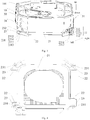
- a ceiling-embedded air conditioner 100 according to an embodiment of the present disclosure is described in detail below with reference to the accompanying drawings.
- the ceiling-embedded air conditioner 100 includes: an outer shell 10 and a drain pan 20.
- the outer shell 10 is provided therein with an accommodating cavity 101, and the bottom of the outer shell 10 is open.
- An evaporator, a fan assembly, an auxiliary heating member, and other parts may be mounted in the accommodating cavity 101.
- the bottom is open to communicate with the accommodating cavity 101, for convenient assembly of internal components.
- an outer circumferential side of the outer shell 10 is connected to a first fixing structure 11.
- the drain pan 20 is fitted at the bottom of the outer shell 10, and an outer circumferential side of the drain pan 20 is provided with a second fixing structure 231 connected to the first fixing structure 11.
- the drain pan 20 is fitted at one open side of the outer shell 10, so that the parts in the accommodating cavity 101 can be shielded and the sense of wholeness of the ceiling-embedded air conditioner 100 is enhanced.
- the drain pan 20 may collect condensate water that condenses on the components of the ceiling-embedded air conditioner 100 in a refrigeration mode, so as to prevent the condensate water from falling directly on the indoor floor to result in poor user experience.
- the first fixing structure 11 is provided with a first mounting hole 1121 and a prefixing groove 114.
- the second fixing structure 231 is provided with a second mounting hole 2311 and a prefixing hook 2312.
- the prefixing hook 2312 is clamped in the prefixing groove 114, the first mounting hole 1121 is aligned with the second mounting hole 2311.
- prefixing is formed between the prefixing hook 2312 and the prefixing groove 114, limit is formed between the first fixing structure 11 and the second fixing structure 231, and the first mounting hole 1121 and the second mounting hole 2311 of the two are aligned quickly to facilitate bolt fixing.
- the present disclosure enhances the strength of connection between the first fixing structure 11 and the second fixing structure 2312, thus forming a stable connection relationship between the drain pan 20 and the outer shell 10.
- the quick alignment of the first mounting hole 1121 and the second mounting hole 2311 improves the fitting efficiency between the first fixing structure 11 and the second fixing structure 2312, thereby greatly improving the assembly efficiency between the drain pan 20 and the outer shell 10.
- a plurality of first fixing structures 11 are provided, the plurality of first fixing structures 11 are disposed around the outer shell 10, and a plurality of second fixing structures 231 respectively corresponding to the plurality of the first fixing structures in an one-to-one manner are disposed around the drain pan 20.
- the plurality of first fixing structures 11 are disposed on the outer shell 10 respectively, which may increase connection points between the drain pan 20 and the outer shell 10, so that relatively stable connections are formed in all directions of the drain pan 20 and the outer shell 10, and a fitting surface difference between the drain pan 20 and the outer shell 10 can be reduced, thereby preventing excessively askew mounting of the drain pan 20.
- first fixing structures 11 are provided.
- the first fixing structures 11 are evenly spaced at four corners of the outer shell 10 respectively.
- the drain pan 20 is also provided with four second fixing structures 231 matching the first fixing structures 11.
- the number of the first fixing structures 11 and the number of the second fixing structures 231 may be selectively set according to an actual requirement, provided that stability and balance of the mounting and the aesthetics of the ceiling-embedded air conditioner 100 after mounting are ensured in case of no waste of costs and convenient quick mounting.
- the drain pan 20 is provided with a reinforcing rib 2313 at a junction with the first fixing structure 11.
- the setting of the reinforcing rib 2313 enhances local strength of the second fixing structure 231, prevents the crack of the second fixing structure 231 and the first fixing structure 11 due to fitting, and enhances the service life of the second fixing structure 231.
- reinforcing ribs are added around the second mounting hole 2311 to enhance the strength at the second mounting hole 2311.
- the first fixing structure 11 is a plate, and the first fixing structure 11 includes: a fitting section 111, a transverse extension section 112, and a vertical extension section 113.
- the fitting section 111 is connected to an outer circumferential surface of the outer shell 10.
- the fitting section 111 makes the first fixing structure 11 fitted stably on a side surface of the outer shell 10, which is not easy to fall off.
- the fitting section 111 further increases a fit area between the first fixing structure 11 and the outer shell 10.
- the fitting section 111 and the outer shell may be fixed by screw connection or welding connection.
- the transverse extension section 112 extends from the bottom of the fitting section 111 in a direction away from the outer shell 10, and the first mounting hole 1121 is disposed on the transverse extension section 112.
- the transverse extension section 112 provides the first mounting hole 1121 with a surface protruding beyond the outer shell 10, so that the first fixing structure 11 and the second fixing structure 231 are more convenient to mount and fit, which facilitates manual operations and is easy to observe.
- the first fixing structure 11 and the second fixing structure 231 do not affect the strength of the outer shell 10 and do not damage the outer shell 10.
- the vertical extension section 113 extends downward from a side of the transverse extension section 112 away from the fitting section 111.
- a horizontal width of the vertical extension section 113 is smaller than that of the transverse extension section 112, and a portion by which the vertical extension section 113 is shorter than the transverse extension section 112 constitutes the prefixing groove 114.
- a mounting groove is also formed between the vertical extension section 113 extending downward and the transverse extension section 112, which is convenient to cooperate with a mounting surface of the second fixing structure 231, so that the second fixing structure 231 is embedded in the mounting groove during prefixing, to accelerate the cooperation of the two.
- an obtuse angle is formed between the vertical extension section 113 and the transverse extension section 112, and a left side of the vertical extension section 113 matches a right side of the prefixing hook 2312.
- Such design facilitates quick pre-positioning.
- the second fixing structure 231 is fitted at the bottom of the transverse extension section 112, the prefixing hook 2312 is clamped at the prefixing groove 114, and the vertical extension section 113 is clamped on a side of the second fixing structure 231 away from the outer shell 10.
- the prefixing groove 114 makes it easy to form a clamping hook matching limit structure with the prefixing hook 2312.
- an upper surface of the transverse extension section 112 is provided with a convex edge 1122 surrounding the first mounting hole 1121, and the convex edge 1122 is integrally formed on the transverse extension section 112 by stamping.
- the convex edge 1122 on the one hand, can enhance the strength of the first mounting hole 1121, and on the other hand, also has a certain guiding effect, which facilitates guiding during mounting of bolts or screws.
- the vertical extension section 113 extends toward a direction away from the outer shell 10 to form another transverse extension section 112. This facilitates prefixing and limiting.
- the fitting section 111 on a side of the vertical extension section 113 shorter than the transverse extension section 112 is provided with a carrying plate 115.
- An upper surface of the carrying plate 115 is in contact with the second fixing structure 231, which may increase a supporting degree of a lower surface of the second fixing structure 231 and prevent an upper mounting hole from falling off after the fitting fails.
- the carrying plate 115 fits the vertical extension section 113 in a staggered manner. The carrying plate 115 may provide a certain guiding effect for the mounting of the second fixing structure 231.
- the prefixing hook 2312 is provided with a guide surface 2314 on a side toward the transverse extension section 112.
- the setting of the guide surface 2314 facilitates clamping the prefixing hook 2312 onto the prefixing groove 114.
- the drain pan 20 includes: a central pan 21, a plurality of circumferentially connected portions 23, and a plurality of connecting portions 22.
- the central pan 21 is disposed below an evaporator of the ceiling-embedded air conditioner 100, and is configured to receive water.
- an air inlet 211 is formed in the middle of the central pan 21, and annular flanges are formed around the air inlet 211.
- the plurality of circumferentially connected portions 23 are circumferentially spaced apart on an outer side of the central pan 21, the plurality of circumferentially connected portions 23 are connected below the insulating shell 30 and connected on an inner circumferential surface of the outer shell 10, and each of the circumferentially connected portions 23 is provided with the second fixing structure 231.
- the circumferentially connected portions 23 provide connection points for the second fixing structure 231, so that the second fixing structure 231 can match the transverse extension section 112.
- Each connecting portion 22 is connected between the central pan 21 and the circumferentially connected portions 23.
- the connecting portions 22 make the circumferentially connected portions 23 extend in an appropriate direction, and the central pan 21 does not need to be provided with the connecting portions 22 everywhere.
- an air outlet 102 in communication with the accommodating cavity 101 is formed between adjacent connecting portions 22, a side edge of the central pan 21, and the outer shell 10.
- the air outlet 22 may re-feed an air flow after heat exchange indoors.
- an inner side of the outer shell 10 is provided with an insulating shell 30 with the same shape as the outer shell 10, and the drain pan 20 is connected at the bottom of the insulating shell 30.
- a circumferential wall of the insulating shell 30 is provided with a plurality of joints 31, each of the joints 31 is open downward, and at least part of top surfaces of the joints 31 are arc-shaped surfaces, the circumferentially connected portions 23 are fitted in the joints 31, and top surfaces of the circumferentially connected portions 23 are closely fitted with the top surfaces of the joints 31.
- the top surfaces of the circumferentially connected portions 23 form a downward curved arc-shaped surface 232 at each of two circumferential ends.
- the curved arc-shaped surface 232 matches the joints 31, so that the drain pan 20 fits in with the outer shell 10, and the joints have good airtightness. This reduces the formation of condensation on the outer shell 10 of the ceiling-embedded air conditioner 100 in the refrigeration mode.
- the air in the accommodating cavity 101 and the air outside the ceiling-embedded air conditioner 100 are not easy to form an exchange region beyond the air inlet 211 and the air outlet 102.
- the structure of the ceiling-embedded air conditioner 100 in one specific embodiment of the present disclosure is described below with reference to Fig. 1 to Fig. 7 .
- the ceiling-embedded air conditioner 100 includes: an outer shell 10, a drain pan 20, and an insulating shell 30.
- the top of the outer shell 10 is mounted to the top of a wall, and the bottom of the outer shell 10 is provided with the drain pan 20.
- the outer shell 10 is provided with an accommodating cavity 101, one air inlet 211 in communication with the accommodating cavity 101 and four air outlets 102 in communication with the accommodating cavity 101 are formed on the drain pan 20.
- An inner side of the outer shell 10 is provided with the insulating shell 30 with the same shape as the outer shell 10, an outer circumferential side of the outer shell 10 is connected to four first fixing structures 11, and an outer circumferential side of the drain pan 20 is connected to a second fixing structure 231 connected to the first fixing structures 11.
- the first fixing structure 11 is a plate, and the first fixing structure 11 includes: a fitting section 111, a transverse extension section 112, and a vertical extension section 113.
- the fitting section 111 is connected to an outer circumferential surface of the outer shell 10
- the transverse extension section 112 extends from the bottom of the fitting section 111 in a direction away from the outer shell 10
- the first mounting hole 1121 is disposed on the transverse extension section 112.
- the vertical extension section 113 extends downward from a side of the transverse extension section 112 away from the fitting section 111.
- a horizontal width of the vertical extension section 113 is smaller than that of the transverse extension section 112, and a portion by which the vertical extension section 113 is shorter than the transverse extension section 112 constitutes the prefixing groove 114.
- the drain pan 20 includes: a central pan 21, four circumferentially connected portions 23, and eight connecting portions 22.
- the central pan 21 is disposed below an evaporator of the ceiling-embedded air conditioner 100, each connecting portion 22 is connected between the central pan 21 and the circumferentially connected portions 23, the plurality of circumferentially connected portions 23 are circumferentially spaced apart on an outer side of the central pan 21, the plurality of circumferentially connected portions 23 are connected below the insulating shell 30 and connected on an inner circumferential surface of the outer shell 10, and each circumferentially connected portion 23 is provided with the second fixing structure 231.
- Top surfaces of the circumferentially connected portions 23 form a downward curved arc-shaped surface 232 at each of two circumferential ends, and the curved arc-shaped surface 232 matches joints 31 on the insulating shell 30.
- the second fixing structure 231 is provided with a second mounting hole 2311 and a prefixing hook 2312.
- the prefixing hook 2312 is clamped in the prefixing groove 114, the first mounting hole 1121 is aligned with the second mounting hole 2311.
- a contact area between the drain pan 20 and the insulating shell 30 is small, the arc-shaped surface is fitted, and the sealing is tight.
- the ceiling-embedded air conditioner 100 of the present disclosure can reduce ground wire materials, isolate contact of wire bodies with foam, and have a high fireproofing grade.
- first and second may include one or more of this feature explicitly or implicitly, which are used to distinguish and describe features without distinction of order or importance.
- the terms “mounted”, “connected”, and “coupled” and the like are used broadly, and may be, for example, fixed connections, detachable connections, or integral connections; may also be mechanical or electrical connections; may also be direct connections or indirect connections via intervening structures; may also be inner communications of two elements.
- the above terms can be understood by those of ordinary skill in the art according to specific situations.
Landscapes
- Engineering & Computer Science (AREA)
- Chemical & Material Sciences (AREA)
- Combustion & Propulsion (AREA)
- Mechanical Engineering (AREA)
- General Engineering & Computer Science (AREA)
- Devices For Blowing Cold Air, Devices For Blowing Warm Air, And Means For Preventing Water Condensation In Air Conditioning Units (AREA)
- Housings, Intake/Discharge, And Installation Of Fluid Heaters (AREA)
- Removal Of Water From Condensation And Defrosting (AREA)
Applications Claiming Priority (2)
| Application Number | Priority Date | Filing Date | Title |
|---|---|---|---|
| CN201822114424.7U CN209325940U (zh) | 2018-12-14 | 2018-12-14 | 天花机 |
| PCT/CN2019/080044 WO2020118969A1 (fr) | 2018-12-14 | 2019-03-28 | Cassette de plafond |
Publications (2)
| Publication Number | Publication Date |
|---|---|
| EP3872410A1 true EP3872410A1 (fr) | 2021-09-01 |
| EP3872410A4 EP3872410A4 (fr) | 2022-01-05 |
Family
ID=67727039
Family Applications (1)
| Application Number | Title | Priority Date | Filing Date |
|---|---|---|---|
| EP19895016.4A Pending EP3872410A4 (fr) | 2018-12-14 | 2019-03-28 | Cassette de plafond |
Country Status (3)
| Country | Link |
|---|---|
| EP (1) | EP3872410A4 (fr) |
| CN (1) | CN209325940U (fr) |
| WO (1) | WO2020118969A1 (fr) |
Families Citing this family (2)
| Publication number | Priority date | Publication date | Assignee | Title |
|---|---|---|---|---|
| CN112032842B (zh) * | 2020-08-31 | 2022-07-12 | 青岛海尔空调电子有限公司 | 嵌入式空调器 |
| KR20240070650A (ko) * | 2021-11-23 | 2024-05-21 | 지디 미디어 히팅 엔드 벤틸레이팅 이큅먼트 코 엘티디 | 물받이 트레이 및 실내기 |
Family Cites Families (11)
| Publication number | Priority date | Publication date | Assignee | Title |
|---|---|---|---|---|
| CN2416405Y (zh) * | 2000-03-13 | 2001-01-24 | 大金工业株式会社 | 顶置式空调机 |
| KR100697194B1 (ko) * | 2001-06-25 | 2007-03-21 | 주식회사 엘지이아이 | 천정형 공기조화기의 드레인 팬 고정구조 |
| EP2023049B1 (fr) * | 2007-07-25 | 2013-10-30 | Sanyo Electric Co., Ltd. | Climatiseur de type d'assemblage au plafond et son unité intérieure |
| JP2009079819A (ja) * | 2007-09-26 | 2009-04-16 | Fujitsu General Ltd | 天井埋込形空気調和機 |
| CN201348314Y (zh) * | 2008-12-17 | 2009-11-18 | 广东美的电器股份有限公司 | 天花板嵌入式空调器的室内机 |
| JP6319064B2 (ja) * | 2014-11-28 | 2018-05-09 | 株式会社富士通ゼネラル | 天井埋込型空気調和機 |
| CN106403016B (zh) * | 2015-07-30 | 2019-07-26 | Lg电子株式会社 | 空调机的室内机 |
| CN106468459B (zh) * | 2015-08-11 | 2019-07-05 | Lg电子株式会社 | 空调机的室内机 |
| WO2018167894A1 (fr) * | 2017-03-15 | 2018-09-20 | 東芝キヤリア株式会社 | Unité intérieure pour climatiseur |
| CN207922398U (zh) * | 2018-02-27 | 2018-09-28 | 广东美的制冷设备有限公司 | 空调设备 |
| CN208186802U (zh) * | 2018-04-27 | 2018-12-04 | 广东美的制冷设备有限公司 | 接水盘及空调设备 |
-
2018
- 2018-12-14 CN CN201822114424.7U patent/CN209325940U/zh active Active
-
2019
- 2019-03-28 EP EP19895016.4A patent/EP3872410A4/fr active Pending
- 2019-03-28 WO PCT/CN2019/080044 patent/WO2020118969A1/fr unknown
Also Published As
| Publication number | Publication date |
|---|---|
| WO2020118969A1 (fr) | 2020-06-18 |
| CN209325940U (zh) | 2019-08-30 |
| EP3872410A4 (fr) | 2022-01-05 |
Similar Documents
| Publication | Publication Date | Title |
|---|---|---|
| US6471739B2 (en) | Dehumidifier housing | |
| EP3872410A1 (fr) | Cassette de plafond | |
| EP3748239A1 (fr) | Climatiseur de type conduit | |
| US9982908B2 (en) | Air conditioner | |
| US11378285B2 (en) | Outdoor unit for air conditioner and air conditioner | |
| JP6323203B2 (ja) | ダクト型空気調和機 | |
| CN210035719U (zh) | 室外机底盘结构及具有其的空调器 | |
| EP3598020B1 (fr) | Unité intérieure pour climatiseur | |
| JP4104629B2 (ja) | 天井埋込型空気調和装置 | |
| US20240255158A1 (en) | Heat exchanger sealing plate for air conditioner, indoor unit and air conditioner | |
| CN104359332A (zh) | 用于空调器的散热器和具有其的空调器 | |
| CN211119680U (zh) | 空调室内机 | |
| US11614257B2 (en) | Housing assembly for air handling apparatus and air handling apparatus | |
| CN110360743B (zh) | 用于空调室内机的安装组件 | |
| CN108613266B (zh) | 一种分离式风管机 | |
| US20210140651A1 (en) | Ceiling machine | |
| JP3863695B2 (ja) | 天井埋込型空気調和装置 | |
| CN210197604U (zh) | 空调器的电控组件及具有其的空调器 | |
| KR102049300B1 (ko) | 2방향 팬코일 유니트 | |
| EP4043806A1 (fr) | Climatiseur mobile | |
| CN221009900U (zh) | 贯流风机的电动机压盖、贯流风机和风管机 | |
| CN210118938U (zh) | 电控盒组件及具有其的空调器 | |
| CN215971035U (zh) | 一种蒸发箱 | |
| CN214501486U (zh) | 空调室外机 | |
| EP4368911A1 (fr) | Plateau de réception d'eau et unité intérieure |
Legal Events
| Date | Code | Title | Description |
|---|---|---|---|
| STAA | Information on the status of an ep patent application or granted ep patent |
Free format text: STATUS: THE INTERNATIONAL PUBLICATION HAS BEEN MADE |
|
| PUAI | Public reference made under article 153(3) epc to a published international application that has entered the european phase |
Free format text: ORIGINAL CODE: 0009012 |
|
| STAA | Information on the status of an ep patent application or granted ep patent |
Free format text: STATUS: REQUEST FOR EXAMINATION WAS MADE |
|
| 17P | Request for examination filed |
Effective date: 20210527 |
|
| AK | Designated contracting states |
Kind code of ref document: A1 Designated state(s): AL AT BE BG CH CY CZ DE DK EE ES FI FR GB GR HR HU IE IS IT LI LT LU LV MC MK MT NL NO PL PT RO RS SE SI SK SM TR |
|
| RAP3 | Party data changed (applicant data changed or rights of an application transferred) |
Owner name: GD MIDEA AIR-CONDITIONING EQUIPMENT CO., LTD. |
|
| A4 | Supplementary search report drawn up and despatched |
Effective date: 20211208 |
|
| RIC1 | Information provided on ipc code assigned before grant |
Ipc: F24F 3/00 20060101ALI20211202BHEP Ipc: F24F 13/22 20060101AFI20211202BHEP |
|
| DAV | Request for validation of the european patent (deleted) | ||
| DAX | Request for extension of the european patent (deleted) | ||
| GRAP | Despatch of communication of intention to grant a patent |
Free format text: ORIGINAL CODE: EPIDOSNIGR1 |
|
| STAA | Information on the status of an ep patent application or granted ep patent |
Free format text: STATUS: GRANT OF PATENT IS INTENDED |
|
| INTG | Intention to grant announced |
Effective date: 20240604 |
|
| GRAS | Grant fee paid |
Free format text: ORIGINAL CODE: EPIDOSNIGR3 |