EP3872377B1 - Ventil für ein kraftfahrzeug - Google Patents
Ventil für ein kraftfahrzeug Download PDFInfo
- Publication number
- EP3872377B1 EP3872377B1 EP20210850.2A EP20210850A EP3872377B1 EP 3872377 B1 EP3872377 B1 EP 3872377B1 EP 20210850 A EP20210850 A EP 20210850A EP 3872377 B1 EP3872377 B1 EP 3872377B1
- Authority
- EP
- European Patent Office
- Prior art keywords
- closure
- slide valve
- valve
- outlet
- permanent magnet
- Prior art date
- Legal status (The legal status is an assumption and is not a legal conclusion. Google has not performed a legal analysis and makes no representation as to the accuracy of the status listed.)
- Active
Links
Images

Classifications
-
- F—MECHANICAL ENGINEERING; LIGHTING; HEATING; WEAPONS; BLASTING
- F16—ENGINEERING ELEMENTS AND UNITS; GENERAL MEASURES FOR PRODUCING AND MAINTAINING EFFECTIVE FUNCTIONING OF MACHINES OR INSTALLATIONS; THERMAL INSULATION IN GENERAL
- F16K—VALVES; TAPS; COCKS; ACTUATING-FLOATS; DEVICES FOR VENTING OR AERATING
- F16K31/00—Actuating devices; Operating means; Releasing devices
- F16K31/02—Actuating devices; Operating means; Releasing devices electric; magnetic
- F16K31/06—Actuating devices; Operating means; Releasing devices electric; magnetic using a magnet, e.g. diaphragm valves, cutting off by means of a liquid
- F16K31/0603—Multiple-way valves
- F16K31/061—Sliding valves
-
- F—MECHANICAL ENGINEERING; LIGHTING; HEATING; WEAPONS; BLASTING
- F01—MACHINES OR ENGINES IN GENERAL; ENGINE PLANTS IN GENERAL; STEAM ENGINES
- F01P—COOLING OF MACHINES OR ENGINES IN GENERAL; COOLING OF INTERNAL-COMBUSTION ENGINES
- F01P7/00—Controlling of coolant flow
- F01P7/14—Controlling of coolant flow the coolant being liquid
-
- F—MECHANICAL ENGINEERING; LIGHTING; HEATING; WEAPONS; BLASTING
- F16—ENGINEERING ELEMENTS AND UNITS; GENERAL MEASURES FOR PRODUCING AND MAINTAINING EFFECTIVE FUNCTIONING OF MACHINES OR INSTALLATIONS; THERMAL INSULATION IN GENERAL
- F16K—VALVES; TAPS; COCKS; ACTUATING-FLOATS; DEVICES FOR VENTING OR AERATING
- F16K11/00—Multiple-way valves, e.g. mixing valves; Pipe fittings incorporating such valves
- F16K11/02—Multiple-way valves, e.g. mixing valves; Pipe fittings incorporating such valves with all movable sealing faces moving as one unit
- F16K11/06—Multiple-way valves, e.g. mixing valves; Pipe fittings incorporating such valves with all movable sealing faces moving as one unit comprising only sliding valves, i.e. sliding closure elements
- F16K11/065—Multiple-way valves, e.g. mixing valves; Pipe fittings incorporating such valves with all movable sealing faces moving as one unit comprising only sliding valves, i.e. sliding closure elements with linearly sliding closure members
- F16K11/0655—Multiple-way valves, e.g. mixing valves; Pipe fittings incorporating such valves with all movable sealing faces moving as one unit comprising only sliding valves, i.e. sliding closure elements with linearly sliding closure members with flat slides
-
- F—MECHANICAL ENGINEERING; LIGHTING; HEATING; WEAPONS; BLASTING
- F16—ENGINEERING ELEMENTS AND UNITS; GENERAL MEASURES FOR PRODUCING AND MAINTAINING EFFECTIVE FUNCTIONING OF MACHINES OR INSTALLATIONS; THERMAL INSULATION IN GENERAL
- F16K—VALVES; TAPS; COCKS; ACTUATING-FLOATS; DEVICES FOR VENTING OR AERATING
- F16K27/00—Construction of housing; Use of materials therefor
- F16K27/04—Construction of housing; Use of materials therefor of sliding valves
- F16K27/044—Construction of housing; Use of materials therefor of sliding valves slide valves with flat obturating members
-
- F—MECHANICAL ENGINEERING; LIGHTING; HEATING; WEAPONS; BLASTING
- F16—ENGINEERING ELEMENTS AND UNITS; GENERAL MEASURES FOR PRODUCING AND MAINTAINING EFFECTIVE FUNCTIONING OF MACHINES OR INSTALLATIONS; THERMAL INSULATION IN GENERAL
- F16K—VALVES; TAPS; COCKS; ACTUATING-FLOATS; DEVICES FOR VENTING OR AERATING
- F16K27/00—Construction of housing; Use of materials therefor
- F16K27/04—Construction of housing; Use of materials therefor of sliding valves
- F16K27/048—Electromagnetically actuated valves
-
- F—MECHANICAL ENGINEERING; LIGHTING; HEATING; WEAPONS; BLASTING
- F16—ENGINEERING ELEMENTS AND UNITS; GENERAL MEASURES FOR PRODUCING AND MAINTAINING EFFECTIVE FUNCTIONING OF MACHINES OR INSTALLATIONS; THERMAL INSULATION IN GENERAL
- F16K—VALVES; TAPS; COCKS; ACTUATING-FLOATS; DEVICES FOR VENTING OR AERATING
- F16K31/00—Actuating devices; Operating means; Releasing devices
- F16K31/02—Actuating devices; Operating means; Releasing devices electric; magnetic
- F16K31/06—Actuating devices; Operating means; Releasing devices electric; magnetic using a magnet, e.g. diaphragm valves, cutting off by means of a liquid
- F16K31/0603—Multiple-way valves
- F16K31/061—Sliding valves
- F16K31/0617—Sliding valves with flat slides
-
- F—MECHANICAL ENGINEERING; LIGHTING; HEATING; WEAPONS; BLASTING
- F16—ENGINEERING ELEMENTS AND UNITS; GENERAL MEASURES FOR PRODUCING AND MAINTAINING EFFECTIVE FUNCTIONING OF MACHINES OR INSTALLATIONS; THERMAL INSULATION IN GENERAL
- F16K—VALVES; TAPS; COCKS; ACTUATING-FLOATS; DEVICES FOR VENTING OR AERATING
- F16K37/00—Special means in or on valves or other cut-off apparatus for indicating or recording operation thereof, or for enabling an alarm to be given
- F16K37/0025—Electrical or magnetic means
- F16K37/0033—Electrical or magnetic means using a permanent magnet, e.g. in combination with a reed relays
-
- F—MECHANICAL ENGINEERING; LIGHTING; HEATING; WEAPONS; BLASTING
- F16—ENGINEERING ELEMENTS AND UNITS; GENERAL MEASURES FOR PRODUCING AND MAINTAINING EFFECTIVE FUNCTIONING OF MACHINES OR INSTALLATIONS; THERMAL INSULATION IN GENERAL
- F16K—VALVES; TAPS; COCKS; ACTUATING-FLOATS; DEVICES FOR VENTING OR AERATING
- F16K37/00—Special means in or on valves or other cut-off apparatus for indicating or recording operation thereof, or for enabling an alarm to be given
- F16K37/0025—Electrical or magnetic means
- F16K37/0041—Electrical or magnetic means for measuring valve parameters
-
- F—MECHANICAL ENGINEERING; LIGHTING; HEATING; WEAPONS; BLASTING
- F01—MACHINES OR ENGINES IN GENERAL; ENGINE PLANTS IN GENERAL; STEAM ENGINES
- F01P—COOLING OF MACHINES OR ENGINES IN GENERAL; COOLING OF INTERNAL-COMBUSTION ENGINES
- F01P7/00—Controlling of coolant flow
- F01P7/14—Controlling of coolant flow the coolant being liquid
- F01P2007/146—Controlling of coolant flow the coolant being liquid using valves
Definitions
- the invention relates to a valve for a motor vehicle, in particular for a coolant circuit in a motor vehicle, with a housing which has a cavity into which an inlet and an outlet open, wherein the inlet is connected to the outlet in an open state of the valve by a flow path running through the cavity, a valve opening arranged between the inlet and the outlet along the flow path in the cavity and a closure which is movable relative to the housing from a first position along an adjustment path into a second position, wherein the closure closes the valve opening in the first position to a lesser degree than in the second position.
- valves for motor vehicles have become known from the state of the art.
- EP 3 453 930 A1 a corresponding valve has become known which is also suitable for use in a coolant circuit of a motor vehicle.
- an armature is moved by means of an electromagnet under the influence of a spring force.
- this document proposes forming a permanent magnet on the closure and a magnetic field sensor in the cavity which detects a position of at least one closure.
- the object of the invention is to provide a valve of the type mentioned at the beginning, in which a state of the valve can be determined in a simple and at the same time precise manner during operation.
- a valve of the type mentioned at the outset in which a permanent magnet is connected to the closure, so that a movement of the closure along the adjustment path causes a movement of the Permanent magnets, whereby a sensor is arranged outside the cavity with which a position of the permanent magnet can be detected.
- a corresponding valve can basically be designed in a variety of ways. For example, such a valve can be designed as a slide valve, in which the closure moves along a sealing surface, or as a seat valve, in which the closure moves normal to the sealing surface.
- the permanent magnet is usually connected to the shutter in such a way that a movement of the shutter, in particular along the adjustment path, causes a movement of the permanent magnet.
- the permanent magnet can be connected to the shutter via a mechanism such as a gear.
- a particularly simple embodiment according to the invention is achieved if the permanent magnet is rigidly connected to the closure via a bracket. A movement of the permanent magnet then corresponds to a movement of the closure, so that by detecting the movement of the permanent magnet, the corresponding movement of the closure can be determined directly.
- an electromagnet is preferably provided with which the closure along the adjustment path is movable.
- the closure is designed as a plate-shaped component with openings, which is movable along a longitudinal direction or along an axis of a track of the electromagnet and is kinematically, in particular rigidly, connected to an armature of the electromagnet.
- the closure can be connected to the armature in any way possible, in particular force-fitting or form-fitting.
- a connection with play can also be provided, so that a movement of the armature along an axial direction of the electromagnet is not transmitted immediately when there is a change of direction, but only after the armature has moved a path predefined by the play in order to achieve favorable force ratios.
- a projection of the armature or a component rigidly connected to the armature, such as a sleeve can be provided, which engages in a corresponding recess in the closure, such as a window with play, and thus a movement of the armature is transmitted to the closure via the projection or the component and end stops in the recess.
- a spring can be provided against which an opening or closing movement of the closure takes place by means of the electromagnet, so that a defined position of the closure is ensured when the valve is de-energized.
- the at least one valve opening usually corresponds to a shape or contour of the closure, which can also have openings corresponding to the valve opening(s), so that the valve is closed when the valve opening(s) is/are covered by the closure.
- the valve is open when the closure does not cover the valve opening or when the one or more openings of the closure are brought into a position corresponding to the valve opening(s) by a corresponding movement of the closure. It can thus be provided that one or more openings of the closure in the first position of the closure are arranged directly at the valve opening or openings, so that a fluid flowing through the inlet into the cavity can flow through the opening of the closure and the valve opening leading into the outlet to the outlet. In the second position of the closure, a valve opening can be completely covered by the closure, so that no flow is possible through the corresponding valve opening.
- the valve can also be designed with an inlet and several outlets, wherein a first valve opening of a first outlet or a second valve opening of a second outlet is opened or closed depending on a position of the closure. By moving the closure along the adjustment path, a flow path from the inlet to a first outlet or to a second outlet can thus be created or blocked.
- the valve has an inlet, a first outlet and a second outlet, wherein a fluidic connection between the inlet and the first outlet and/or a fluidic connection between the inlet and the second outlet can be established and interrupted by a movement of the closure along the adjustment path.
- a valve is formed in a structurally simple manner with which a medium flowing through the inlet can be selectively guided into one of two outlets.
- a valve position can also be provided in which each outlet is closed so that no flow through the valve is possible.
- the closure in the first position closes one or more valve openings leading from the cavity into the second outlet and releases one or more valve openings leading from the cavity into the first outlet.
- the valve can be designed such that the closure in the second position releases one or more valve openings leading from the cavity into the second outlet and closes one or more valve openings leading from the cavity into the first outlet.
- a valve for example, in a coolant circuit, a The flow of a medium can be led either into a heat exchanger or a bypass line bridging the heat exchanger.
- a bypass line bridging the heat exchanger.
- at least two valve openings are provided per outlet, with which the inlet can be connected through the valve.
- the permanent magnet is arranged in the housing so that when a fluid flows from the inlet through the cavity to the outlet when the valve is open, the permanent magnet is surrounded by the fluid. It is therefore not necessary to introduce a passage into the housing with which a movement of the closure is transmitted from the inside of the housing or from the cavity to the outside. This completely eliminates the need for complex sealing of such a passage.
- the senor is arranged on the outside of the housing so that when a fluid flows from the inlet through the cavity to the outlet with the valve open, the sensor is not washed around by the fluid. This achieves a particularly accurate measurement result and a long service life for the sensor.
- the housing is made of a non-magnetizable material, in particular a plastic or a metal, preferably aluminum.
- a position of the permanent magnet, which can be located in the housing, can then also be determined with high accuracy using a sensor arranged outside the housing.
- the permanent magnet is positioned in the cavity in such a way that, when the valve is open, it is arranged outside a direct connection between the inlet and outlet. Low flow speeds are thus achieved at the magnet, which ensures a particularly long service life thanks to particularly low abrasive wear.
- the permanent magnet is positioned at the end in the cavity in a lateral recess.
- the permanent magnet is positioned off-center, especially since there are usually particularly low flow speeds there.
- the permanent magnets arranged in the cavity are attached via a rigid bracket.
- the permanent magnet is arranged in the cavity in such a way that the permanent magnet is less than 10 mm, in particular less than 5 mm, away from the housing in every possible position of the closure when the valve is in operation.
- a correspondingly small distance ensures a good measurement result.
- a small distance is therefore advantageous for an accurate measurement result, a minimal distance between the housing and the permanent magnet also ensures that the permanent magnet does not slide on the housing when the closure moves, which would reduce the service life.
- the permanent magnet is therefore usually spaced away from the housing in every operating position of the closure.
- the senor is arranged on the outside of the housing at a position corresponding to a position of the permanent magnet.
- the sensor is then arranged at a minimal distance from the permanent magnet despite being positioned outside the housing, so that a movement of the permanent magnet, in particular parallel to the adjustment path, can be detected particularly precisely.
- the sensor is preferably arranged at a distance of less than 5 mm from the housing.
- the sensor can also be glued to the housing, for example using a potting compound such as a resin.
- a distance between the permanent magnet and the sensor is less than 15 mm, according to the invention less than 10 mm, in every possible position of the closure during operation of the valve. This allows the position of the permanent magnet with the sensor to be determined particularly precisely, even through a housing wall and over the entire adjustment path.
- the senor has a Hall sensor or is formed by a Hall sensor. In this way, the position of the permanent magnet can be determined particularly precisely, even through the housing.
- An output voltage of a sensor with which a position of a permanent magnet can be detected in particular a Hall sensor, often cannot be processed further directly in a vehicle's electronics. It can therefore be advantageous if electronics are connected downstream of the Hall sensor or if the Hall sensor is part of an integrated circuit with which an output voltage that can be further processed as required can be generated based on an output signal from the sensor.
- the sensor can be arranged in a sensor module, which can also contain appropriate electronics in addition to the sensor.
- an electrical output signal of a sensor module containing the sensor corresponds to a predefined first voltage when the valve is closed.
- This voltage can be, for example, between 0.5 volts and 1.0 volts, typically 0.75 volts.
- an electrical output signal of a sensor module containing the sensor corresponds to a predefined second voltage when the valve is open.
- This second voltage usually differs from the first voltage and can be, for example, between 4.0 volts and 4.5 volts, typically in the range of about 4.25 volts.
- the sensor module can, for example, contain the sensor and an electronic component with which an electrical output voltage of the sensor can be amplified and shifted relative to a zero point in order to achieve targeted output voltages of the sensor module under certain valve states.
- Voltages defined in this way can be achieved, for example, as part of a calibration, which can be carried out, for example, as part of a production, quality or functional test.
- a voltage measured during operation between the predefined first voltage and the predefined second voltage can then be used to determine a relationship between a current actual position of the shutter and the measured voltage, which relationship can be linear, at each position of the shutter via a Output voltage of the sensor module can be used to determine the position of the shutter.
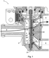
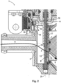
- Fig. 1 to 3 show a valve 1 according to the invention designed as a slide valve in a sectional view, wherein Fig. 1 shows the valve 1 in a first operating state, in which an inlet 4 of the valve 1 is fluidically connected to a first outlet 5 of the valve 1, while Fig. 2 shows the valve 1 in a second operating state, in which the inlet 4 is fluidically connected to a second outlet 6, but there is no fluidic connection between the inlet 4 and the first outlet 5.
- valve 1 can also be designed with only one outlet 5, 6, more than one inlet 4 and/or more than two outlets 5, 6.
- the valve 1 shown has, as can be seen, an inlet 4 and two outlets 5, 6 which open into a cavity 3.
- a sealing seat 13 with valve openings 7 is arranged between the cavity 3 and the first outlet 5 and between the cavity 3 and the second outlet 6, wherein valve openings 7 opening into the first outlet 5 as well as valve openings 7 opening into the second outlet 6 are provided.
- a plate-shaped closure 8 is positioned in the cavity 3, which can be moved translationally along an axial direction over an adjustment path by means of an electromagnet, which closure 8 has openings 17 and is rigidly connected to an armature 12 of the electromagnet.
- a movement of the armature 12, which is caused by energizing a coil of the Electromagnet can be triggered, is transmitted to the closure 8 via a positive connection.
- the armature 12 and the closure 8 are positioned in a plane normal to a direction of movement or normal to a direction of an axis 21 of the armature 12 in the housing 2 such that the armature 12 and the closure 8 can only move freely along the direction of movement or along the axis 21 relative to the housing, and a sleeve 19 connected to the armature 12 engages in a window 20 of the closure 8 in order to transmit a force in the axial direction or parallel to the adjustment path from the armature 12 to the closure 8.
- the window 20 is larger here, as shown, than an engaging part of the sleeve 19, so that the positive force transmission takes place with play, in that the sleeve 19 rests against one of two stops 22 of the window 20 depending on the direction of movement.
- a spring 16 is positioned between the armature 12 and a core 11 of the electromagnet in order to achieve a favorable force curve during a switching process.
- a fluidic connection is provided from the inlet 4 via the openings 17 of the closure 8 and the valve openings 7, which open into the first outlet 5.
- a flow path 18 is shown which runs from the inlet 4 through the cavity 3 and one of the openings 17 of the closure 8 and one of the valve openings 7 opening into the first outlet 5, along which a medium can flow from the inlet 4 to the first outlet 5.
- valve openings 7 of the sealing seat 13 leading into the second outlet 6 are closed by the closure 8 in the first operating state, so that there is no fluidic connection between the inlet 4 and the second outlet 6.
- the closure 8 is thus in the Fig. 1 illustrated first operating state in a first extreme position in which the valve openings 7 opening into the first outlet 5 are completely open and the valve openings 7 opening into the second outlet 6 are closed.
- Fig. 2 In the second operating state shown, in which the closure 8 is in the second position, those valve openings 7 of the sealing seat 13 which open into the first outlet 5 are closed by the closure 8, and the valve openings 7 of the sealing seat 13 which open into the second outlet 6 are released by the closure 8 or an opening 17 of the closure 8, so that a fluidic connection is provided between the inlet 4 and the second outlet 6 via the valve openings 7 which open into the second outlet 6.
- an open flow path 18 is shown which runs from the inlet 4 through the cavity 3 and one of the openings 17 of the closure 8 and a valve opening 7 which opens into the second outlet 6, along which a medium can flow from the inlet 4 to the second outlet 6.
- the closure 8 is thus in the Fig. 2 illustrated second operating state in a second extreme position in which the valve openings 7 opening into the first outlet 5 are completely closed and the valve openings 7 opening into the second outlet 6 are completely open.
- a permanent magnet 9 is provided in the cavity 3, which is kinematically, here rigidly, connected to the closure 8.
- the permanent magnet 9 is arranged at an upper end of the cavity 3 in a lateral recess 15, so that it neither hinders a flow through the cavity 3 nor does a magnetic field of the permanent magnet 9, usually a cooling liquid such as water, possibly with appropriate additives, become influenced by the flow. Furthermore, only a low flow speed is usually achieved at the corresponding position, which results in favorable wear.
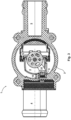
- the permanent magnet 9 is connected to the closure 8 via a bracket 14, which is inserted into the Fig. 1 and Fig. 2 is only partially visible, especially since it lies partly outside the cutting plane running through a longitudinal axis of the electromagnet, as can be seen from Fig. 3 results.
- a sensor module 10 is arranged on the outside of the housing 2, which is designed as an integrated circuit with a Hall sensor. With this sensor module 10, a position of the magnetic field caused by the permanent magnet 9 can be detected through the housing 2, which in the embodiment shown is made of aluminum is formed, but can of course also be made of another material such as a plastic.
- the sensor module 10 can be connected to the housing 2 by means of a casting compound such as a resin in order to achieve a stable and robust connection. Alternatively or additionally, the sensor module 10 can also be connected to the housing 2 in a form-fitting and/or force-fitting manner, in particular by means of a screw connection.
- the sensor module 10 can, for example, be calibrated in such a way that it Fig. 1 In the first operating state shown, i.e. when there is a fluidic connection from the inlet 4 to the first outlet 5 and a fluidic connection from the inlet 4 to the second outlet 6 is closed, an electrical voltage of about 0.75 volts is output and in the Fig. 2 In the second operating state shown, i.e. when a fluidic connection from the inlet 4 to the first outlet 5 is closed and a fluidic connection from the inlet 4 to the second outlet 6 exists, an electrical voltage of about 4.25 volts is output, so that it is easy to electronically determine in which operating state the valve 1 is or also a position of the closure 8 between the positions shown in Fig. 1 and Fig. 2 shown extreme positions along the adjustment path can be detected. A current actual position of the shutter 8 between the first operating state and the second operating state can be determined, for example, via a linear relationship between the output voltage of the sensor module and the actual position.
- These voltages are calibrated using electronics connected downstream of the Hall sensor in the sensor module 10, with which an output voltage of the Hall sensor can be amplified and shifted relative to a reference potential or a zero point in order to be able to output defined voltages when the valve 1 is closed and open, regardless of manufacturing tolerances or an actual distance between the permanent magnet 9 and the Hall sensor, which can be further processed in vehicle electronics.
- the calibration of the sensor module 10 can be carried out, for example, as part of a functional test after the valve 1 has been manufactured.
- Fig. 3 shows a top view of the already in Fig. 1 and Fig. 2 illustrated valve 1.
- the permanent magnet 9 is connected to the closure 8 via a bracket 14 and is positioned off-center in the cavity 3, so that the flow velocity in the area of the permanent magnet 9 is low.
- Fig. 4 shows an armature 12 of a valve 1 according to the invention together with a closure 8 connected to it, wherein a connection between armature 12 and closure 8 in the direction of an axis 21 of the electromagnet or in the direction of movement for transmitting a movement is made here in a form-fitting manner via a sleeve 19 engaging in a window 20 of the closure 8, which sleeve 19 is rigidly connected to the armature 12 or is a part of the armature 12.
- the sleeve 19 can basically also be positioned with a clearance in the window 20, so that when the armature 12 moves from an extreme position in a direction of the axis 21, initially only the armature 12 together with the sleeve 19 is moved until the sleeve 19 is moved across a width of the window 20 in the axial direction, and thus rests at the end in the window 20 against a stop 22 of the window 20, so that when the armature 12 moves further in the corresponding direction, the closure 8 is moved by the sleeve 19 engaging in the window 20 or resting against a stop 22 of the window 20.
- the closure 8 is essentially plate-shaped and the openings 17 in the closure 8, which correspond to the valve openings 7 depending on the position of the closure 8, are approximately rectangular. Furthermore, in Fig. 4 It can be seen that the permanent magnet 9 is connected to the armature 12 via a bracket 14, so that the permanent magnet 9, as already shown in Fig. 1 and Fig. 2 shown is arranged close to a housing wall during operation in order to achieve an accurate measurement result despite the sensor module 10 arranged on the outside of the housing 2.
- valve 1 designed as a slide valve
- the closure 8 is thus moved essentially along a sealing surface of the sealing seat 13 and normal to a flow
- a valve 1 according to the invention can of course also be designed with a closure 8 or sealing body that is not moved along a sealing surface and/or approximately along the flow, for example as a seat valve.
- valve 1 With a valve 1 according to the invention, the current position of the closure 8 or a valve position can be determined in a simple and at the same time robust and precise manner over the entire adjustment path, even during operation.
- a corresponding valve 1 can basically be used in a wide variety of areas.
- a corresponding valve 1 is preferably used for a motor vehicle, in particular in a coolant circuit of a motor vehicle.
Landscapes
- Engineering & Computer Science (AREA)
- General Engineering & Computer Science (AREA)
- Mechanical Engineering (AREA)
- Chemical & Material Sciences (AREA)
- Combustion & Propulsion (AREA)
- Physics & Mathematics (AREA)
- Electromagnetism (AREA)
- Magnetically Actuated Valves (AREA)
- Indication Of The Valve Opening Or Closing Status (AREA)
Description
- Die Erfindung betrifft ein Ventil für ein Kraftfahrzeug, insbesondere für einen Kühlmittelkreislauf in einem Kraftfahrzeug, mit einem Gehäuse, welches einen Hohlraum aufweist, in welchen ein Einlass und ein Auslass münden, wobei der Einlass mit dem Auslass in einem geöffneten Zustand des Ventils durch einen durch den Hohlraum verlaufenden Strömungspfad verbunden ist, einer zwischen dem Einlass und dem Auslass entlang des Strömungspfades im Hohlraum angeordneten Ventilöffnung und einem Verschluss, welcher relativ zum Gehäuse von einer ersten Position entlang eines Verstellweges in eine zweite Position bewegbar ist, wobei der Verschluss die Ventilöffnung in der ersten Position zu einem geringeren Grad als in der zweiten Position verschließt.
- Aus dem Stand der Technik sind verschiedene Ventile für Kraftfahrzeuge bekannt geworden. Beispielsweise ist aus dem Dokument
EP 3 453 930 A1 ein entsprechendes Ventil bekannt geworden, welches auch für den Einsatz in einem Kühlmittelkreislauf eines Kraftfahrzeuges geeignet ist. Bei einem solchen Ventil wird ein Anker mittels eines Elektromagneten unter Einwirkung einer Federkraft bewegt. Um eine tatsächliche Ist-Position des Ankers bestimmen zu können, wird nach diesem Dokument vorgeschlagen, am Verschluss einen Permanentmagnet und im Hohlraum einen Magnetfeldsensor auszubilden, der eine Position des zumindest einen Verschlusses erfasst. - Es hat sich allerdings gezeigt, dass ein entsprechender Aufbau nur mit hohem Aufwand herstellbar ist und zudem nur eine geringe Messgenauigkeit erreicht wird, sodass eine Position des Verschlusses bzw. eine Stellung des Ventils nur mit geringer Genauigkeit erfassbar ist.
- Hier setzt die Erfindung an. Aufgabe der Erfindung ist es, ein Ventil der eingangs genannten Art anzugeben, bei welchem ein Zustand des Ventils auf einfache und gleichzeitig genaue Weise während eines Betriebes bestimmbar ist.
- Diese Aufgabe wird erfindungsgemäß durch ein Ventil der eingangs genannten Art gelöst, bei welchem mit dem Verschluss ein Permanentmagnet verbunden ist, sodass eine Bewegung des Verschlusses entlang des Verstellweges eine Bewegung des Permanentmagneten bewirkt, wobei außerhalb des Hohlraumes ein Sensor angeordnet ist, mit welchem eine Position des Permanentmagneten erfassbar ist.
- Im Rahmen der Erfindung wurde erkannt, dass ein hoher Aufwand bei der Herstellung genauso wie eine geringe Genauigkeit der mit dem Sensor erfassten Position vermieden werden können, wenn der Sensor nicht wie im Stand der Technik vorgeschlagen im Hohlraum angeordnet, sondern außerhalb des Hohlraumes positioniert wird. So ist dann auf einfache Weise ausgeschlossen, dass ein durch das Ventil strömendes Fluid, insbesondere eine Kühlflüssigkeit, den Sensor umspült und somit ein Messergebnis verfälscht. Weiter ist es bei einer Positionierung des Sensors außerhalb des Hohlraumes auch nicht erforderlich, Datenleitungen des Sensors aus dem Hohlraum, welcher bei geöffnetem Ventil von Fluid durchströmt wird, aus dem Hohlraum hinaus zu führen, wodurch Öffnungen im Gehäuse für die Datenleitungen vermieden werden, welche wiederum auf aufwendige Weise gegenüber dem Fluid abgedichtet werden müssten. Weiter wird dadurch eine genaue Positionsbestimmung des Verschlusses über den gesamten Verstellweg erreicht. Ein entsprechendes Ventil kann grundsätzlich auf verschiedenste Weisen ausgebildet sein. Beispielsweise kann ein solches Ventil als Schieberventil, bei welchem sich der Verschluss entlang einer Dichtfläche bewegt, oder als Sitzventil, bei welchem sich der Verschluss normal zur Dichtfläche bewegt, ausgebildet sein.
- Der Permanentmagnet ist in der Regel derart mit dem Verschluss verbunden, dass eine Bewegung des Verschlusses, insbesondere entlang des Verstellweges, eine Bewegung des Permanentmagneten bewirkt. Hierzu kann der Permanentmagnet über einen Mechanismus wie beispielsweise ein Getriebe mit dem Verschluss verbunden sein.
- Eine besonders einfache erfindungsgemäße Ausführung wird erreicht, wenn der Permanentmagnet mit dem Verschluss über einen Bügel starr verbunden ist. Eine Bewegung des Permanentmagneten entspricht dann einer Bewegung des Verschlusses, sodass durch ein Erfassen der Bewegung des Permanentmagneten unmittelbar auf die entsprechende Bewegung des Verschlusses geschlossen werden kann.
- Um ein zuverlässiges Betätigen des Ventils zu gewährleisten, ist bevorzugt ein Elektromagnet vorgesehen, mit welchem der Verschluss entlang des Verstellweges bewegbar ist. Der Verschluss ist als plattenförmiges Bauteil mit Öffnungen ausgebildet, welches entlang einer Längsrichtung bzw. entlang einer Achse einer Spur des Elektromagneten bewegbar und kinematisch, insbesondere starr, mit einem Anker des Elektromagneten verbunden ist.
- Der Verschluss kann mit dem Anker grundsätzlich auf jede mögliche Weise verbunden sein, insbesondere kraft- oder formschlüssig. Dabei kann auch eine Verbindung mit Spiel vorgesehen sein, sodass eine Bewegung des Ankers entlang einer Achsrichtung des Elektromagneten bei einem Richtungswechsel nicht unmittelbar, sondern erst nach Bewegung des Ankers um einen durch das Spiel vordefinierten Weg übertragen wird, um günstige Kraftverhältnisse zu erreichen. Hierzu kann beispielsweise eine Auskragung des Ankers oder ein mit dem Anker starr verbundenes Bauteil wie beispielsweise eine Hülse vorgesehen sein, welche in eine korrespondierende Ausnehmung des Verschlusses wie beispielsweise ein Fenster mit Spiel eingreift und somit eine Bewegung des Ankers über die Auskragung bzw. das Bauteil und endseitige Anschläge in der Ausnehmung auf den Verschluss übertragen wird. Dadurch wird bei einer Bewegung aus einer Extremposition zunächst nur der Anker und, erst nachdem das Spiel überwunden ist, bzw. die Auskragung oder das Bauteil an einem Anschlag anliegt auch der Verschluss bewegt, sodass die bei Beginn der Bewegung zu beschleunigenden Massen reduziert sind.
- Weiter kann eine Feder vorgesehen sein, gegen welche eine Öffnungs- oder Schließbewegung des Verschlusses mittels des Elektromagneten erfolgt, sodass in einem stromlosen Zustand des Ventils eine definierte Position des Verschlusses gewährleistet ist.
- Die zumindest eine Ventilöffnung korrespondiert üblicherweise mit einer Form bzw. Kontur des Verschlusses, welcher hierzu auch mit der bzw. den Ventilöffnungen korrespondierende Öffnungen aufweisen kann, sodass das Ventil geschlossen ist, wenn die Ventilöffnung bzw. die Ventilöffnungen durch den Verschluss bedeckt ist bzw. sind. Analog ist das Ventil dann geöffnet, wenn der Verschluss die Ventilöffnung nicht bedeckt bzw. wenn die eine oder mehreren Öffnungen des Verschlusses durch eine entsprechende Bewegung des Verschlusses in eine mit der bzw. den Ventilöffnungen korrespondierende Position gebracht sind. Es kann somit vorgesehen sein, dass eine oder mehrere Öffnungen des Verschlusses in der ersten Position des Verschlusses unmittelbar an der Ventilöffnung bzw. den Ventilöffnungen angeordnet sind, sodass ein durch den Einlass in den Hohlraum strömendes Fluid durch die Öffnung des Verschlusses und die in den Auslass mündende Ventilöffnung zum Auslass strömen kann. In der zweiten Position des Verschlusses kann eine Ventilöffnung gänzlich durch den Verschluss bedeckt sein, sodass keine Strömung durch die entsprechende Ventilöffnung möglich ist.
- Das Ventil kann auch mit einem Einlass und mehreren Auslässen ausgebildet sein, wobei abhängig von einer Position des Verschlusses eine erste Ventilöffnung eines ersten Auslasses oder eine zweite Ventilöffnung eines zweiten Auslasses geöffnet bzw. verschlossen sind. Durch eine Verschiebung des Verschlusses entlang des Verstellweges kann somit ein Strömungspfad vom Einlass zu einem ersten Auslass oder zu einem zweiten Auslass geschaffen bzw. blockiert werden.
- Beispielsweise kann vorgesehen sein, dass das Ventil einen Einlass, einen ersten Auslass und einen zweiten Auslass aufweist, wobei durch eine Bewegung des Verschlusses entlang des Verstellweges eine fluidische Verbindung des Einlasses mit dem ersten Auslass und/oder eine fluidische Verbindung des Einlasses mit dem zweiten Auslass herstellbar und unterbrechbar ist. Somit ist auf konstruktiv einfache Weise ein Ventil gebildet, mit welchem ein durch den Einlass strömendes Medium wahlweise in einen von zwei Auslässen geleitet werden kann. Dabei kann auch eine Ventilstellung vorgesehen sein, in welcher jeder Auslass verschlossen ist, sodass keine Strömung durch das Ventil möglich ist.
- Um dabei einen besonders einfachen Aufbau zu erreichen, kann vorgesehen sein, dass der Verschluss in der ersten Position eine oder mehrere vom Hohlraum in den zweiten Auslass mündende Ventilöffnungen verschließt und eine oder mehrere vom Hohlraum in den ersten Auslass mündende Ventilöffnungen freigibt. Analog kann das Ventil derart ausgebildet sein, dass der Verschluss in der zweiten Position eine oder mehrere vom Hohlraum in den zweiten Auslass mündende Ventilöffnungen freigibt und eine oder mehrere vom Hohlraum in den ersten Auslass mündende Ventilöffnungen verschließt. Mit einer Bewegung des Verschlusses von der ersten Position in die zweite Position kann somit eine Strömung vom Einlass durch den Hohlraum zum ersten Auslass beendet und eine Strömung vom Einlass durch den Hohlraum zum zweiten Auslass freigegeben werden. Mit einem derartigen Ventil kann beispielsweise in einem Kühlmittelkreislauf eine Strömung eines Mediums wahlweise in einen Wärmetauscher oder eine den Wärmetauscher überbrückende Bypass-Leitung geführt werden. Um günstige Strömungsverhältnisse im Ventil zu erreichen, sind bevorzugt zumindest zwei Ventilöffnungen je Auslass vorgesehen, mit welchem der Einlass durch das Ventil verbindbar ist.
- Günstig ist es, wenn der Permanentmagnet im Gehäuse angeordnet ist, sodass der Permanentmagnet dann, wenn ein Fluid bei geöffnetem Ventil vom Einlass durch den Hohlraum zum Auslass strömt, vom Fluid umspült wird. Es ist somit nicht erforderlich, einen Durchlass in das Gehäuse einzubringen, mit welchem eine Bewegung des Verschlusses von einem Inneren des Gehäuses bzw. vom Hohlraum aus zu einem Äußeren übertragen wird. Dadurch entfällt eine aufwendige Abdichtung eines solchen Durchlasses gänzlich.
- Bevorzugt ist der Sensor außen am Gehäuse angeordnet, sodass der Sensor dann, wenn ein Fluid bei geöffnetem Ventil vom Einlass durch den Hohlraum zum Auslass strömt, vom Fluid nicht umspült wird. Dadurch werden ein besonders genaues Messergebnis sowie eine lange Standzeit des Sensors erreicht.
- Zur Erreichung eines Messergebnisses mit hoher Genauigkeit ist es günstig, wenn das Gehäuse aus einem nicht magnetisierbaren Material, insbesondere einem Kunststoff oder einem Metall, bevorzugt Aluminium, besteht. Es kann dann auch mit einem außerhalb des Gehäuses angeordneten Sensor eine Position des Permanentmagneten, welcher sich im Gehäuse befinden kann, mit hoher Genauigkeit bestimmt werden. Um ein besonders genaues Messergebnis zu erreichen, ist es bevorzugt vorgesehen, dass der Permanentmagnet derart im Hohlraum positioniert ist, dass dieser bei geöffnetem Ventil außerhalb einer direkten Verbindung von Einlass und Auslass angeordnet ist. Somit werden am Magnet geringe Strömungsgeschwindigkeiten erreicht, wodurch über einen besonders geringen abrasiven Verschleiß eine besonders lange Standzeit gegeben ist. Erfindungsgemäß ist der Permanentmagnet endseitig im Hohlraum in einer seitlichen Aussparung positioniert. Insbesondere ist der Permanentmagnet außermittig positioniert, zumal dort üblicherweise besonders geringere Strömungsgeschwindigkeiten vorliegen. Eine Verbindung des in der Regel mittig im Hohlraum angeordneten Verschlusses mit dem in der Regel endseitig im Hohlraum angeordneten Permanentmagneten erfolgt über einen starren Bügel.
- Um ein besonders genaues Messergebnis zu erhalten, ist der Permanentmagnet derart im Hohlraum angeordnet, dass der Permanentmagnet in jeder bei einem Betrieb des Ventils möglichen Position des Verschlusses einen Abstand zum Gehäuse von weniger als 10 mm, insbesondere weniger als 5 mm, aufweist. Ein entsprechend geringer Abstand gewährleistet ein gutes Messergebnis. Wenngleich somit ein geringer Abstand vorteilhaft für ein genaues Messergebnis ist, ist gleichzeitig durch einen minimalen Abstand zwischen dem Gehäuse und dem Permanentmagnet auch sichergestellt, dass der Permanentmagnet bei einer Bewegung des Verschlusses nicht am Gehäuse gleitet, wodurch eine Standzeit verringert werden würde. Der Permanentmagnet ist daher üblicherweise in jeder Betriebsposition des Verschlusses vom Gehäuse beabstandet.
- Zur Erreichung einer kompakten Bauweise und eines Messergebnisses mit hoher Genauigkeit, ist es ferner vorteilhaft, wenn der Sensor außen am Gehäuse an einer mit einer Position des Permanentmagneten korrespondierenden Position angeordnet ist. Der Sensor ist dann trotz Positionierung außerhalb des Gehäuses mit minimalem Abstand zum Permanentmagnet angeordnet, sodass eine Bewegung des Permanentmagneten, insbesondere parallel zum Verstellweg, besonders genau erfasst werden kann. Bevorzugt ist der Sensor mit einem Abstand zum Gehäuse von weniger als 5 mm angeordnet. Der Sensor kann mit dem Gehäuse auch verklebt sein, beispielsweise über eine Vergussmasse wie ein Harz.
- Mit Vorteil ist vorgesehen, dass ein Abstand zwischen dem Permanentmagneten und dem Sensor in jeder bei einem Betrieb des Ventils möglichen Position des Verschlusses weniger als 15 mm, erfindungsgemäß weniger als 10 mm, beträgt. Dadurch lässt sich die Position des Permanentmagneten mit dem Sensor auch durch eine Gehäusewand hindurch und über den gesamten Verstellweg besonders genau bestimmen.
- Es hat sich bewährt, dass der Sensor einen Hall-Sensor aufweist oder durch einen Hall-Sensor gebildet ist. Auf diese Weise kann die Position des Permanentmagneten auch durch das Gehäuse hindurch besonders genau bestimmt werden.
- Eine Ausgangsspannung eines Sensors, mit welchem eine Position eines Permanentmagneten erfassbar ist, insbesondere eines Hall-Sensors, kann häufig nicht unmittelbar in einer Fahrzeugelektronik weiterverarbeitet werden. Es kann daher günstig sein, wenn dem Hall-Sensor eine Elektronik nachgeschaltet oder der Hall-Sensor Teil eines integrierten Schaltkreises ist, mit welchem basierend auf einem Ausgangssignal des Sensors eine beliebig weiter verarbeitbare Ausgangsspannung erzeugbar ist. Hierzu kann der Sensor in einem Sensormodul angeordnet sein, welches neben dem Sensor auch eine entsprechende Elektronik enthalten kann.
- Um das Ventil besonders einfach in ein Fahrzeug mit gegebener Bordelektronik einbinden zu können, ist bevorzugt vorgesehen, dass ein elektrisches Ausgangssignal eines Sensormoduls, welches den Sensor enthält, bei geschlossenem Ventil einer vordefinierten ersten Spannung entspricht. Diese Spannung kann beispielsweise zwischen 0,5 Volt und 1,0 Volt, typischerweise 0,75 Volt, betragen.
- Es ist dann bevorzugt vorgesehen, dass ein elektrisches Ausgangssignal eines Sensormoduls, welches den Sensor enthält, bei geöffnetem Ventil einer vordefinierten zweiten Spannung entspricht. Diese zweite Spannung unterscheidet sich üblicherweise von der ersten Spannung und kann beispielsweise zwischen 4,0 Volt und 4,5 Volt, typischerweise im Bereich von etwa 4,25 Volt, liegen.
- Das Sensormodul kann beispielsweise den Sensor und ein Elektronikbauteil enthalten, mit welchem eine elektrische Ausgangsspannung des Sensors verstärkt und relativ zu einem Nullpunkt verschoben werden kann, um gezielte Ausgangsspannungen des Sensormoduls bei bestimmten Ventilzuständen zu erreichen.
- Derart definierte Spannungen können beispielsweise im Rahmen einer Kalibrierung erreicht werden, welche beispielsweise im Rahmen einer Herstellung, einer Qualitäts- oder Funktionsprüfung erfolgen kann. Über eine zwischen der vordefinierten ersten Spannung und der vordefinierten zweiten Spannung liegende, bei einem Betrieb gemessene Spannung kann dann über einen Zusammenhang zwischen einer aktuellen Ist-Position des Verschlusses und der gemessenen Spannung, welcher Zusammenhang beispielsweise linear sein kann, an jeder Position des Verschlusses über eine Ausgangsspannung des Sensormoduls auf die Position des Verschlusses geschlossen werden.
- Weitere Merkmale, Vorteile und Wirkungen der Erfindung ergeben sich anhand des nachfolgend dargestellten Ausführungsbeispiels. In den Zeichnungen, auf welche dabei Bezug genommen wird, zeigen:
-
Fig. 1 und2 ein erfindungsgemäß ausgebildetes Ventil in unterschiedlichen Betriebszuständen; -
Fig. 3 eine weitere Ansicht eines erfindungsgemäßen Ventils; -
Fig. 4 ein Detail eines erfindungsgemäßen Ventils. -
Fig. 1 bis 3 zeigen ein als Schieberventil ausgebildetes erfindungsgemäßes Ventil 1 in Schnittdarstellung, wobeiFig. 1 das Ventil 1 in einem ersten Betriebszustand zeigt, in welchem ein Einlass 4 des Ventils 1 mit einem ersten Auslass 5 des Ventils 1 fluidisch verbunden ist, währendFig. 2 das Ventil 1 in einem zweiten Betriebszustand zeigt, in welchem der Einlass 4 mit einem zweiten Auslass 6 fluidisch verbunden ist, jedoch keine fluidische Verbindung zwischen dem Einlass 4 und dem ersten Auslass 5 besteht. - Es versteht sich, dass ein erfindungsgemäßes Ventil 1 auch mit nur einem Auslass 5, 6, mehr als einem Einlass 4 und/oder mehr als zwei Auslässen 5, 6 ausgebildet sein kann.
- Das in
Fig. 1 dargestellte Ventil 1 weist wie ersichtlich einen Einlass 4 und zwei Auslässe 5, 6 auf, welche in einen Hohlraum 3 münden. Zwischen dem Hohlraum 3 und dem ersten Auslass 5 sowie zwischen dem Hohlraum 3 und dem zweiten Auslass 6 ist ein Dichtsitz 13 mit Ventilöffnungen 7 angeordnet, wobei sowohl in den ersten Auslass 5 mündende Ventilöffnungen 7 als auch in den zweiten Auslass 6 mündende Ventilöffnungen 7 vorgesehen sind. - Weiter ist ein mittels eines Elektromagneten entlang einer Achsrichtung über einen Verstellweg translatorisch verschiebbarer, plattenförmiger Verschluss 8 im Hohlraum 3 positioniert, welcher Verschluss 8 Öffnungen 17 aufweist und mit einem Anker 12 des Elektromagneten starr verbunden ist. Im dargestellten Ausführungsbeispiel wird eine Bewegung des Ankers 12, welche durch eine Bestromung einer Spule des Elektromagneten ausgelöst sein kann, über einen Formschluss auf den Verschluss 8 übertragen. Hierzu sind der Anker 12 und der Verschluss 8 in einer Ebene normal zu einer Bewegungsrichtung bzw. normal zu einer Richtung einer Achse 21 des Ankers 12 im Gehäuse 2 derart positioniert, dass der Anker 12 und der Verschluss 8 nur entlang der Bewegungsrichtung bzw. entlang der Achse 21 relativ zum Gehäuse frei bewegbar sind, und greift eine mit dem Anker 12 verbundene Hülse 19 in ein Fenster 20 des Verschlusses 8 ein, um eine Kraft in Achsrichtung bzw. parallel zum Verstellweg vom Anker 12 auf den Verschluss 8 zu übertragen. Das Fenster 20 ist hier wie dargestellt größer als ein eingreifender Teil der Hülse 19, sodass die formschlüssige Kraftübertragung mit Spiel erfolgt, indem die Hülse 19 je nach Richtung einer Bewegung an einem von zwei Anschlägen 22 des Fensters 20 anliegt. Wie ersichtlich ist zwischen dem Anker 12 und einem Kern 11 des Elektromagneten eine Feder 16 positioniert, um einen günstigen Kraftverlauf während eines Schaltvorganges zu erreichen.
- Wie dargestellt sind in dem in
Fig. 1 dargestellten ersten Betriebszustand des Ventils 1, in welchem sich der Verschluss 8 in einer ersten Position befindet, zwei Öffnungen 17 des Verschlusses 8 unmittelbar angrenzend an Ventilöffnungen 7 positioniert, welche in den ersten Auslass 5 münden, sodass in dem inFig. 1 dargestellten ersten Betriebszustand eine fluidische Verbindung vom Einlass 4 über die Öffnungen 17 des Verschlusses 8 und die Ventilöffnungen 7, welche in den ersten Auslass 5 münden, gegeben ist. Beispielhaft ist hierzu ein vom Einlass 4 durch den Hohlraum 3 sowie eine der Öffnungen 17 des Verschlusses 8 und eine der in den ersten Auslass 5 mündenden Ventilöffnungen 7 verlaufender Strömungspfad 18 dargestellt, entlang welchem ein Medium vom Einlass 4 zum ersten Auslass 5 strömen kann. - Die in den zweiten Auslass 6 mündenden Ventilöffnungen 7 des Dichtsitzes 13 sind beim ersten Betriebszustand durch den Verschluss 8 verschlossen, sodass keine fluidische Verbindung zwischen dem Einlass 4 und dem zweiten Auslass 6 besteht. Der Verschluss 8 befindet sich somit in dem in
Fig. 1 dargestellten ersten Betriebszustand in einer ersten Extremposition, in welcher die in den ersten Auslass 5 mündenden Ventilöffnungen 7 gänzlich geöffnet und die in den zweiten Auslass 6 mündenden Ventilöffnungen 7 verschlossen sind. - Umgekehrt sind im in
Fig. 2 dargestellten zweiten Betriebszustand, in welchem sich der Verschluss 8 in der zweiten Position befindet, jene Ventilöffnungen 7 des Dichtsitzes 13 durch den Verschluss 8 verschlossen, welche in den ersten Auslass 5 münden, und sind die in den zweiten Auslass 6 mündenden Ventilöffnungen 7 des Dichtsitzes 13 durch den Verschluss 8 bzw. eine Öffnung 17 des Verschlusses 8 freigegeben, sodass eine fluidische Verbindung zwischen dem Einlass 4 und dem zweiten Auslass 6 über die in den zweiten Auslass 6 mündenden Ventilöffnungen 7 gegeben ist. Beispielhaft ist hierzu ein vom Einlass 4 durch den Hohlraum 3 sowie eine der Öffnungen 17 des Verschlusses 8 und eine in den zweiten Auslass 6 mündende Ventilöffnung 7 verlaufender, geöffneter Strömungspfad 18 dargestellt, entlang welchem ein Medium vom Einlass 4 zum zweiten Auslass 6 strömen kann. Der Verschluss 8 befindet sich somit in dem inFig. 2 dargestellten zweiten Betriebszustand in einer zweiten Extremposition, in welcher die in den ersten Auslass 5 mündenden Ventilöffnungen 7 gänzlich verschlossen und die in den zweiten Auslass 6 mündenden Ventilöffnungen 7 vollständig geöffnet sind. - Um eine Position des Verschlusses 8 auch während eines Betriebes kontinuierlich und auf einfache Weise erfassen zu können, ist ein mit dem Verschluss 8 kinematisch, hier starr, verbundener Permanentmagnet 9 im Hohlraum 3 vorgesehen. Wie ersichtlich ist der Permanentmagnet 9 an einem oberen Ende des Hohlraumes 3 in einer seitlichen Aussparung 15 angeordnet, sodass dieser weder eine Strömung durch den Hohlraum 3 behindert noch ein Magnetfeld des Permanentmagneten 9, üblicherweise eine Kühlflüssigkeit wie Wasser, gegebenenfalls mit entsprechenden Zusätzen, durch die Strömung beeinflusst ist. Weiter wird an der entsprechenden Position in der Regel nur eine geringe Strömungsgeschwindigkeit erreicht, wodurch ein günstiger Verschleiß gegeben ist. Der Permanentmagnet 9 ist mit dem Verschluss 8 über einen Bügel 14 verbunden, welcher in den
Fig. 1 undFig. 2 nur teilweise ersichtlich ist, zumal dieser teilweise außerhalb der durch eine Längsachse des Elektromagneten verlaufenden Schnittebene liegt, wie sich ausFig. 3 ergibt. - Zur Erfassung einer Position des Permanentmagneten 9 ist außenseitig am Gehäuse 2 ein Sensormodul 10 angeordnet, welches als integrierter Schaltkreis mit einem Hall-Sensor ausgebildet ist. Mit diesem Sensormodul 10 kann eine Position des durch den Permanentmagnet 9 bedingten Magnetfeldes durch das Gehäuse 2 hindurch erfasst werden, welches Gehäuse im dargestellten Ausführungsbeispiel aus Aluminium ausgebildet ist, jedoch grundsätzlich natürlich auch aus einem anderen Material wie beispielsweise einem Kunststoff bestehen kann. Das Sensormodul 10 kann mittels einer Vergussmasse wie beispielweise eines Harzes mit dem Gehäuse 2 verbunden sein, um eine stabile und robuste Verbindung zu erreichen. Alternativ oder ergänzend kann das Sensormodul 10 auch form- und/oder kraftschlüssig mit dem Gehäuse 2 verbunden sein, insbesondere mittels einer Schraubverbindung.
- Das Sensormodul 10 kann beispielsweise derart kalibriert sein, dass dieses im in
Fig. 1 dargestellten ersten Betriebszustand, also wenn eine fluidische Verbindung vom Einlass 4 zum ersten Auslass 5 besteht und eine fluidische Verbindung vom Einlass 4 zum zweiten Auslass 6 verschlossen ist, eine elektrische Spannung von etwa 0,75 Volt ausgibt und im inFig. 2 dargestellten zweiten Betriebszustand, also wenn eine fluidische Verbindung vom Einlass 4 zum ersten Auslass 5 verschlossen ist und eine fluidische Verbindung vom Einlass 4 zum zweiten Auslass 6 besteht, eine elektrische Spannung von etwa 4,25 Volt ausgibt, sodass elektronisch auf einfache Weise bestimmbar ist, in welchem Betriebszustand sich das Ventil 1 befindet bzw. auch eine Position des Verschlusses 8 zwischen den inFig. 1 undFig. 2 dargestellten Extrempositionen entlang des Verstellweges erfassbar ist. Eine aktuelle Ist-Position des Verschlusses 8 zwischen dem ersten Betriebszustand und dem zweiten Betriebszustand kann beispielsweise über einen linearen Zusammenhang der Ausgangsspannung des Sensor-Moduls und der Ist-Position bestimmt werden. - Eine Kalibrierung dieser Spannungen wird mittels einer dem Hall-Sensor im Sensormodul 10 nachgeschalteten Elektronik erreicht, mit welcher eine Ausgangsspannung des Hall-Sensors verstärkt und relativ zu einem Bezugspotenzial bzw. einem Nullpunkt verschoben werden kann, um unabhängig von Fertigungstoleranzen bzw. einem tatsächlichen Abstand zwischen dem Permanentmagnet 9 und dem Hall-Sensor bei geschlossenem und geöffnetem Ventil 1 jeweils definierte Spannungen ausgeben zu können, welche in einer Fahrzeugelektronik weiterverarbeitet werden können. Die Kalibrierung des Sensormoduls 10 kann beispielsweise im Rahmen einer Funktionsprüfung nach Herstellung des Ventils 1 erfolgen.
-
Fig. 3 zeigt eine Draufsicht auf das bereits inFig. 1 undFig. 2 abgebildete Ventil 1. Wie auch hier ersichtlich ist der Permanentmagnet 9 über einen Bügel 14 mit dem Verschluss 8 verbunden und außermittig im Hohlraum 3 positioniert, sodass eine Strömungsgeschwindigkeit im Bereich des Permanentmagneten 9 gering ist. -
Fig. 4 zeigt einen Anker 12 eines erfindungsgemäßen Ventils 1 samt einem mit diesem verbundenen Verschluss 8, wobei eine Verbindung zwischen Anker 12 und Verschluss 8 in Richtung einer Achse 21 des Elektromagneten bzw. in Bewegungsrichtung zum Übertragen einer Bewegung hier formschlüssig über eine in ein Fenster 20 des Verschlusses 8 eingreifende Hülse 19 erfolgt, welche Hülse 19 starr mit dem Anker 12 verbunden bzw. ein Teil des Ankers 12 ist. Die Hülse 19 kann wie dargestellt grundsätzlich auch mit einem Spiel im Fenster 20 positioniert sein, sodass bei einer Bewegung des Ankers 12 aus einer Extremposition in eine Richtung der Achse 21 zunächst nur der Anker 12 samt Hülse 19 bewegt wird, bis die Hülse 19 über eine Breite des Fensters 20 in Achsrichtung bewegt wird, und somit endseitig im Fenster 20 an einem Anschlag 22 des Fensters 20 anliegt, sodass bei weiterer Bewegung des Ankers 12 in entsprechender Richtung der Verschluss 8 durch die in das Fenster 20 eingreifende bzw. an einem Anschlag 22 des Fensters 20 anliegende Hülse 19 mitbewegt wird. Entsprechend kann eine Bewegung in die entgegengesetzte Richtung erfolgen, wobei die für die Bewegung des Verschlusses 8 erforderliche Kraft nach einer Bewegung der Hülse 19 im Fenster 20 vom Anker 12 über die Hülse 19 auf den am gegenüberliegenden Ende des Fensters 20 angeordneten Anschlag 22 übertragen wird. Dadurch ist eine besonders effiziente Betätigung des Ventils 1 ermöglicht. - Wie hier ersichtlich ist der Verschluss 8 im Wesentlichen plattenförmig ausgebildet und sind die Öffnungen 17 im Verschluss 8, welche abhängig von der Position des Verschlusses 8 mit den Ventilöffnungen 7 korrespondieren, etwa rechteckförmig ausgebildet. Weiter ist auch in
Fig. 4 ersichtlich, dass der Permanentmagnet 9 mit dem Anker 12 über einen Bügel 14 verbunden ist, sodass der Permanentmagnet 9 wie bereits inFig. 1 undFig. 2 dargestellt im Betrieb nahe an einer Gehäusewand angeordnet ist, um ein genaues Messergebnis trotz des außenseitig am Gehäuse 2 angeordneten Sensormoduls 10 zu erreichen. - Wenngleich in den
Fig. 1 bis Fig. 4 ein als Schieberventil ausgebildetes Ventil 1 dargestellt ist, bei welchem der Verschluss 8 somit im Wesentlichen entlang einer Dichtfläche des Dichtsitzes 13 und normal zu einer Strömung bewegt wird, versteht es sich, dass die Erfindung nicht auf ein Schieberventil beschränkt ist, sondern ein erfindungsgemäßes Ventil 1 natürlich auch mit einem nicht entlang einer Dichtfläche und/oder einem etwa entlang der Strömung bewegten Verschluss 8 oder Dichtkörper ausgebildet sein kann, beispielsweise als Sitzventil. - Mit einem erfindungsgemäßen Ventil 1 ist die Bestimmung einer aktuellen Position des Verschlusses 8 bzw. einer Ventilstellung auf einfache und gleichzeitig robuste und genaue Weise über den gesamten Verstellweg auch während eines Betriebes bestimmbar. Ein entsprechendes Ventil 1 kann grundsätzlich in verschiedensten Bereichen eingesetzt werden. Bevorzugt wird ein entsprechendes Ventil 1 für ein Kraftfahrzeug, insbesondere in einem Kühlmittelkreislauf eines Kraftfahrzeuges, eingesetzt.
Claims (13)
- Schieberventil (1) für einen Kühlmittelkreislauf in einem Kraftfahrzeug mit einem Gehäuse (2), welches einen Hohlraum (3) aufweist, in welchen ein Einlass (4) und ein Auslass (5, 6) münden, wobei der Einlass (4) mit dem Auslass (5, 6) in einem geöffneten Zustand des Schieberventils (1) durch einen durch den Hohlraum (3) verlaufenden Strömungspfad (18) verbunden ist, einer zwischen dem Einlass (4) und dem Auslass (5, 6) entlang des Strömungspfades (18) im Hohlraum (3) angeordneten Ventilöffnung (7) und einem plattenförmigen Verschluss (8), welcher relativ zum Gehäuse (2) von einer ersten Position entlang eines Verstellweges in eine zweite Position bewegbar ist, wobei der Verschluss (8) die Ventilöffnung (7) in der ersten Position zu einem geringeren Grad als in der zweiten Position verschließt, dadurch gekennzeichnet, dass mit dem Verschluss (8) ein Permanentmagnet (9) über einen Bügel starr verbunden ist, sodass eine Bewegung des Verschlusses (8) entlang des Verstellweges eine Bewegung des Permanentmagneten (9) bewirkt, wobei der Permanentmagnet derart im Hohlraum angeordnet ist, dass der Permanentmagnet (9) in jeder bei einem Betrieb des Schieberventils (1) möglichen Position des Verschlusses (8) einen Abstand zum Gehäuse (2) von weniger als 10 mm aufweist und wobei außerhalb des Hohlraumes (3) ein Sensor angeordnet ist, mit welchem eine Position des Permanentmagneten (9) erfassbar ist, wobei der Permanentmagnet (9) endseitig, in einer seitlichen Aussparung (15) im Hohlraum (3) derart positioniert ist, dass dieser bei geöffnetem Schieberventil (1) außerhalb einer direkten Verbindung von Einlass (4) und Auslass (5, 6) angeordnet ist und wobei ein Abstand zwischen dem Permanentmagneten (9) und dem Sensor in jeder bei einem Betrieb des Schieberventils (1) möglichen Position des Verschlusses (8) weniger als 10 mm beträgt.
- Schieberventil (1) nach Anspruch 1, dadurch gekennzeichnet, dass ein Elektromagnet vorgesehen ist, mit welchem der Verschluss (8) entlang des Verstellweges bewegbar ist.
- Schieberventil (1) nach Anspruch 1 oder 2, dadurch gekennzeichnet, dass das Schieberventil (1) einen Einlass (4), einen ersten Auslass (5) und einen zweiten Auslass (6) aufweist, wobei durch eine Bewegung des Verschlusses (8) entlang des Verstellweges eine fluidische Verbindung des Einlasses (4) mit dem ersten Auslass (5) und/oder eine fluidische Verbindung des Einlasses (4) mit dem zweiten Auslass (6) herstellbar und unterbrechbar ist.
- Schieberventil (1) nach Anspruch 3, dadurch gekennzeichnet, dass der Verschluss (8) in der ersten Position eine oder mehrere vom Hohlraum (3) in den zweiten Auslass (6) mündende Ventilöffnungen (7) verschließt und eine oder mehrere vom Hohlraum (3) in den ersten Auslass (5) mündende Ventilöffnungen (7) freigibt.
- Schieberventil (1) nach Anspruch 1 oder 4, dadurch gekennzeichnet, dass der Permanentmagnet (9) im Gehäuse (2) angeordnet ist, sodass der Permanentmagnet (9) dann, wenn ein Fluid bei geöffnetem Schieberventil (1) vom Einlass (4) durch den Hohlraum (3) zum Auslass (5, 6) strömt, vom Fluid umspült wird.
- Schieberventil (1) nach einem der Ansprüche 1 bis 5, dadurch gekennzeichnet, dass der Sensor außen am Gehäuse (2) angeordnet ist, sodass der Sensor dann, wenn ein Fluid bei geöffnetem Schieberventil (1) vom Einlass (4) durch den Hohlraum (3) zum Auslass (5, 6) strömt, vom Fluid nicht umspült wird.
- Schieberventil (1) nach einem der Ansprüche 1 bis 6, dadurch gekennzeichnet, dass das Gehäuse (2) aus einem nicht magnetisierbaren Material, insbesondere einem Kunststoff oder einem Metall, bevorzugt Aluminium, besteht.
- Schieberventil (1) nach einem der Ansprüche 1 bis 7, dadurch gekennzeichnet, dass der Permanentmagnet (9) derart im Hohlraum (3) angeordnet ist, dass der Permanentmagnet (9) in jeder bei einem Betrieb des Schieberventils (1) möglichen Position des Verschlusses (8) einen Abstand zum Gehäuse (2) von weniger als 5 mm aufweist.
- Schieberventil (1) nach einem der Ansprüche 1 bis 8, dadurch gekennzeichnet, dass der Sensor außen am Gehäuse (2) an einer mit einer Position des Permanentmagneten (9) korrespondierenden Position angeordnet ist.
- Schieberventil (1) nach einem der Ansprüche 1 bis 9, dadurch gekennzeichnet, dass ein Abstand zwischen dem Permanentmagneten (9) und dem Sensor in jeder bei einem Betrieb des Schieberventils (1) möglichen Position des Verschlusses (8) weniger als 5 mm beträgt.
- Schieberventil (1) nach einem der Ansprüche 1 bis 10, dadurch gekennzeichnet, dass der Sensor einen Hall-Sensor aufweist oder durch einen Hall-Sensor gebildet ist.
- Schieberventil (1) nach einem der Ansprüche 1 bis 11, dadurch gekennzeichnet, dass ein elektrisches Ausgangssignal eines Sensormoduls (10), welches den Sensor enthält, bei geschlossenem Schieberventil (1) einer vordefinierten ersten Spannung entspricht.
- Schieberventil (1) nach einem der Ansprüche 1 bis 12, dadurch gekennzeichnet, dass ein elektrisches Ausgangssignal eines Sensormoduls (10), welches den Sensor enthält, bei geöffnetem Schieberventil (1) einer vordefinierten zweiten Spannung entspricht.
Applications Claiming Priority (1)
| Application Number | Priority Date | Filing Date | Title |
|---|---|---|---|
| ATGM50035/2020U AT17071U1 (de) | 2020-02-26 | 2020-02-26 | Ventil für ein Kraftfahrzeug |
Publications (3)
| Publication Number | Publication Date |
|---|---|
| EP3872377A1 EP3872377A1 (de) | 2021-09-01 |
| EP3872377C0 EP3872377C0 (de) | 2024-12-18 |
| EP3872377B1 true EP3872377B1 (de) | 2024-12-18 |
Family
ID=75657701
Family Applications (1)
| Application Number | Title | Priority Date | Filing Date |
|---|---|---|---|
| EP20210850.2A Active EP3872377B1 (de) | 2020-02-26 | 2020-12-01 | Ventil für ein kraftfahrzeug |
Country Status (2)
| Country | Link |
|---|---|
| EP (1) | EP3872377B1 (de) |
| AT (1) | AT17071U1 (de) |
Families Citing this family (3)
| Publication number | Priority date | Publication date | Assignee | Title |
|---|---|---|---|---|
| CN116058684B (zh) * | 2021-11-04 | 2025-07-15 | 杭州九阳小家电有限公司 | 一种食品加工机的控制方法和食品加工机 |
| DE102023113593A1 (de) * | 2023-05-24 | 2024-11-28 | ECO Holding 1 GmbH | System zur Überwachung der Position eines Ventilkörpers in einer Ventileinheit und eine Ventileinheit für einen Kühlmittelkreislauf eines zumindest teilweise elektrisch angetriebenen Fahrzeugs |
| CN121025215B (zh) * | 2025-10-29 | 2026-01-06 | 宁波开灵气动元件制造有限公司 | 一种组合式多联电磁阀 |
Family Cites Families (5)
| Publication number | Priority date | Publication date | Assignee | Title |
|---|---|---|---|---|
| JP3609331B2 (ja) * | 2000-09-12 | 2005-01-12 | Smc株式会社 | 位置検出機能を備えたマニホールドバルブ |
| DE102012109094A1 (de) * | 2012-09-26 | 2014-03-27 | Pierburg Gmbh | Regelventilvorrichtung für einen Hydraulikkreislauf sowie Verfahren zur Regelung des Förderdrucks einer variablen Ölpumpe |
| US10571041B2 (en) * | 2015-08-28 | 2020-02-25 | Taylor Commercial Foodservice Inc. | Bi-stable changeover valve |
| EP3453930B1 (de) * | 2017-09-07 | 2020-02-19 | MSG Mechatronic Systems GmbH | Ventil zur regelung eines fluids |
| JP2019143649A (ja) * | 2018-02-16 | 2019-08-29 | パナソニックIpマネジメント株式会社 | 流体制御弁 |
-
2020
- 2020-02-26 AT ATGM50035/2020U patent/AT17071U1/de unknown
- 2020-12-01 EP EP20210850.2A patent/EP3872377B1/de active Active
Also Published As
| Publication number | Publication date |
|---|---|
| AT17071U1 (de) | 2021-04-15 |
| EP3872377A1 (de) | 2021-09-01 |
| EP3872377C0 (de) | 2024-12-18 |
Similar Documents
| Publication | Publication Date | Title |
|---|---|---|
| DE3802648C2 (de) | ||
| DE69722686T2 (de) | Elektromagnetisches Proportionalventil mit veränderbarer Stellkraft | |
| DE2906047C2 (de) | Steuervorrichtung für eine Hilfskraft-Lenkungseinheit | |
| DE69635840T2 (de) | Kompakte ankeranordnung eines einspritzventils | |
| EP3872377A1 (de) | Ventil für ein kraftfahrzeug | |
| EP0612289B1 (de) | Hydraulischer regelbarer schwingungsdämpfer | |
| EP1004066A1 (de) | Elektromagnetisches druckregelventil | |
| DE3814156A1 (de) | Pulsmoduliertes hydraulikventil | |
| EP0366960A2 (de) | Überwachtes Magnetventil | |
| WO2015082456A1 (de) | Magentventil | |
| DE4431459A1 (de) | Elektromagnetventil | |
| WO2014048603A1 (de) | Regelventilvorrichtung für einen hydraulikkreislauf sowie verfahren zur regelung des förderdrucks einer variablen ölpumpe | |
| EP1470393B1 (de) | Wegsensor mit magnetoelektrischem wandlerelement | |
| DE10353840B4 (de) | Proportional-Magnetventil | |
| DE3142660C2 (de) | Strömungsmengen-Steuerventil | |
| EP3971456A1 (de) | Stellventilpositionserfassung | |
| DE102012204321A1 (de) | Elektromagnetische Stellvorrichtung mit Eignung zur Ankerpositionserfassung | |
| DE3524414C2 (de) | Linearantrieb | |
| DE102018220999A1 (de) | Ventilvorrichtung | |
| DE4418730C2 (de) | Ventil | |
| DE10110401B4 (de) | Ventil, Elektromagnetventil und Spritzgußverfahren zur Herstellung eines Ventils | |
| EP3453930B1 (de) | Ventil zur regelung eines fluids | |
| DE2850291A1 (de) | Servobetaetigtes dreiwegeventil | |
| DE3241250A1 (de) | Vorrichtung zur qualitativen erfassung der fuellhoehe in fluessigkeitsbehaeltern | |
| DE19846182B4 (de) | Abgasrückführungsventil, enthaltend eine Schaltungsanordnung zur Erfassung des Schaltzustandes wenigstens eines pneumatischen Schaltmittels |
Legal Events
| Date | Code | Title | Description |
|---|---|---|---|
| PUAI | Public reference made under article 153(3) epc to a published international application that has entered the european phase |
Free format text: ORIGINAL CODE: 0009012 |
|
| STAA | Information on the status of an ep patent application or granted ep patent |
Free format text: STATUS: THE APPLICATION HAS BEEN PUBLISHED |
|
| AK | Designated contracting states |
Kind code of ref document: A1 Designated state(s): AL AT BE BG CH CY CZ DE DK EE ES FI FR GB GR HR HU IE IS IT LI LT LU LV MC MK MT NL NO PL PT RO RS SE SI SK SM TR |
|
| STAA | Information on the status of an ep patent application or granted ep patent |
Free format text: STATUS: REQUEST FOR EXAMINATION WAS MADE |
|
| 17P | Request for examination filed |
Effective date: 20220223 |
|
| RBV | Designated contracting states (corrected) |
Designated state(s): AL AT BE BG CH CY CZ DE DK EE ES FI FR GB GR HR HU IE IS IT LI LT LU LV MC MK MT NL NO PL PT RO RS SE SI SK SM TR |
|
| STAA | Information on the status of an ep patent application or granted ep patent |
Free format text: STATUS: EXAMINATION IS IN PROGRESS |
|
| 17Q | First examination report despatched |
Effective date: 20220901 |
|
| GRAP | Despatch of communication of intention to grant a patent |
Free format text: ORIGINAL CODE: EPIDOSNIGR1 |
|
| STAA | Information on the status of an ep patent application or granted ep patent |
Free format text: STATUS: GRANT OF PATENT IS INTENDED |
|
| INTG | Intention to grant announced |
Effective date: 20240730 |
|
| GRAS | Grant fee paid |
Free format text: ORIGINAL CODE: EPIDOSNIGR3 |
|
| GRAA | (expected) grant |
Free format text: ORIGINAL CODE: 0009210 |
|
| STAA | Information on the status of an ep patent application or granted ep patent |
Free format text: STATUS: THE PATENT HAS BEEN GRANTED |
|
| AK | Designated contracting states |
Kind code of ref document: B1 Designated state(s): AL AT BE BG CH CY CZ DE DK EE ES FI FR GB GR HR HU IE IS IT LI LT LU LV MC MK MT NL NO PL PT RO RS SE SI SK SM TR |
|
| REG | Reference to a national code |
Ref country code: CH Ref legal event code: EP |
|
| REG | Reference to a national code |
Ref country code: DE Ref legal event code: R096 Ref document number: 502020009991 Country of ref document: DE |
|
| REG | Reference to a national code |
Ref country code: IE Ref legal event code: FG4D Free format text: LANGUAGE OF EP DOCUMENT: GERMAN |
|
| U01 | Request for unitary effect filed |
Effective date: 20241218 |
|
| U07 | Unitary effect registered |
Designated state(s): AT BE BG DE DK EE FI FR IT LT LU LV MT NL PT RO SE SI Effective date: 20250110 |
|
| PG25 | Lapsed in a contracting state [announced via postgrant information from national office to epo] |
Ref country code: HR Free format text: LAPSE BECAUSE OF FAILURE TO SUBMIT A TRANSLATION OF THE DESCRIPTION OR TO PAY THE FEE WITHIN THE PRESCRIBED TIME-LIMIT Effective date: 20241218 |
|
| PG25 | Lapsed in a contracting state [announced via postgrant information from national office to epo] |
Ref country code: NO Free format text: LAPSE BECAUSE OF FAILURE TO SUBMIT A TRANSLATION OF THE DESCRIPTION OR TO PAY THE FEE WITHIN THE PRESCRIBED TIME-LIMIT Effective date: 20250318 |
|
| PG25 | Lapsed in a contracting state [announced via postgrant information from national office to epo] |
Ref country code: GR Free format text: LAPSE BECAUSE OF FAILURE TO SUBMIT A TRANSLATION OF THE DESCRIPTION OR TO PAY THE FEE WITHIN THE PRESCRIBED TIME-LIMIT Effective date: 20250319 |
|
| PG25 | Lapsed in a contracting state [announced via postgrant information from national office to epo] |
Ref country code: RS Free format text: LAPSE BECAUSE OF FAILURE TO SUBMIT A TRANSLATION OF THE DESCRIPTION OR TO PAY THE FEE WITHIN THE PRESCRIBED TIME-LIMIT Effective date: 20250318 |
|
| PG25 | Lapsed in a contracting state [announced via postgrant information from national office to epo] |
Ref country code: SM Free format text: LAPSE BECAUSE OF FAILURE TO SUBMIT A TRANSLATION OF THE DESCRIPTION OR TO PAY THE FEE WITHIN THE PRESCRIBED TIME-LIMIT Effective date: 20241218 |
|
| PG25 | Lapsed in a contracting state [announced via postgrant information from national office to epo] |
Ref country code: PL Free format text: LAPSE BECAUSE OF FAILURE TO SUBMIT A TRANSLATION OF THE DESCRIPTION OR TO PAY THE FEE WITHIN THE PRESCRIBED TIME-LIMIT Effective date: 20241218 |
|
| PG25 | Lapsed in a contracting state [announced via postgrant information from national office to epo] |
Ref country code: ES Free format text: LAPSE BECAUSE OF FAILURE TO SUBMIT A TRANSLATION OF THE DESCRIPTION OR TO PAY THE FEE WITHIN THE PRESCRIBED TIME-LIMIT Effective date: 20241218 |
|
| PG25 | Lapsed in a contracting state [announced via postgrant information from national office to epo] |
Ref country code: IS Free format text: LAPSE BECAUSE OF FAILURE TO SUBMIT A TRANSLATION OF THE DESCRIPTION OR TO PAY THE FEE WITHIN THE PRESCRIBED TIME-LIMIT Effective date: 20250418 |
|
| PG25 | Lapsed in a contracting state [announced via postgrant information from national office to epo] |
Ref country code: SK Free format text: LAPSE BECAUSE OF FAILURE TO SUBMIT A TRANSLATION OF THE DESCRIPTION OR TO PAY THE FEE WITHIN THE PRESCRIBED TIME-LIMIT Effective date: 20241218 |
|
| PG25 | Lapsed in a contracting state [announced via postgrant information from national office to epo] |
Ref country code: CZ Free format text: LAPSE BECAUSE OF FAILURE TO SUBMIT A TRANSLATION OF THE DESCRIPTION OR TO PAY THE FEE WITHIN THE PRESCRIBED TIME-LIMIT Effective date: 20241218 |
|
| PLBE | No opposition filed within time limit |
Free format text: ORIGINAL CODE: 0009261 |
|
| STAA | Information on the status of an ep patent application or granted ep patent |
Free format text: STATUS: NO OPPOSITION FILED WITHIN TIME LIMIT |
|
| 26N | No opposition filed |
Effective date: 20250919 |
|
| U20 | Renewal fee for the european patent with unitary effect paid |
Year of fee payment: 6 Effective date: 20251104 |