EP3872269A2 - Nutzfahrzeug - Google Patents
Nutzfahrzeug Download PDFInfo
- Publication number
- EP3872269A2 EP3872269A2 EP21159320.7A EP21159320A EP3872269A2 EP 3872269 A2 EP3872269 A2 EP 3872269A2 EP 21159320 A EP21159320 A EP 21159320A EP 3872269 A2 EP3872269 A2 EP 3872269A2
- Authority
- EP
- European Patent Office
- Prior art keywords
- oil
- maximum
- work machine
- hydraulic drive
- temperature
- Prior art date
- Legal status (The legal status is an assumption and is not a legal conclusion. Google has not performed a legal analysis and makes no representation as to the accuracy of the status listed.)
- Granted
Links
Images



Classifications
-
- A—HUMAN NECESSITIES
- A01—AGRICULTURE; FORESTRY; ANIMAL HUSBANDRY; HUNTING; TRAPPING; FISHING
- A01B—SOIL WORKING IN AGRICULTURE OR FORESTRY; PARTS, DETAILS, OR ACCESSORIES OF AGRICULTURAL MACHINES OR IMPLEMENTS, IN GENERAL
- A01B63/00—Lifting or adjusting devices or arrangements for agricultural machines or implements
- A01B63/02—Lifting or adjusting devices or arrangements for agricultural machines or implements for implements mounted on tractors
- A01B63/10—Lifting or adjusting devices or arrangements for agricultural machines or implements for implements mounted on tractors operated by hydraulic or pneumatic means
- A01B63/1006—Lifting or adjusting devices or arrangements for agricultural machines or implements for implements mounted on tractors operated by hydraulic or pneumatic means the hydraulic or pneumatic means structurally belonging to the tractor
-
- E—FIXED CONSTRUCTIONS
- E02—HYDRAULIC ENGINEERING; FOUNDATIONS; SOIL SHIFTING
- E02F—DREDGING; SOIL-SHIFTING
- E02F9/00—Component parts of dredgers or soil-shifting machines, not restricted to one of the kinds covered by groups E02F3/00 - E02F7/00
- E02F9/20—Drives; Control devices
- E02F9/22—Hydraulic or pneumatic drives
- E02F9/2221—Control of flow rate; Load sensing arrangements
-
- A—HUMAN NECESSITIES
- A01—AGRICULTURE; FORESTRY; ANIMAL HUSBANDRY; HUNTING; TRAPPING; FISHING
- A01B—SOIL WORKING IN AGRICULTURE OR FORESTRY; PARTS, DETAILS, OR ACCESSORIES OF AGRICULTURAL MACHINES OR IMPLEMENTS, IN GENERAL
- A01B59/00—Devices specially adapted for connection between animals or tractors and agricultural machines or implements
- A01B59/06—Devices specially adapted for connection between animals or tractors and agricultural machines or implements for machines mounted on tractors
- A01B59/066—Devices specially adapted for connection between animals or tractors and agricultural machines or implements for machines mounted on tractors of the type comprising at least two lower arms and one upper arm generally arranged in a triangle, e.g. three-point hitches
- A01B59/067—Devices specially adapted for connection between animals or tractors and agricultural machines or implements for machines mounted on tractors of the type comprising at least two lower arms and one upper arm generally arranged in a triangle, e.g. three-point hitches the lower arms being lifted or lowered by power actuator means internally incorporated in the tractor
-
- A—HUMAN NECESSITIES
- A01—AGRICULTURE; FORESTRY; ANIMAL HUSBANDRY; HUNTING; TRAPPING; FISHING
- A01B—SOIL WORKING IN AGRICULTURE OR FORESTRY; PARTS, DETAILS, OR ACCESSORIES OF AGRICULTURAL MACHINES OR IMPLEMENTS, IN GENERAL
- A01B63/00—Lifting or adjusting devices or arrangements for agricultural machines or implements
- A01B63/02—Lifting or adjusting devices or arrangements for agricultural machines or implements for implements mounted on tractors
- A01B63/10—Lifting or adjusting devices or arrangements for agricultural machines or implements for implements mounted on tractors operated by hydraulic or pneumatic means
- A01B63/118—Mounting implements on power-lift linkages
-
- A—HUMAN NECESSITIES
- A01—AGRICULTURE; FORESTRY; ANIMAL HUSBANDRY; HUNTING; TRAPPING; FISHING
- A01B—SOIL WORKING IN AGRICULTURE OR FORESTRY; PARTS, DETAILS, OR ACCESSORIES OF AGRICULTURAL MACHINES OR IMPLEMENTS, IN GENERAL
- A01B76/00—Parts, details or accessories of agricultural machines or implements, not provided for in groups A01B51/00 - A01B75/00
-
- E—FIXED CONSTRUCTIONS
- E02—HYDRAULIC ENGINEERING; FOUNDATIONS; SOIL SHIFTING
- E02F—DREDGING; SOIL-SHIFTING
- E02F9/00—Component parts of dredgers or soil-shifting machines, not restricted to one of the kinds covered by groups E02F3/00 - E02F7/00
- E02F9/26—Indicating devices
- E02F9/264—Sensors and their calibration for indicating the position of the work tool
- E02F9/265—Sensors and their calibration for indicating the position of the work tool with follow-up actions (e.g. control signals sent to actuate the work tool)
-
- F—MECHANICAL ENGINEERING; LIGHTING; HEATING; WEAPONS; BLASTING
- F15—FLUID-PRESSURE ACTUATORS; HYDRAULICS OR PNEUMATICS IN GENERAL
- F15B—SYSTEMS ACTING BY MEANS OF FLUIDS IN GENERAL; FLUID-PRESSURE ACTUATORS, e.g. SERVOMOTORS; DETAILS OF FLUID-PRESSURE SYSTEMS, NOT OTHERWISE PROVIDED FOR
- F15B21/00—Common features of fluid actuator systems; Fluid-pressure actuator systems or details thereof, not covered by any other group of this subclass
- F15B21/04—Special measures taken in connection with the properties of the fluid
- F15B21/045—Compensating for variations in viscosity or temperature
-
- F—MECHANICAL ENGINEERING; LIGHTING; HEATING; WEAPONS; BLASTING
- F15—FLUID-PRESSURE ACTUATORS; HYDRAULICS OR PNEUMATICS IN GENERAL
- F15B—SYSTEMS ACTING BY MEANS OF FLUIDS IN GENERAL; FLUID-PRESSURE ACTUATORS, e.g. SERVOMOTORS; DETAILS OF FLUID-PRESSURE SYSTEMS, NOT OTHERWISE PROVIDED FOR
- F15B21/00—Common features of fluid actuator systems; Fluid-pressure actuator systems or details thereof, not covered by any other group of this subclass
- F15B21/08—Servomotor systems incorporating electrically operated control means
- F15B21/087—Control strategy, e.g. with block diagram
-
- A—HUMAN NECESSITIES
- A01—AGRICULTURE; FORESTRY; ANIMAL HUSBANDRY; HUNTING; TRAPPING; FISHING
- A01B—SOIL WORKING IN AGRICULTURE OR FORESTRY; PARTS, DETAILS, OR ACCESSORIES OF AGRICULTURAL MACHINES OR IMPLEMENTS, IN GENERAL
- A01B63/00—Lifting or adjusting devices or arrangements for agricultural machines or implements
- A01B63/02—Lifting or adjusting devices or arrangements for agricultural machines or implements for implements mounted on tractors
- A01B63/10—Lifting or adjusting devices or arrangements for agricultural machines or implements for implements mounted on tractors operated by hydraulic or pneumatic means
-
- F—MECHANICAL ENGINEERING; LIGHTING; HEATING; WEAPONS; BLASTING
- F15—FLUID-PRESSURE ACTUATORS; HYDRAULICS OR PNEUMATICS IN GENERAL
- F15B—SYSTEMS ACTING BY MEANS OF FLUIDS IN GENERAL; FLUID-PRESSURE ACTUATORS, e.g. SERVOMOTORS; DETAILS OF FLUID-PRESSURE SYSTEMS, NOT OTHERWISE PROVIDED FOR
- F15B2211/00—Circuits for servomotor systems
- F15B2211/30—Directional control
- F15B2211/31—Directional control characterised by the positions of the valve element
- F15B2211/3144—Directional control characterised by the positions of the valve element the positions being continuously variable, e.g. as realised by proportional valves
-
- F—MECHANICAL ENGINEERING; LIGHTING; HEATING; WEAPONS; BLASTING
- F15—FLUID-PRESSURE ACTUATORS; HYDRAULICS OR PNEUMATICS IN GENERAL
- F15B—SYSTEMS ACTING BY MEANS OF FLUIDS IN GENERAL; FLUID-PRESSURE ACTUATORS, e.g. SERVOMOTORS; DETAILS OF FLUID-PRESSURE SYSTEMS, NOT OTHERWISE PROVIDED FOR
- F15B2211/00—Circuits for servomotor systems
- F15B2211/30—Directional control
- F15B2211/32—Directional control characterised by the type of actuation
- F15B2211/327—Directional control characterised by the type of actuation electrically or electronically
-
- F—MECHANICAL ENGINEERING; LIGHTING; HEATING; WEAPONS; BLASTING
- F15—FLUID-PRESSURE ACTUATORS; HYDRAULICS OR PNEUMATICS IN GENERAL
- F15B—SYSTEMS ACTING BY MEANS OF FLUIDS IN GENERAL; FLUID-PRESSURE ACTUATORS, e.g. SERVOMOTORS; DETAILS OF FLUID-PRESSURE SYSTEMS, NOT OTHERWISE PROVIDED FOR
- F15B2211/00—Circuits for servomotor systems
- F15B2211/60—Circuit components or control therefor
- F15B2211/63—Electronic controllers
- F15B2211/6303—Electronic controllers using input signals
- F15B2211/6343—Electronic controllers using input signals representing a temperature
-
- F—MECHANICAL ENGINEERING; LIGHTING; HEATING; WEAPONS; BLASTING
- F15—FLUID-PRESSURE ACTUATORS; HYDRAULICS OR PNEUMATICS IN GENERAL
- F15B—SYSTEMS ACTING BY MEANS OF FLUIDS IN GENERAL; FLUID-PRESSURE ACTUATORS, e.g. SERVOMOTORS; DETAILS OF FLUID-PRESSURE SYSTEMS, NOT OTHERWISE PROVIDED FOR
- F15B2211/00—Circuits for servomotor systems
- F15B2211/60—Circuit components or control therefor
- F15B2211/63—Electronic controllers
- F15B2211/6303—Electronic controllers using input signals
- F15B2211/6346—Electronic controllers using input signals representing a state of input means, e.g. joystick position
-
- F—MECHANICAL ENGINEERING; LIGHTING; HEATING; WEAPONS; BLASTING
- F15—FLUID-PRESSURE ACTUATORS; HYDRAULICS OR PNEUMATICS IN GENERAL
- F15B—SYSTEMS ACTING BY MEANS OF FLUIDS IN GENERAL; FLUID-PRESSURE ACTUATORS, e.g. SERVOMOTORS; DETAILS OF FLUID-PRESSURE SYSTEMS, NOT OTHERWISE PROVIDED FOR
- F15B2211/00—Circuits for servomotor systems
- F15B2211/60—Circuit components or control therefor
- F15B2211/665—Methods of control using electronic components
- F15B2211/6654—Flow rate control
-
- F—MECHANICAL ENGINEERING; LIGHTING; HEATING; WEAPONS; BLASTING
- F15—FLUID-PRESSURE ACTUATORS; HYDRAULICS OR PNEUMATICS IN GENERAL
- F15B—SYSTEMS ACTING BY MEANS OF FLUIDS IN GENERAL; FLUID-PRESSURE ACTUATORS, e.g. SERVOMOTORS; DETAILS OF FLUID-PRESSURE SYSTEMS, NOT OTHERWISE PROVIDED FOR
- F15B2211/00—Circuits for servomotor systems
- F15B2211/60—Circuit components or control therefor
- F15B2211/665—Methods of control using electronic components
- F15B2211/6658—Control using different modes, e.g. four-quadrant-operation, working mode and transportation mode
-
- F—MECHANICAL ENGINEERING; LIGHTING; HEATING; WEAPONS; BLASTING
- F15—FLUID-PRESSURE ACTUATORS; HYDRAULICS OR PNEUMATICS IN GENERAL
- F15B—SYSTEMS ACTING BY MEANS OF FLUIDS IN GENERAL; FLUID-PRESSURE ACTUATORS, e.g. SERVOMOTORS; DETAILS OF FLUID-PRESSURE SYSTEMS, NOT OTHERWISE PROVIDED FOR
- F15B2211/00—Circuits for servomotor systems
- F15B2211/70—Output members, e.g. hydraulic motors or cylinders or control therefor
- F15B2211/705—Output members, e.g. hydraulic motors or cylinders or control therefor characterised by the type of output members or actuators
- F15B2211/7051—Linear output members
- F15B2211/7052—Single-acting output members
-
- F—MECHANICAL ENGINEERING; LIGHTING; HEATING; WEAPONS; BLASTING
- F16—ENGINEERING ELEMENTS AND UNITS; GENERAL MEASURES FOR PRODUCING AND MAINTAINING EFFECTIVE FUNCTIONING OF MACHINES OR INSTALLATIONS; THERMAL INSULATION IN GENERAL
- F16H—GEARING
- F16H59/00—Control inputs to control units of change-speed- or reversing-gearings for conveying rotary motion
- F16H59/68—Inputs being a function of gearing status
- F16H59/72—Inputs being a function of gearing status dependent on oil characteristics, e.g. temperature, viscosity
Definitions
- the present disclosure relates to a work vehicle provided with a lifting mechanism capable of raising and lowering a work machine connected thereto.
- Work vehicles such as tractors, are provided with a lifting mechanism for controlling the height and posture of a work machine connected thereto.
- the lifting mechanism includes a three-point link, for example.
- the three-point link includes a hydraulic system and can raise and lower the work machine connected thereto by controlling the hydraulic system.
- an oil amount is controlled using a proportion flow-rate control valve.
- the work machine is raised by sending oil into a single-action lift cylinder, and is lowered by extracting the oil from the cylinder.
- a flow rate of the oil is proportional to current given to the control valve, and is about several tens to several hundred liters per minute.
- the flow rate of the oil which is sent into the cylinder is calculated based on a deviation of the current position from a target position, for moving the work machine to the target position. If the deviation is large, the oil is sent at a large flow rate to increase an ascending speed of the three-point link, and as the deviation becomes smaller, the flow rate is reduced. Therefore, the work machine can be moved to the target position promptly and appropriately.
- JP2010-268755A discloses a work vehicle provided with an inclination control device.
- the work vehicle performs an inclined posture control by selecting one of a plurality of temperature drift characteristics for a tilt sensor, and correcting a reference value of the tilt sensor.
- US9,360,005B2 (June 7, 2016 ) discloses an agricultural machinery provided with a temperature sensor which detects a temperature of fluid in a supply line. The machinery controls a flow control valve.
- the oil used for the proportion flow rate control valve described above tends to be influenced by temperature. In detail, when the temperature falls, the viscosity of the oil increases.
- the proportion flow-rate control valve is influenced by the viscosity of the oil, and it may take more time than normal to fully close the valve even if the valve receives an instruction for a close operation. Therefore, oil more than desired may flow, and the work machine may exceed (overshoot) the target position. When the work machine exceeds the target position, it is then necessary to move backward in order to move the work machine to the target position. When this is repeated, the work machine repeats ascending and descending around the target position.
- One aspect of the present disclosure is made in view of the above problem, and one purpose thereof is to realize a work vehicle capable of suppressing an overshoot of a lifting mechanism.
- a work vehicle provided with a lifting mechanism configured to control at least one of a height and a posture of a work machine connected to the work vehicle.
- the lifting mechanism is controllable of at least one of the height and the posture by using a hydraulic drive.
- the work vehicle includes an oil-temperature acquiring part configured to acquire an oil temperature to be used for the hydraulic drive, a maximum oil amount setting part configured to set a maximum oil amount according to the oil temperature acquired by the oil-temperature acquiring part, the maximum oil amount being a maximum value of a supply amount of oil used for driving the hydraulic drive, and a hydraulic drive controller configured to control the hydraulic drive below the maximum oil amount set by the maximum oil amount setting part.
- the maximum oil amount to be supplied to the hydraulic drive is set according to the oil temperature to be supplied to the hydraulic drive.
- the maximum amount can be reduced when the oil temperature is low, for example, even when a supply valve which supplies oil to the hydraulic drive cannot be closed at a desirable timing, it becomes easy to close the valve by reducing the flow rate. Therefore, the supply valve can easily be controlled at a desirable timing. It can suppress that the supply valve cannot be closed due to the viscosity of the oil even if it is the timing to close the supply valve, and as a result, overshoot of the lifting mechanism can be suppressed.
- an oil temperature sensor configured to detect the oil temperature may be provided near a supply valve configured to supply the oil to the hydraulic drive.
- the oil temperature sensor is provided near the supply valve configured to supply the oil to the hydraulic drive, the oil temperature close to an oil temperature actually passing the supply valve can be detected.
- the oil temperature sensor may be disposed in a hydraulic circuit configured to drive the hydraulic drive.
- the maximum oil amount setting part may change the maximum oil amount corresponding to the oil temperature between when raising the work machine and when lowering the work machine.
- desirable oil amount differs between when raising and when lowering the work machine. According this configuration, since the maximum oil amount corresponding to the oil temperature is changed between when raising and lowering the work machine, suitable maximum oil amount can be set to each of when raising and lowering.
- the maximum oil amount setting part may, when the accuracy priority is selected, set the maximum oil amount according to the oil temperature, and when the time priority is selected, set an allowable range permissible from the target position.
- the hydraulic drive controller may, when the accuracy priority is selected, control the hydraulic drive below the maximum oil amount set by the maximum oil amount setting part, and when the time priority is selected, control the hydraulic drive so that the work machine moves within the allowable range at a normal oil amount.
- the maximum oil amount to be supplied to the hydraulic drive is set according to the oil temperature to be supplied to the hydraulic drive.
- the maximum amount can be reduced when the oil temperature is low, for example, even when the supply valve which supplies oil to the hydraulic drive cannot be closed at a desirable timing because of the low oil temperature and thus the viscosity of oil is high, it becomes easier to close the valve by reducing the flow rate. Therefore, the supply valve can easily be controlled at a desirable timing. It can suppress that the supply valve cannot be closed due to the viscosity of the oil even if it is the timing to close the supply valve, and as a result, overshoot of the lifting mechanism can be suppressed.
- FIG. 1 is a view illustrating the outline of the tractor 1.
- the tractor 1 is connected with a work machine 2 through a three-point linkage mechanism 30 (lifting mechanism), and the work machine 2 can be raised and lowered by the three-point linkage mechanism 30.
- the three-point linkage mechanism 30 is raised and lowered by a hydraulic lifting device 15 (hydraulic drive) ( Fig. 2 ).
- An upper figure of Fig. 1 indicates a state where the work machine 2 is lowered, and a lower figure of Fig. 1 indicates a state where the work machine 2 is raised.
- the tractor 1 includes an engine, a clutch housing coupled to the engine, and a transmission case coupled to the clutch housing. Power from the engine is transmitted to a main transmission built in the transmission case through a main clutch built in the clutch housing, and a transmission shaft. Then, the power of which the speed is reduced by the main transmission is transmitted to front wheels and rear wheels through an auxiliary transmission inside the transmission case to propel the tractor 1.
- the three-point linkage mechanism 30, which enables attachment of the work machine 2, is coupled to a rear part of the transmission case so as to be vertically swingable.
- the three-point linkage mechanism 30 includes a single top link 31 and left-and-right lower links 32, and is raised and lowered together with the work machine 2 by the hydraulic lifting device 15.
- the hydraulic lifting device 15 includes a pair of left-and-right lift arms 34, a lift rod 33 (lift cylinder) which suspends and supports the left-and-right lower links 32, and a hydraulic cylinder 16 which swings the lift arms 34 vertically.
- the hydraulic cylinder 16 is controlled by a control valve 14.
- the work machine 2 which is connectable through the three-point linkage mechanism 30 includes an implement for upland cropping or paddy farming.
- the hydraulic lifting device 15 raises and lowers the lift arms 34 by rotating the hydraulic pump by the power of the engine and sending oil sent to the control valve 14 to the hydraulic cylinder 16, according to opening and closing of the valve.
- a single-action cylinder is mainly used as for the hydraulic cylinder 16 which raises and lowers the lift arms 34 for lifting the work machine 2.
- the single action is a structure in which oil is sent to the hydraulic cylinder 16 only when raising the work machine 2, and when lowering the work machine 2, the oil is extracted by the control valve to allow the work machine 2 to descend by its own weight.
- the tractor 1 detects a temperature of oil which flows through the control valve 14 for controlling the oil sent to the hydraulic cylinder 16, and adjusts the maximum oil amount which passes through the control valve 14 according to the detected oil temperature.
- the oil used for the hydraulic cylinder 16 changes in the viscosity depending on the temperature, and the viscosity increases particularly under a low temperature. Therefore, if the control valve 14 is controlled similarly to the normal state when the temperature is low, the control valve 14 may not be successfully closed due to the viscosity of the oil.
- the tractor 1 according to this embodiment solves the problem described above by adjusting a flow rate of the control valve 14 according to the oil temperature.
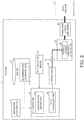
- Fig. 2 is a block diagram illustrating the configuration of the substantial part of the tractor 1. Note that, since normal functions of the tractor 1 as a tractor can be implemented using known technologies as described above, here, matters related to the present disclosure will be described.
- the tractor 1 includes a memory 10, an instruction accepting part 11, a lift controller 12 (oil-temperature acquiring part), an oil temperature sensor 13, the control valve 14 (supply valve), the hydraulic lifting device 15, and the three-point linkage mechanism 30.
- the memory 10 is a memory where data to be used by the tractor 1 is stored, and stores ascending flow rate characteristic data, descending flow rate characteristic data, an ascending restraint current value, and a descending restraint current value.
- One example of the ascending flow rate characteristic data is illustrated in 301 of Fig. 3A
- one example of the descending flow rate characteristic data is illustrated in 302 of Fig. 3B .
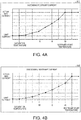
- one example of the ascending restraint current value is illustrated in 303 of Fig. 4A
- one example of the descending restraint current value is illustrated in 304 of Fig. 4B .
- FIG. 3A illustrates a current value given to the control valve 14 normally (ambient temperature) and an amount (flow rate) of oil which flows from the control valve 14 when the hydraulic lifting device 15 raises
- 302 (descending flow rate characteristic data) of Fig. 3B illustrates a current value given to the control valve 14 normally (ambient temperature) and an amount (flow rate) of oil which flows from the control valve 14 when the hydraulic lifting device 15 lowers (hereinafter, may be referred to as a "current/oil-amount characteristic").
- These examples are design data in which the oil begins to be supplied to the hydraulic lifting device 15 from the control valve 14 once an operation start current is given, and the flow rate which flows from the control valve 14 becomes the maximum at a designed maximum current.
- the current/oil-amount characteristic differs between raising and lowering of the hydraulic lifting device 15.
- the oil begins to be supplied at lower current when raising and it reaches the maximum flow rate at lower current when lowering, and the maximum flow rate is about 10% more when lowering.
- the maximum current actually given to the control valve 14 may be about 10% to 20% more than the designed current in consideration of manufacturing variation. In this embodiment, the actual maximum current is set as a value about 15% higher than the designed maximum current.
- 303 (ascending restraint current value) of Fig. 4A and 304 (descending restraint current value) of Fig. 4B associate the oil temperature with the restraint current value (hereinafter, may be referred to as a "temperature/restraint-maximum-current"), and are referred by a maximum-flow-rate setting part 21 (maximum oil amount setting part) which will be described later.
- the actual maximum current is set to a lower value under a low temperature (for example, 10°C or lower).
- the actual maximum current is restricted for both the raising and lowering of the hydraulic lifting device 15, and the lower current is given to the control valve 14.
- the actual maximum current is set lower as the temperature decreases.
- a fixed current (limit current) higher than the operation start current is used when the temperature is lower than a certain saturation temperature.
- the limit current is set as the limit current about 10% to 30% higher than the operation start current.
- the instruction accepting part 11 is an interface which accepts an instruction of a worker.
- the instruction accepting part 11 may be comprised of a touch panel, or may be comprised of a physical switch (a control lever, a push button, etc.).
- the instruction accepting part 11 accepts, from the worker, an instruction for raising the work machine 2, and notifies the instructed content to the lift controller 12.
- the lift controller 12 controls ascending and descending of the work machine 2 based on the content instructed from the worker through the instruction accepting part 11, and includes the maximum-flow-rate setting part 21 and a valve controlling part 22 (hydraulic drive controller). Note that the lift controller 12 may automatically read the content of work from the memory 10 and perform the control, in addition to when it accepts the instruction for raising the work machine 2 from the worker.
- the maximum-flow-rate setting part 21 acquires the oil temperature from the oil temperature sensor 13, and sets the current value corresponding to the acquired oil temperature as the maximum current value with reference to the ascending restraint current value 303.
- the maximum current value is not to give current exceeding this current value to the control valve 14, and corresponds to the maximum flow rate of the control valve 14. For example, referring to Fig. 4 , if the oil temperature is -10°C, the maximum current value is restricted to a value about 40% lower than the actual maximum current value, and the maximum flow rate of the control valve 14 becomes about 1/3 of the maximum flow rate.
- the maximum-flow-rate setting part 21 may use different maximum current values corresponding to the oil temperature, between raising and lowering the work machine 2. This is because the oil amount suitable for moving the work machine 2 changes due to the influence of the gravity etc. between the raising and lowering the work machine 2.
- the valve controlling part 22 transmits to the control valve 14 an instruction for raising and lowering the work machine 2 to a position corresponding to the ascending-and-descending instruction accepted by the instruction accepting part 11.
- the valve controlling part 22 controls the control valve 14 by giving to the control valve 14 current below the maximum current value set by the maximum-flow-rate setting part 21.
- the oil temperature sensor 13 detects a temperature of oil which flows near the control valve 14.
- the oil temperature sensor 13 is desirably disposed near the control valve 14, and, for example, it is disposed inside the hydraulic circuit of the lower links 32.
- the control valve 14 adjusts an amount of oil which flows into the hydraulic cylinder 16 by opening and closing the valve in response to an instruction from the valve controlling part 22.
- the detail of the hydraulic lifting device 15 is as described above.
- the three-point linkage mechanism 30 is provided with the single top link 31 and the left-and-right lower links 32 as described above, and it raises and lowers the work machine 2 while supporting it by three links.
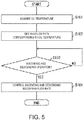
- FIG. 5 is a flowchart illustrating the flow of processing for ascending and descending the work machine 2.
- the maximum-flow-rate setting part 21 acquires the oil temperature detected by the oil temperature sensor 13, periodically or at a given timing (S101).
- the acquisition timing of the oil temperature may be a timing at which the instruction accepting part 11 accepts the ascending-and-descending instruction of the work machine 2 from the worker.
- the maximum-flow-rate setting part 21 sets the maximum current value corresponding to the oil temperature acquired at Step S101 with reference to the ascending restraint current value 303 (S102). Then, if the instruction accepting part 11 accepts the ascending-and-descending operation of the work machine 2 (YES at S103), the valve controlling part 22 raises and lowers the work machine 2 by controlling the control valve 14 with the current value below the maximum current value set at Step S102 (S104).
- the above is the flow of the processing when the tractor 1 raises and lowers the work machine 2.
- the tractor 1 restricts the maximum flow rate of the control valve 14 according to the oil temperature.
- the maximum flow rate is reduced as the oil temperature falls until it reaches the saturation temperature. Therefore, since the maximum flow rate of the control valve 14 falls under the low temperature, it can suppress the impairment in which when closing the control valve 14, the control valve 14 cannot be fully closed due to the viscosity of the oil.
- Embodiment 1 the problem due to the viscosity of the oil is solved by reducing the maximum flow rate of the control valve 14 under the low temperature.
- the maximum flow rate of the control valve 14 is reduced, since the amount of oil supplied to the hydraulic cylinder 16 decreases, the time required for raising and lowering the work machine 2 to the target position becomes longer than the case where the maximum flow rate is not reduced.
- a selection for giving priority to the accuracy of moving the work machine 2 to the target position (accuracy priority mode) or giving priority to the time required for moving the work machine 2 to the target position (time priority mode) is enabled.
- FIG. 6 is a flowchart illustrating the flow of the processing when the priority based on either the accuracy or the time is selectable.
- the maximum-flow-rate setting part 21 first acquires the oil temperature detected by the oil temperature sensor 13, periodically or at a given timing (S201). Next, the lift controller 12 determines whether it is in the "accuracy priority mode" (S202).
- the accuracy priority mode is a mode in which the priority is given to the accuracy of the target position to which the work machine 2 is moved rather than the time required for the movement, and it is set by the worker in advance.
- the maximum-flow-rate setting part 21 sets the maximum current value corresponding to the oil temperature acquired at Step S201 with reference to the ascending restraint current value 303 (S203). Then, if the instruction accepting part 11 accepts the ascending-and-descending operation of the work machine 2 (YES at S204), the valve controlling part 22 raises and lowers the work machine 2 by controlling the control valve 14 with the current value below the maximum current value set at Step S203 (S205).
- Step S202 if the lift controller 12 determines that it is not in the "accuracy priority mode" (NO at S202), it sets an allowable width corresponding to the oil temperature (S211).
- the allowable width is to indicate how much deviation from the target position is permissible. Note that, here, although the allowable width is set corresponding to the oil temperature, the allowable width may set as a constant without depending on the oil temperature.
- the valve controlling part 22 raises and lowers the work machine 2 by controlling the control valve 14 with the current value corresponding to a range of the normal flow rate (S213). Then, if the raised or lowered position of the work machine 2 is a position within the allowable width from the target position (YES at S214), the ascending-and-descending processing ends.
- the above is the flow of the processing for the tractor 1 raising and lowering the work machine 2 when the priority based on either the accuracy or the time can be selected.
- the determination of the allowable width is performed only when operating at the normal flow rate, it may determine whether the position falls within an allowable width similar to the right side Step S214 after the left side Step S205.
- the allowable width in the accuracy priority mode may be set narrower than the allowable width in the time priority mode so that the accuracy will not be dropped.
- the work machine 2 when the priority is given to the time, the work machine 2 can be moved near the target position at the fastest speed by providing the allowable width, while reducing the possibility of causing a so-called "hunting."
- the work machine 2 when the priority is given to the accuracy, the work machine 2 can be moved to the target position with sufficient accuracy, while reducing the possibility of causing the hunting, similar to Embodiment 1.
- the control block (particularly, the lift controller 12) of the tractor 1 may be implemented by a logic circuit (hardware) formed in an integrated circuit (IC chip) etc., or may be implemented by software.
- the tractor 1 is provided with a computer for executing a command of a program which is software for implementing each function.
- this computer is provided with at least one processor (control device), and is provided with at least one computer-readable recording medium which stores the program.
- the purpose of the present disclosure is achieved by the processor of the computer reading the program from the recording medium and executing the program.
- a CPU Central Processing Unit
- the recording medium a "non-transitory physical medium," such as a ROM (Read Only Memory), as well as a tape, a disc, a card, a semiconductor memory, and a programmable logic circuit, may be used.
- the program may further be provided with a RAM (Random Access Memory) which develops the program.
- the program may be supplied to the computer through an arbitrary transmission medium (a communication network, a broadcast wave, etc.) in which the program is transmittable.
- a transmission medium a communication network, a broadcast wave, etc.
- one aspect of the present disclosure may also be implemented in the form of a data signal embedded in a carrier wave, in which the program is embodied by an electronic transmission.
Landscapes
- Engineering & Computer Science (AREA)
- Life Sciences & Earth Sciences (AREA)
- Mechanical Engineering (AREA)
- Soil Sciences (AREA)
- Environmental Sciences (AREA)
- General Engineering & Computer Science (AREA)
- Physics & Mathematics (AREA)
- Fluid Mechanics (AREA)
- Civil Engineering (AREA)
- Mining & Mineral Resources (AREA)
- Structural Engineering (AREA)
- Chemical & Material Sciences (AREA)
- Analytical Chemistry (AREA)
- Zoology (AREA)
- Lifting Devices For Agricultural Implements (AREA)
- Fluid-Pressure Circuits (AREA)
- Vehicle Body Suspensions (AREA)
Applications Claiming Priority (1)
| Application Number | Priority Date | Filing Date | Title |
|---|---|---|---|
| JP2020030388A JP7216035B2 (ja) | 2020-02-26 | 2020-02-26 | 作業車両 |
Publications (3)
| Publication Number | Publication Date |
|---|---|
| EP3872269A2 true EP3872269A2 (de) | 2021-09-01 |
| EP3872269A3 EP3872269A3 (de) | 2021-09-08 |
| EP3872269B1 EP3872269B1 (de) | 2025-11-26 |
Family
ID=74758662
Family Applications (1)
| Application Number | Title | Priority Date | Filing Date |
|---|---|---|---|
| EP21159320.7A Active EP3872269B1 (de) | 2020-02-26 | 2021-02-25 | Nutzfahrzeug |
Country Status (3)
| Country | Link |
|---|---|
| US (1) | US11730074B2 (de) |
| EP (1) | EP3872269B1 (de) |
| JP (1) | JP7216035B2 (de) |
Families Citing this family (5)
| Publication number | Priority date | Publication date | Assignee | Title |
|---|---|---|---|---|
| JP7317757B2 (ja) * | 2020-03-24 | 2023-07-31 | 株式会社クボタ | 作業車両 |
| US12203243B2 (en) * | 2022-03-15 | 2025-01-21 | Caterpillar Inc. | Controlling an implement based on determining a target position of the implement |
| CN114688004B (zh) * | 2022-03-16 | 2023-10-27 | 三一重机有限公司 | 流量分配方法、装置及作业机械 |
| JP2024126390A (ja) * | 2023-03-07 | 2024-09-20 | 株式会社クボタ | 作業機及び作業機の制御方法 |
| JP2025149337A (ja) * | 2024-03-26 | 2025-10-08 | 株式会社クボタ | 作業機及び作業機の制御方法 |
Citations (2)
| Publication number | Priority date | Publication date | Assignee | Title |
|---|---|---|---|---|
| JP2010268755A (ja) | 2009-05-22 | 2010-12-02 | Mitsubishi Agricult Mach Co Ltd | 作業車輌の傾斜制御装置 |
| US9360005B2 (en) | 2013-01-24 | 2016-06-07 | Claas Saulgau Gmbh | Auxiliary device for an agricultural working machine |
Family Cites Families (6)
| Publication number | Priority date | Publication date | Assignee | Title |
|---|---|---|---|---|
| JPH076729Y2 (ja) * | 1987-11-12 | 1995-02-22 | セイレイ工業株式会社 | 対地作業機の昇降速度制御装置 |
| JP2001169620A (ja) * | 1999-12-17 | 2001-06-26 | Yanmar Agricult Equip Co Ltd | 田植機 |
| JP2006340621A (ja) * | 2005-06-07 | 2006-12-21 | Yanmar Co Ltd | 農作業機の耕耘制御装置 |
| JP4990333B2 (ja) | 2009-09-03 | 2012-08-01 | 株式会社小松製作所 | 作業車両 |
| US10451094B2 (en) * | 2015-09-28 | 2019-10-22 | Kubota Corporation | Hydraulic system of work machine |
| JP6618452B2 (ja) | 2016-11-09 | 2019-12-11 | 日立建機株式会社 | ハイブリッド建設機械 |
-
2020
- 2020-02-26 JP JP2020030388A patent/JP7216035B2/ja active Active
-
2021
- 2021-02-11 US US17/173,227 patent/US11730074B2/en active Active
- 2021-02-25 EP EP21159320.7A patent/EP3872269B1/de active Active
Patent Citations (2)
| Publication number | Priority date | Publication date | Assignee | Title |
|---|---|---|---|---|
| JP2010268755A (ja) | 2009-05-22 | 2010-12-02 | Mitsubishi Agricult Mach Co Ltd | 作業車輌の傾斜制御装置 |
| US9360005B2 (en) | 2013-01-24 | 2016-06-07 | Claas Saulgau Gmbh | Auxiliary device for an agricultural working machine |
Also Published As
| Publication number | Publication date |
|---|---|
| US20210259147A1 (en) | 2021-08-26 |
| JP7216035B2 (ja) | 2023-01-31 |
| US11730074B2 (en) | 2023-08-22 |
| EP3872269B1 (de) | 2025-11-26 |
| EP3872269A3 (de) | 2021-09-08 |
| JP2021132560A (ja) | 2021-09-13 |
Similar Documents
| Publication | Publication Date | Title |
|---|---|---|
| EP3872269B1 (de) | Nutzfahrzeug | |
| CA2492414C (en) | Control system for a load handling apparatus | |
| KR950005391B1 (ko) | 농작업기의 승강제어장치 | |
| JP7317757B2 (ja) | 作業車両 | |
| JPS6344804A (ja) | 対地作業機のミツクスコントロ−ル装置 | |
| JPH0779606A (ja) | 対地作業装置のローリング制御機構 | |
| JPH0711526Y2 (ja) | 農用トラクタのドラフト制御装置 | |
| JP3372465B2 (ja) | 農作業機の作業装置用昇降制御装置 | |
| JP2600123B2 (ja) | トラクターの油圧昇降制御装置 | |
| KR900003034B1 (ko) | 대지작업장치를 고속과 저속으로 승강제어하는 경작심도 제어장치 | |
| JPH07163206A (ja) | トラクタ−の油圧制御装置 | |
| JP2781316B2 (ja) | 耕耘装置の昇降制御装置 | |
| JP2574432B2 (ja) | 異動農機の油圧昇降制御装置 | |
| JPH0787724B2 (ja) | トラクタの作業機昇降制御装置 | |
| JP2510037B2 (ja) | 昇降制御装置 | |
| JPH0720403B2 (ja) | 対地作業の油圧制御装置 | |
| JPH03247201A (ja) | ロータリ耕耘装置の後退上昇制御装置 | |
| JPS6244106A (ja) | トラクタの昇降制御装置 | |
| JP3003334B2 (ja) | トラクタの作業機昇降制御装置 | |
| JPH06339302A (ja) | トラクタ−の油圧昇降制御装置 | |
| JPS6087706A (ja) | 農作業機の昇降制御装置 | |
| JPS63160504A (ja) | 昇降制御装置 | |
| JPH10136710A (ja) | トラクタの負荷制御装置 | |
| JPS63279704A (ja) | トラクタの作業機昇降制御装置 | |
| JPH0779608A (ja) | 耕耘装置の昇降制御装置 |
Legal Events
| Date | Code | Title | Description |
|---|---|---|---|
| PUAI | Public reference made under article 153(3) epc to a published international application that has entered the european phase |
Free format text: ORIGINAL CODE: 0009012 |
|
| STAA | Information on the status of an ep patent application or granted ep patent |
Free format text: STATUS: REQUEST FOR EXAMINATION WAS MADE |
|
| PUAL | Search report despatched |
Free format text: ORIGINAL CODE: 0009013 |
|
| 17P | Request for examination filed |
Effective date: 20210225 |
|
| AK | Designated contracting states |
Kind code of ref document: A2 Designated state(s): AL AT BE BG CH CY CZ DE DK EE ES FI FR GB GR HR HU IE IS IT LI LT LU LV MC MK MT NL NO PL PT RO RS SE SI SK SM TR |
|
| AK | Designated contracting states |
Kind code of ref document: A3 Designated state(s): AL AT BE BG CH CY CZ DE DK EE ES FI FR GB GR HR HU IE IS IT LI LT LU LV MC MK MT NL NO PL PT RO RS SE SI SK SM TR |
|
| RIC1 | Information provided on ipc code assigned before grant |
Ipc: F16H 61/4165 20100101ALI20210802BHEP Ipc: E02F 9/26 20060101ALI20210802BHEP Ipc: A01D 69/03 20060101ALI20210802BHEP Ipc: A01B 63/10 20060101ALI20210802BHEP Ipc: E02F 9/22 20060101AFI20210802BHEP |
|
| STAA | Information on the status of an ep patent application or granted ep patent |
Free format text: STATUS: EXAMINATION IS IN PROGRESS |
|
| 17Q | First examination report despatched |
Effective date: 20241212 |
|
| GRAP | Despatch of communication of intention to grant a patent |
Free format text: ORIGINAL CODE: EPIDOSNIGR1 |
|
| STAA | Information on the status of an ep patent application or granted ep patent |
Free format text: STATUS: GRANT OF PATENT IS INTENDED |
|
| RIC1 | Information provided on ipc code assigned before grant |
Ipc: E02F 9/22 20060101AFI20250611BHEP Ipc: F16H 61/4165 20100101ALI20250611BHEP Ipc: E02F 9/26 20060101ALI20250611BHEP Ipc: A01D 69/03 20060101ALI20250611BHEP Ipc: A01B 63/10 20060101ALI20250611BHEP Ipc: F15B 21/045 20190101ALI20250611BHEP Ipc: F15B 21/08 20060101ALI20250611BHEP Ipc: F16H 59/72 20060101ALI20250611BHEP |
|
| INTG | Intention to grant announced |
Effective date: 20250620 |
|
| GRAS | Grant fee paid |
Free format text: ORIGINAL CODE: EPIDOSNIGR3 |
|
| GRAA | (expected) grant |
Free format text: ORIGINAL CODE: 0009210 |
|
| STAA | Information on the status of an ep patent application or granted ep patent |
Free format text: STATUS: THE PATENT HAS BEEN GRANTED |
|
| AK | Designated contracting states |
Kind code of ref document: B1 Designated state(s): AL AT BE BG CH CY CZ DE DK EE ES FI FR GB GR HR HU IE IS IT LI LT LU LV MC MK MT NL NO PL PT RO RS SE SI SK SM TR |
|
| REG | Reference to a national code |
Ref country code: CH Ref legal event code: F10 Free format text: ST27 STATUS EVENT CODE: U-0-0-F10-F00 (AS PROVIDED BY THE NATIONAL OFFICE) Effective date: 20251126 Ref country code: GB Ref legal event code: FG4D |
|
| REG | Reference to a national code |
Ref country code: IE Ref legal event code: FG4D |
|
| REG | Reference to a national code |
Ref country code: DE Ref legal event code: R096 Ref document number: 602021042903 Country of ref document: DE |
|
| PG25 | Lapsed in a contracting state [announced via postgrant information from national office to epo] |
Ref country code: ES Free format text: LAPSE BECAUSE OF FAILURE TO SUBMIT A TRANSLATION OF THE DESCRIPTION OR TO PAY THE FEE WITHIN THE PRESCRIBED TIME-LIMIT Effective date: 20251126 |
|
| REG | Reference to a national code |
Ref country code: LT Ref legal event code: MG9D |
|
| PG25 | Lapsed in a contracting state [announced via postgrant information from national office to epo] |
Ref country code: NO Free format text: LAPSE BECAUSE OF FAILURE TO SUBMIT A TRANSLATION OF THE DESCRIPTION OR TO PAY THE FEE WITHIN THE PRESCRIBED TIME-LIMIT Effective date: 20260226 |
|
| PGFP | Annual fee paid to national office [announced via postgrant information from national office to epo] |
Ref country code: DE Payment date: 20260313 Year of fee payment: 6 |
|
| PG25 | Lapsed in a contracting state [announced via postgrant information from national office to epo] |
Ref country code: HR Free format text: LAPSE BECAUSE OF FAILURE TO SUBMIT A TRANSLATION OF THE DESCRIPTION OR TO PAY THE FEE WITHIN THE PRESCRIBED TIME-LIMIT Effective date: 20251126 Ref country code: FI Free format text: LAPSE BECAUSE OF FAILURE TO SUBMIT A TRANSLATION OF THE DESCRIPTION OR TO PAY THE FEE WITHIN THE PRESCRIBED TIME-LIMIT Effective date: 20251126 Ref country code: AT Free format text: LAPSE BECAUSE OF FAILURE TO SUBMIT A TRANSLATION OF THE DESCRIPTION OR TO PAY THE FEE WITHIN THE PRESCRIBED TIME-LIMIT Effective date: 20251126 |
|
| REG | Reference to a national code |
Ref country code: AT Ref legal event code: MK05 Ref document number: 1861171 Country of ref document: AT Kind code of ref document: T Effective date: 20251126 |
|
| PG25 | Lapsed in a contracting state [announced via postgrant information from national office to epo] |
Ref country code: NL Free format text: LAPSE BECAUSE OF FAILURE TO SUBMIT A TRANSLATION OF THE DESCRIPTION OR TO PAY THE FEE WITHIN THE PRESCRIBED TIME-LIMIT Effective date: 20251126 |
|
| PG25 | Lapsed in a contracting state [announced via postgrant information from national office to epo] |
Ref country code: RS Free format text: LAPSE BECAUSE OF FAILURE TO SUBMIT A TRANSLATION OF THE DESCRIPTION OR TO PAY THE FEE WITHIN THE PRESCRIBED TIME-LIMIT Effective date: 20260226 |
|
| PG25 | Lapsed in a contracting state [announced via postgrant information from national office to epo] |
Ref country code: IS Free format text: LAPSE BECAUSE OF FAILURE TO SUBMIT A TRANSLATION OF THE DESCRIPTION OR TO PAY THE FEE WITHIN THE PRESCRIBED TIME-LIMIT Effective date: 20260326 |
|
| PGFP | Annual fee paid to national office [announced via postgrant information from national office to epo] |
Ref country code: FR Payment date: 20260219 Year of fee payment: 6 |
|
| PG25 | Lapsed in a contracting state [announced via postgrant information from national office to epo] |
Ref country code: PT Free format text: LAPSE BECAUSE OF FAILURE TO SUBMIT A TRANSLATION OF THE DESCRIPTION OR TO PAY THE FEE WITHIN THE PRESCRIBED TIME-LIMIT Effective date: 20260326 |
|
| PG25 | Lapsed in a contracting state [announced via postgrant information from national office to epo] |
Ref country code: PL Free format text: LAPSE BECAUSE OF FAILURE TO SUBMIT A TRANSLATION OF THE DESCRIPTION OR TO PAY THE FEE WITHIN THE PRESCRIBED TIME-LIMIT Effective date: 20251126 |
|
| PG25 | Lapsed in a contracting state [announced via postgrant information from national office to epo] |
Ref country code: LV Free format text: LAPSE BECAUSE OF FAILURE TO SUBMIT A TRANSLATION OF THE DESCRIPTION OR TO PAY THE FEE WITHIN THE PRESCRIBED TIME-LIMIT Effective date: 20251126 |
|
| PG25 | Lapsed in a contracting state [announced via postgrant information from national office to epo] |
Ref country code: BG Free format text: LAPSE BECAUSE OF FAILURE TO SUBMIT A TRANSLATION OF THE DESCRIPTION OR TO PAY THE FEE WITHIN THE PRESCRIBED TIME-LIMIT Effective date: 20251126 |