EP3871777A1 - Device for treating a mixture of materials consisting of substitute fuel and impurity - Google Patents
Device for treating a mixture of materials consisting of substitute fuel and impurity Download PDFInfo
- Publication number
- EP3871777A1 EP3871777A1 EP20159298.7A EP20159298A EP3871777A1 EP 3871777 A1 EP3871777 A1 EP 3871777A1 EP 20159298 A EP20159298 A EP 20159298A EP 3871777 A1 EP3871777 A1 EP 3871777A1
- Authority
- EP
- European Patent Office
- Prior art keywords
- rotor mill
- material mixture
- tools
- feed
- separating device
- Prior art date
- Legal status (The legal status is an assumption and is not a legal conclusion. Google has not performed a legal analysis and makes no representation as to the accuracy of the status listed.)
- Pending
Links
Images

Classifications
-
- B—PERFORMING OPERATIONS; TRANSPORTING
- B02—CRUSHING, PULVERISING, OR DISINTEGRATING; PREPARATORY TREATMENT OF GRAIN FOR MILLING
- B02C—CRUSHING, PULVERISING, OR DISINTEGRATING IN GENERAL; MILLING GRAIN
- B02C23/00—Auxiliary methods or auxiliary devices or accessories specially adapted for crushing or disintegrating not provided for in preceding groups or not specially adapted to apparatus covered by a single preceding group
- B02C23/18—Adding fluid, other than for crushing or disintegrating by fluid energy
- B02C23/24—Passing gas through crushing or disintegrating zone
- B02C23/30—Passing gas through crushing or disintegrating zone the applied gas acting to effect material separation
-
- B—PERFORMING OPERATIONS; TRANSPORTING
- B02—CRUSHING, PULVERISING, OR DISINTEGRATING; PREPARATORY TREATMENT OF GRAIN FOR MILLING
- B02C—CRUSHING, PULVERISING, OR DISINTEGRATING IN GENERAL; MILLING GRAIN
- B02C13/00—Disintegrating by mills having rotary beater elements ; Hammer mills
- B02C13/14—Disintegrating by mills having rotary beater elements ; Hammer mills with vertical rotor shaft, e.g. combined with sifting devices
- B02C13/16—Disintegrating by mills having rotary beater elements ; Hammer mills with vertical rotor shaft, e.g. combined with sifting devices with beaters hinged to the rotor
-
- B—PERFORMING OPERATIONS; TRANSPORTING
- B02—CRUSHING, PULVERISING, OR DISINTEGRATING; PREPARATORY TREATMENT OF GRAIN FOR MILLING
- B02C—CRUSHING, PULVERISING, OR DISINTEGRATING IN GENERAL; MILLING GRAIN
- B02C13/00—Disintegrating by mills having rotary beater elements ; Hammer mills
- B02C13/14—Disintegrating by mills having rotary beater elements ; Hammer mills with vertical rotor shaft, e.g. combined with sifting devices
- B02C13/18—Disintegrating by mills having rotary beater elements ; Hammer mills with vertical rotor shaft, e.g. combined with sifting devices with beaters rigidly connected to the rotor
-
- B—PERFORMING OPERATIONS; TRANSPORTING
- B02—CRUSHING, PULVERISING, OR DISINTEGRATING; PREPARATORY TREATMENT OF GRAIN FOR MILLING
- B02C—CRUSHING, PULVERISING, OR DISINTEGRATING IN GENERAL; MILLING GRAIN
- B02C13/00—Disintegrating by mills having rotary beater elements ; Hammer mills
- B02C13/26—Details
- B02C13/282—Shape or inner surface of mill-housings
- B02C13/284—Built-in screens
-
- B—PERFORMING OPERATIONS; TRANSPORTING
- B02—CRUSHING, PULVERISING, OR DISINTEGRATING; PREPARATORY TREATMENT OF GRAIN FOR MILLING
- B02C—CRUSHING, PULVERISING, OR DISINTEGRATING IN GENERAL; MILLING GRAIN
- B02C23/00—Auxiliary methods or auxiliary devices or accessories specially adapted for crushing or disintegrating not provided for in preceding groups or not specially adapted to apparatus covered by a single preceding group
- B02C23/02—Feeding devices
-
- B—PERFORMING OPERATIONS; TRANSPORTING
- B02—CRUSHING, PULVERISING, OR DISINTEGRATING; PREPARATORY TREATMENT OF GRAIN FOR MILLING
- B02C—CRUSHING, PULVERISING, OR DISINTEGRATING IN GENERAL; MILLING GRAIN
- B02C23/00—Auxiliary methods or auxiliary devices or accessories specially adapted for crushing or disintegrating not provided for in preceding groups or not specially adapted to apparatus covered by a single preceding group
- B02C23/08—Separating or sorting of material, associated with crushing or disintegrating
- B02C23/16—Separating or sorting of material, associated with crushing or disintegrating with separator defining termination of crushing or disintegrating zone, e.g. screen denying egress of oversize material
-
- B—PERFORMING OPERATIONS; TRANSPORTING
- B02—CRUSHING, PULVERISING, OR DISINTEGRATING; PREPARATORY TREATMENT OF GRAIN FOR MILLING
- B02C—CRUSHING, PULVERISING, OR DISINTEGRATING IN GENERAL; MILLING GRAIN
- B02C23/00—Auxiliary methods or auxiliary devices or accessories specially adapted for crushing or disintegrating not provided for in preceding groups or not specially adapted to apparatus covered by a single preceding group
- B02C23/18—Adding fluid, other than for crushing or disintegrating by fluid energy
-
- B—PERFORMING OPERATIONS; TRANSPORTING
- B02—CRUSHING, PULVERISING, OR DISINTEGRATING; PREPARATORY TREATMENT OF GRAIN FOR MILLING
- B02C—CRUSHING, PULVERISING, OR DISINTEGRATING IN GENERAL; MILLING GRAIN
- B02C13/00—Disintegrating by mills having rotary beater elements ; Hammer mills
- B02C13/26—Details
- B02C13/288—Ventilating, or influencing air circulation
-
- B—PERFORMING OPERATIONS; TRANSPORTING
- B02—CRUSHING, PULVERISING, OR DISINTEGRATING; PREPARATORY TREATMENT OF GRAIN FOR MILLING
- B02C—CRUSHING, PULVERISING, OR DISINTEGRATING IN GENERAL; MILLING GRAIN
- B02C13/00—Disintegrating by mills having rotary beater elements ; Hammer mills
- B02C13/26—Details
- B02C13/28—Shape or construction of beater elements
- B02C2013/2812—Shape or construction of beater elements the beater elements are attached to a hollow cylindrical rotor
-
- B—PERFORMING OPERATIONS; TRANSPORTING
- B02—CRUSHING, PULVERISING, OR DISINTEGRATING; PREPARATORY TREATMENT OF GRAIN FOR MILLING
- B02C—CRUSHING, PULVERISING, OR DISINTEGRATING IN GENERAL; MILLING GRAIN
- B02C23/00—Auxiliary methods or auxiliary devices or accessories specially adapted for crushing or disintegrating not provided for in preceding groups or not specially adapted to apparatus covered by a single preceding group
- B02C23/08—Separating or sorting of material, associated with crushing or disintegrating
- B02C23/16—Separating or sorting of material, associated with crushing or disintegrating with separator defining termination of crushing or disintegrating zone, e.g. screen denying egress of oversize material
- B02C2023/165—Screen denying egress of oversize material
-
- B—PERFORMING OPERATIONS; TRANSPORTING
- B02—CRUSHING, PULVERISING, OR DISINTEGRATING; PREPARATORY TREATMENT OF GRAIN FOR MILLING
- B02C—CRUSHING, PULVERISING, OR DISINTEGRATING IN GENERAL; MILLING GRAIN
- B02C2201/00—Codes relating to disintegrating devices adapted for specific materials
- B02C2201/06—Codes relating to disintegrating devices adapted for specific materials for garbage, waste or sewage
Definitions
- the present invention relates to a method for processing a material mixture consisting of substitute fuel and impurities, which is sifted, comminuted and dried in the device.
- the substitute fuel also known as secondary fuel, includes in particular solid waste, which can be used together with conventional fuels, especially in cement, lime, lignite or industrial power plants as well as in waste incineration plants or as the sole fuel in substitute fuel power plants.
- the solid waste for example, consisting of commercial waste and / or household waste, generally still contains contaminants such as glass or metals after being roughly shredded. It is therefore known to carry out a separation after the coarse comminution and, if necessary, to comminute the substitute fuel further.
- the object of the present invention is therefore to provide a device with which both the impurities can be separated from the substitute fuel and the substitute fuel can be generated with a different mean size of the substitute fuel particles.
- the object is achieved by a device for processing a material mixture consisting of substitute fuel and impurities, having a vertically oriented central feed, a separating device arranged below the central feed, a rotor mill, the rotor mill being arranged above the separating device and surrounding the central feed, and a flow device for generating an upwardly directed gas flow, wherein the material mixture can be introduced into the feed and sinks after the introduction into the feed to the separating device, wherein the contaminant in the separating device is at least partially separated as a contaminant fraction from the material mixture and that of the separated material mixture rises with the gas flow to the rotor mill, the rising material mixture being comminuted in the rotor mill.
- the rotor mill has a plurality of tools arranged vertically and offset from one another in the circumferential direction.
- the material mixture can, for example, be introduced into the feed via a funnel or another feeding device, the feed being aligned vertically so that the material mixture introduced into the feed sinks in the feed.
- the feed is hollow on the inside so that the material mixture can sink undisturbed.
- the feed can be formed by a tube (hollow cylinder).
- a separating device is arranged below the central feed, which includes, for example, a rotatably drivable spreading plate.
- the separating device is designed in particular so that at least a large proportion of the Contaminants from the material mixture can be separated (sifted), wherein the separated contaminants can be removed from the device in a suitable manner.
- a flow device for separation / sifting, by means of which an upwardly rising gas flow can be generated at least in the area of the separation device, in particular in the area of the spreading plate of the separation device, and the rotor mill.
- the flow device has in particular at least one gas inlet preferably arranged in the lower region of the device and at least one outlet in the upper region of the rotor mill.
- heated air can be used as the gas.
- the material mixture supplied through the central feed is thrown from the spreading plate into a space surrounding the spreading plate, in which the gas flow rises, with the rising gas flow only taking the substitute fuel with it, if possible, and a large part of the impurities in the spreading plate surrounding space drops.
- the substitute fuel that has been taken along is then also dried with the gas flow.
- the substitute fuel carried along by the gas flow (and any impurities that have not been separated off) is fed with the gas flow to the rotor mill, which is arranged above the separating device (spreading plate).
- the substitute fuel is crushed in the rotor mill by impact, shear and impact forces.
- the rotor mill preferably has at least one rotationally driven tool which promotes the comminution of the substitute fuel.
- the separating device (and in particular its spreading plate) and the tools of the rotor mill can preferably be driven together to rotate (rotationally) about a vertically aligned axis.
- the feed can also be driven to rotate at the same time.
- the spreading plate can be non-rotatably connected to the element delimiting the feed (for example a pipe), the at least one tool of the rotor mill preferably being attached to an outside of the element forming the central feed inside.
- only one drive has to be provided for generating the rotary movement.
- the drive is arranged in particular in the lower region of the device and can, for example, generate a rotary movement with 500 to 1000, preferably with 700 to 900 revolutions / min.
- the invention also provides that the rotor mill (and in particular also each stage of the rotor mill) has a plurality of, in particular more than 10, preferably more than 20 tools arranged vertically and offset from one another in the circumferential direction.
- This arrangement of the tools, offset both in the circumferential direction and in the vertical direction, results in a longer dwell time of the material mixture and thus more effective comminution of the material mixture, so that a higher degree of comminution can be achieved or the rotor mill can be realized with a lower height.
- the longer dwell time also improves the drying of the material mixture.
- the rotor mill has a centrally arranged and rotationally driven hollow cylinder (which preferably also forms the central feed), on the outside of which the tools are attached, the tools each extending individually radially outward from the outside of the hollow cylinder .
- the tools are in particular elongated elements that differ from the Hollow cylinder extend outward.
- a group of tools and / or most tools include flat wing elements that extend radially outward.
- the wing elements are attached directly or indirectly to the outside of the hollow cylinder and are considerably longer in the radial direction (at least three times, preferably at least five times) as long as their width.
- the wing elements have a height which is less than their width, the wing elements being at least twice, preferably four times as wide as they are high. It has been found that a particularly efficient comminution of the material mixture is possible with such wing-like elements.
- a further improvement in the comminution can be achieved in that the wing elements are positioned at an angle to a horizontal plane.
- the setting angle is preferably 3 ° to 45 °, particularly preferably 5 ° to 20 °, to the horizontal plane.
- At least one tool or a plurality of tools comprises a plate-shaped impact element which is arranged at a radial end of the tool, the plate-shaped impact element being particularly vertically aligned.
- the plate-shaped impact element With such a plate-shaped impact element, the comminution efficiency can be further increased.
- At least one tool comprises a scraping element which is arranged radially on the outside of the tool and is in contact with a wall of the rotor mill or the stage of the rotor mill that delimits the grinding chamber on the outside, the wall being formed, for example, by a grid arrangement can that separates the grinding chamber from an annulus.
- a scraping element which is arranged radially on the outside of the tool and is in contact with a wall of the rotor mill or the stage of the rotor mill that delimits the grinding chamber on the outside, the wall being formed, for example, by a grid arrangement can that separates the grinding chamber from an annulus.
- the plate-shaped impact element or the scraping element can, for example, be attached to a radial end of the previously described wing element of the tool.
- At least one tool is formed from a wire which is attached to the outside of the hollow cylinder.
- a wire is understood in particular to be such an element which extends outwardly from the hollow cylinder and whose width and height are approximately the same.
- the wire preferably has a circular cross-sectional configuration.
- a plurality (in particular more than 8, preferably more than 16) of tools are preferably arranged in a lower area of the rotor mill or in a lower area of a stage of the rotor mill, each of which comprises a vane element, while in an upper area of the rotor mill or in one
- a plurality of tools comprising a wire are arranged in the upper region of a stage of the rotor mill.
- a group (more than 4) of tools can be arranged helically offset from one another (i.e. on a helical line), whereby several groups of tools can be arranged one behind the other in the circumferential direction.
- the rotor mill is multi-stage, i.e. has at least and preferably exactly two or three stages, optionally four stages, with at least one separating device (for example a sieve) being arranged between the stages of the rotor mill
- Separation device not retained material mixture is further comminuted in the following stage, in particular particles of the mainly substitute fuel containing material mixture with a particle size specified by the separation device are retained in the previous stage, while particles of the material mixture with a smaller size can get into the following stage .
- the material mixture is then comminuted further.
- the multi-stage rotor mill means that one device can provide substitute fuel with different mean particle sizes.
- the fraction of the material mixture withdrawn from the first stage can, for example, have an average particle size between 60 and 200 mm, while the fraction of the material mixture withdrawn from the second stage can have an average particle size of, for example, 10 to 60 mm.
- At least one outlet is assigned to each stage of the rotor mill, via which the correspondingly comminuted material mixture, which mainly or at best exclusively contains substitute fuel, can be drawn off.
- the second and, if appropriate, any further stage of the rotor mill are arranged in particular vertically above the first or preceding stage, the tools of each stage preferably being driven by a single common drive.
- the separating device comprises at least one sieve in each case between the stages of the rotor mill.
- a simple separating device is provided with such a sieve.
- annular space is formed which surrounds the first stage of the rotor mill, in particular a grid arrangement functioning as a sieve being arranged between the outer annular space and the tools of the first stage of the rotor mill.
- the material mixture comminuted in the first stage of the rotor mill can thus pass through the grid arrangement into the annular space, from which the comminuted material mixture can be withdrawn through the at least one first outlet. If a plurality (more than two) stages are formed, each stage following the first stage up to the last stage can also be assigned its own annular space which is separated from the tools of the corresponding stage by a grid arrangement.
- the separating device is assigned a cleaning device between the stages of the rotor mill, with which the material mixture retained by the separating device can be released from the separating device.
- the dissolved material mixture can thus be fed to a further comminution in the preceding stage, for which purpose, for example, a pulsation of the gas flow is also possible.
- the cleaning device can also be rotatably driven together with the tools of the previous stage, so that a continuous release of the retained material mixture from the separating device is possible.
- the device shown in the figures for processing a material mixture consisting of substitute fuel and impurities has a vertically oriented central feed 1 which is radially delimited by a hollow cylinder 12.
- a funnel is formed above the feed 1 through which the material mixture is fed into the feed 1.
- a separating device 2 which comprises a spreading plate 14, is formed below the central feed 1.
- the spreading plate 14 is non-rotatably connected to the hollow cylinder 12, so that the spreading plate 14 and the hollow cylinder 12 can be driven to rotate together.
- Tools in the form of wing elements 8a and wires 8b are arranged on the outside of the hollow cylinder 12, so that they can be driven to rotate together with the hollow cylinder 12 about the longitudinal axis of the hollow cylinder.
- the tools 8a, 8b form a rotor mill 3 arranged above the separating device 2.
- the device also comprises a flow device 4 with an inlet 15, a first outlet 7.1 and a second outlet 7.2.
- the flow device 4 can be operated by blowing in a gaseous operating medium at the inlet 15 or by sucking off the gaseous operating medium at the outlets 7.1 and 7.2.
- the interior of the device is designed in such a way that the operating medium entering through the inlet 15 flows upwards past the radially outer edge of the spreading plate 14 into the rotor mill 3.
- the rotor mill 3 has a first stage 5.1 to which the first outlet 7.1 is assigned.
- the rotor mill 3 also has a second stage 5.2, to which the second outlet 7.2 is assigned.
- the tools 8a and 8b of the first stage 5.1 are radially surrounded by a grid arrangement 10 which separates the tools from an annular space 9.
- a separating device 6 in the form of a sieve is formed between the first stage 5.1 and the second stage 5.2.
- the first stage 5.1 and the second stage 5.2 of the rotor mill 3 each comprise a multiplicity of vane elements 8a which are attached in groups in a helical manner to the outside of the hollow cylinder 12 and which extend from the outside of the hollow cylinder extend radially outward.
- the wing elements 8a are aligned with an angle of attack to a horizontal plane.
- Plate-shaped impact elements 13 are attached to the outer ends of the wing elements 8a.
- scraping elements 11 are attached to some wing elements 8a, with which components of the material mixture retained by the grid arrangement 10 can be detached from the grid arrangement 10.
- scratching elements can also be attached indirectly to the hollow cylinder 12 as a cleaning device, with which material retained by the separating device 6 can be detached.
- the first stage 5.1 and the second stage 5.2 each have wires 8b as tools, which are attached to the outside of the hollow cylinder 12.
- a material mixture consisting of substitute fuel and impurities is introduced into the vertically oriented central feed 1, in which the material mixture sinks down to the separating device 2 comprising the spreading plate 14.
- the material mixture is accelerated radially outwards when it reaches the spreading plate 14 at the latest.
- the material mixture passing over the outer radial edge of the spreading plate 14 is sifted due to the rising gas flow, so that above all foreign matter in the space surrounding the spreading plate 14 sinks down, while the remaining material mixture, mainly containing substitute fuel, with the gas flow into the first stage 5.1 of the rotor mill 3 entry.
- the material mixture is comminuted by interacting with the tools 8a and 8b as well as with each other. Due to the vertically and circumferentially offset arrangement of the tools 8a, 8b, effective comminution can take place, with comminuted Material can pass through the grid arrangement 10 into the annular space 9, this part of the material mixture being withdrawn from the first outlet 7.1.
- the material mixture passing through the separating device 6 is further comminuted in the second stage 5.2, so that the material mixture exiting from the second outlet 7.2 has a smaller mean particle size than the material mixture exiting from the first outlet 7.1.
- the device can therefore not only be used for particularly efficient comminution, but rather a material mixture with different particle sizes can also be provided.
Abstract
Die vorliegende Erfindung betrifft eine Vorrichtung zum Aufbereiten eines aus Ersatzbrennstoff und Störstoff bestehenden Materialgemischs, aufweisend eine vertikal ausgerichtete zentrale Zuführung (1), eine unterhalb der zentralen Zuführung (1) angeordnete Trenneinrichtung (2), eine Rotormühle (3), wobei die Rotormühle (3) oberhalb der Trenneinrichtung (2) angeordnet ist und die zentrale Zuführung (1) umgibt, eine Strömungseinrichtung (4) zur Erzeugung eines nach oben gerichteten Gasstroms, wobei die Rotormühle (3) mehrere vertikal und in Umfangsrichtung versetzt zueinander angeordnete Werkzeuge (8a, 8b) aufweist.The present invention relates to a device for processing a material mixture consisting of substitute fuel and impurities, having a vertically oriented central feed (1), a separating device (2) arranged below the central feed (1), a rotor mill (3), the rotor mill ( 3) is arranged above the separating device (2) and surrounds the central feed (1), a flow device (4) for generating an upwardly directed gas flow, the rotor mill (3) having several tools (8a, 8a, 8b).
Description
Die vorliegende Erfindung betrifft ein Verfahren zum Aufbereiten eines aus Ersatzbrennstoff und Störstoff bestehenden Materialgemischs, welches in der Vorrichtung gesichtet, zerkleinert und getrocknet wird.The present invention relates to a method for processing a material mixture consisting of substitute fuel and impurities, which is sifted, comminuted and dried in the device.
Der auch als Sekundärbrennstoff bezeichnete Ersatzbrennstoff umfasst insbesondere feste Abfälle, welche zusammen mit konventionellen Brennstoffen vor allem in Zement-, Kalk-, Braunkohle- oder Industriekraftwerken sowie in Müllverbrennungsanlagen oder als alleiniger Brennstoff in Ersatzbrennstoff-Kraftwerken eingesetzt werden kann. Der beispielsweise aus Gewerbeabfällen und/oder Hausmüll bestehende feste Abfall weist in der Regel nach einer Grobzerkleinerung noch Störstoffe, wie Glas oder Metalle, auf. Es ist daher bekannt, nach der Grobzerkleinerung eine Separierung vorzunehmen und den Ersatzbrennstoff gegebenenfalls weiter zu zerkleinern.The substitute fuel, also known as secondary fuel, includes in particular solid waste, which can be used together with conventional fuels, especially in cement, lime, lignite or industrial power plants as well as in waste incineration plants or as the sole fuel in substitute fuel power plants. The solid waste, for example, consisting of commercial waste and / or household waste, generally still contains contaminants such as glass or metals after being roughly shredded. It is therefore known to carry out a separation after the coarse comminution and, if necessary, to comminute the substitute fuel further.
Aufgabe der vorliegenden Erfindung ist es daher, eine Vorrichtung anzugeben, mit der sowohl eine Separierung der Störstoffe vom Ersatzbrennstoff möglich ist als auch der Ersatzbrennstoff mit einer unterschiedlichen mittleren Größe der Ersatzbrennstoffpartikel erzeugt werden kann.The object of the present invention is therefore to provide a device with which both the impurities can be separated from the substitute fuel and the substitute fuel can be generated with a different mean size of the substitute fuel particles.
Die Aufgabe wird gelöst durch eine Vorrichtung mit den Merkmalen des unabhängigen Anspruchs. Vorteilhafte Weiterbildungen der Vorrichtung sind in den abhängigen Ansprüchen und in der Beschreibung angegeben, wobei einzelne Merkmale der vorteilhaften Weiterbildungen in technisch sinnvoller Weise miteinander kombinierbar sind.The object is achieved by a device with the features of the independent claim. Advantageous developments of the device are in the dependent claims and specified in the description, with individual features of the advantageous developments being able to be combined with one another in a technically meaningful manner.
Gelöst wird die Aufgabe durch eine Vorrichtung zum Aufbereiten eines aus Ersatzbrennstoff und Störstoff bestehenden Materialgemischs, aufweisend eine vertikal ausgerichtete zentrale Zuführung, eine unterhalb der zentralen Zuführung angeordnete Trenneinrichtung, eine Rotormühle, wobei die Rotormühle oberhalb der Trenneinrichtung angeordnet ist und die zentrale Zuführung umgibt, und eine Strömungseinrichtung zur Erzeugung eines nach oben gerichteten Gasstroms, wobei das Materialgemisch in die Zuführung einführbar ist und nach der Einführung in die Zuführung zu der Trenneinrichtung absinkt, wobei der Störstoff in der Trenneinrichtung zumindest teilweise als eine Störstofffraktion aus dem Materialgemisch abgeschieden wird und das von den abgeschiedenen Störstoffen getrennte Materialgemisch mit dem Gasstrom zu der Rotormühle aufsteigt, wobei das aufsteigende Materialgemisch in der Rotormühle zerkleinert wird. Es ist zudem vorgesehen, dass die Rotormühle mehrere vertikal und in Umfangsrichtung versetzt zueinander angeordnete Werkzeuge aufweist.The object is achieved by a device for processing a material mixture consisting of substitute fuel and impurities, having a vertically oriented central feed, a separating device arranged below the central feed, a rotor mill, the rotor mill being arranged above the separating device and surrounding the central feed, and a flow device for generating an upwardly directed gas flow, wherein the material mixture can be introduced into the feed and sinks after the introduction into the feed to the separating device, wherein the contaminant in the separating device is at least partially separated as a contaminant fraction from the material mixture and that of the separated material mixture rises with the gas flow to the rotor mill, the rising material mixture being comminuted in the rotor mill. It is also provided that the rotor mill has a plurality of tools arranged vertically and offset from one another in the circumferential direction.
Das Materialgemisch kann beispielsweise über einen Trichter oder eine andere Aufgabevorrichtung in die Zuführung eingebracht werden, wobei die Zuführung vertikal ausgerichtet ist, so dass das in die Zuführung eingebrachte Materialgemisch in der Zuführung absinkt. Die Zuführung ist also innen hohl, so dass das Materialgemisch ungestört absinken kann. Beispielsweise kann die Zuführung durch ein Rohr (Hohlzylinder) ausgebildet sein.The material mixture can, for example, be introduced into the feed via a funnel or another feeding device, the feed being aligned vertically so that the material mixture introduced into the feed sinks in the feed. The feed is hollow on the inside so that the material mixture can sink undisturbed. For example, the feed can be formed by a tube (hollow cylinder).
Unterhalb der zentralen Zuführung ist eine Trenneinrichtung angeordnet, die beispielsweise einen drehbar antreibbaren Streuteller umfasst. Die Trenneinrichtung ist insbesondere so ausgebildet, dass zumindest ein großer Anteil des Störstoffes aus dem Materialgemisch abgetrennt (gesichtet) werden kann, wobei die abgetrennten Störstoffe auf geeignete Weise aus der Vorrichtung entfernt werden können.A separating device is arranged below the central feed, which includes, for example, a rotatably drivable spreading plate. The separating device is designed in particular so that at least a large proportion of the Contaminants from the material mixture can be separated (sifted), wherein the separated contaminants can be removed from the device in a suitable manner.
Zur Trennung/Sichtung ist eine Strömungseinrichtung vorgesehen, mittels derer zumindest im Bereich der Trenneinrichtung, insbesondere im Bereich des Streutellers der Trenneinrichtung, und der Rotormühle ein nach oben aufsteigender Gasstrom erzeugt werden kann. Die Strömungseinrichtung weist hierzu insbesondere mindestens einen bevorzugt im unteren Bereich der Vorrichtung angeordneten Gaseinlass auf und mindestens einen Auslass im oberen Bereich der Rotormühle. Als Gas kann beispielsweise erwärmte Luft eingesetzt werden.A flow device is provided for separation / sifting, by means of which an upwardly rising gas flow can be generated at least in the area of the separation device, in particular in the area of the spreading plate of the separation device, and the rotor mill. For this purpose, the flow device has in particular at least one gas inlet preferably arranged in the lower region of the device and at least one outlet in the upper region of the rotor mill. For example, heated air can be used as the gas.
Es ist hierbei insbesondere vorgesehen, dass das durch die zentrale Zuführung zugeführte Materialgemisch vom Streuteller in einen den Streuteller umgebenden Raum geschleudert wird, in dem der Gasstrom aufsteigt, wobei der aufsteigende Gasstrom möglichst nur den Ersatzbrennstoff mitnimmt, und ein Großteil des Störstoffes in dem den Streuteller umgebenden Raum absinkt. Mit dem Gasstrom erfolgt dann auch eine Trocknung des mitgenommenen Ersatzbrennstoffes .In particular, it is provided that the material mixture supplied through the central feed is thrown from the spreading plate into a space surrounding the spreading plate, in which the gas flow rises, with the rising gas flow only taking the substitute fuel with it, if possible, and a large part of the impurities in the spreading plate surrounding space drops. The substitute fuel that has been taken along is then also dried with the gas flow.
Der von dem Gasstrom mitgenommene Ersatzbrennstoff (und gegebenenfalls nicht abgetrennter Störstoff) wird mit dem Gasstrom der Rotormühle zugeführt, die oberhalb der Trenneinrichtung (Streuteller) angeordnet ist. Der Ersatzbrennstoff wird in der Rotormühle durch Schlag-, Scher- und Prallkräfte zerkleinert. Die Rotormühle weist hierzu bevorzugt mindestens ein rotatorisch angetriebenes Werkzeug auf, das die Zerkleinerung des Ersatzbrennstoffes fördert.The substitute fuel carried along by the gas flow (and any impurities that have not been separated off) is fed with the gas flow to the rotor mill, which is arranged above the separating device (spreading plate). The substitute fuel is crushed in the rotor mill by impact, shear and impact forces. For this purpose, the rotor mill preferably has at least one rotationally driven tool which promotes the comminution of the substitute fuel.
Bevorzugt sind die Trenneinrichtung (und insbesondere deren Streuteller) und die Werkzeuge der Rotormühle gemeinsam um eine vertikal ausgerichtete Achse drehend (rotatorisch) antreibbar. Besonders bevorzugt ist gleichzeitig auch die Zuführung drehend antreibbar. Hierbei kann der Streuteller drehfest mit dem die Zuführung begrenzenden Element (beispielsweise Rohr) drehfest verbunden sein, wobei bevorzugt das zumindest eine Werkzeug der Rotormühle an einer Außenseite des in seinem Inneren die zentrale Zuführung ausbildenden Elements angebracht ist. Somit muss nur ein Antrieb zur Erzeugung der Drehbewegung vorgesehen sein. Der Antrieb ist insbesondere im unteren Bereich der Vorrichtung angeordnet und kann beispielsweise eine Drehbewegung mit 500 bis 1000, bevorzugt mit 700 bis 900 Umdrehungen/min erzeugen.The separating device (and in particular its spreading plate) and the tools of the rotor mill can preferably be driven together to rotate (rotationally) about a vertically aligned axis. Particularly preferably, the feed can also be driven to rotate at the same time. Here, the spreading plate can be non-rotatably connected to the element delimiting the feed (for example a pipe), the at least one tool of the rotor mill preferably being attached to an outside of the element forming the central feed inside. Thus, only one drive has to be provided for generating the rotary movement. The drive is arranged in particular in the lower region of the device and can, for example, generate a rotary movement with 500 to 1000, preferably with 700 to 900 revolutions / min.
Die Erfindung sieht zudem vor, dass die Rotormühle (und insbesondere auch jede Stufe der Rotormühle) mehrere, insbesondere mehr als 10, bevorzugt mehr als 20 vertikal und in Umfangsrichtung versetzt zueinander angeordnete Werkzeuge aufweist. Durch diese sowohl in Umfangsrichtung als auch in vertikaler Richtung versetzte Anordnung der Werkzeuge wird eine höhere Verweilzeit des Materialgemischs und damit eine effektivere Zerkleinerung des Materialgemischs erreicht, sodass ein höherer Zerkleinerungsgrad erzielbar ist beziehungsweise die Rotormühle mit einer geringeren Höhe realisiert werden kann. Durch die höhere Verweilzeit wird aber auch eine bessere Trocknung des Materialgemischs erreicht.The invention also provides that the rotor mill (and in particular also each stage of the rotor mill) has a plurality of, in particular more than 10, preferably more than 20 tools arranged vertically and offset from one another in the circumferential direction. This arrangement of the tools, offset both in the circumferential direction and in the vertical direction, results in a longer dwell time of the material mixture and thus more effective comminution of the material mixture, so that a higher degree of comminution can be achieved or the rotor mill can be realized with a lower height. The longer dwell time also improves the drying of the material mixture.
In diesem Zusammenhang ist bevorzugt, wenn die Rotormühle einen zentral angeordneten und rotatorisch angetriebenen Hohlzylinder (der bevorzugt auch die zentrale Zuführung ausbildet) aufweist, an dessen Außenseite die Werkzeuge angebracht sind, wobei sich die Werkzeuge von der Außenseite des Hohlzylinders jeweils einzeln radial nach außen erstrecken. Die Werkzeuge sind also insbesondere länglich ausgebildete Elemente, die sich von dem Hohlzylinder nach außen erstrecken. Somit kann also insbesondere der gesamte Bereich zwischen der Außenseite des Hohlzylinders und einer dazu radial beabstandeten Begrenzung der Rotormühle von dem aufsteigenden Materialgemisch durchströmt werden, wobei in dem gesamten Bereich eine Wechselwirkung mit den Werkzeugen stattfinden kann.In this context, it is preferred if the rotor mill has a centrally arranged and rotationally driven hollow cylinder (which preferably also forms the central feed), on the outside of which the tools are attached, the tools each extending individually radially outward from the outside of the hollow cylinder . The tools are in particular elongated elements that differ from the Hollow cylinder extend outward. Thus, in particular, the entire area between the outside of the hollow cylinder and a radially spaced boundary of the rotor mill can be flowed through by the rising material mixture, with an interaction with the tools taking place in the entire area.
Es kann dabei vorgesehen sein, dass eine Gruppe von Werkzeugen und/oder die meisten Werkzeuge flache Flügelelemente umfassen, die sich radial nach außen erstrecken. Die Flügelelemente sind mittelbar oder unmittelbar an der Außenseite des Hohlzylinders angebracht und sind in radialer Richtung wesentlich länger (mindestens dreimal, bevorzugt mindestens fünfmal) so lang wie ihre Breite. Zudem weisen die Flügelelemente eine Höhe auf, die geringer ist als ihre Breite, wobei die Flügelelemente mindestens doppelt, bevorzugt viermal so breit sind wie hoch. Es hat sich herausgestellt, dass mit solchen flügelartigen Elementen eine besonders effiziente Zerkleinerung des Materialgemischs möglich ist.It can be provided that a group of tools and / or most tools include flat wing elements that extend radially outward. The wing elements are attached directly or indirectly to the outside of the hollow cylinder and are considerably longer in the radial direction (at least three times, preferably at least five times) as long as their width. In addition, the wing elements have a height which is less than their width, the wing elements being at least twice, preferably four times as wide as they are high. It has been found that a particularly efficient comminution of the material mixture is possible with such wing-like elements.
Eine weitere Verbesserung der Zerkleinerung kann dadurch erreicht werden, dass die Flügelelemente mit einem Winkel zu einer horizontalen Ebene angestellt sind. Bevorzugt beträgt der Anstellwinkel 3° bis 45°, besonders bevorzugt 5° bis 20° zu der horizontalen Ebene.A further improvement in the comminution can be achieved in that the wing elements are positioned at an angle to a horizontal plane. The setting angle is preferably 3 ° to 45 °, particularly preferably 5 ° to 20 °, to the horizontal plane.
Es kann zudem vorgesehen sein, dass wenigstens ein Werkzeug oder eine Vielzahl von Werkzeugen, bevorzugt ein größter Teil der Werkzeuge ein plattenförmiges Prallelement umfasst, das an einem radialen Ende des Werkzeugs angeordnet ist, wobei das plattenförmige Prallelement insbesondere vertikal ausgerichtet ist. Mit einem solchen plattenförmigen Prallelement kann die Zerkleinerungseffizienz weiter erhöht werden.It can also be provided that at least one tool or a plurality of tools, preferably a major part of the tools, comprises a plate-shaped impact element which is arranged at a radial end of the tool, the plate-shaped impact element being particularly vertically aligned. With such a plate-shaped impact element, the comminution efficiency can be further increased.
Zudem kann vorgesehen sein, dass wenigstens ein Werkzeug ein Kratzelement umfasst, das radial außen an dem Werkzeug angeordnet ist und in Anlage mit einer den Mahlraum außen begrenzenden Wandung der Rotormühle bzw. der Stufe der Rotormühle ist, wobei die Wandung beispielsweise durch eine Gitteranordnung gebildet sein kann, die den Mahlraum von einem Ringraum trennt. Mit dem Kratzelement kann also eine Anlagerung von Partikeln des Materialgemischs an der Innenseite der Wandung verhindert bzw. gelöst werden.In addition, it can be provided that at least one tool comprises a scraping element which is arranged radially on the outside of the tool and is in contact with a wall of the rotor mill or the stage of the rotor mill that delimits the grinding chamber on the outside, the wall being formed, for example, by a grid arrangement can that separates the grinding chamber from an annulus. With the scraping element, an accumulation of particles of the material mixture on the inside of the wall can be prevented or solved.
Das plattenförmige Prallelement oder das Kratzelement können beispielsweise an einem radialen Ende des zuvor beschriebenen Flügelelements des Werkzeuges angebracht sein.The plate-shaped impact element or the scraping element can, for example, be attached to a radial end of the previously described wing element of the tool.
Es kann auch vorgesehen sein, dass wenigstens ein Werkzeug aus einem Draht gebildet ist, welcher an der Außenseite des Hohlzylinders angebracht ist. Als Draht wird insbesondere ein solches Element verstanden, welches sich von dem Hohlzylinder länglich nach außen erstreckt und dessen Breite und Höhe in etwa gleich ist. Der Draht hat bevorzugt eine kreisrunde Querschnittsgestaltung.It can also be provided that at least one tool is formed from a wire which is attached to the outside of the hollow cylinder. A wire is understood in particular to be such an element which extends outwardly from the hollow cylinder and whose width and height are approximately the same. The wire preferably has a circular cross-sectional configuration.
Bevorzugt ist in einem unteren Bereich der Rotormühle oder in einem unteren Bereich einer Stufe der Rotormühle eine Vielzahl (insbesondere mehr als 8, bevorzugt mehr als 16) von Werkzeugen angeordnet, die jeweils ein Flügelelement umfassen, während in einem oberen Bereich der Rotormühle oder in einem oberen Bereich einer Stufe der Rotormühle mehrere einen Draht umfassende Werkzeuge angeordnet sind.A plurality (in particular more than 8, preferably more than 16) of tools are preferably arranged in a lower area of the rotor mill or in a lower area of a stage of the rotor mill, each of which comprises a vane element, while in an upper area of the rotor mill or in one A plurality of tools comprising a wire are arranged in the upper region of a stage of the rotor mill.
Für eine besonders effiziente Zerkleinerung des Materialgemischs hat sich herausgestellt, dass eine Gruppe (mehr als 4) von Werkzeugen helixförmig (also auf einer Schraubenlinie) versetzt zueinander angeordnet sein können, wobei mehrere Gruppen von Werkzeugen in Umfangsrichtung hintereinander angeordnet sein können.For a particularly efficient comminution of the material mixture, it has been found that a group (more than 4) of tools can be arranged helically offset from one another (i.e. on a helical line), whereby several groups of tools can be arranged one behind the other in the circumferential direction.
In einer Ausführungsform kann vorgesehen sein, dass die Rotormühle mehrstufig ausgebildet ist, also mindestens und bevorzugt genau zwei oder drei Stufen, gegebenenfalls vier Stufen aufweist, wobei zwischen den Stufen der Rotormühle jeweils mindestens eine Trennvorrichtung (beispielsweise ein Sieb) angeordnet ist, wobei von der Trennvorrichtung nicht zurückgehaltenes Materialgemisch in der folgenden Stufe weiter zerkleinert wird, wobei insbesondere Partikel des hauptsächlich Ersatzbrennstoff enthaltenen Materialgemischs mit einer über der von der Trennvorrichtung vorgegebenen Partikelgröße in der vorhergehenden Stufe zurückgehalten werden, während Partikel des Materialgemischs mit einer kleineren Größe in die folgende Stufe gelangen können. In der folgenden Stufe der Rotormühle erfolgt dann eine weitere Zerkleinerung des Materialgemischs. Durch die Mehrstufigkeit der Rotormühle kann also mit einer Vorrichtung Ersatzbrennstoff mit unterschiedlicher mittlerer Partikelgröße bereitgestellt werden. Die aus der ersten Stufe abgezogene Fraktion des Materialgemischs kann beispielsweise eine mittlere Partikelgröße zwischen 60 und 200 mm aufweisen, während die aus der zweiten Stufe abgezogene Fraktion des Materialgemischs eine mittlere Partikelgröße von beispielsweise 10 bis 60 mm aufweisen kann.In one embodiment it can be provided that the rotor mill is multi-stage, i.e. has at least and preferably exactly two or three stages, optionally four stages, with at least one separating device (for example a sieve) being arranged between the stages of the rotor mill Separation device not retained material mixture is further comminuted in the following stage, in particular particles of the mainly substitute fuel containing material mixture with a particle size specified by the separation device are retained in the previous stage, while particles of the material mixture with a smaller size can get into the following stage . In the following stage of the rotor mill, the material mixture is then comminuted further. The multi-stage rotor mill means that one device can provide substitute fuel with different mean particle sizes. The fraction of the material mixture withdrawn from the first stage can, for example, have an average particle size between 60 and 200 mm, while the fraction of the material mixture withdrawn from the second stage can have an average particle size of, for example, 10 to 60 mm.
In diesem Zusammenhang ist bevorzugt, wenn jeder Stufe der Rotormühle mindestens ein Auslass zugeordnet ist, über den das entsprechend zerkleinerte Materialgemisch, welches hauptsächlich oder bestenfalls ausschließlich Ersatzbrennstoff enthält, abgezogen werden kann.In this context, it is preferred if at least one outlet is assigned to each stage of the rotor mill, via which the correspondingly comminuted material mixture, which mainly or at best exclusively contains substitute fuel, can be drawn off.
Die zweite und auch gegebenenfalls jede weitere Stufe der Rotormühle sind insbesondere vertikal oberhalb der ersten bzw. vorhergehenden Stufe angeordnet, wobei bevorzugt die Werkzeuge jeder Stufe durch einen einzigen gemeinsamen Antrieb angetrieben werden.The second and, if appropriate, any further stage of the rotor mill are arranged in particular vertically above the first or preceding stage, the tools of each stage preferably being driven by a single common drive.
Während es prinzipiell möglich ist, die Trennvorrichtung durch passende Trennverfahren zu realisieren, ist bevorzugt, wenn die Trennvorrichtung zwischen den Stufen der Rotormühle jeweils mindestens ein Sieb umfasst. Mit einem solchen Sieb ist eine einfache Trennvorrichtung gegeben.While it is possible in principle to implement the separating device using suitable separating methods, it is preferred if the separating device comprises at least one sieve in each case between the stages of the rotor mill. A simple separating device is provided with such a sieve.
In einer Ausführungsform kann vorgesehen sein, dass ein Ringraum ausgebildet ist, der die erste Stufe der Rotormühle umgibt, wobei insbesondere eine als Sieb funktionierende Gitteranordnung zwischen dem äußeren Ringraum und den Werkzeugen der ersten Stufe der Rotormühle angeordnet ist. Das in der ersten Stufe der Rotormühle zerkleinerte Materialgemisch kann somit durch die Gitteranordnung in den Ringraum gelangen, aus welchem das zerkleinerte Materialgemisch durch den mindestens einen ersten Auslass abgezogen werden kann. Wenn eine Vielzahl (mehr als zwei) Stufen ausgebildet sind, kann auch jeder der ersten Stufe folgenden Stufe bis auf der letzten Stufe ein eigener Ringraum zugeordnet sein, der durch eine Gitteranordnung von den Werkzeugen der entsprechenden Stufe getrennt ist.In one embodiment it can be provided that an annular space is formed which surrounds the first stage of the rotor mill, in particular a grid arrangement functioning as a sieve being arranged between the outer annular space and the tools of the first stage of the rotor mill. The material mixture comminuted in the first stage of the rotor mill can thus pass through the grid arrangement into the annular space, from which the comminuted material mixture can be withdrawn through the at least one first outlet. If a plurality (more than two) stages are formed, each stage following the first stage up to the last stage can also be assigned its own annular space which is separated from the tools of the corresponding stage by a grid arrangement.
In diesem Zusammenhang kann auch vorgesehen sein, dass an einem radial äußeren Ende einiger Werkzeuge der (ersten Stufen der) Rotormühle Abstreifelemente, die auch als Kratzelemente bezeichnet werden können, ausgebildet sind, mit denen an der Gitteranordnung oder einer radialen Wandung der Rotormühle zurückgehaltene Partikel des Materialgemischs von der Gitteranordnung losgelöst werden können, sodass sie einer weiteren Zerkleinerung in der ersten oder der entsprechende Stufe zugeführt werden können.In this context, it can also be provided that at a radially outer end of some tools of the (first stages of the) rotor mill scraper elements, which can also be referred to as scraping elements, are formed with which particles of the retained on the grid arrangement or a radial wall of the rotor mill Material mixture can be detached from the grid arrangement so that they can be fed to a further comminution in the first or the corresponding stage.
Zudem kann vorgesehen sein, dass der Trennvorrichtung zwischen den Stufen der Rotormühle eine Säuberungseinrichtung zugeordnet ist, mit der das von der Trennvorrichtung zurückgehaltene Materialgemisch von der Trennvorrichtung gelöst werden kann. Somit kann das gelöste Materialgemisch einer weiteren Zerkleinerung in der vorhergehenden Stufe zugeführt werden, wozu beispielsweise auch eine Pulsation des Gasstromes möglich ist. Hierbei kann auch die Säuberungseinrichtung gemeinsam mit den Werkzeugen der vorhergehenden Stufe drehbar angetrieben werden, so dass eine fortlaufende Lösung des zurückgehaltenen Materialgemischs von der Trennvorrichtung möglich ist.In addition, it can be provided that the separating device is assigned a cleaning device between the stages of the rotor mill, with which the material mixture retained by the separating device can be released from the separating device. The dissolved material mixture can thus be fed to a further comminution in the preceding stage, for which purpose, for example, a pulsation of the gas flow is also possible. In this case, the cleaning device can also be rotatably driven together with the tools of the previous stage, so that a continuous release of the retained material mixture from the separating device is possible.
Die Erfindung sowie das technische Umfeld werden im Folgenden anhand der Figuren beispielhaft erläutert. Es zeigen schematisch
- Figur 1:
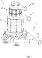
- eine Vorrichtung zum Aufbereiten eines aus Ersatzbrennstoff und Störstoff bestehenden Materialgemischs,
- Figur 2:
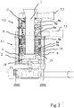
- eine Schnittdarstellung durch die Vorrichtung und
- Figur 3:
- eine Detailansicht der Vorrichtung.
- Figure 1:
- a device for processing a material mixture consisting of substitute fuel and contaminants,
- Figure 2:
- a sectional view through the device and
- Figure 3:
- a detailed view of the device.
Die in den Figuren dargestellte Vorrichtung zum Aufbereiten eines aus Ersatzbrennstoff und Störstoff bestehenden Materialgemischs weist eine vertikal ausgerichtete zentrale Zuführung 1 auf, die von einem Hohlzylinder 12 radial begrenzt ist. Oberhalb der Zuführung 1 ist ein Trichter ausgebildet, durch den das Materialgemisch in die Zuführung 1 eingegeben wird.The device shown in the figures for processing a material mixture consisting of substitute fuel and impurities has a vertically oriented
Unterhalb der zentralen Zuführung 1 ist eine Trenneinrichtung 2 ausgebildet, die einen Streuteller 14 umfasst. Der Streuteller 14 ist drehfest mit dem Hohlzylinder 12 verbunden, so dass der Streuteller 14 und der Hohlzylinder 12 gemeinsam drehend antreibbar sind.A
An der Außenseite des Hohlzylinders 12 sind Werkzeuge in Form von Flügelelementen 8a und Drähten 8b angeordnet, sodass diese gemeinsam mit dem Hohlzylinder 12 um die Hohlzylinderlängsachse drehend angetrieben werden können. Die Werkzeuge 8a, 8b bilden eine oberhalb der Trenneinrichtung 2 angeordnete Rotormühle 3 aus.Tools in the form of
Die Vorrichtung umfasst zudem eine Strömungseinrichtung 4 mit einem Einlass 15, einem ersten Auslass 7.1 und einem zweiten Auslass 7.2. Die Strömungseinrichtung 4 kann durch Einblasen eines gasförmigen Betriebsmediums am Einlass 15 oder durch Absaugen des gasförmigen Betriebsmediums an den Auslässen 7.1 und 7.2 betrieben werden. Die Vorrichtung ist dabei in ihrem Inneren so ausgebildet, dass das durch den Einlass 15 eintretende Betriebsmedium an der radial äußeren Kante des Streutellers 14 nach oben vorbei in die Rotormühle 3 strömt.The device also comprises a
Die Rotormühle 3 weist eine erste Stufe 5.1 auf, der der erste Auslass 7.1 zugeordnet ist. Die Rotormühle 3 weist zudem eine zweite Stufe 5.2 auf, der der zweite Auslass 7.2 zugeordnet ist. Die Werkzeuge 8a und 8b der ersten Stufe 5.1 sind radial von einer Gitteranordnung 10 umgeben, die die Werkzeuge von einem Ringraum 9 trennt. Zwischen der ersten Stufe 5.1 und der zweiten Stufe 5.2 ist zudem eine Trennvorrichtung 6 in Form eines Siebes ausgebildet.The
Die erste Stufe 5.1 und die zweite Stufe 5.2 der Rotormühle 3 umfassen jeweils eine Vielzahl von gruppenweise helixförmig an der Außenseite des Hohlzylinders 12 angebrachte Flügelelemente 8a, die sich von der Außenseite des Hohlzylinders radial nach außen erstrecken. Die Flügelelemente 8a sind mit einem Anstellwinkel zu einer horizontalen Ebene ausgerichtet. An den äußeren Enden der Flügelelemente 8a sind plattenförmige Prallelemente 13 angebracht. An einigen Flügelelementen 8a sind hingegen Kratzelemente 11 angebracht, mit denen von der Gitteranordnung 10 zurückgehaltene Bestandteile des Materialgemischs von der Gitteranordnung 10 losgelöst werden können. Im oberen Bereich der ersten Stufe 5.1 können zudem Kratzelemente als Säuberungseinrichtung mittelbar an dem Hohlzylinder 12 angebracht sein, mit denen von der Trennvorrichtung 6 zurückgehaltenes Material losgelöst werden kann. Im oberen Bereich weisen die erste Stufe 5.1 und die zweite Stufe 5.2 jeweils Drähte 8b als Werkzeuge auf, die an der Außenseite des Hohlzylinders 12 angebracht sind.The first stage 5.1 and the second stage 5.2 of the
Im Betrieb wird ein Materialgemisch, welches aus Ersatzbrennstoff und Störstoff besteht, in die vertikal ausgerichtete zentrale Zuführung 1 eingebracht, in welcher das Materialgemisch nach unten zu der den Streuteller 14 umfassenden Trenneinrichtung 2 absinkt. Durch die gemeinsame Drehbewegung des Streutellers 14 und des die Zuführung 1 begrenzenden Hohlzylinders 12 wird das Materialgemisch spätestens beim Erreichen des Streutellers 14 radial nach außen beschleunigt. Das über die äußere radiale Kante des Streutellers 14 tretende Materialgemisch wird aufgrund des aufsteigenden Gasstromes gesichtet, sodass vor allem Störstoff in dem den Streuteller 14 umgebenden Raum nach unten absinkt, während das hauptsächlich Ersatzbrennstoff aufweisende übrige Materialgemisch mit dem Gasstrom in die erste Stufe 5.1 der Rotormühle 3 eintritt.During operation, a material mixture consisting of substitute fuel and impurities is introduced into the vertically oriented
In der ersten Stufe 5.1 erfolgt eine Zerkleinerung des Materialgemischs durch Wechselwirkung mit den Werkzeugen 8a und 8b sowie untereinander. Aufgrund der vertikal und in Umfangsrichtung versetzten Anordnung der Werkzeuge 8a, 8b kann eine effektive Zerkleinerung erfolgen, wobei zerkleinertes Material durch die Gitteranordnung 10 in den Ringraum 9 hindurchtreten kann, wobei dieser Teil des Materialgemischs aus dem ersten Auslass 7.1 abgezogen wird.In the first stage 5.1, the material mixture is comminuted by interacting with the
Das durch die Trennvorrichtung 6 hindurchtretende Materialgemisch wird in der zweiten Stufe 5.2 weiter zerkleinert, sodass das aus dem zweiten Auslass 7.2 austretende Materialgemisch eine kleinere mittlere Partikelgröße aufweist als das aus dem ersten Auslass 7.1 austretende Materialgemisch.The material mixture passing through the
Mit der Vorrichtung kann also nicht nur eine besonders effiziente Zerkleinerung erfolgen, es kann vielmehr auch Materialgemisch mit unterschiedlicher Partikelgröße bereitgestellt werden.The device can therefore not only be used for particularly efficient comminution, but rather a material mixture with different particle sizes can also be provided.
- 11
- ZuführungFeed
- 22
- TrenneinrichtungSeparator
- 33
- RotormühleRotor mill
- 44th
- StrömungseinrichtungFlow device
- 5.15.1
- erste Stufefirst stage
- 5.25.2
- zweite Stufesecond step
- 66th
- TrennvorrichtungSeparator
- 7.17.1
- erster Auslassfirst outlet
- 7.27.2
- zweiter Auslasssecond outlet
- 8a8a
- FlügelelementWing element
- 8b8b
- Drahtwire
- 99
- RingraumAnnulus
- 1010
- GitteranordnungGrid arrangement
- 1111
- KratzelementScraping element
- 1212th
- HohlzylinderHollow cylinder
- 1313th
- PrallelementImpact element
- 1414th
- StreutellerSpreading plate
- 1515th
- Einlassinlet
Claims (11)
wobei das Materialgemisch in die Zuführung (1) einführbar ist und nach der Einführung in der Zuführung (1) zu der Trenneinrichtung (4) absinkt, wobei der Störstoff in der Trenneinrichtung (4) zumindest teilweise als eine Störstofffraktion aus dem Materialgemisch abgeschieden wird und das von den abgeschiedenen Störstoffen getrennte Materialgemisch mit dem Gasstrom zu der Rotormühle (3) aufsteigt, wobei das aufsteigende Materialgemisch in der Rotormühle (3) zerkleinert wird, wobei
die Rotormühle (3) mehrere vertikal und in Umfangsrichtung versetzt zueinander angeordnete Werkzeuge (8a, 8b) aufweist.
wherein the material mixture can be introduced into the feed (1) and, after being introduced into the feed (1), sinks to the separating device (4) The material mixture separated from the separated contaminants rises with the gas flow to the rotor mill (3), the rising material mixture being comminuted in the rotor mill (3), wherein
the rotor mill (3) has a plurality of tools (8a, 8b) arranged vertically and offset from one another in the circumferential direction.
Priority Applications (4)
| Application Number | Priority Date | Filing Date | Title |
|---|---|---|---|
| EP20159298.7A EP3871777A1 (en) | 2020-02-25 | 2020-02-25 | Device for treating a mixture of materials consisting of substitute fuel and impurity |
| BR102021003009-7A BR102021003009A2 (en) | 2020-02-25 | 2021-02-18 | DEVICE TO TREAT A MIXTURE OF MATERIAL CONSISTING OF REPLACEMENT FUEL AND CONTAMINANTS |
| US17/185,075 US20210260594A1 (en) | 2020-02-25 | 2021-02-25 | Device for Treatment of a Material Mixture Comprising of Substitute Fuel and Impurities |
| CN202110210157.7A CN113368998A (en) | 2020-02-25 | 2021-02-25 | Device for processing a material mixture consisting of alternative fuel and interfering substances |
Applications Claiming Priority (1)
| Application Number | Priority Date | Filing Date | Title |
|---|---|---|---|
| EP20159298.7A EP3871777A1 (en) | 2020-02-25 | 2020-02-25 | Device for treating a mixture of materials consisting of substitute fuel and impurity |
Publications (1)
| Publication Number | Publication Date |
|---|---|
| EP3871777A1 true EP3871777A1 (en) | 2021-09-01 |
Family
ID=69846201
Family Applications (1)
| Application Number | Title | Priority Date | Filing Date |
|---|---|---|---|
| EP20159298.7A Pending EP3871777A1 (en) | 2020-02-25 | 2020-02-25 | Device for treating a mixture of materials consisting of substitute fuel and impurity |
Country Status (4)
| Country | Link |
|---|---|
| US (1) | US20210260594A1 (en) |
| EP (1) | EP3871777A1 (en) |
| CN (1) | CN113368998A (en) |
| BR (1) | BR102021003009A2 (en) |
Families Citing this family (2)
| Publication number | Priority date | Publication date | Assignee | Title |
|---|---|---|---|---|
| PL3871776T3 (en) * | 2020-02-25 | 2022-11-21 | AUMUND Fördertechnik GmbH | Device for treating a mixture of materials consisting of substitute fuel and impurities |
| CN114602805B (en) * | 2022-03-09 | 2023-05-09 | 秦皇岛优格玛工业技术有限公司 | Screening equipment for silver-lead ore dressing |
Citations (3)
| Publication number | Priority date | Publication date | Assignee | Title |
|---|---|---|---|---|
| US2290379A (en) * | 1939-10-24 | 1942-07-21 | Peterson Clarence John | Pulverizing mill |
| US3003707A (en) * | 1955-02-14 | 1961-10-10 | Turbo Jet Milling Co Inc | Method and apparatus for reducing the size of particles |
| DE102015005604A1 (en) * | 2015-05-02 | 2016-11-03 | Udo Voges | Method and device for processing a material mixture consisting of substitute fuel and contaminant |
Family Cites Families (16)
| Publication number | Priority date | Publication date | Assignee | Title |
|---|---|---|---|---|
| US1636033A (en) * | 1926-03-10 | 1927-07-19 | Minerva A Brotherton | Centrifugal impact pulverizer |
| US1758010A (en) * | 1928-08-18 | 1930-05-13 | George F Pettinos | Grinding mill |
| US2329910A (en) * | 1941-01-27 | 1943-09-21 | Johnson Stanley | Pulverizing mill |
| US2695755A (en) * | 1951-01-02 | 1954-11-30 | John J Denovan | Method and apparatus for disintegrating raw materials |
| US2700511A (en) * | 1952-06-06 | 1955-01-25 | John J Denovan | Ore fiberizing machine |
| US3226045A (en) * | 1962-04-23 | 1965-12-28 | Gruendler Crusher And Pulveriz | Grinders |
| US3210015A (en) * | 1963-06-11 | 1965-10-05 | Tollemache Denys Herber George | Ballistic separator |
| US6543709B2 (en) * | 2001-01-12 | 2003-04-08 | Hosokawa Micron Powder Systems | Gravity flow air classifying mill |
| DE102005046207B4 (en) * | 2005-09-28 | 2014-12-24 | Get Hamburg Gmbh | Device for crushing debris |
| EP2837424A1 (en) * | 2013-08-13 | 2015-02-18 | TARTECH eco industries AG | Slag crusher |
| EP2939745B1 (en) * | 2014-05-02 | 2019-07-10 | Manuel Lindner | Device with impact zone |
| DE102016110086B4 (en) * | 2016-06-01 | 2019-09-26 | TARTECH eco industries AG | Device for separating conglomerates, which consist of materials of different density |
| DE102017205852B3 (en) * | 2017-04-06 | 2018-05-17 | Audi Ag | disk separator |
| CN207533374U (en) * | 2017-10-27 | 2018-06-26 | 联安海洋工程(天津)有限公司 | It is a kind of that there is the ore crusher of multiple stage crushing |
| IT201900002795A1 (en) * | 2019-02-27 | 2020-08-27 | Claudio Bano | PERFECTED CRUSHER |
| IT201900002797A1 (en) * | 2019-02-27 | 2020-08-27 | Claudio Bano | PERFECTED SHREDDER |
-
2020
- 2020-02-25 EP EP20159298.7A patent/EP3871777A1/en active Pending
-
2021
- 2021-02-18 BR BR102021003009-7A patent/BR102021003009A2/en unknown
- 2021-02-25 US US17/185,075 patent/US20210260594A1/en active Pending
- 2021-02-25 CN CN202110210157.7A patent/CN113368998A/en active Pending
Patent Citations (3)
| Publication number | Priority date | Publication date | Assignee | Title |
|---|---|---|---|---|
| US2290379A (en) * | 1939-10-24 | 1942-07-21 | Peterson Clarence John | Pulverizing mill |
| US3003707A (en) * | 1955-02-14 | 1961-10-10 | Turbo Jet Milling Co Inc | Method and apparatus for reducing the size of particles |
| DE102015005604A1 (en) * | 2015-05-02 | 2016-11-03 | Udo Voges | Method and device for processing a material mixture consisting of substitute fuel and contaminant |
Also Published As
| Publication number | Publication date |
|---|---|
| BR102021003009A2 (en) | 2021-09-08 |
| US20210260594A1 (en) | 2021-08-26 |
| CN113368998A (en) | 2021-09-10 |
Similar Documents
| Publication | Publication Date | Title |
|---|---|---|
| EP2851122B1 (en) | Comminuting device | |
| DE60300809T2 (en) | Apparatus for recovering plasterboard | |
| DE102012104031B4 (en) | Separating device for material conglomerates | |
| EP2668445B1 (en) | Processing of waste incineration ashes | |
| DE102011050789A1 (en) | Device for the mechanical separation of material conglomerates from materials of different density and / or consistency | |
| EP3871777A1 (en) | Device for treating a mixture of materials consisting of substitute fuel and impurity | |
| EP2646234B1 (en) | Device and method for separating composite materials | |
| EP3787796A1 (en) | System and method for an electrodynamic fragmentation | |
| EP3871776B1 (en) | Device for treating a mixture of materials consisting of substitute fuel and impurities | |
| EP0498017A1 (en) | Process for removing pollutants from contaminated material, more particularly from contaminated soil and rubble | |
| WO2018189369A1 (en) | Device and method for separating material composites | |
| DE4217703C2 (en) | Process and device for the pretreatment of polluted soils | |
| DE102016225248A1 (en) | Separator for polysilicon | |
| DE3836608C2 (en) | ||
| DE102012204050B4 (en) | Apparatus and method for processing silicon pieces | |
| DE3807017C2 (en) | ||
| EP0764470B1 (en) | Process for impact milling and impact mill | |
| WO1999061547A1 (en) | Installation and method for preparing remaining material from a thermal waste disposal facility | |
| EP2136937B1 (en) | Method and device for heat treatment including method and device for separating or classifying material to be fed | |
| EP0964748B1 (en) | Method and device for fragmenting bulk materials | |
| EP3431656A1 (en) | Device for the treatment of ballast stones and method therefore | |
| DE10018005A1 (en) | Method and device for reducing splinter material to powder feeds material to be processed through an inlet in an external wall into a processing chamber for shredding by a rotor. | |
| WO2000074854A1 (en) | Device for tearing metallic scrap | |
| DE4231100A1 (en) | Sepg. fibrous and spike components from fossil fuel, esp. xylitol from lignite - by comminuting on rotor fan mill, sepg. coarse spike or fibrous components on shaking screen, and passing remainder to centrifugal sieve | |
| EP2180962A1 (en) | Process and plant for obtaining metal parts from residues of waste incineration processes |
Legal Events
| Date | Code | Title | Description |
|---|---|---|---|
| PUAI | Public reference made under article 153(3) epc to a published international application that has entered the european phase |
Free format text: ORIGINAL CODE: 0009012 |
|
| STAA | Information on the status of an ep patent application or granted ep patent |
Free format text: STATUS: REQUEST FOR EXAMINATION WAS MADE |
|
| 17P | Request for examination filed |
Effective date: 20201113 |
|
| AK | Designated contracting states |
Kind code of ref document: A1 Designated state(s): AL AT BE BG CH CY CZ DE DK EE ES FI FR GB GR HR HU IE IS IT LI LT LU LV MC MK MT NL NO PL PT RO RS SE SI SK SM TR |
|
| STAA | Information on the status of an ep patent application or granted ep patent |
Free format text: STATUS: EXAMINATION IS IN PROGRESS |
|
| 17Q | First examination report despatched |
Effective date: 20220426 |