EP3871777A1 - Dispositif de traitement d'un mélange de matières comprenant un carburant de remplacement et des substances interférentes - Google Patents
Dispositif de traitement d'un mélange de matières comprenant un carburant de remplacement et des substances interférentes Download PDFInfo
- Publication number
- EP3871777A1 EP3871777A1 EP20159298.7A EP20159298A EP3871777A1 EP 3871777 A1 EP3871777 A1 EP 3871777A1 EP 20159298 A EP20159298 A EP 20159298A EP 3871777 A1 EP3871777 A1 EP 3871777A1
- Authority
- EP
- European Patent Office
- Prior art keywords
- rotor mill
- material mixture
- tools
- feed
- separating device
- Prior art date
- Legal status (The legal status is an assumption and is not a legal conclusion. Google has not performed a legal analysis and makes no representation as to the accuracy of the status listed.)
- Granted
Links
- 239000000203 mixture Substances 0.000 title claims abstract description 53
- 239000000446 fuel Substances 0.000 title claims abstract description 26
- 239000012535 impurity Substances 0.000 title claims abstract description 10
- 239000000463 material Substances 0.000 title description 3
- 239000000356 contaminant Substances 0.000 claims description 7
- 238000007790 scraping Methods 0.000 claims description 7
- 230000000630 rising effect Effects 0.000 claims description 6
- 239000002245 particle Substances 0.000 description 11
- 230000000717 retained effect Effects 0.000 description 7
- 238000000926 separation method Methods 0.000 description 6
- 238000004140 cleaning Methods 0.000 description 3
- 238000011161 development Methods 0.000 description 2
- 230000018109 developmental process Effects 0.000 description 2
- 238000000034 method Methods 0.000 description 2
- 239000002910 solid waste Substances 0.000 description 2
- 235000008733 Citrus aurantifolia Nutrition 0.000 description 1
- 235000011941 Tilia x europaea Nutrition 0.000 description 1
- 238000009825 accumulation Methods 0.000 description 1
- 238000007664 blowing Methods 0.000 description 1
- 239000004568 cement Substances 0.000 description 1
- 230000001419 dependent effect Effects 0.000 description 1
- 239000010791 domestic waste Substances 0.000 description 1
- 238000001035 drying Methods 0.000 description 1
- 239000011521 glass Substances 0.000 description 1
- 239000002440 industrial waste Substances 0.000 description 1
- 230000003993 interaction Effects 0.000 description 1
- 239000003077 lignite Substances 0.000 description 1
- 239000004571 lime Substances 0.000 description 1
- 239000002184 metal Substances 0.000 description 1
- 229910052751 metal Inorganic materials 0.000 description 1
- 150000002739 metals Chemical class 0.000 description 1
- 230000010349 pulsation Effects 0.000 description 1
- 238000006748 scratching Methods 0.000 description 1
- 230000002393 scratching effect Effects 0.000 description 1
- 238000004056 waste incineration Methods 0.000 description 1
Images

Classifications
-
- B—PERFORMING OPERATIONS; TRANSPORTING
- B02—CRUSHING, PULVERISING, OR DISINTEGRATING; PREPARATORY TREATMENT OF GRAIN FOR MILLING
- B02C—CRUSHING, PULVERISING, OR DISINTEGRATING IN GENERAL; MILLING GRAIN
- B02C23/00—Auxiliary methods or auxiliary devices or accessories specially adapted for crushing or disintegrating not provided for in preceding groups or not specially adapted to apparatus covered by a single preceding group
- B02C23/18—Adding fluid, other than for crushing or disintegrating by fluid energy
- B02C23/24—Passing gas through crushing or disintegrating zone
- B02C23/30—Passing gas through crushing or disintegrating zone the applied gas acting to effect material separation
-
- B—PERFORMING OPERATIONS; TRANSPORTING
- B02—CRUSHING, PULVERISING, OR DISINTEGRATING; PREPARATORY TREATMENT OF GRAIN FOR MILLING
- B02C—CRUSHING, PULVERISING, OR DISINTEGRATING IN GENERAL; MILLING GRAIN
- B02C13/00—Disintegrating by mills having rotary beater elements ; Hammer mills
- B02C13/14—Disintegrating by mills having rotary beater elements ; Hammer mills with vertical rotor shaft, e.g. combined with sifting devices
- B02C13/16—Disintegrating by mills having rotary beater elements ; Hammer mills with vertical rotor shaft, e.g. combined with sifting devices with beaters hinged to the rotor
-
- B—PERFORMING OPERATIONS; TRANSPORTING
- B02—CRUSHING, PULVERISING, OR DISINTEGRATING; PREPARATORY TREATMENT OF GRAIN FOR MILLING
- B02C—CRUSHING, PULVERISING, OR DISINTEGRATING IN GENERAL; MILLING GRAIN
- B02C13/00—Disintegrating by mills having rotary beater elements ; Hammer mills
- B02C13/14—Disintegrating by mills having rotary beater elements ; Hammer mills with vertical rotor shaft, e.g. combined with sifting devices
- B02C13/18—Disintegrating by mills having rotary beater elements ; Hammer mills with vertical rotor shaft, e.g. combined with sifting devices with beaters rigidly connected to the rotor
-
- B—PERFORMING OPERATIONS; TRANSPORTING
- B02—CRUSHING, PULVERISING, OR DISINTEGRATING; PREPARATORY TREATMENT OF GRAIN FOR MILLING
- B02C—CRUSHING, PULVERISING, OR DISINTEGRATING IN GENERAL; MILLING GRAIN
- B02C13/00—Disintegrating by mills having rotary beater elements ; Hammer mills
- B02C13/26—Details
- B02C13/282—Shape or inner surface of mill-housings
- B02C13/284—Built-in screens
-
- B—PERFORMING OPERATIONS; TRANSPORTING
- B02—CRUSHING, PULVERISING, OR DISINTEGRATING; PREPARATORY TREATMENT OF GRAIN FOR MILLING
- B02C—CRUSHING, PULVERISING, OR DISINTEGRATING IN GENERAL; MILLING GRAIN
- B02C23/00—Auxiliary methods or auxiliary devices or accessories specially adapted for crushing or disintegrating not provided for in preceding groups or not specially adapted to apparatus covered by a single preceding group
- B02C23/02—Feeding devices
-
- B—PERFORMING OPERATIONS; TRANSPORTING
- B02—CRUSHING, PULVERISING, OR DISINTEGRATING; PREPARATORY TREATMENT OF GRAIN FOR MILLING
- B02C—CRUSHING, PULVERISING, OR DISINTEGRATING IN GENERAL; MILLING GRAIN
- B02C23/00—Auxiliary methods or auxiliary devices or accessories specially adapted for crushing or disintegrating not provided for in preceding groups or not specially adapted to apparatus covered by a single preceding group
- B02C23/08—Separating or sorting of material, associated with crushing or disintegrating
- B02C23/16—Separating or sorting of material, associated with crushing or disintegrating with separator defining termination of crushing or disintegrating zone, e.g. screen denying egress of oversize material
-
- B—PERFORMING OPERATIONS; TRANSPORTING
- B02—CRUSHING, PULVERISING, OR DISINTEGRATING; PREPARATORY TREATMENT OF GRAIN FOR MILLING
- B02C—CRUSHING, PULVERISING, OR DISINTEGRATING IN GENERAL; MILLING GRAIN
- B02C23/00—Auxiliary methods or auxiliary devices or accessories specially adapted for crushing or disintegrating not provided for in preceding groups or not specially adapted to apparatus covered by a single preceding group
- B02C23/18—Adding fluid, other than for crushing or disintegrating by fluid energy
-
- B—PERFORMING OPERATIONS; TRANSPORTING
- B02—CRUSHING, PULVERISING, OR DISINTEGRATING; PREPARATORY TREATMENT OF GRAIN FOR MILLING
- B02C—CRUSHING, PULVERISING, OR DISINTEGRATING IN GENERAL; MILLING GRAIN
- B02C13/00—Disintegrating by mills having rotary beater elements ; Hammer mills
- B02C13/26—Details
- B02C13/288—Ventilating, or influencing air circulation
-
- B—PERFORMING OPERATIONS; TRANSPORTING
- B02—CRUSHING, PULVERISING, OR DISINTEGRATING; PREPARATORY TREATMENT OF GRAIN FOR MILLING
- B02C—CRUSHING, PULVERISING, OR DISINTEGRATING IN GENERAL; MILLING GRAIN
- B02C13/00—Disintegrating by mills having rotary beater elements ; Hammer mills
- B02C13/26—Details
- B02C13/28—Shape or construction of beater elements
- B02C2013/2812—Shape or construction of beater elements the beater elements are attached to a hollow cylindrical rotor
-
- B—PERFORMING OPERATIONS; TRANSPORTING
- B02—CRUSHING, PULVERISING, OR DISINTEGRATING; PREPARATORY TREATMENT OF GRAIN FOR MILLING
- B02C—CRUSHING, PULVERISING, OR DISINTEGRATING IN GENERAL; MILLING GRAIN
- B02C23/00—Auxiliary methods or auxiliary devices or accessories specially adapted for crushing or disintegrating not provided for in preceding groups or not specially adapted to apparatus covered by a single preceding group
- B02C23/08—Separating or sorting of material, associated with crushing or disintegrating
- B02C23/16—Separating or sorting of material, associated with crushing or disintegrating with separator defining termination of crushing or disintegrating zone, e.g. screen denying egress of oversize material
- B02C2023/165—Screen denying egress of oversize material
-
- B—PERFORMING OPERATIONS; TRANSPORTING
- B02—CRUSHING, PULVERISING, OR DISINTEGRATING; PREPARATORY TREATMENT OF GRAIN FOR MILLING
- B02C—CRUSHING, PULVERISING, OR DISINTEGRATING IN GENERAL; MILLING GRAIN
- B02C2201/00—Codes relating to disintegrating devices adapted for specific materials
- B02C2201/06—Codes relating to disintegrating devices adapted for specific materials for garbage, waste or sewage
Definitions
- the present invention relates to a method for processing a material mixture consisting of substitute fuel and impurities, which is sifted, comminuted and dried in the device.
- the substitute fuel also known as secondary fuel, includes in particular solid waste, which can be used together with conventional fuels, especially in cement, lime, lignite or industrial power plants as well as in waste incineration plants or as the sole fuel in substitute fuel power plants.
- the solid waste for example, consisting of commercial waste and / or household waste, generally still contains contaminants such as glass or metals after being roughly shredded. It is therefore known to carry out a separation after the coarse comminution and, if necessary, to comminute the substitute fuel further.
- the object of the present invention is therefore to provide a device with which both the impurities can be separated from the substitute fuel and the substitute fuel can be generated with a different mean size of the substitute fuel particles.
- the object is achieved by a device for processing a material mixture consisting of substitute fuel and impurities, having a vertically oriented central feed, a separating device arranged below the central feed, a rotor mill, the rotor mill being arranged above the separating device and surrounding the central feed, and a flow device for generating an upwardly directed gas flow, wherein the material mixture can be introduced into the feed and sinks after the introduction into the feed to the separating device, wherein the contaminant in the separating device is at least partially separated as a contaminant fraction from the material mixture and that of the separated material mixture rises with the gas flow to the rotor mill, the rising material mixture being comminuted in the rotor mill.
- the rotor mill has a plurality of tools arranged vertically and offset from one another in the circumferential direction.
- the material mixture can, for example, be introduced into the feed via a funnel or another feeding device, the feed being aligned vertically so that the material mixture introduced into the feed sinks in the feed.
- the feed is hollow on the inside so that the material mixture can sink undisturbed.
- the feed can be formed by a tube (hollow cylinder).
- a separating device is arranged below the central feed, which includes, for example, a rotatably drivable spreading plate.
- the separating device is designed in particular so that at least a large proportion of the Contaminants from the material mixture can be separated (sifted), wherein the separated contaminants can be removed from the device in a suitable manner.
- a flow device for separation / sifting, by means of which an upwardly rising gas flow can be generated at least in the area of the separation device, in particular in the area of the spreading plate of the separation device, and the rotor mill.
- the flow device has in particular at least one gas inlet preferably arranged in the lower region of the device and at least one outlet in the upper region of the rotor mill.
- heated air can be used as the gas.
- the material mixture supplied through the central feed is thrown from the spreading plate into a space surrounding the spreading plate, in which the gas flow rises, with the rising gas flow only taking the substitute fuel with it, if possible, and a large part of the impurities in the spreading plate surrounding space drops.
- the substitute fuel that has been taken along is then also dried with the gas flow.
- the substitute fuel carried along by the gas flow (and any impurities that have not been separated off) is fed with the gas flow to the rotor mill, which is arranged above the separating device (spreading plate).
- the substitute fuel is crushed in the rotor mill by impact, shear and impact forces.
- the rotor mill preferably has at least one rotationally driven tool which promotes the comminution of the substitute fuel.
- the separating device (and in particular its spreading plate) and the tools of the rotor mill can preferably be driven together to rotate (rotationally) about a vertically aligned axis.
- the feed can also be driven to rotate at the same time.
- the spreading plate can be non-rotatably connected to the element delimiting the feed (for example a pipe), the at least one tool of the rotor mill preferably being attached to an outside of the element forming the central feed inside.
- only one drive has to be provided for generating the rotary movement.
- the drive is arranged in particular in the lower region of the device and can, for example, generate a rotary movement with 500 to 1000, preferably with 700 to 900 revolutions / min.
- the invention also provides that the rotor mill (and in particular also each stage of the rotor mill) has a plurality of, in particular more than 10, preferably more than 20 tools arranged vertically and offset from one another in the circumferential direction.
- This arrangement of the tools, offset both in the circumferential direction and in the vertical direction, results in a longer dwell time of the material mixture and thus more effective comminution of the material mixture, so that a higher degree of comminution can be achieved or the rotor mill can be realized with a lower height.
- the longer dwell time also improves the drying of the material mixture.
- the rotor mill has a centrally arranged and rotationally driven hollow cylinder (which preferably also forms the central feed), on the outside of which the tools are attached, the tools each extending individually radially outward from the outside of the hollow cylinder .
- the tools are in particular elongated elements that differ from the Hollow cylinder extend outward.
- a group of tools and / or most tools include flat wing elements that extend radially outward.
- the wing elements are attached directly or indirectly to the outside of the hollow cylinder and are considerably longer in the radial direction (at least three times, preferably at least five times) as long as their width.
- the wing elements have a height which is less than their width, the wing elements being at least twice, preferably four times as wide as they are high. It has been found that a particularly efficient comminution of the material mixture is possible with such wing-like elements.
- a further improvement in the comminution can be achieved in that the wing elements are positioned at an angle to a horizontal plane.
- the setting angle is preferably 3 ° to 45 °, particularly preferably 5 ° to 20 °, to the horizontal plane.
- At least one tool or a plurality of tools comprises a plate-shaped impact element which is arranged at a radial end of the tool, the plate-shaped impact element being particularly vertically aligned.
- the plate-shaped impact element With such a plate-shaped impact element, the comminution efficiency can be further increased.
- At least one tool comprises a scraping element which is arranged radially on the outside of the tool and is in contact with a wall of the rotor mill or the stage of the rotor mill that delimits the grinding chamber on the outside, the wall being formed, for example, by a grid arrangement can that separates the grinding chamber from an annulus.
- a scraping element which is arranged radially on the outside of the tool and is in contact with a wall of the rotor mill or the stage of the rotor mill that delimits the grinding chamber on the outside, the wall being formed, for example, by a grid arrangement can that separates the grinding chamber from an annulus.
- the plate-shaped impact element or the scraping element can, for example, be attached to a radial end of the previously described wing element of the tool.
- At least one tool is formed from a wire which is attached to the outside of the hollow cylinder.
- a wire is understood in particular to be such an element which extends outwardly from the hollow cylinder and whose width and height are approximately the same.
- the wire preferably has a circular cross-sectional configuration.
- a plurality (in particular more than 8, preferably more than 16) of tools are preferably arranged in a lower area of the rotor mill or in a lower area of a stage of the rotor mill, each of which comprises a vane element, while in an upper area of the rotor mill or in one
- a plurality of tools comprising a wire are arranged in the upper region of a stage of the rotor mill.
- a group (more than 4) of tools can be arranged helically offset from one another (i.e. on a helical line), whereby several groups of tools can be arranged one behind the other in the circumferential direction.
- the rotor mill is multi-stage, i.e. has at least and preferably exactly two or three stages, optionally four stages, with at least one separating device (for example a sieve) being arranged between the stages of the rotor mill
- Separation device not retained material mixture is further comminuted in the following stage, in particular particles of the mainly substitute fuel containing material mixture with a particle size specified by the separation device are retained in the previous stage, while particles of the material mixture with a smaller size can get into the following stage .
- the material mixture is then comminuted further.
- the multi-stage rotor mill means that one device can provide substitute fuel with different mean particle sizes.
- the fraction of the material mixture withdrawn from the first stage can, for example, have an average particle size between 60 and 200 mm, while the fraction of the material mixture withdrawn from the second stage can have an average particle size of, for example, 10 to 60 mm.
- At least one outlet is assigned to each stage of the rotor mill, via which the correspondingly comminuted material mixture, which mainly or at best exclusively contains substitute fuel, can be drawn off.
- the second and, if appropriate, any further stage of the rotor mill are arranged in particular vertically above the first or preceding stage, the tools of each stage preferably being driven by a single common drive.
- the separating device comprises at least one sieve in each case between the stages of the rotor mill.
- a simple separating device is provided with such a sieve.
- annular space is formed which surrounds the first stage of the rotor mill, in particular a grid arrangement functioning as a sieve being arranged between the outer annular space and the tools of the first stage of the rotor mill.
- the material mixture comminuted in the first stage of the rotor mill can thus pass through the grid arrangement into the annular space, from which the comminuted material mixture can be withdrawn through the at least one first outlet. If a plurality (more than two) stages are formed, each stage following the first stage up to the last stage can also be assigned its own annular space which is separated from the tools of the corresponding stage by a grid arrangement.
- the separating device is assigned a cleaning device between the stages of the rotor mill, with which the material mixture retained by the separating device can be released from the separating device.
- the dissolved material mixture can thus be fed to a further comminution in the preceding stage, for which purpose, for example, a pulsation of the gas flow is also possible.
- the cleaning device can also be rotatably driven together with the tools of the previous stage, so that a continuous release of the retained material mixture from the separating device is possible.
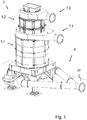
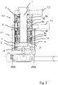
- the device shown in the figures for processing a material mixture consisting of substitute fuel and impurities has a vertically oriented central feed 1 which is radially delimited by a hollow cylinder 12.
- a funnel is formed above the feed 1 through which the material mixture is fed into the feed 1.
- a separating device 2 which comprises a spreading plate 14, is formed below the central feed 1.
- the spreading plate 14 is non-rotatably connected to the hollow cylinder 12, so that the spreading plate 14 and the hollow cylinder 12 can be driven to rotate together.
- Tools in the form of wing elements 8a and wires 8b are arranged on the outside of the hollow cylinder 12, so that they can be driven to rotate together with the hollow cylinder 12 about the longitudinal axis of the hollow cylinder.
- the tools 8a, 8b form a rotor mill 3 arranged above the separating device 2.
- the device also comprises a flow device 4 with an inlet 15, a first outlet 7.1 and a second outlet 7.2.
- the flow device 4 can be operated by blowing in a gaseous operating medium at the inlet 15 or by sucking off the gaseous operating medium at the outlets 7.1 and 7.2.
- the interior of the device is designed in such a way that the operating medium entering through the inlet 15 flows upwards past the radially outer edge of the spreading plate 14 into the rotor mill 3.
- the rotor mill 3 has a first stage 5.1 to which the first outlet 7.1 is assigned.
- the rotor mill 3 also has a second stage 5.2, to which the second outlet 7.2 is assigned.
- the tools 8a and 8b of the first stage 5.1 are radially surrounded by a grid arrangement 10 which separates the tools from an annular space 9.
- a separating device 6 in the form of a sieve is formed between the first stage 5.1 and the second stage 5.2.
- the first stage 5.1 and the second stage 5.2 of the rotor mill 3 each comprise a multiplicity of vane elements 8a which are attached in groups in a helical manner to the outside of the hollow cylinder 12 and which extend from the outside of the hollow cylinder extend radially outward.
- the wing elements 8a are aligned with an angle of attack to a horizontal plane.
- Plate-shaped impact elements 13 are attached to the outer ends of the wing elements 8a.
- scraping elements 11 are attached to some wing elements 8a, with which components of the material mixture retained by the grid arrangement 10 can be detached from the grid arrangement 10.
- scratching elements can also be attached indirectly to the hollow cylinder 12 as a cleaning device, with which material retained by the separating device 6 can be detached.
- the first stage 5.1 and the second stage 5.2 each have wires 8b as tools, which are attached to the outside of the hollow cylinder 12.
- a material mixture consisting of substitute fuel and impurities is introduced into the vertically oriented central feed 1, in which the material mixture sinks down to the separating device 2 comprising the spreading plate 14.
- the material mixture is accelerated radially outwards when it reaches the spreading plate 14 at the latest.
- the material mixture passing over the outer radial edge of the spreading plate 14 is sifted due to the rising gas flow, so that above all foreign matter in the space surrounding the spreading plate 14 sinks down, while the remaining material mixture, mainly containing substitute fuel, with the gas flow into the first stage 5.1 of the rotor mill 3 entry.
- the material mixture is comminuted by interacting with the tools 8a and 8b as well as with each other. Due to the vertically and circumferentially offset arrangement of the tools 8a, 8b, effective comminution can take place, with comminuted Material can pass through the grid arrangement 10 into the annular space 9, this part of the material mixture being withdrawn from the first outlet 7.1.
- the material mixture passing through the separating device 6 is further comminuted in the second stage 5.2, so that the material mixture exiting from the second outlet 7.2 has a smaller mean particle size than the material mixture exiting from the first outlet 7.1.
- the device can therefore not only be used for particularly efficient comminution, but rather a material mixture with different particle sizes can also be provided.
Landscapes
- Engineering & Computer Science (AREA)
- Food Science & Technology (AREA)
- Crushing And Grinding (AREA)
- Disintegrating Or Milling (AREA)
- Processing Of Solid Wastes (AREA)
Priority Applications (4)
| Application Number | Priority Date | Filing Date | Title |
|---|---|---|---|
| EP20159298.7A EP3871777B1 (fr) | 2020-02-25 | 2020-02-25 | Dispositif de traitement d'un mélange de matières comprenant un carburant de remplacement et des impuretés |
| BR102021003009-7A BR102021003009A2 (pt) | 2020-02-25 | 2021-02-18 | Dispositivo para tratar uma mistura de material que consiste em combustível de substituição e contaminantes |
| US17/185,075 US12048934B2 (en) | 2020-02-25 | 2021-02-25 | Device for treatment of a material mixture comprising of substitute fuel and impurities |
| CN202110210157.7A CN113368998B (zh) | 2020-02-25 | 2021-02-25 | 用于处理由替代燃料和干扰物质组成的材料混合物的设备 |
Applications Claiming Priority (1)
| Application Number | Priority Date | Filing Date | Title |
|---|---|---|---|
| EP20159298.7A EP3871777B1 (fr) | 2020-02-25 | 2020-02-25 | Dispositif de traitement d'un mélange de matières comprenant un carburant de remplacement et des impuretés |
Publications (2)
| Publication Number | Publication Date |
|---|---|
| EP3871777A1 true EP3871777A1 (fr) | 2021-09-01 |
| EP3871777B1 EP3871777B1 (fr) | 2024-08-28 |
Family
ID=69846201
Family Applications (1)
| Application Number | Title | Priority Date | Filing Date |
|---|---|---|---|
| EP20159298.7A Active EP3871777B1 (fr) | 2020-02-25 | 2020-02-25 | Dispositif de traitement d'un mélange de matières comprenant un carburant de remplacement et des impuretés |
Country Status (4)
| Country | Link |
|---|---|
| US (1) | US12048934B2 (fr) |
| EP (1) | EP3871777B1 (fr) |
| CN (1) | CN113368998B (fr) |
| BR (1) | BR102021003009A2 (fr) |
Families Citing this family (3)
| Publication number | Priority date | Publication date | Assignee | Title |
|---|---|---|---|---|
| PL3871776T3 (pl) * | 2020-02-25 | 2022-11-21 | AUMUND Fördertechnik GmbH | Urządzenie do przetwarzania mieszaniny materiałowej składającej się z paliwa zastępczego i materiału zanieczyszczającego |
| IT202000008065A1 (it) * | 2020-04-16 | 2021-10-16 | Ecomade Eng Srl | Apparato separatore di rifiuti |
| CN114602805B (zh) * | 2022-03-09 | 2023-05-09 | 秦皇岛优格玛工业技术有限公司 | 一种银铅矿选矿用的筛分设备 |
Citations (3)
| Publication number | Priority date | Publication date | Assignee | Title |
|---|---|---|---|---|
| US2290379A (en) * | 1939-10-24 | 1942-07-21 | Peterson Clarence John | Pulverizing mill |
| US3003707A (en) * | 1955-02-14 | 1961-10-10 | Turbo Jet Milling Co Inc | Method and apparatus for reducing the size of particles |
| DE102015005604A1 (de) * | 2015-05-02 | 2016-11-03 | Udo Voges | Verfahren und Vorrichtung zum Aufbereiten eines aus Ersatzbrennstoff und Störstoff bestehenden Materialgemischs |
Family Cites Families (16)
| Publication number | Priority date | Publication date | Assignee | Title |
|---|---|---|---|---|
| US1636033A (en) * | 1926-03-10 | 1927-07-19 | Minerva A Brotherton | Centrifugal impact pulverizer |
| US1758010A (en) * | 1928-08-18 | 1930-05-13 | George F Pettinos | Grinding mill |
| US2329910A (en) * | 1941-01-27 | 1943-09-21 | Johnson Stanley | Pulverizing mill |
| US2695755A (en) * | 1951-01-02 | 1954-11-30 | John J Denovan | Method and apparatus for disintegrating raw materials |
| US2700511A (en) * | 1952-06-06 | 1955-01-25 | John J Denovan | Ore fiberizing machine |
| US3226045A (en) * | 1962-04-23 | 1965-12-28 | Gruendler Crusher And Pulveriz | Grinders |
| US3210015A (en) * | 1963-06-11 | 1965-10-05 | Tollemache Denys Herber George | Ballistic separator |
| US6543709B2 (en) * | 2001-01-12 | 2003-04-08 | Hosokawa Micron Powder Systems | Gravity flow air classifying mill |
| DE102005046207B4 (de) * | 2005-09-28 | 2014-12-24 | Get Hamburg Gmbh | Vorrichtung zum Zerkleinern von Haufwerk |
| EP2837424A1 (fr) * | 2013-08-13 | 2015-02-18 | TARTECH eco industries AG | Briseur de scories |
| EP2939745B1 (fr) * | 2014-05-02 | 2019-07-10 | Manuel Lindner | Dispositif doté de chambre à impact |
| DE102016110086B4 (de) * | 2016-06-01 | 2019-09-26 | TARTECH eco industries AG | Vorrichtung zum Auftrennen von Konglomeraten, die aus Materialien unterschiedlicher Dichte bestehen |
| DE102017205852B3 (de) * | 2017-04-06 | 2018-05-17 | Audi Ag | Tellerseparator |
| CN207533374U (zh) | 2017-10-27 | 2018-06-26 | 联安海洋工程(天津)有限公司 | 一种具有多级破碎功能的矿石破碎机 |
| IT201900002795A1 (it) * | 2019-02-27 | 2020-08-27 | Claudio Bano | Frantumatore perfezionato |
| IT201900002797A1 (it) * | 2019-02-27 | 2020-08-27 | Claudio Bano | Trituratore perfezionato |
-
2020
- 2020-02-25 EP EP20159298.7A patent/EP3871777B1/fr active Active
-
2021
- 2021-02-18 BR BR102021003009-7A patent/BR102021003009A2/pt unknown
- 2021-02-25 US US17/185,075 patent/US12048934B2/en active Active
- 2021-02-25 CN CN202110210157.7A patent/CN113368998B/zh active Active
Patent Citations (3)
| Publication number | Priority date | Publication date | Assignee | Title |
|---|---|---|---|---|
| US2290379A (en) * | 1939-10-24 | 1942-07-21 | Peterson Clarence John | Pulverizing mill |
| US3003707A (en) * | 1955-02-14 | 1961-10-10 | Turbo Jet Milling Co Inc | Method and apparatus for reducing the size of particles |
| DE102015005604A1 (de) * | 2015-05-02 | 2016-11-03 | Udo Voges | Verfahren und Vorrichtung zum Aufbereiten eines aus Ersatzbrennstoff und Störstoff bestehenden Materialgemischs |
Also Published As
| Publication number | Publication date |
|---|---|
| US20210260594A1 (en) | 2021-08-26 |
| BR102021003009A2 (pt) | 2021-09-08 |
| EP3871777B1 (fr) | 2024-08-28 |
| CN113368998B (zh) | 2024-09-13 |
| US12048934B2 (en) | 2024-07-30 |
| CN113368998A (zh) | 2021-09-10 |
Similar Documents
| Publication | Publication Date | Title |
|---|---|---|
| EP3871777B1 (fr) | Dispositif de traitement d'un mélange de matières comprenant un carburant de remplacement et des impuretés | |
| EP2851122B1 (fr) | Dispositif de concassage | |
| DE60300809T2 (de) | Vorrichtung zur Wiedergewinnung von Gipskartonplatten | |
| DE102012104031B4 (de) | Trennvorrichtung für Materialkonglomerate | |
| EP3871776B1 (fr) | Dispositif de traitement d'un mélange de matériaux comprenant du carburant de remplacement et des impuretés | |
| EP2646234B1 (fr) | Dispositif et procede de séparation de matériaux composites | |
| DE102011050789A1 (de) | Vorrichtung zum mechanischen Trennen von Materialkonglomeraten aus Materialen unterschiedlicher Dichte und/oder Konsistenz | |
| DE69904013T2 (de) | Verfahren und vorrichtung zur zerkleinerung von abfall, auch für nicht dafür vorgesehenen abfall | |
| WO2019207108A1 (fr) | Installation et procédé de fragmentation électrodynamique | |
| EP1088043B1 (fr) | Installation de traitement de matiere residuelle provenant d'une installation thermique d'elimination des dechets | |
| EP3609620A1 (fr) | Dispositif et procédé de séparation de matières composites | |
| DE102007040225A1 (de) | Verfahren und Anlage zur Gewinnung von Metallteilen aus Rückständen von Müllverbrennungsprozessen | |
| DE4217703C2 (de) | Verfahren und Vorrichtung zur Vorbehandlung von schadstoffbelasteten Böden | |
| DE102016225248A1 (de) | Abscheidevorrichtung für Polysilicium | |
| DE3836608C2 (fr) | ||
| DE102012204050B4 (de) | Vorrichtung und Verfahren zum Bearbeiten von Silizium-Stücken | |
| DE3807017C2 (fr) | ||
| EP0764470B1 (fr) | Procédé pour mouture à percussion et broyeur à choc | |
| DE10018005A1 (de) | Verfahren und Vorrichtung zum Pulverisieren von spanartigem Material | |
| WO2000074854A1 (fr) | Dispositif permettant de dechiqueter des dechets metalliques | |
| WO2016066806A1 (fr) | Procédé de manipulation de scorie et de matériau tombant à travers une grille d'une installation d'incinération de déchets et installation d'incinération de déchets | |
| EP2180962A1 (fr) | Procédé et équipement de production de morceaux de métal à partir des résidus d'incinération des ordures | |
| EP0964748A1 (fr) | Procede et dispositif pour broyer des materiaux en vrac | |
| WO2022008312A1 (fr) | Procédé de récupération de métaux non ferreux à partir des cendres des installations d'incinération de déchets ménagers et des résidus de processus thermiques | |
| WO1993003844A1 (fr) | Procede et dispositif de broyage |
Legal Events
| Date | Code | Title | Description |
|---|---|---|---|
| PUAI | Public reference made under article 153(3) epc to a published international application that has entered the european phase |
Free format text: ORIGINAL CODE: 0009012 |
|
| STAA | Information on the status of an ep patent application or granted ep patent |
Free format text: STATUS: REQUEST FOR EXAMINATION WAS MADE |
|
| 17P | Request for examination filed |
Effective date: 20201113 |
|
| AK | Designated contracting states |
Kind code of ref document: A1 Designated state(s): AL AT BE BG CH CY CZ DE DK EE ES FI FR GB GR HR HU IE IS IT LI LT LU LV MC MK MT NL NO PL PT RO RS SE SI SK SM TR |
|
| STAA | Information on the status of an ep patent application or granted ep patent |
Free format text: STATUS: EXAMINATION IS IN PROGRESS |
|
| 17Q | First examination report despatched |
Effective date: 20220426 |
|
| GRAP | Despatch of communication of intention to grant a patent |
Free format text: ORIGINAL CODE: EPIDOSNIGR1 |
|
| STAA | Information on the status of an ep patent application or granted ep patent |
Free format text: STATUS: GRANT OF PATENT IS INTENDED |
|
| INTG | Intention to grant announced |
Effective date: 20240508 |
|
| GRAS | Grant fee paid |
Free format text: ORIGINAL CODE: EPIDOSNIGR3 |
|
| GRAA | (expected) grant |
Free format text: ORIGINAL CODE: 0009210 |
|
| STAA | Information on the status of an ep patent application or granted ep patent |
Free format text: STATUS: THE PATENT HAS BEEN GRANTED |
|
| AK | Designated contracting states |
Kind code of ref document: B1 Designated state(s): AL AT BE BG CH CY CZ DE DK EE ES FI FR GB GR HR HU IE IS IT LI LT LU LV MC MK MT NL NO PL PT RO RS SE SI SK SM TR |
|
| REG | Reference to a national code |
Ref country code: CH Ref legal event code: EP |
|
| REG | Reference to a national code |
Ref country code: DE Ref legal event code: R096 Ref document number: 502020008989 Country of ref document: DE |