EP3871014B1 - Imagerie par rayons x pulsée - Google Patents
Imagerie par rayons x pulsée Download PDFInfo
- Publication number
- EP3871014B1 EP3871014B1 EP19882323.9A EP19882323A EP3871014B1 EP 3871014 B1 EP3871014 B1 EP 3871014B1 EP 19882323 A EP19882323 A EP 19882323A EP 3871014 B1 EP3871014 B1 EP 3871014B1
- Authority
- EP
- European Patent Office
- Prior art keywords
- ray
- time
- photons
- pulsed
- sensitive
- Prior art date
- Legal status (The legal status is an assumption and is not a legal conclusion. Google has not performed a legal analysis and makes no representation as to the accuracy of the status listed.)
- Active
Links
- 238000003384 imaging method Methods 0.000 title claims description 53
- 238000001514 detection method Methods 0.000 claims description 38
- 238000005259 measurement Methods 0.000 claims description 21
- 230000005855 radiation Effects 0.000 claims description 21
- 238000000034 method Methods 0.000 claims description 17
- 230000006870 function Effects 0.000 claims description 15
- 230000009467 reduction Effects 0.000 claims description 15
- 230000004044 response Effects 0.000 claims description 13
- 239000000463 material Substances 0.000 claims description 12
- 239000002041 carbon nanotube Substances 0.000 claims description 7
- OKTJSMMVPCPJKN-UHFFFAOYSA-N Carbon Chemical compound [C] OKTJSMMVPCPJKN-UHFFFAOYSA-N 0.000 claims description 6
- 229910021393 carbon nanotube Inorganic materials 0.000 claims description 6
- 230000003187 abdominal effect Effects 0.000 claims description 4
- 239000013077 target material Substances 0.000 claims description 4
- 230000036962 time dependent Effects 0.000 claims description 4
- 230000001133 acceleration Effects 0.000 claims description 3
- 238000002591 computed tomography Methods 0.000 description 21
- 238000013459 approach Methods 0.000 description 17
- 210000001519 tissue Anatomy 0.000 description 17
- 230000000694 effects Effects 0.000 description 16
- 238000010521 absorption reaction Methods 0.000 description 10
- 230000006872 improvement Effects 0.000 description 10
- 210000000988 bone and bone Anatomy 0.000 description 7
- 238000006243 chemical reaction Methods 0.000 description 7
- 230000002829 reductive effect Effects 0.000 description 7
- 230000010354 integration Effects 0.000 description 6
- 238000012545 processing Methods 0.000 description 5
- 241001465754 Metazoa Species 0.000 description 4
- XUIMIQQOPSSXEZ-UHFFFAOYSA-N Silicon Chemical compound [Si] XUIMIQQOPSSXEZ-UHFFFAOYSA-N 0.000 description 4
- 230000007423 decrease Effects 0.000 description 4
- 238000002059 diagnostic imaging Methods 0.000 description 4
- 238000009826 distribution Methods 0.000 description 4
- 238000005516 engineering process Methods 0.000 description 4
- 230000007246 mechanism Effects 0.000 description 4
- 229910052751 metal Inorganic materials 0.000 description 4
- 239000002184 metal Substances 0.000 description 4
- 230000008569 process Effects 0.000 description 4
- 230000000630 rising effect Effects 0.000 description 4
- 229910052710 silicon Inorganic materials 0.000 description 4
- 239000010703 silicon Substances 0.000 description 4
- 241000282412 Homo Species 0.000 description 3
- 208000003386 Radiation-Induced Neoplasms Diseases 0.000 description 3
- 230000002411 adverse Effects 0.000 description 3
- 238000013170 computed tomography imaging Methods 0.000 description 3
- 239000013078 crystal Substances 0.000 description 3
- 230000001419 dependent effect Effects 0.000 description 3
- 230000005684 electric field Effects 0.000 description 3
- 230000003993 interaction Effects 0.000 description 3
- 238000002697 interventional radiology Methods 0.000 description 3
- 238000002600 positron emission tomography Methods 0.000 description 3
- 238000004088 simulation Methods 0.000 description 3
- RNAMYOYQYRYFQY-UHFFFAOYSA-N 2-(4,4-difluoropiperidin-1-yl)-6-methoxy-n-(1-propan-2-ylpiperidin-4-yl)-7-(3-pyrrolidin-1-ylpropoxy)quinazolin-4-amine Chemical compound N1=C(N2CCC(F)(F)CC2)N=C2C=C(OCCCN3CCCC3)C(OC)=CC2=C1NC1CCN(C(C)C)CC1 RNAMYOYQYRYFQY-UHFFFAOYSA-N 0.000 description 2
- 230000005461 Bremsstrahlung Effects 0.000 description 2
- 210000001015 abdomen Anatomy 0.000 description 2
- 238000005452 bending Methods 0.000 description 2
- 230000008901 benefit Effects 0.000 description 2
- 210000000481 breast Anatomy 0.000 description 2
- 230000015556 catabolic process Effects 0.000 description 2
- 238000012937 correction Methods 0.000 description 2
- 238000005520 cutting process Methods 0.000 description 2
- 238000006731 degradation reaction Methods 0.000 description 2
- 238000013461 design Methods 0.000 description 2
- 238000010586 diagram Methods 0.000 description 2
- 238000001914 filtration Methods 0.000 description 2
- 239000007789 gas Substances 0.000 description 2
- 230000002068 genetic effect Effects 0.000 description 2
- 230000005865 ionizing radiation Effects 0.000 description 2
- 230000001678 irradiating effect Effects 0.000 description 2
- 238000005457 optimization Methods 0.000 description 2
- 210000000056 organ Anatomy 0.000 description 2
- 230000035945 sensitivity Effects 0.000 description 2
- 210000004872 soft tissue Anatomy 0.000 description 2
- 238000001228 spectrum Methods 0.000 description 2
- 230000002123 temporal effect Effects 0.000 description 2
- 238000012546 transfer Methods 0.000 description 2
- WFKWXMTUELFFGS-UHFFFAOYSA-N tungsten Chemical compound [W] WFKWXMTUELFFGS-UHFFFAOYSA-N 0.000 description 2
- 229910052721 tungsten Inorganic materials 0.000 description 2
- 239000010937 tungsten Substances 0.000 description 2
- XLYOFNOQVPJJNP-UHFFFAOYSA-N water Substances O XLYOFNOQVPJJNP-UHFFFAOYSA-N 0.000 description 2
- 206010028980 Neoplasm Diseases 0.000 description 1
- ANDNPYOOQLLLIU-UHFFFAOYSA-N [Y].[Lu] Chemical compound [Y].[Lu] ANDNPYOOQLLLIU-UHFFFAOYSA-N 0.000 description 1
- 230000005856 abnormality Effects 0.000 description 1
- 229910052782 aluminium Inorganic materials 0.000 description 1
- XAGFODPZIPBFFR-UHFFFAOYSA-N aluminium Chemical compound [Al] XAGFODPZIPBFFR-UHFFFAOYSA-N 0.000 description 1
- 238000010171 animal model Methods 0.000 description 1
- 230000000747 cardiac effect Effects 0.000 description 1
- 210000000845 cartilage Anatomy 0.000 description 1
- 238000000701 chemical imaging Methods 0.000 description 1
- 239000003086 colorant Substances 0.000 description 1
- 238000004891 communication Methods 0.000 description 1
- 230000000052 comparative effect Effects 0.000 description 1
- 238000007408 cone-beam computed tomography Methods 0.000 description 1
- 238000010276 construction Methods 0.000 description 1
- 239000002872 contrast media Substances 0.000 description 1
- 238000007796 conventional method Methods 0.000 description 1
- 238000001816 cooling Methods 0.000 description 1
- 230000003247 decreasing effect Effects 0.000 description 1
- 230000003111 delayed effect Effects 0.000 description 1
- 238000003745 diagnosis Methods 0.000 description 1
- 238000009792 diffusion process Methods 0.000 description 1
- 238000005315 distribution function Methods 0.000 description 1
- 238000010894 electron beam technology Methods 0.000 description 1
- 230000005284 excitation Effects 0.000 description 1
- 238000002474 experimental method Methods 0.000 description 1
- 230000005251 gamma ray Effects 0.000 description 1
- 230000009395 genetic defect Effects 0.000 description 1
- 229910052732 germanium Inorganic materials 0.000 description 1
- GNPVGFCGXDBREM-UHFFFAOYSA-N germanium atom Chemical compound [Ge] GNPVGFCGXDBREM-UHFFFAOYSA-N 0.000 description 1
- 239000012510 hollow fiber Substances 0.000 description 1
- 230000003902 lesion Effects 0.000 description 1
- 238000010801 machine learning Methods 0.000 description 1
- 238000002595 magnetic resonance imaging Methods 0.000 description 1
- 230000003278 mimic effect Effects 0.000 description 1
- 210000003205 muscle Anatomy 0.000 description 1
- 230000036961 partial effect Effects 0.000 description 1
- 239000002245 particle Substances 0.000 description 1
- 210000002381 plasma Anatomy 0.000 description 1
- 238000011160 research Methods 0.000 description 1
- 230000000241 respiratory effect Effects 0.000 description 1
- 230000000717 retained effect Effects 0.000 description 1
- 239000007787 solid Substances 0.000 description 1
- 230000001360 synchronised effect Effects 0.000 description 1
- 230000001225 therapeutic effect Effects 0.000 description 1
- 238000013519 translation Methods 0.000 description 1
- 238000010200 validation analysis Methods 0.000 description 1
- 238000004846 x-ray emission Methods 0.000 description 1
Images


Classifications
-
- A—HUMAN NECESSITIES
- A61—MEDICAL OR VETERINARY SCIENCE; HYGIENE
- A61B—DIAGNOSIS; SURGERY; IDENTIFICATION
- A61B6/00—Apparatus or devices for radiation diagnosis; Apparatus or devices for radiation diagnosis combined with radiation therapy equipment
- A61B6/02—Arrangements for diagnosis sequentially in different planes; Stereoscopic radiation diagnosis
- A61B6/03—Computed tomography [CT]
- A61B6/032—Transmission computed tomography [CT]
-
- A—HUMAN NECESSITIES
- A61—MEDICAL OR VETERINARY SCIENCE; HYGIENE
- A61B—DIAGNOSIS; SURGERY; IDENTIFICATION
- A61B6/00—Apparatus or devices for radiation diagnosis; Apparatus or devices for radiation diagnosis combined with radiation therapy equipment
- A61B6/48—Diagnostic techniques
- A61B6/483—Diagnostic techniques involving scattered radiation
-
- A—HUMAN NECESSITIES
- A61—MEDICAL OR VETERINARY SCIENCE; HYGIENE
- A61B—DIAGNOSIS; SURGERY; IDENTIFICATION
- A61B6/00—Apparatus or devices for radiation diagnosis; Apparatus or devices for radiation diagnosis combined with radiation therapy equipment
- A61B6/40—Arrangements for generating radiation specially adapted for radiation diagnosis
- A61B6/4064—Arrangements for generating radiation specially adapted for radiation diagnosis specially adapted for producing a particular type of beam
- A61B6/4085—Cone-beams
-
- A—HUMAN NECESSITIES
- A61—MEDICAL OR VETERINARY SCIENCE; HYGIENE
- A61B—DIAGNOSIS; SURGERY; IDENTIFICATION
- A61B6/00—Apparatus or devices for radiation diagnosis; Apparatus or devices for radiation diagnosis combined with radiation therapy equipment
- A61B6/42—Arrangements for detecting radiation specially adapted for radiation diagnosis
- A61B6/4208—Arrangements for detecting radiation specially adapted for radiation diagnosis characterised by using a particular type of detector
- A61B6/4233—Arrangements for detecting radiation specially adapted for radiation diagnosis characterised by using a particular type of detector using matrix detectors
-
- A—HUMAN NECESSITIES
- A61—MEDICAL OR VETERINARY SCIENCE; HYGIENE
- A61B—DIAGNOSIS; SURGERY; IDENTIFICATION
- A61B6/00—Apparatus or devices for radiation diagnosis; Apparatus or devices for radiation diagnosis combined with radiation therapy equipment
- A61B6/52—Devices using data or image processing specially adapted for radiation diagnosis
- A61B6/5205—Devices using data or image processing specially adapted for radiation diagnosis involving processing of raw data to produce diagnostic data
-
- A—HUMAN NECESSITIES
- A61—MEDICAL OR VETERINARY SCIENCE; HYGIENE
- A61B—DIAGNOSIS; SURGERY; IDENTIFICATION
- A61B6/00—Apparatus or devices for radiation diagnosis; Apparatus or devices for radiation diagnosis combined with radiation therapy equipment
- A61B6/52—Devices using data or image processing specially adapted for radiation diagnosis
- A61B6/5258—Devices using data or image processing specially adapted for radiation diagnosis involving detection or reduction of artifacts or noise
- A61B6/5282—Devices using data or image processing specially adapted for radiation diagnosis involving detection or reduction of artifacts or noise due to scatter
-
- G—PHYSICS
- G01—MEASURING; TESTING
- G01T—MEASUREMENT OF NUCLEAR OR X-RADIATION
- G01T1/00—Measuring X-radiation, gamma radiation, corpuscular radiation, or cosmic radiation
- G01T1/16—Measuring radiation intensity
- G01T1/17—Circuit arrangements not adapted to a particular type of detector
-
- G—PHYSICS
- G01—MEASURING; TESTING
- G01T—MEASUREMENT OF NUCLEAR OR X-RADIATION
- G01T1/00—Measuring X-radiation, gamma radiation, corpuscular radiation, or cosmic radiation
- G01T1/29—Measurement performed on radiation beams, e.g. position or section of the beam; Measurement of spatial distribution of radiation
- G01T1/2914—Measurement of spatial distribution of radiation
- G01T1/2985—In depth localisation, e.g. using positron emitters; Tomographic imaging (longitudinal and transverse section imaging; apparatus for radiation diagnosis sequentially in different planes, steroscopic radiation diagnosis)
-
- A—HUMAN NECESSITIES
- A61—MEDICAL OR VETERINARY SCIENCE; HYGIENE
- A61B—DIAGNOSIS; SURGERY; IDENTIFICATION
- A61B6/00—Apparatus or devices for radiation diagnosis; Apparatus or devices for radiation diagnosis combined with radiation therapy equipment
- A61B6/42—Arrangements for detecting radiation specially adapted for radiation diagnosis
- A61B6/4208—Arrangements for detecting radiation specially adapted for radiation diagnosis characterised by using a particular type of detector
- A61B6/4241—Arrangements for detecting radiation specially adapted for radiation diagnosis characterised by using a particular type of detector using energy resolving detectors, e.g. photon counting
-
- A—HUMAN NECESSITIES
- A61—MEDICAL OR VETERINARY SCIENCE; HYGIENE
- A61B—DIAGNOSIS; SURGERY; IDENTIFICATION
- A61B6/00—Apparatus or devices for radiation diagnosis; Apparatus or devices for radiation diagnosis combined with radiation therapy equipment
- A61B6/44—Constructional features of apparatus for radiation diagnosis
- A61B6/4429—Constructional features of apparatus for radiation diagnosis related to the mounting of source units and detector units
-
- G—PHYSICS
- G01—MEASURING; TESTING
- G01N—INVESTIGATING OR ANALYSING MATERIALS BY DETERMINING THEIR CHEMICAL OR PHYSICAL PROPERTIES
- G01N2223/00—Investigating materials by wave or particle radiation
- G01N2223/20—Sources of radiation
- G01N2223/204—Sources of radiation source created from radiated target
-
- G—PHYSICS
- G01—MEASURING; TESTING
- G01N—INVESTIGATING OR ANALYSING MATERIALS BY DETERMINING THEIR CHEMICAL OR PHYSICAL PROPERTIES
- G01N2223/00—Investigating materials by wave or particle radiation
- G01N2223/40—Imaging
- G01N2223/419—Imaging computed tomograph
-
- H—ELECTRICITY
- H01—ELECTRIC ELEMENTS
- H01J—ELECTRIC DISCHARGE TUBES OR DISCHARGE LAMPS
- H01J35/00—X-ray tubes
- H01J35/02—Details
- H01J35/04—Electrodes ; Mutual position thereof; Constructional adaptations therefor
- H01J35/06—Cathodes
- H01J35/065—Field emission, photo emission or secondary emission cathodes
-
- H—ELECTRICITY
- H05—ELECTRIC TECHNIQUES NOT OTHERWISE PROVIDED FOR
- H05G—X-RAY TECHNIQUE
- H05G1/00—X-ray apparatus involving X-ray tubes; Circuits therefor
- H05G1/08—Electrical details
- H05G1/085—Circuit arrangements particularly adapted for X-ray tubes having a control grid
Definitions
- the present invention relates to X-ray and computed tomography (CT) imaging apparatus and methods.
- X-ray imaging started with Röntgen's discovery of X-rays in 1895. X-ray imaging has greatly evolved towards more complex mechanisms able to obtain a spatial resolution as small as few microns. The principle underlying X-ray imaging relies on irradiating on one side a subject with X-rays produced by a source, and collecting, on the other side, onto a photographic plate or a digital recorder, the X-ray photons that have traveled through the subject.
- X-ray imaging the image is formed thanks to absorption of the X-ray photons in the subject.
- the intensity of the absorbed photons gives an indication on the material density between the source and the detectors.
- X-ray imaging gives a 2D image of the density of the material in the subject.
- the raw image data is based on the photons that are not absorbed as they propagate from the source to the detector. If the object being imaged absorbs almost all the photons, imaging is either not possible or else most of the X-ray energy used is left in the patient, and likewise if the object being imaged fails to absorb a significant quantity of the photons, no imaging is possible.
- Low energy X-ray photons that are less harmful to tissue, are easily absorbed by a given tissue thickness.
- High energy X-ray photons, that are more harmful to tissue, are less easily absorbed by a given tissue thickness.
- the energy of the photons is thus chosen for the object to be imaged to make sure that the relative loss of photons through absorption can provide useful imaging data.
- CT computed tomography
- Small animal preclinical imaging is another important application of CT.
- the rat and the genetically modified mouse are chosen for their high genetic similarity to humans and for the ability to reproduce identical subjects at low cost.
- the variations in tissue density in these small animals is much smaller than for adult humans, and a high X-ray dose is mandatory to create a CNR high enough to differentiate cartilage/bones from fat and muscle.
- the dose used must carefully be chosen to avoid any radiation-induced cancer, genetic radiation-induced cancer or even worse, create a therapeutic effect on the lesion under study in such laboratory animals.
- ⁇ photoelectric represents the portion of X-ray photons totally absorbed by atoms.
- a total absorption occurs when a photon collides with an electron close to the nucleus and ionizes the atom (hence the name photoelectric).
- the photon disappears, and an electron is then ejected and loses its energy in the surrounding material.
- the photoelectric effect is dominant at low X-ray energy.
- the coefficient ⁇ Compton accounts for Compton scattering which occurs when a photon interacts with an electron in the outer shells or that is weakly bonded to the nucleus.
- the effect looks like an elastic collision where the striking X photon transfers a part of its energy to the electron but continues its path at a different angle (the photon is not lost; it is just redirected). From a material point of view, the energy transfer can be seen as a partial absorption but from an image perspective, the scattered photon can hit the wrong detectors and adversely contribute to the signal by increasing the floor noise.
- the Compton scatter effect dominates for high Z materials or for high energy photons below 1 MeV.
- the last part of attenuation comes from Rayleigh scattering associated with the coefficient ⁇ Rayleigh .
- Rayleigh scattering results from the interaction of the X-ray with an atom as a whole. The interaction modifies the electric field of the atom which in turn radiates at the same wavelength. Because of its low probability of occurring in the case of X-rays, this effect is of lesser interest here.
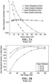
- Figure 2A shows schematically photoelectric absorption and Compton scattering for bones and soft tissues as a function of X photon energy in the range of 30 to 120 keV.
- absorption is very high for the low energy photons and decreases significantly with higher energy.
- the overall mass attenuation coefficient ⁇ l starts being dominated by Compton scattering.
- Figure 2B shows schematically the relative dose delivered to a given patient at different tissue thicknesses as a function of X photon energy to obtain an image within a given acceptable CNR. As can be seen, thicker tissues require photons of higher energy to achieve the best possible dose-to-contrast ratio.
- the photon counting method with or without energy measurement is a technique already used in positron emission tomography (PET) where each annihilation gamma ray photon is timestamped along with an energy measurement to eliminate Compton scattering (Compton scattered photons have less energy). Since the source is monochromatic in PET (511 keV), Compton diffusion can be eliminated by applying an energy threshold. This is not the case in X-ray and CT since the X-ray source has a wide energy spectrum. Moreover, PET systems use large pixels > 0.5 x 0.5 mm 2 , that lead to an insufficient spatial resolution in X-ray CT and a limited count rate.
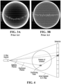
- Cup artefacts as shown in Figure 3 is a well-known problem in CT imaging. This problem occurs because X-rays crossing the central region of the subject have more chance to be absorbed than X-rays passing at the periphery. Similarly, X-rays passing through more tissue have more chance to be subjected to Compton scattering and thus adding noise to the image.
- the cup artefacts can be observed when imaging subjects of different thickness/diameter. At this level, bariatric patients will have more cup artefact than normal patients for identical imaging procedures.
- GR ⁇ TZ MATTHIAS et al. “Time-gated imaging in planar and tomographic x-ray imaging", MEDICAL PHYSICS, AIP, MELVILLE, NY, US, vol. 26, no. 3, 1 March 1999 (1999-03-01), pages 438-446, XP012010731, ISSN: 0094-2405, DOI: 10.1118/1.598535 and MATTHIAS GRATZ et al.: "Time-Gated Imaging in Radiology: Theoretical and Experimental Studies”; IEEE JOURNAL OF SELECTED TOPICS IN QUANTUM ELECTRONICS, IEEE SERVICE CENTER, PISCATAWAY, NJ, US, vol. 2, no.
- GR ⁇ TZ M.et al. in "Time-gated imaging in planar and tomographic x-ray imaging", MEDICAL PHYSICS, vol. 26, no. 3, 1 March, pages 438-446 may be considered to disclose an X-ray imaging apparatus comprising: a pulsed X-ray source having a control signal; a time-sensitive X-ray detector having a time-dependent X-ray photon detection signal output; a processor, the time-sensitive X-ray detector being configured for: providing for each photon detected at each pixel element a time of detection signal; and being responsive to a gate signal controlling a time when photon detection is enabled or disabled; wherein said time-sensitive X-ray detector comprises an X-ray sensitive scintillator and a light sensor array coupled with said scintillator for measuring X-ray detection events in said scintillator; a processor, connected to said control signal and said time-dependent X-ray photon detection signal output, configured to provide a measure of ballistic photons with
- an X-ray imager combines a pulsed X-ray source with a time-sensitive X-ray detector to provide a measure of ballistic photons with a reduction of scattered photons.
- the imager can provide a comparable contrast-to-noise X-ray image using significantly less radiation exposure than conventional X-ray imagers, for example less than about half of the radiation.
- the time resolution of the imaging apparatus is dependent on the sharpness of the rise time of the X-ray source and on the time resolution of the time-sensitive detector. More specifically, if the time resolution is less than about 0.9 nanoseconds, Applicant has found that the contrast to noise ratio (CNR) can be improved over continuous X-ray sources for most human patient imaging. While the rising edge of the X-ray pulse is preferably less than 0.15 nanoseconds, it will be appreciated that improvements in contrast can be achieved with rising edges up to about 0.5 nanoseconds.
- the pulsed X-ray source can have a Gaussian pulse shape with a full width half maximum (FWHM) value in the range of less than 0.1 nanoseconds up to about 0.5 nanoseconds.
- a time point or window parameter can be chosen to accept more or less of the ballistic/scattered photons according to the needs of the acquisition, either to improve the signal-to-noise ratio (SNR) by accepting all ballistic photons or to improve further CNR by cutting part of the ballistic photons to remove more scattered photons.
- SNR signal-to-noise ratio
- the CNR can be at least about doubled for the same dose of radiation when imaging a typical thickness of 20 cm of tissue.
- time resolution better than about 100 picoseconds the amount of radiation delivered to the patient in abdominal imaging can be about 30% or less of the amount of radiation delivered to the patient for continuous, polychromatic X-ray imaging.
- the innovation described herein presents a solution to both the limited count rate and the spatial resolution while significantly reducing the dose.
- the innovation herein described presents a solution to improve the cup artefact problem in bariatric human patients.
- an X-ray imaging apparatus can have a pulsed X-ray source having a control signal that determines the pulse timing and/or the pulse rise time.
- a time-sensitive X-ray detector can be included in the apparatus that has a time-dependent X-ray photon detection signal output.
- a processor that can be connected to the control signal and the time-dependent X-ray photon detection signal output, can be configured to provide a measure of ballistic photons with a reduction of scattered photons received by the time-sensitive detector.
- the pulsed X-ray source may include a high voltage source, electrodes connected to the high voltage source for accelerating electrons, and an X-ray emitting target material arranged to receive the electrons following acceleration by the electrodes so as to produce a pulse of X-rays.
- the pulsed X-ray source may comprise a pulsed laser source responsive to the control signal, a photoelectric material arranged to receive a light pulse from the pulsed laser source and to emit a burst of electrons in response thereto, wherein electrodes are arranged to accelerate the burst of electrons.
- the photoelectric material may be at least a part of a cathode of the electrodes.
- the pulsed X-ray source may comprise deflection electrodes for steering the electrons accelerated by the electrodes connected to the high voltage source to controllably hit the X-ray emitting target material.
- the electrodes connected to the high voltage source comprise a gated carbon nanotube cathode.
- the time-sensitive X-ray detector provides for each photon detected at each pixel element a time of detection signal.
- the time-sensitive X-ray detector is responsive to a gate signal controlling a time when photon detection is enabled.
- the time-sensitive X-ray detector is responsive to a gate signal controlling a time when photon detection is disabled.
- the processor is configured to collect X-ray photons detected within different time frames with respect to the control signal and determine the measure of ballistic photons with a reduction of scattered photons received by the time-sensitive detector through subtraction of the X-ray photons detected within different time frames.
- the time-sensitive X-ray detector is responsive to a pulsed gate signal controlling a time window when photon detection is enabled.
- the time-sensitive X-ray detector is arranged with respect to the pulsed X-ray source so as to provide a different time of flight for the ballistic photons as a function of a pixel location within the time-sensitive X-ray detector, wherein the processor provides the measure of ballistic photons with the reduction of scattered photons received by the time-sensitive detector using different timing as a function of location of the pixels.
- the time-sensitive X-ray detector comprises an X-ray sensitive scintillator and a light sensor array coupled with the scintillator for measuring X-ray detection events in the scintillator.
- the time-sensitive X-ray detector comprises an X-ray sensitive detector based on a direct conversion of photons to electrons for measuring X-ray events in the detector.
- the processor is configured to provide a two-dimensional image.
- the apparatus can further comprise a motorized mounting for moving the pulsed X-ray source and the time-sensitive X-ray detector with respecting to an object or subject to be imaged, wherein the processor is configured to provide a three-dimensional image.
- the apparatus is operative to obtain an image with a given contrast to noise ratio (CNR) while delivering a lower dosage of X-rays to a typical human abdominal region of at least 20 cm thickness than when continuous X-rays of a same energy are used in a similarly-structured continuous X-ray imaging apparatus.
- the lower dosage may be at least 50% lower, preferably at least 60% lower.
- the pulsed X-ray source produces a cone beam and the time-sensitive X-ray detector is arranged to detect a 2D array of pixels.
- a response time of a combination of the pulsed X-ray source and the time-sensitive detector is less than 0.9 nanoseconds.
- the response time is less than 0.3 nanoseconds.
- a rise time of a pulse emitted by said pulsed X-ray source is less than 0.15 nanoseconds.
- the processor is configured to measure an impulse response time of a combination of the pulsed X-ray source and the time-sensitive detector to obtain a measure ballistic photons without an object or patient between the pulsed X-ray source and the time-sensitive detector and to derive therefrom and store in memory a gate parameter for the measure of ballistic photons with a reduction of scattered photons received by the time-sensitive detector when thereafter measuring objects or patients that provide scatter.
- Applicant has also found a method of acquiring a medical diagnostic image of a human patient can comprises using an apparatus as described herein to obtain an image of a region of interest and having a contrast-to-noise ratio using X-rays of a given energy, wherein an amount of radiation delivered to the patient is about 60% or less of an amount of radiation delivered to a same patient for continuous, polychromatic X-ray imaging of the region of interest using the given energy of X-rays.
- the amount of radiation delivered to the patient is about 30% or less of an amount of radiation delivered to a same patient for continuous, polychromatic X-ray imaging of the region of interest using the given energy of X-rays.
- the present invention relates to separating diffused photons from ballistic photons by using photon time-of-flight (elapsed time from emission to detection) measurements.
- photon time-of-flight elapsed time from emission to detection
- X-ray and CT imaging are mainly based on accumulating the energy of X-ray photons into pixels to create a 2D image or a slice of a 3D image. These approaches require a non-negligible dose to extract the useful signal from the background.
- the present invention proposes to measure the time of flight of X photons and directly sort the scattered photons from the ballistic ones. This will allow removing a substantial quantity of photons participating to the background noise of the image, as well as significantly attenuating the cup artefacts present in CT images. A significant dose reduction for a similar contrast can also be obtained, which is critical in several clinical uses of CT.
- the approach to solving the aforementioned problems consists of measuring the time-of-flight (TOF) of each individual photon (or of a burst of photons) to determine whether a photon has followed a straight line ballistic trajectory or has been scattered.
- TOF is defined as the length of time between the photon's emission by the X-ray source and its arrival in the detection system where it is transduced into an electrical signal.
- the distance traveled by a photon is directly related to its TOF since the index of refraction is close to 1 and thus all photons have a speed close to the speed of light in a vacuum.
- Measuring TOF requires knowing when X photons leave the source and when they arrive in the detection system.
- Away to create such a condition can be to use ultra-short pulses of X photons to obtain a precise time of emission, and to measure the time of arrival of each individual photon or of the burst of photons resolved in time.
- improvement in image contrast can be achieved when time resolution is better than about 0.5 nanoseconds, and because a time resolution of at least about 0.2 nanoseconds is feasible using available technology, the improvement in contrast for a given dosage and/or the improvement in the reduction in dosage for a given contrast is significant.
- the detection system decides for each individual photon if the following condition is true: d min c ⁇ ⁇ ⁇ T detection _ T emission ⁇ d max c + W , where T detection is the time of detection, T emission is the time of emission, d max and d min are respectively the maximum and minimum distances from the X-ray source to the detector pixel in which the photon is detected, c is the speed of light in vacuum, W and ⁇ form the limit of the accepted window of time respectively for the late and the early photons. If the previous condition is true, a photon is declared to be ballistic, otherwise it is declared to be scattered.
- the length of the time window (W + ⁇ ) must be chosen according to the spatial uncertainty of the measurements including the time resolution of the detection system, the time jitter of the X-ray source and the needs for the application.
- an acquisition can be made without any subject in the scanner to extract the impulse response of the system which also corresponds to the response of the ballistic photons in a normal measurement.
- the window can be chosen to accept more or less of the ballistic/scattered photon according to the needs of the acquisition, either to improve SNR by accepting all ballistic photons or CNR by cutting part of the ballistic photons to remove more scattered photons. Window optimization will be presented later.
- TOF-X-ray imaging is to remove photons identified as scattered photons from the measurements to reduce scatter noise and its adverse effect on image quality.
- This technique that we call time-of-flight scatter rejection (TSR)
- TSR time-of-flight scatter rejection
- the detection system timestamps and/or counts the photons arriving in each pixel during a period of time in the selected time window. The scattered photons arriving too late (outside the time window) can be discarded from the measurements.
- the temporal X-ray pulse width is preferably as narrow as possible to reduce the dose to the minimum.
- embodiments can operate with longer pulses to the detriment of the injected dose.
- late scattered photons are being discarded by the TSR along with most of the ballistic photon emitted the first few tenths of a picosecond after the pulse.
- the resulting signal is therefore composed mostly of ballistic photons, even though most of them are removed. This allows for CNR improvements at the cost of a higher dose.
- the rising edge of the X-ray pulse must be as sharp as possible to reduce the timing jitter associated to the X-ray source.
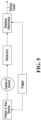
- the required system for TOF- X-ray imaging (whether 2D or 3D) is essentially composed of four parts as shown in Figure 5 : a pulsed X-ray source, a detector, a gated electronic readout system and a synchronisation mechanism or trigger.
- any system able to precisely detect the time of arrival of X photons emitted by a pulsed source synchronized with the detectors' readout electronics could implement TOF-X-ray imaging (whether 2D or 3D).
- TOF-X-ray imaging whether 2D or 3D.
- the system detailed in Figure 6 and Figure 7 could be implemented with a N5084 pulsed X-ray tube from Hamamatsu excited by a Picosecond light pulse PLP-10 from the same company, acting both as a pulsed laser and a trigger.
- the detection system can be implemented using a 500 ⁇ m thick LYSO crystal and a S12571-015C SiPM also from Hamamatsu.
- the readout circuit can be designed as an application specific integrated circuit (ASIC).
- the output of the readout electronics can be subjected to additional digital processing such as finding centroid of events, data sorting and merging, data correction, dark noise filtering, etc.
- the output is TSR pixel data.
- An image processor generates 2D or 3D images from the pixel data using conventional techniques known in the art, however, without needing contrast improvement filters that might be conventionally employed. Such medical images can be viewed at an image viewing workstation as is known in the art.
- the number of scattered photons detected in each pixel is a function of the scattering ability of the object outside of the ballistic photon travel path, those photons can thus be considered as background noise.
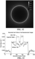
- the reconstructed image including scattered photon shows ( Figure 12 )
- the contribution of those photons to the image is subject to a cup artifact.
- the bone inserts are indistinguishable in this image, thus the scattered photons contribute negatively to the image contrast.
- the CNR is dependent on a statistically viable measurement of ballistic photons above the background. Assuming that the background is not spatially dependent (which it is), contrast is improved by collecting more photons, both ballistic and scattered, so that the spatial variation in ballistic photons provides a better CNR following a background subtraction.
- removing at least a portion of scattered photons using TSR reduces the need for collecting as many photons and improves image quality due to the non-uniform spatial distribution of scattered photons.
- a trigger could be used to generate an ultra-short laser pulse directed onto the photocathode of an X-ray tube, generating a pulse of electrons accelerated in the tube with an electrical field.
- an electron gun or canon could generate a continuous flow of electrons deflected or not on the X-ray emitter target. When the accelerated electrons hit the target then an X-ray pulse is generated towards the volume of interest using an aperture to form a cone shaped beam.
- the X-ray detector converts the photons into electric pulses.
- the detector is composed of a material with good X photon stopping power and able to generate low jitter electric pulses.
- the detector could be of any material for which the combination scintillating crystal/digital silicon photomultiplier is a good candidate, or alternatively a direct X-photon detector that can be gated with the desired time sensitivity.
- a brute force approach for the trigger could be an implementation where all detector pixels can individually timestamp the time of arrival of each individual X photon ( Figure 7 ).
- a digital signal processor can then sort and compute the data to extract the relevant information.
- Another approach would be to electronically open a programmable or fixed time window directly within the detector.
- a trigger sent through a programmable or fixed delay line to the readout electronics of each pixel will initiate the acquisition.
- the timing window can then be adjusted to count only ballistic photons and remove the scattered photons ( Figure 6 ).
- the photon count in each pixel is finally sent to a centralized unit performing, if needed, additional digital signal processing before sending the data to a computer to perform image reconstruction in the case of computed tomography or to perform any desired image processing in the case of a 2D image.
- the Monte Carlo simulator GATE was used to simulate a cone-beam CT scanner with a flat panel detector system.
- a point source emits a continuous monochromatic beam of photons in an isotropic circular cone pattern towards a square flat panel array of detectors.
- the window was always placed within three standard deviations (3 ⁇ ) of the total timing resolution (assumed to be Gaussian), to keep at least 99.5% of transmitted photons.
- the source emits a 120 keV cone of X photons with an 8°angle.
- the phantom was placed 102 cm away from the source and a 256 x 256 array of 1 x 1 mm 2 pixels detector was placed 63 cm behind the phantom.
- the scattered to primary radiation ratio is the energy of the scattered radiation (S) divided by the energy of the primary beam (P) striking the same point on the imaging device).
- SPR The scattered to primary radiation ratio
- SPR after applying TSR for increasing initial SPR obtained with 50, 100, 150 and 200 mm thick phantoms is presented in Figure 8 .
- TSR time resolution
- improvements can be seen in some systems with both high incident photon energy and large source-to-detector distance.
- improving total timing resolution below 10 ps does not lead to significantly better results.
- the achieved SPR worsens with lower energies and smaller source-to-detector distance as seen in Figures 9A and 9B respectively.
- FIG. 11A and Figure 11B A slice of a reconstructed image of a 288 mm wide water cylinder with two bone inserts before and after applying TSR is shown in Figure 11A and Figure 11B respectively.
- the image was normalized then reconstructed by feeding the sinogram directly to the Reconstruction Toolkit (RTK) Feldkamp, Davis and Kress algorithm (FDK) with no additional processing.
- RTK Reconstruction Toolkit
- FDK Davis and Kress algorithm
- SPR decreased from 300% to about 4% at the center of the detection system.
- the bone inserts are indistinguishable in the removed scattered photons image ( Figure 12 ) and a cup artifact is present. This explains the increase of contrast once those photons are removed from the reconstruction data.
- the expected dosage reduction as a function of SPR reduction is shown in Figure 10 .
- the degradation of CNR can be corrected with either an increase of dose or an increase in pixel size, shown in Figure 10 as a z , however such increase also reduces spatial resolution. Therefore, to correct for a scatter noise of 100% SPR and keep the same spatial resolution, a four-fold increase in dose is required. If the total time resolution is short enough to completely mitigate the effect of scatter noise, it could be possible to divide the dose by four. With a time resolution of around 100 ps, the expected dose reduction for an abdomen scan is more than 50%.
- the most probable value (MPV) of the TOF with the beam blocker is 390 ps later than the MPV without the beam blocker, which correspond to an increase of travel path of about 12 cm. This fits with the expected increase of travel path needed to circle the beam blocker by scattering on the X-ray enclosure. No TOF correction was made for the energy of the detected photons. Higher energy photons were detected earlier, however, the increased TOF of scattered photons is observed at all energy levels at around 400 ps. Dark counts and double detections were removed from both measurements.
- the X-ray source is responsible for emitting X-rays.
- the first X-ray sources were vacuum tubes (so-called X-ray tubes). It is with such devices that Roentgen accidentally discovered X-rays. Their construction is rather simple as illustrated schematically in Figure 15 .
- a vacuum tube At one end of a vacuum tube is a filament heated at high temperature by an electric current (voltage Uh). Through the physical process of thermionic emission, electrons are ejected from the filament (so-called the hot cathode, made out of metal, typically tungsten).
- the hot cathode made out of metal, typically tungsten
- At the other end of the tube is a little plate (the anode also often made of tungsten) onto which the electrons are directed.
- a high voltage (Ua) electric field is established between the cathode and the anode for accelerating the electrons from the cathode to the anode.
- the electrons impinge onto the anode they are rapidly decelerated as they slowdown in the metal and X-ray photons are emitted through the process of Bremsstrahlung (from the German literally meaning braking radiation).
- X-ray photons are emitted through the process of Bremsstrahlung (from the German literally meaning braking radiation).
- X-ray photons are emitted through the process of Bremsstrahlung (from the German literally meaning braking radiation).
- the emitted X photons have energies that span a given range, so-called the energy spectrum of the source.
- a source that emits X photons of only one energy is called monochromatic, otherwise it is called polychromatic (this terminology is in analogy with visible photons for which different energies correspond to different colors - chroma)
- Another means for producing X-rays is by bending radially a beam of electrons, i.e. when the electrons accelerate perpendicular to their velocity. This occurs for instance in synchrotrons using bending magnets.
- the radiation is called cyclotron (resp. synchrotron) radiation. Because of the great control of acceleration in synchrotrons, these are able to produce highly monochromatic X-rays.
- synchrotrons and cyclotrons are large infrastructures that are not viable for integration in commercial medical imaging devices.
- an ultra-short high intensity laser pulse is focused onto a metallic target which rips out electrons from the metal and accelerates the electrons back towards the metal target where they decelerate, thus producing short X-ray bursts.
- Another approach is through high-order harmonic generation in gases, which resorts to intense ultra-short laser pulses. This approach can be carried out in gas-filled hollow fibers (Von Der Linde et al. 2001). These approaches can be foreseen to be amenable to reasonable sizes for integration in medical imaging devices since ultra-short pulse laser technology is nowadays highly compact.
- Yet another approach to generate short X-ray pulses is to use an X-ray tube in which the electron beam can be very rapidly deflected as in a streak camera, with an electric pulsed field in such a way that it strikes the anode for a very short time interval in which bremsstrahlung X-rays can be generated.
- CNT carbon nanotubes
- the detector is among the important components to consider in the deployment of the technology.
- the electron/hole mobility in direct conversion detectors coupled to the detector thickness do not currently allow obtaining timing performance in the tens of picoseconds as can be desired.
- a thin scintillator able to stop an X photon coupled to a high-speed photodetector such as a silicon photomultiplier (SiPM) or all its digital derivatives is a good candidate for a complete system with timing performance under 100 ps.
- an adjustable and delayed trigger can be distributed in the scanner.
- This trigger can open a time window where all photons striking the detector in the time window are timestamped or counted.
- the information can still be sent to a local or a remote digital processor with the goal to extract the relevant information to be fed to the image reconstruction algorithm.
- the trigger can be self-adjusted from the center of the detector panel to the periphery or manually adjusted with programmable or fixed delay lines to take into account the source to flat panel distance variation form the center to the periphery. In the former case, each pixel has a communication link with its adjacent neighbor while in the latter case, a system calibration is mandatory.
- Optimizing TOF- X-ray imaging revolves around one central idea: having the right gate width.
- the gate width is selected to be narrow enough to allow almost all the ballistic photons but remove the maximum number of scattered photons. To achieve this, the impact of every component of the system on the gate width must be considered.
- the gate width would be almost zero, but the source pulse width must then be short enough to avoid removing ballistic photons. Parameters leading to errors in TOF measurements, such as the pulse width of the X-ray source (and in some cases the sharpness of the rising edge of the pulse) or the timing resolution of the detectors, widen the response of the system to ballistic photons.
- the gate must be widened even if the errors increase, but doing this reduces the proportion of scattered photons being removed.
- the gate width can be chosen more conservatively or more aggressively according to whether SNR or CNR is driving the dose.
- increasing the SNR is particularly important in very low dose applications and in imaging systems with a naturally high contrast such as inorganic imaging.
- CNR will drive the dose up in biological tissue imaging with only small density differences such as in breast imaging.
- Reducing the total time resolution is one of the most important design aspects of TOF-X-ray imaging (whether 2D or 3D).
- the errors caused by each component of the system are added together in quadrature.
- reducing the pulse width and the timing resolution of the detectors is equally important to increase the efficiency of discrimination. If both effects are reduced to under 10 ps, the spatial uncertainty of the emission (the size of the focal spot of the source) and of the detection (size of the detector and error on positioning) will also have to be optimized since this affects the expected TOF for ballistic photons used as a comparison for the discrimination. Jitter between detectors will also increase the error on the measurements and will have to be reduced to a minimum.
- the present method uses the maximum possible TOF between the source and a pixel for discriminating ballistic and scattered X photons. However, to further optimize this method, it could be useful, in large pixel-size systems, to use the most likely depth of detection for the window. Doing this will reduce the number of ballistic photons that are retained, but should reduce the measured SPR.
- Embodiments can be implemented in a variety of systems. The following have been identified as potential interesting applications of TOF- X-ray imaging (whether 2D or 3D):
- the window can be modified according to the required needs, for instance looking for fractured bones requires a large window to increase SNR, but scanning the same area for potential tumors requires a small window to increase CNR.
- Spatial resolution is particularly important for both pre-clinical and interventional radiology.
- a significantly higher spatial resolution can be obtained by using embodiments as described herein in conjunction with single photon avalanche diodes (SPADs) detectors to precisely pinpoint the location of the interaction of the X-ray with the detectors.
- the quality of the discrimination, along with the spatial resolution, can also be improved by using a magnification process such as increasing the distance between the volume of interest and the detector system.
- Scanning bariatric patients requires photons of higher energies than the standard range of energy used in X-ray imaging (whether 2D or 3D) and yields a lower contrast image.
- TSR is particularly useful for scanning bariatric patients since larger volumes generate more scatter noise that is easier to remove with our approach since the photons generally scatter more than once in the subject in those cases.
- Optimizing for contrast notably by choosing an aggressive gate, smaller than the total time resolution of the system, could even further help to scan bariatric patients.
- Cone-beam CT has a big advantage over standard helicoidal fan beam CT mostly used nowadays since it does not require linear translation of the patient.
- the simplicity of the mechanical parts of cone-beam CT reduces the form factor of the scanner, a necessity to use such system directly in an operating theater.
- embodiments of the invention can be well suited for gated imaging where the X-ray source could be turned on and off according to an external signal such as respiratory gating or cardiac to avoid motion artifacts and better visualise the organ. CNR could then be better improved in such circumstances.
Landscapes
- Health & Medical Sciences (AREA)
- Life Sciences & Earth Sciences (AREA)
- Engineering & Computer Science (AREA)
- Medical Informatics (AREA)
- Physics & Mathematics (AREA)
- Molecular Biology (AREA)
- High Energy & Nuclear Physics (AREA)
- Heart & Thoracic Surgery (AREA)
- General Health & Medical Sciences (AREA)
- Pathology (AREA)
- Radiology & Medical Imaging (AREA)
- Biomedical Technology (AREA)
- Nuclear Medicine, Radiotherapy & Molecular Imaging (AREA)
- Biophysics (AREA)
- Surgery (AREA)
- Animal Behavior & Ethology (AREA)
- Optics & Photonics (AREA)
- Public Health (AREA)
- Veterinary Medicine (AREA)
- General Physics & Mathematics (AREA)
- Spectroscopy & Molecular Physics (AREA)
- Computer Vision & Pattern Recognition (AREA)
- Toxicology (AREA)
- Mathematical Physics (AREA)
- Pulmonology (AREA)
- Theoretical Computer Science (AREA)
- Apparatus For Radiation Diagnosis (AREA)
Claims (13)
- Appareil d'imagerie à rayons X comprenant :une source de rayons X pulsée ayant un signal de commande, dans lequel ladite source de rayons X pulsée produit un faisceau en forme de cône ;un détecteur de rayons X sensible au temps ayant une sortie de signal de détection de photons de rayons X dépendant du temps, le détecteur de rayons X sensible au temps étant configuré pour une des opérations suivantes :fournir pour chaque photon détecté à chaque élément de pixel un signal de détection de temps ; etréagir à un signal de grille commandant le moment où la détection de photons est activée ou désactivée ;dans lequel ledit détecteur de rayons X sensible au temps comprend un scintillateur sensible aux rayons X et un réseau de capteurs de lumière couplé audit scintillateur pour mesurer les événements de détection de rayons X dans ledit scintillateur ;un processeur, connecté audit signal de commande et audit sortie de signal de détection de photons de rayons X dépendant du temps, configuré pour fournir une mesure de photons balistiques avec une réduction dans la mesure de photons diffusés reçus par ledit détecteur sensible au temps ;dans lequel ledit détecteur de rayons X sensible au temps est disposé par rapport à ladite source de rayons X pulsée de manière à fournir un temps de vol différent pour lesdits photons balistiques en fonction de l'emplacement de pixel dans ledit détecteur de rayons X sensible au temps ; etdans lequel ledit processeur fournit ladite mesure de photons balistiques avec ladite réduction dans la mesure de photons diffusés reçus par ledit détecteur sensible au temps en utilisant un temps différent en fonction de l'emplacement desdits pixels.
- Appareil tel que défini dans la revendication 1, dans lequel ladite source de rayons X pulsée comprend une source de haute tension, des électrodes connectées à ladite source de haute tension pour accélérer les électrons, et un matériau cible émettant des rayons X arrangé pour recevoir lesdits électrons après accélération par lesdites électrodes de manière à produire une impulsion de rayons X.
- Appareil tel que défini dans la revendication 2, dans lequel ladite source de rayons X pulsée comprend :une source laser pulsée réagissant audit signal de commande ;un matériau photoélectrique pour recevoir une impulsion lumineuse de ladite source laser pulsée et pour émettre une salve d'électrons en réponse à celle-ci ;dans lequel les électrodes sont disposées de manière à accélérer ladite salve d'électrons.
- Appareil tel que défini dans la revendication 3, dans lequel ledit matériau photoélectrique est au moins une partie d'une cathode desdites électrodes.
- Appareil tel que défini dans la revendication 2, dans lequel ladite source de rayons X pulsée comprend des électrodes de déviation pour diriger lesdits électrons accélérés par lesdits électrodes connectées à ladite source de haute tension afin d'atteindre de manière contrôlée ledit matériau cible émettant des rayons X.
- Appareil tel que défini dans la revendication 2, dans lequel lesdites électrodes connectées à ladite source de haute tension comprennent une cathode à nanotubes de carbone à grille.
- Appareil tel que défini dans l'une quelconque des revendications 1 à 6, dans lequel ledit processeur est configuré pour fournir une image bidimensionnelle.
- Appareil défini dans l'une quelconque des revendications 1 à 7, comprenant en outre un support motorisé pour déplacer ladite source de rayons X pulsée et ledit détecteur de rayons X sensible au temps par rapport à un objet ou à un sujet à imager, dans lequel ledit processeur est configuré pour fournir une image tridimensionnelle.
- Appareil défini dans l'une quelconque des revendications 1 à 8, dans lequel ledit appareil est opérationnel pour obtenir une image avec un rapport contraste sur bruit donné (CNR) tout en délivrant un dosage de rayons X à une région abdominale humaine typique d'au moins 20 cm d'épaisseur qui est au moins 50 % inférieure à celle obtenue lorsque ledit détecteur de rayons X sensible au temps et ledit processeur sont configurés pour mesurer à la fois les photons balistiques et les photons diffusés sans réduction dans la mesure de photons diffusés provenant de ladite source de rayons X pulsée.
- Appareil tel que défini dans la revendication 9, dans lequel ledit dosage est inférieur d'au moins 60 %.
- Appareil défini dans l'une quelconque des revendications 1 à 10, dans lequel le temps de montée d'une impulsion émise par ladite source de rayons X pulsée est inférieur à 0,15 nanoseconde, et le temps de réponse d'une combinaison de ladite source de rayons X pulsée et dudit détecteur sensible au temps est inférieur à 0,9 nanoseconde, de préférence inférieur à 0,3 nanoseconde.
- Appareil tel que défini dans l'une quelconque des revendications 1 à 11, dans lequel ledit processeur est configuré pour mesurer un temps de réponse impulsionnel d'une combinaison de ladite source de rayons X pulsée et dudit détecteur sensible au temps afin d'obtenir une mesure de photons balistiques sans objet ou patient entre ladite source de rayons X pulsée et ledit détecteur sensible au temps et pour en déduire et stocker dans la mémoire un paramètre de grille pour ladite mesure de photons balistiques avec une réduction dans la mesure de photons diffusés reçus par ledit détecteur sensible au temps lors de la mesure ultérieure d'objets ou de patients qui produisent de la diffusion.
- Procédé d'acquisition d'une image de diagnostic médical d'un patient humain comprenant l'utilisation d'un appareil tel que défini dans l'une quelconque des revendications 1 à 12 pour obtenir une image d'une région d'intérêt ayant un rapport contraste sur bruit en utilisant des rayons X d'une énergie donnée, dans lequel une quantité de rayonnement délivrée audit patient est d'environ 60 % ou moins, et de préférence d'environ 30 % ou moins, d'une quantité de rayonnement délivrée à un même patient pour une imagerie à rayons X polychromatique continue de ladite région d'intérêt en utilisant ladite énergie donnée de rayons X.
Applications Claiming Priority (2)
| Application Number | Priority Date | Filing Date | Title |
|---|---|---|---|
| US201862755813P | 2018-11-05 | 2018-11-05 | |
| PCT/CA2019/051521 WO2020093140A1 (fr) | 2018-11-05 | 2019-10-29 | Imagerie par rayons x pulsée |
Publications (4)
| Publication Number | Publication Date |
|---|---|
| EP3871014A1 EP3871014A1 (fr) | 2021-09-01 |
| EP3871014A4 EP3871014A4 (fr) | 2021-12-01 |
| EP3871014C0 EP3871014C0 (fr) | 2023-11-29 |
| EP3871014B1 true EP3871014B1 (fr) | 2023-11-29 |
Family
ID=70611113
Family Applications (1)
| Application Number | Title | Priority Date | Filing Date |
|---|---|---|---|
| EP19882323.9A Active EP3871014B1 (fr) | 2018-11-05 | 2019-10-29 | Imagerie par rayons x pulsée |
Country Status (5)
| Country | Link |
|---|---|
| US (1) | US11872068B2 (fr) |
| EP (1) | EP3871014B1 (fr) |
| JP (1) | JP7427664B2 (fr) |
| CA (1) | CA3118709A1 (fr) |
| WO (1) | WO2020093140A1 (fr) |
Families Citing this family (1)
| Publication number | Priority date | Publication date | Assignee | Title |
|---|---|---|---|---|
| CN113456094B (zh) * | 2021-07-02 | 2023-11-21 | 戴建荣 | 一种时间同步方式采集端口图像方法 |
Family Cites Families (17)
| Publication number | Priority date | Publication date | Assignee | Title |
|---|---|---|---|---|
| US5519227A (en) * | 1994-08-08 | 1996-05-21 | The University Of Massachusetts Medical Center | Structured scintillation screens |
| US5999836A (en) * | 1995-06-06 | 1999-12-07 | Nelson; Robert S. | Enhanced high resolution breast imaging device and method utilizing non-ionizing radiation of narrow spectral bandwidth |
| JP2000187077A (ja) | 1998-12-24 | 2000-07-04 | Japan Atom Energy Res Inst | 2次元放射線イメージ検出装置及びその検出方法 |
| US6687333B2 (en) * | 1999-01-25 | 2004-02-03 | Vanderbilt University | System and method for producing pulsed monochromatic X-rays |
| WO2001019143A1 (fr) | 1999-09-09 | 2001-03-15 | The Government Of The United States Of America, As Represented By The Secretary, Department Of Health & Human Services, The National Institutes Of Health | Imagerie a selection temporelle avec source a faisceau divise |
| JP2001155897A (ja) | 1999-11-25 | 2001-06-08 | Japan Atom Energy Res Inst | 短パルス硬x線発生装置 |
| JP4202906B2 (ja) | 2003-12-25 | 2008-12-24 | 株式会社東芝 | X線コンピュータ断層撮影装置 |
| CN101080653B (zh) * | 2004-12-17 | 2012-02-29 | 皇家飞利浦电子股份有限公司 | 一种x射线照相成像设备、方法及x射线断层摄影扫描器 |
| US7796726B1 (en) * | 2006-02-14 | 2010-09-14 | University Of Maryland, Baltimore County | Instrument and method for X-ray diffraction, fluorescence, and crystal texture analysis without sample preparation |
| WO2009007902A2 (fr) | 2007-07-11 | 2009-01-15 | Philips Intellectual Property & Standards Gmbh | Source de rayons x pour une mesure de rayonnement |
| WO2009012453A1 (fr) * | 2007-07-19 | 2009-01-22 | The University Of North Carolina At Chapel Hill | Systèmes de tomosynthèse numérique du sein aux rayons x stationnaires et procédés apparentés |
| CN104603600B (zh) | 2012-07-01 | 2017-09-01 | 卢米托股份有限公司 | 用于散射介质中改进的扩散发光成像或者断层照相的系统和方法 |
| GB2513408B (en) | 2013-04-26 | 2017-12-13 | Toshiba Res Europe Limited | A photon detector and a photon detection method |
| US10107768B2 (en) * | 2013-08-13 | 2018-10-23 | Duke University | Volumetric-molecular-imaging system and method therefor |
| DK3139837T3 (da) | 2014-05-08 | 2020-09-28 | L Livermore Nat Security Llc | Fremgangsmåder til 2-farvet radiografi med laser-compton-røntgenkilder |
| US20170219501A1 (en) | 2016-01-28 | 2017-08-03 | The Research Foundation For The State University Of New York | Methods and systems for time-of-flight x-ray tomography |
| US10134571B1 (en) * | 2018-01-26 | 2018-11-20 | C-Rad Imaging Ab | Detector for incident radiation |
-
2019
- 2019-10-29 WO PCT/CA2019/051521 patent/WO2020093140A1/fr unknown
- 2019-10-29 CA CA3118709A patent/CA3118709A1/fr active Pending
- 2019-10-29 JP JP2021523961A patent/JP7427664B2/ja active Active
- 2019-10-29 US US17/290,815 patent/US11872068B2/en active Active
- 2019-10-29 EP EP19882323.9A patent/EP3871014B1/fr active Active
Also Published As
| Publication number | Publication date |
|---|---|
| EP3871014C0 (fr) | 2023-11-29 |
| US11872068B2 (en) | 2024-01-16 |
| WO2020093140A1 (fr) | 2020-05-14 |
| EP3871014A1 (fr) | 2021-09-01 |
| JP2022520143A (ja) | 2022-03-29 |
| US20210369222A1 (en) | 2021-12-02 |
| EP3871014A4 (fr) | 2021-12-01 |
| CA3118709A1 (fr) | 2020-05-14 |
| JP7427664B2 (ja) | 2024-02-05 |
Similar Documents
| Publication | Publication Date | Title |
|---|---|---|
| US7039153B2 (en) | Imaging tomography device with at least two beam detector systems, and method to operate such a tomography device | |
| US7813474B2 (en) | Method and apparatus for performing dual-spectrum CT with fast KV modulation at multiple-view intervals | |
| EP1982164B1 (fr) | Appareil de prise d'images utilisant des sources de rayons x reparties et son procede d'utilisation | |
| JP6118429B2 (ja) | 適合されたエネルギー閾値を用いてエネルギー分解x線画像を生成するための方法及びデバイス、当該方法を実施するプログラム、当該プログラムが記憶されているコンピュータ可読媒体 | |
| US10481113B2 (en) | X-ray backscatter inspection system | |
| US8483352B2 (en) | Stacked x-ray detector assembly and method of making same | |
| US20160220207A1 (en) | Panoramic imaging using multi-spectral x-ray source | |
| US10827992B2 (en) | Energy-discriminating photon-counting detector and the use thereof | |
| NL1034576C2 (nl) | Afzonderlijke detectie van invallende energiespectra. | |
| US8712138B2 (en) | Device and method for generating soft tissue contrast images | |
| Berger et al. | X-ray Imaging | |
| JP5779819B2 (ja) | 放射線検出器 | |
| EP1996077B1 (fr) | Detection par balayage double source de rayonnement ionisant | |
| EP3139837B1 (fr) | Procédés de radiographie à 2 couleurs à l'aide de sources de rayons x à compton laser | |
| EP3871014B1 (fr) | Imagerie par rayons x pulsée | |
| US20150123003A1 (en) | High resolution absorption imaging using annihilation radiation from an external positron source | |
| JP7019286B2 (ja) | データ収集装置及びx線ct装置 | |
| AU2004293737A1 (en) | Examination method and apparatus | |
| JP2000189409A (ja) | 放射線画像信号検出装置 | |
| WO2024092370A1 (fr) | Imagerie par rayons x à temps de vol améliorée utilisant une fonction d'étalement de points temporels (tpsf) | |
| Dydula | Development of x-ray coherent scatter projection imaging systems | |
| Rosentreter | X-ray fluorescence imaging: experimental and numerical analysis of a crystal based concept | |
| Yanoff et al. | Quantum x-ray imaging for medical and industrial applications | |
| JP2023027440A (ja) | X線診断装置およびトモシンセシス画像生成方法 | |
| Baldazzi et al. | Investigation of spectral stability of X-ray tubes by simulations and experimental spectrum measurements |
Legal Events
| Date | Code | Title | Description |
|---|---|---|---|
| STAA | Information on the status of an ep patent application or granted ep patent |
Free format text: STATUS: THE INTERNATIONAL PUBLICATION HAS BEEN MADE |
|
| PUAI | Public reference made under article 153(3) epc to a published international application that has entered the european phase |
Free format text: ORIGINAL CODE: 0009012 |
|
| STAA | Information on the status of an ep patent application or granted ep patent |
Free format text: STATUS: REQUEST FOR EXAMINATION WAS MADE |
|
| 17P | Request for examination filed |
Effective date: 20210526 |
|
| AK | Designated contracting states |
Kind code of ref document: A1 Designated state(s): AL AT BE BG CH CY CZ DE DK EE ES FI FR GB GR HR HU IE IS IT LI LT LU LV MC MK MT NL NO PL PT RO RS SE SI SK SM TR |
|
| A4 | Supplementary search report drawn up and despatched |
Effective date: 20211102 |
|
| RIC1 | Information provided on ipc code assigned before grant |
Ipc: H05G 1/08 20060101ALI20211026BHEP Ipc: H01J 35/06 20060101ALI20211026BHEP Ipc: G01T 1/17 20060101ALI20211026BHEP Ipc: A61B 6/00 20060101ALI20211026BHEP Ipc: H05G 1/62 20060101ALI20211026BHEP Ipc: G01N 23/04 20180101ALI20211026BHEP Ipc: A61B 6/03 20060101ALI20211026BHEP Ipc: G01T 1/29 20060101AFI20211026BHEP |
|
| DAV | Request for validation of the european patent (deleted) | ||
| DAX | Request for extension of the european patent (deleted) | ||
| RIC1 | Information provided on ipc code assigned before grant |
Ipc: H05G 1/08 20060101ALI20230512BHEP Ipc: H01J 35/06 20060101ALI20230512BHEP Ipc: G01T 1/17 20060101ALI20230512BHEP Ipc: A61B 6/03 20060101ALI20230512BHEP Ipc: A61B 6/00 20060101ALI20230512BHEP Ipc: G01T 1/29 20060101AFI20230512BHEP |
|
| GRAP | Despatch of communication of intention to grant a patent |
Free format text: ORIGINAL CODE: EPIDOSNIGR1 |
|
| STAA | Information on the status of an ep patent application or granted ep patent |
Free format text: STATUS: GRANT OF PATENT IS INTENDED |
|
| INTG | Intention to grant announced |
Effective date: 20230623 |
|
| GRAS | Grant fee paid |
Free format text: ORIGINAL CODE: EPIDOSNIGR3 |
|
| GRAA | (expected) grant |
Free format text: ORIGINAL CODE: 0009210 |
|
| STAA | Information on the status of an ep patent application or granted ep patent |
Free format text: STATUS: THE PATENT HAS BEEN GRANTED |
|
| AK | Designated contracting states |
Kind code of ref document: B1 Designated state(s): AL AT BE BG CH CY CZ DE DK EE ES FI FR GB GR HR HU IE IS IT LI LT LU LV MC MK MT NL NO PL PT RO RS SE SI SK SM TR |
|
| REG | Reference to a national code |
Ref country code: GB Ref legal event code: FG4D |
|
| REG | Reference to a national code |
Ref country code: CH Ref legal event code: EP |
|
| REG | Reference to a national code |
Ref country code: DE Ref legal event code: R096 Ref document number: 602019042593 Country of ref document: DE |
|
| REG | Reference to a national code |
Ref country code: IE Ref legal event code: FG4D |
|
| U01 | Request for unitary effect filed |
Effective date: 20231222 |
|
| U07 | Unitary effect registered |
Designated state(s): AT BE BG DE DK EE FI FR IT LT LU LV MT NL PT SE SI Effective date: 20240109 |
|
| PG25 | Lapsed in a contracting state [announced via postgrant information from national office to epo] |
Ref country code: GR Free format text: LAPSE BECAUSE OF FAILURE TO SUBMIT A TRANSLATION OF THE DESCRIPTION OR TO PAY THE FEE WITHIN THE PRESCRIBED TIME-LIMIT Effective date: 20240301 |
|
| PG25 | Lapsed in a contracting state [announced via postgrant information from national office to epo] |
Ref country code: IS Free format text: LAPSE BECAUSE OF FAILURE TO SUBMIT A TRANSLATION OF THE DESCRIPTION OR TO PAY THE FEE WITHIN THE PRESCRIBED TIME-LIMIT Effective date: 20240329 |
|
| PG25 | Lapsed in a contracting state [announced via postgrant information from national office to epo] |
Ref country code: ES Free format text: LAPSE BECAUSE OF FAILURE TO SUBMIT A TRANSLATION OF THE DESCRIPTION OR TO PAY THE FEE WITHIN THE PRESCRIBED TIME-LIMIT Effective date: 20231129 |
|
| PG25 | Lapsed in a contracting state [announced via postgrant information from national office to epo] |
Ref country code: IS Free format text: LAPSE BECAUSE OF FAILURE TO SUBMIT A TRANSLATION OF THE DESCRIPTION OR TO PAY THE FEE WITHIN THE PRESCRIBED TIME-LIMIT Effective date: 20240329 Ref country code: GR Free format text: LAPSE BECAUSE OF FAILURE TO SUBMIT A TRANSLATION OF THE DESCRIPTION OR TO PAY THE FEE WITHIN THE PRESCRIBED TIME-LIMIT Effective date: 20240301 Ref country code: ES Free format text: LAPSE BECAUSE OF FAILURE TO SUBMIT A TRANSLATION OF THE DESCRIPTION OR TO PAY THE FEE WITHIN THE PRESCRIBED TIME-LIMIT Effective date: 20231129 |