EP3870525B1 - Flüssigkeitsstabilisierende einlage für einen tankcontainer, herstellungsverfahren einer einlage und herstellungsverfahren eines tankcontainers - Google Patents
Flüssigkeitsstabilisierende einlage für einen tankcontainer, herstellungsverfahren einer einlage und herstellungsverfahren eines tankcontainers Download PDFInfo
- Publication number
- EP3870525B1 EP3870525B1 EP19828893.8A EP19828893A EP3870525B1 EP 3870525 B1 EP3870525 B1 EP 3870525B1 EP 19828893 A EP19828893 A EP 19828893A EP 3870525 B1 EP3870525 B1 EP 3870525B1
- Authority
- EP
- European Patent Office
- Prior art keywords
- inliner
- liquid
- inflatable unit
- stabilizing
- wall
- Prior art date
- Legal status (The legal status is an assumption and is not a legal conclusion. Google has not performed a legal analysis and makes no representation as to the accuracy of the status listed.)
- Active
Links
Images

Classifications
-
- B—PERFORMING OPERATIONS; TRANSPORTING
- B65—CONVEYING; PACKING; STORING; HANDLING THIN OR FILAMENTARY MATERIAL
- B65D—CONTAINERS FOR STORAGE OR TRANSPORT OF ARTICLES OR MATERIALS, e.g. BAGS, BARRELS, BOTTLES, BOXES, CANS, CARTONS, CRATES, DRUMS, JARS, TANKS, HOPPERS, FORWARDING CONTAINERS; ACCESSORIES, CLOSURES, OR FITTINGS THEREFOR; PACKAGING ELEMENTS; PACKAGES
- B65D90/00—Component parts, details or accessories for large containers
- B65D90/02—Wall construction
- B65D90/04—Linings
- B65D90/046—Flexible liners, e.g. loosely positioned in the container
-
- B—PERFORMING OPERATIONS; TRANSPORTING
- B65—CONVEYING; PACKING; STORING; HANDLING THIN OR FILAMENTARY MATERIAL
- B65D—CONTAINERS FOR STORAGE OR TRANSPORT OF ARTICLES OR MATERIALS, e.g. BAGS, BARRELS, BOTTLES, BOXES, CANS, CARTONS, CRATES, DRUMS, JARS, TANKS, HOPPERS, FORWARDING CONTAINERS; ACCESSORIES, CLOSURES, OR FITTINGS THEREFOR; PACKAGING ELEMENTS; PACKAGES
- B65D90/00—Component parts, details or accessories for large containers
- B65D90/52—Anti-slosh devices
-
- B—PERFORMING OPERATIONS; TRANSPORTING
- B65—CONVEYING; PACKING; STORING; HANDLING THIN OR FILAMENTARY MATERIAL
- B65D—CONTAINERS FOR STORAGE OR TRANSPORT OF ARTICLES OR MATERIALS, e.g. BAGS, BARRELS, BOTTLES, BOXES, CANS, CARTONS, CRATES, DRUMS, JARS, TANKS, HOPPERS, FORWARDING CONTAINERS; ACCESSORIES, CLOSURES, OR FITTINGS THEREFOR; PACKAGING ELEMENTS; PACKAGES
- B65D2590/00—Component parts, details or accessories for large containers
- B65D2590/02—Wall construction
- B65D2590/04—Linings
- B65D2590/043—Flexible liners
- B65D2590/046—Bladders
Definitions
- the invention relates to a liquid-stabilizing inliner for use in a tank container, to a method for preparing such inliner, to an assembly of such liquid-stabilizing inliner and a tank container, and to a method for preparing such assembly.
- containers wherein such liquids temporarily reside, and which have dimensions that allow them to be transported by trucks, trains and (container)ships.
- Such containers are usually filled and emptied via a drain hole that is present at or near their bottom. Other holes may also provide access to the inside of the container, such as a manhole or a venting hole.
- a particular type of container for transporting liquids is a so-called tank container. These containers are among the largest containers for this purpose. Their volume usually ranges from 10,000 m 3 to 50,000 m 3 . They have a typical content of about 25,000 m 3 , and are shaped in a more or less cylindrical form.
- an inliner may be used inside the container, so that the container does not have to be cleaned after use. Instead, the inliner is then simply removed from the container, after which the container is ready for re-use.
- a further advantage of such inliner is that it protects the liquid in the container against contamination, decay and spoilage.
- Inliner-technology for the transport or storage of liquids in a container is also described in e.g. JPH03256887A , US2016/355332A1 , US6726052B1 , US2007/095423A1 and WO2011/159265A1 .
- the present invention relates to a liquid-stabilizing inliner for use in a tank container, comprising an inliner having an inliner wall made of a film material, wherein the inliner wall
- a liquid-stabilizing inliner of the invention is formed by an inliner and an inflatable unit that is connected to the inliner.
- the inliner may in principle be any inliner that is suitable for use in a tank container.
- Such inliner is in fact a bag that is formed by an inliner wall.
- the inside of the bag is the interior space wherein a liquid can be stored and/or contained. Outside the bag is the exterior environment.
- the inliner wall has an inner surface that faces the interior space and an outer surface that faces the exterior environment.
- the inliner wall is made of a film material. Such material is flexible so that the inliner can be in a folded state when empty, and is capable of unfolding during filling of the inliner with a liquid so that it can adopt the shape of the tank container.
- the actual volume of the interior space depends on the shape of the inliner wall.
- the inliner wall will change its shape so as to enclose an increased volume, thereby increasing the volume of the interior space.
- Suitable film materials for the inliner wall are known in the art. For example, such material is layered and so comprises a plurality of layers that have been glued together. Usually, the material comprises at least one barrier layer that is impenetrable to air and/or water.
- the inliner wall thus separates the interior space from the exterior environment.
- the inliner in principle completely encloses the interior space.
- the inliner wall (and thus also the inliner itself) however comprises an opening to allow the passage of liquid, so that the inliner can be filled with a liquid.
- Such opening also allows the discharge of liquid from the inliner.
- an opening in the inliner wall is capable of being closed, e.g. with a cap or stopper, so that the interior space can be completely shut off from the exterior environment.
- the opening comprises a spout (e.g. it merges into a spout) that can act as a receiver for such cap or stopper.
- the inliner preferably comprises one opening, but it is in principle also possible that a plurality of openings is present.
- Tank containers in which inliners of the invention are applied are usually of an elongated shape.
- inliners for such containers are then also of an elongated shape.
- a liquid-stabilizing inliner of the invention usually has an elongated shape.
- the shape of an inliner is typically a rectangular shape when the inliner is empty and flat. This means that it has a longitudinal dimension (a long dimension - its length) and a transverse dimension (a short dimension - its width), which dimensions are perpendicular.
- the inliner therefore has two long edges and two short edges. The edges may be straight or slightly curved, and the corners of the rectangular shape may be sharp or curved.
- Elongated tank containers comprise a first end, a second end, and a longitudinal axis extending from the first end to the second end.
- a tank container is of a cylindrical or cylindrical-like shape.
- Such tank containers comprise a circumferential wall that is present between a wall at the first end and a wall at the second end.
- the inflatable unit of a liquid-stabilizing inliner of the invention has a wall made of a film material, wherein the wall is configured as a bag to define an interior space that is capable of being filled with a gas (i.e. inflated), so that the volume of the inflatable unit can be increased.
- the film material is preferably a tubular film of which the ends of have been closed, e.g. by squeezing them together. When inflated, such inflatable unit (or a part thereof when the unit comprises a plurality of inflated sections) typically has the appearance of a cushion or a pillow.
- the inflatable unit is not necessarily inflatable as a separate unit, i.e. the situation wherein an inflatable unit is disconnected from the inliner.
- the inflatable unit may also share one of its walls with a wall of the inliner.
- the inflatable unit may be formed by connecting (e.g. sealing) a sheet of the film material to a part of the inliner wall.
- a gas-tight connection is formed along all edges of the sheet, an interior space is formed for containing a gas (i.e. a gas with which the inflatable unit is inflated).
- the inflatable unit Prior to using a liquid-stabilizing inliner of the invention in a tank container, the inflatable unit is preferably not inflated, i.e. it contains essentially no gas. This saves space, allows the inliner to be folded and/or rolled up, and allows an easy entrance of the inliner into the tank container. When unfolded and not rolled up, a liquid-stabilizing inliner of the invention is essentially flat. Inflation of the inflatable unit is usually only performed during use in the tank container when there is a space between the container wall and the inliner, and when this space gives rise to sloshing of the liquid to an undesired extent.
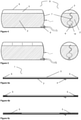
- Figures 1 and 2 display a side-view of the situation wherein a liquid-stabilizing inliner of the invention resides outside a tank container in an unfolded and non-rolled-up state, while the inliner is empty (and flat) and the inflatable unit is inflated (and not flat).
- the inflatable unit consists of one compartment; in Figure 2 it consists of four compartments that are in fluid connection with each other by a small opening between the compartments.
- the representations in Figures 1 and 2 do course not display a situation of normal use of the liquid-stabilizing inliner (because then the liquid-stabilizing inliner itself would be inside a tank container and the inliner would contain a liquid), but they clearly demonstrate how the inflatable unit is positioned relative to the inliner.
- Figure 3 is a top-view of a flat liquid-stabilizing inliner wherein the inflatable unit is not inflated and the inliner is empty.
- the inflatable unit grey-shaded
- the inliner and the inflatable unit have an equal length, but a different width.
- the inflatable unit comprises four compartments that are in fluid connection with each other by a small opening between the compartments.
- the inflatable unit usually comprises means for inflating the unit, such as an element selected from the group of a valve, a tube and a container with compressed gas.
- a valve and/or a tube are present, they are connected to the unit.
- a tube (7) may pass the wall of the tank container at a suitable location or is connected to a venting hole of the tank container. This allows inflation of the inflatable unit from the outside of the tank container. This is shown in Figures 4 and 5 .
- Figure 4 displays an assembly of a liquid-stabilizing inliner according to the invention and a tank container, wherein the inflatable unit consists of one compartment.
- Figure 5 displays this liquid-stabilizing inliner with four compartments in the inflatable unit.
- the inflatable unit is connected to the inliner. It is in particular connected to a surface of the inliner wall. It may be connected to the inner surface of the inliner wall or to the outer surface of the inliner wall. When present in the interior space, it is connected to the inner surface; when present in the exterior environment, it is connected to the outer surface. When present in the interior space, the inflatable unit may be considered as being a compartment of the interior space.
- the inflatable unit When present in the exterior environment, the inflatable unit is typically connected to the outer surface of the inliner wall. Preferably, the inflatable unit is then connected to the inliner by means of at least two connections. It is however also possible that it is connected with only one connection.
- connection between the inliner and the inflatable unit may be obtained by sealing both items together.
- the film material of the inliner wall as well as the film material of the inflatable unit is made of a sealable material, such as a material that comprises a polyolefin, in particular polyethylene.
- a sealable material such as a material that comprises a polyolefin, in particular polyethylene.
- both film materials are the same (since this usually provides the best sealing result).
- Differences in the materials are however allowed, for example the presence of a barrier layer.
- the material of the inflatable unit does not require a barrier layer, while this is preferred for the material of the inliner itself. Sealing of materials that differ only in the presence of such barrier layer has been shown to still provide a connection with sufficient strength and durability.
- connection by means of sealing may be performed by squeezing a part of the inflatable unit (preferably an edge) on top of a part of the inliner (preferably also an edge) in a press under the addition of heat (heat sealing).
- the resulting sealing line then connects both parts.
- Such sealing line may have a width in the range of 2-20 cm.
- the connections of the inflatable unit with the inliner may comprise a sealing, in particular a heat sealing.
- connection is made by means of sealing tape.
- This may be tape that sticks on both sides. Its application may require heating the tape and the two surfaces that are to be connected, but its application may also be performed at ambient temperature.
- the inflatable unit as well as the inliner are of an elongated shape.
- Such shapes have a longitudinal dimension in the direction wherein the shape is elongated.
- the longitudinal dimensions of the inliner and the inflatable unit are aligned when the inliner is connected to the inflatable unit (such coinciding longitudinal dimensions then form the longitudinal dimension of the liquid-stabilizing inliner according to the invention).
- the inflatable unit may be connected to the inliner over the entire length of the inflatable unit.
- a first connection between the inflatable unit and the inliner is located at or near a first end of the inliner; and a second connection is located at or near a second end of the inliner.
- Such mode of connection keeps both items aligned and causes an effective damping of the sloshing when applied in a tank container.
- more connections are present between the first connection and the second connection.
- liquid-stabilizing inliner may be one wherein
- the inflatable unit may also have a second function when the liquid-stabilizing inliner is used in a tank container. It may function as a handle, which has a twofold advantage; 1) for removing the liquid-stabilizing inliner after use; and 2) for optimal discharge of last traces of liquid from the inliner.
- any amount of liquid that remains in the inliner after its removal is essentially a lost amount, because recovery of the liquid from the inliner at that stage is highly undesired, for example because the sterility has been lost and product quality cannot be guaranteed anymore.
- the first difficulty is overcome in the following way.
- the operator can reach it and pick it up from outside the tank container, through the manhole. By pulling it, he can remove the entire liquid-stabilizing inliner from the tank container.
- the second difficulty is overcome in the following way.
- the operator starts pulling at a section of the inflatable unit that is connected to the most remote end of the liquid-stabilizing inliner, then this side is the first part to be lifted up a little bit so that any traces of liquid in this end of the inliner flow towards the discharge opening of the container.
- the remote end is moving towards to operator and any further traces of liquid are also guided to the discharge opening.
- the last traces of the liquid can be discharged from the tank container.
- This leads to an inliner of less weight, which facilitates the removal of the inliner from the tank container (and so also even more helps to overcome the first difficulty).
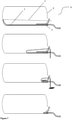
- Figure 7 displays in a series of four cross-sectional views how the liquid-stabilizing inliner may be removed from the tank container via the manhole whilst last traces of liquid are discharged from the inliner. This occurs by pulling at the (deflated) inflatable unit with a pulling unit, although an operator may also perform this pulling.
- the opening in the inliner wall merges into a spout that is removably connected to the drain hole of the tank container.
- FIG. 7 shows that the inflatable unit is connected to that end of the inliner that is most remote from the manhole and the drain hole of the tank container. By pulling at the inflatable unit, the remote end is moved towards the manhole. A pulling mechanism is placed close to the manhole to support the pulling, although this may in principle also be performed manually.
- the progression of pulling the inliner is displayed.
- the removal of the inliner is approximately halfway.
- the inliner has almost completely been removed from the tank container.
- the removal has now arrived at the stage where the inliner needs to be disconnected from the tank container, which is typically the removal of the spout of the inliner from the drain hole of the tank container.
- the fourth view displays the tank container after the liquid-stabilizing inliner has been completely removed from the tank container.
- the inflatable unit solves three problems at the same time; 1) it reduces the sloshing (i.e. stabilizes the liquid); 2) it facilitates the removal of the inliner from the tank container; and 3) it increases amount of liquid that is recovered from the tank container.
- the inliner instead of making separate functionalizations on the inliner to solve these three problems (regardless of how these functionalizations might look like), there is now only one elegant modification of the inliner that solves all three problems at once. This makes the inliner less complicated, less vulnerable to malfunctioning, and easier to handle.
- connection at or near the remote end is located exactly at the remote end or at a small distance therefrom. Such distance is then not more than 25% of the length of the inliner.
- connection at or near the other end i.e. the one close to the operator
- a liquid-stabilizing inliner according to the invention is preferably one wherein there is no connection between the inliner and the inflatable unit over a distance in the longitudinal dimension of at least 50% of the inliner's length, measured over the surface of the inliner, preferably at least 75%.
- the connections are located at each respective end of the inliner, so that the pulling and emptying goes even more smoother and effective.
- the first end of the inliner is then connected to the first end of the inflatable unit and the second end of the inliner is connected to the second end of the inflatable unit.
- the inliner and the inflatable unit in principle have equal lengths (when measured over their surfaces), or at least lengths with a minimal difference, for example with a difference of less than 1%.
- the short edges of the inliner then coincide with at least a part of the short edges of the inflatable unit, as is also the case with e.g. the liquid-stabilizing inliner of Figure 3 (the long edges are of the same length, but the short edges are not).
- Figure 6 visualizes how the lengths over which the inliner is connected to the inflatable unit may differ.
- the bottom bold line in each view represents the inliner and the somewhat slimmer line above it represents the inflatable unit.
- the patterned areas between the ends of the lines represent the connection area between both lines, for example a connection via a sealing.
- connection area is limited. It is typically a small sealing line of e.g. a 2-10 centimeters wide. This is the mostly preferred connection, because it achieves the best removal of liquid from those parts of the inliner that are most remote from the opening (good lifting of the remote end when the (empty) inflatable unit pulls the end up).
- this mode of connection has advantages in the manufacturing.
- the connection area is a bit larger.
- the area is at its maximum allowable of 25% of the length of the inliner. The collection of liquid will be poorer and/or less convenient with the area of Figure 6b and even poorer and/or even less convenient with the area of Figure 6c .
- connection of the inliner with the inflatable unit there is only one connection of the inliner with the inflatable unit.
- Such single connection is then located at one end of the inliner and/or at distance therefrom of 25% of the inliner's length.
- the particular end where the connection is located is the end that is most remote from the opening for the entrance of the liquid in the inliner. This is because, when the inliner is placed in a tank container, that connection is most remote from the manhole.
- the free end of the inflatable unit is then closest to the manhole.
- the inflatable unit may in principle be connected to any type of inliner that is suitable for use in a tank container.
- the inliner may for example be of a type wherein the inliner wall is made from a single piece of fillm material. This may concern a type wherein the entire wall lacks joints that connect different parts of the wall to each other. The only joint that can eventually be present in such wall is a joint around the opening in the wall, typically a joint that connects the wall with a spout.
- the inliner wall comprises a single piece of film material in the form of a tubular wall.
- Such tubular wall comprises a circumferential wall between two open ends, each of which comprises a circumferential edge.
- an interior space is formed that is completely closed-off from the exterior environment.
- Such closure is typically performed by connecting opposite positions of the circumferential edge, in a way that is similar to how e.g. a plastic tube for e.g. toothpaste is closed at the end opposite to the end with the cap.
- the closure may achieved by squeezing each edge in a press under the addition of heat.
- the resulting sealing line then connects opposing portions of the tubular film, thereby closing the open end of the tubular film.
- Inliners of this type typically have a rectangular shape, having two edges substantially parallel to the sealing lines and two edges substantially perpendicular to the sealing lines.
- the inliner wall comprises a tubular film having a first end and a second end, each of which is closed by means of a sealing line that connects at each end opposing portions of the tubular film, to thereby define the interior space for storing a liquid, wherein
- the central line is a line that is centered between both long edges of the inliner.
- Yet another way of arranging a single piece of film material to form the inliner wall comprises
- the interior space is not present inside the original tubular film, but between two portions thereof.
- the inliner may also be of a type wherein the inliner wall is made from a plurality of pieces of material (as compared to the single piece of tubular film mentioned hereinabove).
- the inliner is made from at least two stacked sheets, typically rectangular sheets, that are connected at their edges and so form a closed compartment (i.e. the interior space for storing a liquid).
- the inliner wall When the inliner wall is double-layered, there is less chance on leaking in case there is a puncture in one of the sheets. For example, when four of such stacked sheets are connected at their edges, the interior space for storing a liquid is formed between the second and the third stacked layer. All the inliner walls of the resulting inliner are then double-layered walls. Therefore, preferably, the inliner is made of four (or more) sheets that are sealed together.
- the inliner wall comprises at least two, preferably four, sheets of a rectangular shape lying on top of each other and being sealed together at their edges so as to configure the bag that defines the interior space for storing a liquid, wherein
- the central line is a line that is centered between both long edges of the inliner.
- An alternative way to arrive at an inliner that comprises four layers of film material is by connecting two stacked pieces of tubular film at their edges.
- the interior space so created is not inside the original tubular film, but between two stacked pieces of tubular film, similar to how the space with four separate sheets is formed (as described hereinabove).
- the inliner itself comprises a variation in the position and number of the sealed edges.
- An inliner may comprise one, two, three or four sealed edges.
- the inflatable unit is also part of these sealed edges. This means that in the actual sealing, the different inliner layers as well as the material of the inflatable unit are combined in one seal.
- the first end of the inflatable unit is connected to an edge of the inliner at the first end of the inliner, and the second end of the inflatable unit is connected to an edge of the inliner at the second end of the inliner.
- the inflatable unit when the inflatable unit is of a rectangular shape having two long edges and two short edges, one short edge of the inflatable unit is connected to one short edge of the inliner and the other short edge of the inflatable unit is connected to the other short edge of the inliner, preferably by sealing the respective edges together.
- Such combination of the inflatable unit with the sealed edges has the advantage that the inflatable unit does not cause tensions at the inliner's surface. This reduces the risk that the inliner is torn open after repeated loading of the connection.
- Another advantage is that there is a large distance between the two connections, i.e. there is no connection between the inliner and the inflatable unit over a long distance in the longitudinal dimension. This distance may even be as long as the length of the inliner (measured over the surface of the inliner) minus twice the width of the sealing that connects the inliner and the inflatable unit. A longer distance facilitates the pulling of the liquid-stabilizing inliner out of the tank container, and at the same time the collection of liquid at the discharge opening of the tank is container is more effective.
- the distance over which there is no connection between the inliner and the inflatable unit in the longitudinal dimension may also be at least 50% of the inliner's length, measured over the surface of the inliner, preferably at least 75%, more preferably at least 85% and even more preferably at least 95%.
- the inliner When the inliner is made by sealing a stack of elongated film material (tubular or layered) at its edges (as elaborated hereinabove), then it is of a cylindrical shape having squeezed ends when it would be inflated in the absence of a tank container.
- a liquid-stabilizing inliner according to the invention can be regarded as a composition of two cylinders of the same length but with different diameter, wherein both cylinders are aligned and their edges are squeezed and combined in one single seal.
- the ratio of the diameter of both cylinders is then preferably in the range of 1.0 : 0.25 to 1.0 : 1.0.
- the inliner when placed into a commonly used tank container with a cylindrical shape of an inner diameter of approximately 2.35 m, the inliner preferably has a cylinder diameter in the range of 2.40 - 3.20 m, and the inflatable unit preferably has a cylinder diameter in the range of 0.60 - 3.20 m, more preferably in the range of 0.80 - 2.80 m. It may also be in the range of 1.0 - 2.40 m.
- Figure 3 displays a top-view of a flat liquid-stabilizing inliner where the diameter of the inflatable unit is approximately half the diameter of the inliner.
- the outer rectangle represents the inliner, while the grey-shaded and smaller rectangle represents the inflatable unit.
- the inflatable unit shares one of its walls with a wall of the inliner. This is typically the case when a sheet is connected along all its edges to a part of the inliner wall.
- the inliner is of the type that is made by sealing rectangular sheets and/or tubular films along all of their edges (as elaborated hereinabove)
- the inliner with the inflatable unit can simply be formed by stacking another sheet of the same size on top of the stack, followed by sealing all layers together.
- a liquid-stabilizing inliner is formed wherein the inflatable unit and the inliner share one and the same wall and are thus integrated.
- such inflatable unit will be termed an integrated inflatable unit.
- the integrated inflatable unit has the same width as the inliner itself. This large width is advantageous when there is a large surface of the liquid that needs to be covered by the inflatable unit. This is for example the case when the liquid in the tank container reaches a height of less than 80% of the height of the tank container.
- a liquid-stabilizing inliner of the invention may comprise an intermediate inflatable unit that is present between the inliner and the inflatable unit, wherein
- liquid-stabilizing inliner parts of the inliner, the intermediate inflatable unit and the inflatable unit are typically connected in one sealing. This means that at each end of the liquid-stabilizing inliner, a short edge of the inliner, a short edge of the intermediate inflatable unit and a short edge of the inflatable unit are combined in one sealing.
- the inflatable unit may comprise one single compartment, but it is also possible that a plurality of compartments is present. These may be separately inflatable, but they may also be interconnected by air channels. When a valve is present for inflation, interconnected compartments may be inflated from a single valve. When the compartments are not connected, then a plurality of valves would be required.
- Figure 1 displays a liquid-stabilizing inliner according to the invention wherein the inflatable unit comprises a single compartment.
- Figure 2 displays the situation wherein the inflatable unit comprises a plurality of compartments.
- the different compartments are connected via air channels, so that they can be inflated by one single inlet of gas.
- Figure 3 displays a top-view of a flat-lying liquid-stabilizing inliner of the invention wherein the inflatable unit comprises a plurality of compartments.
- An advantage of a plurality of inflated compartments is that the inflatable unit in its totality can be made more rigid and so achieves a better damping of the waves of the liquid that is present in the inliner.
- the air channels that connect the compartments By making the air channels that connect the compartments small enough, distribution of the gas over the different compartments is slow as compared to the movement of the liquid (speed of propagation of a wave of the liquid). In this way, a plurality of compartments (as e.g. shown in Figure 2 ) can be more effective in damping the waves.
- the invention further relates to a method for preparing a liquid-stabilizing inliner as described hereinabove, comprising
- the inliner as well as the inflatable unit are preferably made of a sealable plastic, so that the connecting step in the method may be performed by sealing the inflatable unit to the inliner.
- the method comprises
- the at least two sheets may also be two tubular films. This effectively forms a stack of four sheets, wherein the bottom two sheets are connected at their long edges (because they are part of one tubular film) and the top two sheets are also connected at their long edges form (because they are part of the other tubular film).
- the invention further relates to an assembly comprising a liquid-stabilizing inliner as described hereinabove and a tank container for the transport and/or storage of a liquid, wherein
- the opening in the inliner wall preferably comprises a spout.
- the alignment of the opening in the inliner wall with the drain hole of the tank container is usually achieved by placing the spout of the inliner wall into the drain hole of the tank container, so that a fluid connection is realized between the interior space of the inliner and the exterior environment.
- the inliner is present inside the tank container. It has to be brought into the tank container via an opening different from the drain hole. Therefore, the tank container comprises a hole that is large enough for the (folded) inliner to pass through.
- a hole is a manhole, e.g. a hole that is large enough for one person to pass through, e.g. a hole with a diameter in the range of 25-50 cm (for placement of the liquid-stabilizing inliner of the invention into the tank container it is in principle not necessary for a person to go into the tank container).
- the hole is usually equipped with a door to close-off the hole.
- the manhole is located close to the drain hole, so that the positioning of the inliner in the tank container is easy to carry out, in particular the placement of the spout of the inliner into the drain hole.
- the tank container also comprises a venting hole for the release of air during the filling of the container.
- the tank container When the assembly is in use for the storage and/or transport of a liquid, the tank container (and thus in the inliner) may be partly filled with a liquid and the inflatable unit at least partly inflated so that the inflatable unit is squeezed between the inliner and the circumferential wall of the tank container.
- the invention further relates to a method for preparing the assembly, the method comprising
Landscapes
- Engineering & Computer Science (AREA)
- Mechanical Engineering (AREA)
- Bag Frames (AREA)
- Filling Or Discharging Of Gas Storage Vessels (AREA)
- Details Of Rigid Or Semi-Rigid Containers (AREA)
Claims (15)
- Flüssigkeitsstabilisierender Inliner (1) zur Verwendung in einem Tankcontainer, der einen Inliner (2) umfasst, der eine Inlinerwand aufweist, die aus einem Folienmaterial gefertigt ist, wobei die Inlinerwand- als ein Beutel konfiguriert ist, um einen Innenraum zum Aufbewahren einer Flüssigkeit zu definieren;- eine Öffnung für den Eintritt der Flüssigkeit in den Innenraum aufweist;- eine Innenoberfläche, die dem Innenraum zugewandt ist, und eine Außenoberfläche aufweist, die einer Außenumgebung zugewandt ist;dadurch gekennzeichnet, dass eine aufblasbare Einheit (3) mit dem Inliner (2) verbunden ist, wobei die aufblasbare Einheit (3) ein Folienmaterial umfasst, das als ein Beutel konfiguriert ist, um einen Innenraum zum Aufnehmen eines Gases zu definieren.
- Flüssigkeitsstabilisierender Inliner (1) nach Anspruch 1, wobei die Inlinerwand wenigstens zwei, vorzugsweise vier, Bahnen umfasst, die eine rechteckige Form haben, die aufeinander liegen und an ihren Kanten miteinander versiegelt sind, um den Beutel auszubilden, der den Innenraum zum Aufbewahren einer Flüssigkeit definiert, wobei- der Inliner (2) zwei lange Kanten und zwei kurze Kanten umfasst;- eine Längsabmessung zwischen den zwei kurzen Kanten des Inliners (2) vorhanden ist;- die Öffnung in einen Ausfluss (4) übergeht und auf einer Mittellinie oder angrenzend an dieser positioniert ist, die sich entlang der Längsabmessung des Inliners (2) erstreckt.
- Flüssigkeitsstabilisierender Inliner (1) nach Anspruch 1, wobei die Inlinerwand ein Stück Schlauchfolie umfasst, die eine rechteckige Form hat, die zwei Enden aufweist, von denen jedes mittels einer Siegellinie verschlossen ist, die an jedem Ende gegenüberliegende Abschnitte der Schlauchfolie verbindet, um dadurch den Beutel auszubilden, der den Innenraum zum Aufbewahren einer Flüssigkeit definiert, wobei- der Inliner (2) zwei lange Kanten und zwei kurze Kanten umfasst;- eine Längsabmessung zwischen den zwei kurzen Kanten des Inliners (2) vorhanden ist;- die Öffnung in einen Ausfluss (4) übergeht und auf einer Mittellinie oder angrenzend an dieser positioniert ist, die sich entlang der Längsabmessung des Inliners (2) erstreckt.
- Flüssigkeitsstabilisierender Inliner (1) nach einem der Ansprüche 1 -3, wobei- die aufblasbare Einheit (3) sowie der Inliner (2) eine längliche Form haben, insbesondere eine rechteckige Form, die jeweils ein erstes Ende und ein zweites Ende, eine Längsabmessung zwischen beiden Enden und eine Länge aufweisen, die als der Abstand zwischen dem ersten Ende und einem zweiten Ende definiert ist, der über der Oberfläche der aufblasbaren Einheit (3) beziehungsweise des Inliners (2) gemessen wird;- die relative Orientierung des Inliners (2) und der aufblasbaren Einheit (3) derart ist, dass ihre Längsabmessungen ausgerichtet sind;- die aufblasbare Einheit (3) in der Außenumgebung vorhanden ist;- die aufblasbare Einheit (3) mit dem Inliner (2) mittels wenigstens zwei Verbindungen (5) verbunden ist, wobei sich eine erste Verbindung (5) an dem ersten Ende des Inliners und/oder in einem Abstand davon von nicht mehr als 25 % der Länge des Inliners befindet, der über die Oberfläche des Inliners (2) gemessen wird; und eine zweite Verbindung (5) - unabhängig von der ersten Verbindung (5) - an dem zweiten Ende des Inliners und/oder in einem Abstand davon von nicht mehr als 25 % der Länge des Inliners befindet, der über die Oberfläche des Inliners (2) gemessen wird.
- Flüssigkeitsstabilisierender Inliner (1) nach Anspruch 4, wobei zwischen dem Inliner (2) und der aufblasbaren Einheit (3) über einen Abstand in der Längsabmessung von wenigstens 50 % der Länge des Inliners keine Verbindung (5) besteht, der über die Oberfläche des Inliners (2), vorzugsweise von wenigstens 75 % der Länge des Inliners, gemessen wird.
- Flüssigkeitsstabilisierender Inliner (1) nach Anspruch 4 oder 5, wobei das erste Ende des Inliners (2) mit dem ersten Ende der aufblasbaren Einheit (3) verbunden ist und das zweite Ende des Inliners (2) mit dem zweiten Ende der aufblasbaren Einheit (3) verbunden ist.
- Flüssigkeitsstabilisierender Inliner (1) nach einem der Ansprüche 4-6, wobei die wenigstens zwei Verbindungen (5) der aufblasbaren Einheit (3) mit dem Inliner (2) eine Versiegelung umfassen, zum Beispiel eine Siegellinie mit einer Breite in dem Bereich von 2-20 cm.
- Flüssigkeitsstabilisierender Inliner (1) nach Anspruch 2 oder 3, wobei- die aufblasbare Einheit (3) eine rechteckige Form hat, die zwei lange Kanten und zwei kurze Kanten aufweist;- eine kurze Kante der aufblasbaren Einheit (3) mit einer kurzen Kante des Inliners (2) verbunden ist und die andere kurze Kante der aufblasbaren Einheit (3) mit der anderen kurzen Kante des Inliners (2) verbunden ist, vorzugsweise durch das Versiegeln der jeweiligen Kanten miteinander.
- Flüssigkeitsstabilisierender Inliner (1) nach Anspruch 8, wobei eine dazwischenliegende aufblasbare Einheit zwischen dem Inliner (2) und der aufblasbaren Einheit (3) vorhanden ist, wobei- die Wand der dazwischenliegenden aufblasbaren Einheit durch einen Teil der Inlinerwand und einer Bahn ausgebildet ist, die entlang ihrer Kanten mit diesem Teil der Inlinerwand versiegelt ist, sodass die dazwischenliegende aufblasbare Einheit und der Inliner (2) einen Teil ihrer Wände teilen;- die aufblasbare Einheit (3) auf der Oberseite der dazwischenliegenden aufblasbaren Einheit vorhanden ist.
- Verfahren zum Herstellen eines flüssigkeitsstabilisierenden Inliners (1) nach einem der Ansprüche 1-9, wobei das Verfahren Folgendes umfasst:- Bereitstellen eines Inliners (2), der eine Inlinerwand aufweist, die aus einem Folienmaterial gefertigt ist, wobei die Inlinerwand∘ als ein Beutel konfiguriert ist, um einen Innenraum zum Aufbewahren einer Flüssigkeit zu definieren;∘ eine Öffnung für den Eintritt der Flüssigkeit in den Innenraum aufweist;∘ eine Innenoberfläche, die dem Innenraum zugewandt ist, und eine Außenoberfläche aufweist, die einer Außenumgebung zugewandt ist;- Bereitstellen einer aufblasbaren Einheit (3), wobei die aufblasbare Einheit (3)∘ eine längliche Form hat, die ein erstes Ende und ein zweites Ende aufweist;∘ in dem Innenraum oder in der Außenumgebung vorhanden ist;- Verbinden der aufblasbaren Einheit (3) mit dem Inliner (2), insbesondere Verbinden des ersten Endes mit einem Teil des Inliners (2) und Verbinden des zweiten Endes mit einem anderen Teil des Inliners (2).
- Verfahren zum Herstellen eines flüssigkeitsstabilisierenden Inliners (1) nach einem der Ansprüche 1-9, wobei das Verfahren Folgendes umfasst:- Bereitstellen eines Stapels von Bahnen aus einem versiegelbaren Material, wobei der Stapel Folgendes umfasst:∘ wenigstens zwei, vorzugsweise vier, Bahnen, die übereinander liegen, wobei die Bahnen eine rechteckige Form haben und zwei kurze Kanten und zwei lange Kanten aufweisen; und∘ ein Stück Schlauchfolie, das eine rechteckige Form hat und zwei kurze Kanten und zwei lange Kanten aufweist, wobei die langen Kanten die gleiche Länge wie die langen Kanten der wenigstens zwei Bahnen aufweisen und wobei die kurzen Kanten die gleiche Länge wie die kurzen Kanten der wenigstens zwei Bahnen haben oder kürzer als diese sind, wobei die Schlauchfolie auf den wenigstens zwei Bahnen liegt, sodass ihre kurzen Kanten mit den kurzen Kanten der wenigstens zwei Bahnen zusammenfallen; danach- Versiegeln der langen Kanten der wenigstens zwei Bahnen; und- Versiegeln der kurzen Kanten der wenigstens zwei Bahnen zusammen mit den kurzen Kanten der Schlauchfolie.
- Anordnung (8) eines flüssigkeitsstabilisierenden Inliners (1) nach einem der Ansprüche 1-9 und eines Tankcontainers (6) für den Transport und/oder die Lagerung einer Flüssigkeit, wobei- der Tankcontainer (6)∘ eine zylinderartige Form hat und ein erstes Ende, ein zweites Ende und eine Längsabmessung umfasst, die zwischen dem ersten Ende und dem zweiten Ende vorhanden ist;∘ eine Umfangswand umfasst, die zwischen einer Wand an dem ersten Ende und einer Wand an dem zweiten Ende vorhanden ist;∘ ein Ablaufloch (9) in einer der Wände umfasst;∘ eine Einsteigöffnung (10) in einer der Wände zum Einsetzen und Entfernen des flüssigkeitsstabilisierenden Inliners (1) umfasst;- der flüssigkeitsstabilisierende Inliner (1) im Inneren des Tankcontainers (6) auf eine Weise vorhanden ist, wobei∘ die Öffnung in der Inlinerwand an dem Ablaufloch (9) des Tankcontainers (6) ausgerichtet ist;∘ der flüssigkeitsstabilisierende Inliner (1) solchermaßen orientiert ist, dass die aufblasbare Einheit (3) an die Längsabmessung des Tankcontainers (6) ausgerichtet ist.
- Anordnung (8) nach Anspruch 12, wobei der Tankcontainer (6) teilweise mit einer Flüssigkeit gefüllt ist und die aufblasbare Einheit (3) wenigstens teilweise aufgeblasen ist, sodass die aufblasbare Einheit (3) zwischen den Inliner (2) und die Umfangswand des Tankcontainers (6) gepresst wird.
- Verfahren zum Herstellen einer Anordnung (8) nach Anspruch 12 oder 13, das Folgendes umfasst:- Bereitstellen eines Tankcontainers (6), der∘ eine zylinderartige Form hat und ein erstes Ende, ein zweites Ende und eine Längsabmessung umfasst, die zwischen dem ersten Ende und dem zweiten Ende vorhanden ist;∘ eine Umfangswand umfasst, die zwischen einer Wand an dem ersten Ende und einer Wand an dem zweiten Ende vorhanden ist;∘ ein Ablaufloch (9) in einer der Wände umfasst;∘ eine Einsteigöffnung (10) in einer der Wände zum Einsetzen und Entfernen des flüssigkeitsstabilisierenden Inliners (1) umfasst; danach- Bereitstellen eines flüssigkeitsstabilisierenden Inliners (1) nach einem der Ansprüche 1-9; danach- Bringen des flüssigkeitsstabilisierenden Inliners (1) in das Innere des Tankcontainers (6) durch ein Hindurchführen durch die Einsteigöffnung (10); danach- Ausrichten der Öffnung in der Inlinerwand an dem Ablaufloch (9) des Tankcontainers (6); und- Orientieren des flüssigkeitsstabilisierenden Inliners (1) solchermaßen, dass die aufblasbare Einheit (3) an der Längsabmessung des Tankcontainers (6) ausgerichtet ist.
- Verfahren nach Anspruch 14, gefolgt von- teilweisem Füllen des Inliners (2) mit einer Flüssigkeit; danach- wenigstens teilweisem Aufblasen des aufblasbaren Gegenstands (3).
Applications Claiming Priority (2)
| Application Number | Priority Date | Filing Date | Title |
|---|---|---|---|
| NL2021873A NL2021873B9 (en) | 2018-10-25 | 2018-10-25 | Liquid stabilizing inliner for a tank container |
| PCT/NL2019/050700 WO2020085906A1 (en) | 2018-10-25 | 2019-10-24 | Liquid stabilizing inliner for a tank container |
Publications (2)
| Publication Number | Publication Date |
|---|---|
| EP3870525A1 EP3870525A1 (de) | 2021-09-01 |
| EP3870525B1 true EP3870525B1 (de) | 2022-02-16 |
Family
ID=65496935
Family Applications (1)
| Application Number | Title | Priority Date | Filing Date |
|---|---|---|---|
| EP19828893.8A Active EP3870525B1 (de) | 2018-10-25 | 2019-10-24 | Flüssigkeitsstabilisierende einlage für einen tankcontainer, herstellungsverfahren einer einlage und herstellungsverfahren eines tankcontainers |
Country Status (5)
| Country | Link |
|---|---|
| US (1) | US11524840B2 (de) |
| EP (1) | EP3870525B1 (de) |
| CN (1) | CN113165800B (de) |
| NL (1) | NL2021873B9 (de) |
| WO (1) | WO2020085906A1 (de) |
Families Citing this family (2)
| Publication number | Priority date | Publication date | Assignee | Title |
|---|---|---|---|---|
| NL2021873B9 (en) * | 2018-10-25 | 2020-07-21 | Mega Inliner Int Group Bv | Liquid stabilizing inliner for a tank container |
| US20200354143A1 (en) * | 2019-05-07 | 2020-11-12 | Scott Houle | Inflatable bladder system for bulk liquid transport |
Family Cites Families (33)
| Publication number | Priority date | Publication date | Assignee | Title |
|---|---|---|---|---|
| US5059084A (en) * | 1983-06-09 | 1991-10-22 | Bjk Industries, Inc. | Vacuum apparatus for installing a water proof liner |
| JPH03256887A (ja) * | 1990-02-26 | 1991-11-15 | Yokohama Rubber Co Ltd:The | 輸送用ゴム袋における流動物移動抑制装置 |
| EP0538563B1 (de) * | 1991-07-30 | 1997-04-09 | Insta-Bulk, Inc. | Kombination einer Behälterauskleidung mit einem Behälter |
| GB2349633B (en) | 1999-05-04 | 2002-07-10 | Brendan Mckenna | Apparatus and method for use in the transportation of fluids and particulate matter |
| US6726052B1 (en) * | 2003-03-19 | 2004-04-27 | The United States Of America As Represented By The Secretary Of The Army | Collapsible fluid transport tank |
| US20070095423A1 (en) * | 2005-10-19 | 2007-05-03 | Fres-Co System Usa, Inc. | Apparatus and method for filling void in an outer container having a liquid-containing flexible package held therein |
| NL1030882C2 (nl) * | 2006-01-10 | 2007-07-11 | Erik Jeroen Eenkhoorn | Opblaasbaar element voor toepassing en/of gebruik in het inwendige van een houder van een transport- of opslaginrichting; werkwijze voor het opblazen ervan. |
| CN101003313A (zh) * | 2006-01-20 | 2007-07-25 | 查里斯·M·倪尔森 | 用于运送散装材料的柔性罐 |
| CN101121459A (zh) * | 2007-09-11 | 2008-02-13 | 段云平 | 集装箱空隙填充独立气道式充气包 |
| CN101342959A (zh) * | 2008-08-01 | 2009-01-14 | 中绵集装箱袋(惠州)有限公司 | 存储容器内衬装置及其使用方法 |
| ES2558060T3 (es) * | 2010-06-17 | 2016-02-01 | Likua Endustriyel Ambalaj Malzm.San.Ve Tic.Ltd.Sti | Un depósito flexible para el transporte de líquidos |
| US20140097182A1 (en) * | 2012-10-10 | 2014-04-10 | SandCan Inc. | Intermodal container having a resilient liner |
| DE102013002576B4 (de) | 2013-02-12 | 2019-10-17 | Arianegroup Gmbh | Behälter zum Transport von Flüssigkeiten |
| CN204078516U (zh) * | 2014-09-23 | 2015-01-07 | 沈科 | 软质多功能储运罐内胆和储运罐 |
| US20160130078A1 (en) * | 2014-11-06 | 2016-05-12 | i3 Capital Partners, LLC | Bladder Systems for Dual Use of Truck Tanks |
| CA3026579C (en) * | 2015-06-05 | 2024-10-22 | Intermodal Sciences, Llc | CONTAINER FOR TRANSPORTING BULK LIQUIDS USING ENCLOSED TRAILERS |
| US11634273B2 (en) * | 2016-02-10 | 2023-04-25 | Ilc Dover Ip, Inc. | Flexible container liner wringing device and liner |
| US20170225885A1 (en) * | 2016-02-10 | 2017-08-10 | Ilc Dover Ip, Inc. | Flexible container liner wringing device and liner |
| CA2959167C (en) * | 2016-03-02 | 2026-03-03 | Thinktank Products Inc. | Bladder for containment vessel |
| NL2018765B1 (en) * | 2017-04-24 | 2018-11-05 | Green Eye Capital B V | Assembly of an inliner and a tank container |
| US10926948B2 (en) * | 2017-05-24 | 2021-02-23 | Ilc Dover Ip, Inc. | Liner with lifting cradle |
| US10836298B1 (en) * | 2017-06-13 | 2020-11-17 | Ty F Bonnar | Bulk liquid flexible tank system |
| TR201710010A2 (tr) * | 2017-07-07 | 2017-09-21 | Likua Enduestriyel Ambalaj Malzm San Ve Tic Ltd Sti | Bi̇r esnek tank |
| CN107472723B (zh) * | 2017-08-03 | 2024-07-02 | 上海鸿研物流技术有限公司 | 流体排放系统及其挤推器 |
| CN108455109A (zh) * | 2018-04-26 | 2018-08-28 | 汤树林 | 一种模块化无限容积组合罐 |
| GB2574465A (en) * | 2018-06-07 | 2019-12-11 | Trans Ocean Bulk Logistics Ltd | Vent |
| US20190375582A1 (en) * | 2018-06-09 | 2019-12-12 | Ondrej Kotora | Dual purpose unrefined/refined petroleum intermodal tank container |
| US11691808B2 (en) * | 2018-06-09 | 2023-07-04 | Ondrej Kotora | Dual purpose intermodal tank container |
| GB2576913A (en) * | 2018-09-06 | 2020-03-11 | Trans Ocean Bulk Logistics Ltd | Flexible tank with a mixing member |
| NL2021873B9 (en) * | 2018-10-25 | 2020-07-21 | Mega Inliner Int Group Bv | Liquid stabilizing inliner for a tank container |
| US11794989B2 (en) * | 2019-03-21 | 2023-10-24 | Jeffery Kevin Archer, Jr. | Pre-assembled, self contained, portable fluid storage tank and method of handling flowback fluids from a hydrocarbon production operation using said tank |
| US20220003360A1 (en) * | 2020-07-02 | 2022-01-06 | Abdulkariem Mukhtar Aljrbi | Aljrbi Tank |
| US20220002075A1 (en) * | 2020-07-04 | 2022-01-06 | Abdulkariem Mukhtar Aljrbi | Aljrbi Updating For Tanks |
-
2018
- 2018-10-25 NL NL2021873A patent/NL2021873B9/en not_active IP Right Cessation
-
2019
- 2019-10-24 US US17/288,270 patent/US11524840B2/en active Active
- 2019-10-24 EP EP19828893.8A patent/EP3870525B1/de active Active
- 2019-10-24 WO PCT/NL2019/050700 patent/WO2020085906A1/en not_active Ceased
- 2019-10-24 CN CN201980079995.6A patent/CN113165800B/zh active Active
Also Published As
| Publication number | Publication date |
|---|---|
| NL2021873B9 (en) | 2020-07-21 |
| US11524840B2 (en) | 2022-12-13 |
| CN113165800B (zh) | 2022-11-15 |
| CN113165800A (zh) | 2021-07-23 |
| EP3870525A1 (de) | 2021-09-01 |
| NL2021873B1 (en) | 2020-05-13 |
| WO2020085906A1 (en) | 2020-04-30 |
| US20210387798A1 (en) | 2021-12-16 |
Similar Documents
| Publication | Publication Date | Title |
|---|---|---|
| ES2230357T3 (es) | Recipiente flexible provisto de paredes planas. | |
| US3383017A (en) | Aerial drop containers | |
| JP3218025U (ja) | 折畳式容器 | |
| US11524840B2 (en) | Liquid stabilizing inliner for a tank container | |
| US20200010266A1 (en) | Design and method of fabrication of collapsible storage tank | |
| US20140144974A1 (en) | Bag, in Particular for Bag-in-Box Packaging | |
| US20100189528A1 (en) | Dunnage bag with double seal reusable inflation valve | |
| US20250368428A1 (en) | Outer Cover for a Flexible Tank and Optimized Flexible Tank for a 40 Foot Shipping Container Without a Bulkhead | |
| US20050108993A1 (en) | Air bladder packing system and process for using the same | |
| US11447332B2 (en) | Assembly of an inliner and a tank container | |
| US20190202631A1 (en) | End-Closure for a Flexible Tank | |
| US20050018930A1 (en) | Flexible tank and method of making such a tank | |
| RU2852066C1 (ru) | Гибкая емкость одноразового использования и способ ее изготовления | |
| RU2156726C1 (ru) | Резервуар для транспортирования и хранения жидкостей | |
| CN212580522U (zh) | 一种防货损液袋 | |
| JPH06191590A (ja) | フレキシブルコンテナ | |
| WO2023062023A2 (de) | Transportbehältnis sowie anordnung aus einem transportbehältnis und wenigstens einem zusatzfunktionsteil | |
| RU105262U1 (ru) | Упаковка для наливных грузов | |
| WO2007015842A2 (en) | Flexible container or bladder | |
| KR20070015964A (ko) | 폴딩된 알코올음료 백 및 방법 |
Legal Events
| Date | Code | Title | Description |
|---|---|---|---|
| STAA | Information on the status of an ep patent application or granted ep patent |
Free format text: STATUS: UNKNOWN |
|
| STAA | Information on the status of an ep patent application or granted ep patent |
Free format text: STATUS: THE INTERNATIONAL PUBLICATION HAS BEEN MADE |
|
| PUAI | Public reference made under article 153(3) epc to a published international application that has entered the european phase |
Free format text: ORIGINAL CODE: 0009012 |
|
| STAA | Information on the status of an ep patent application or granted ep patent |
Free format text: STATUS: REQUEST FOR EXAMINATION WAS MADE |
|
| GRAP | Despatch of communication of intention to grant a patent |
Free format text: ORIGINAL CODE: EPIDOSNIGR1 |
|
| STAA | Information on the status of an ep patent application or granted ep patent |
Free format text: STATUS: GRANT OF PATENT IS INTENDED |
|
| 17P | Request for examination filed |
Effective date: 20210518 |
|
| AK | Designated contracting states |
Kind code of ref document: A1 Designated state(s): AL AT BE BG CH CY CZ DE DK EE ES FI FR GB GR HR HU IE IS IT LI LT LU LV MC MK MT NL NO PL PT RO RS SE SI SK SM TR |
|
| DAV | Request for validation of the european patent (deleted) | ||
| DAX | Request for extension of the european patent (deleted) | ||
| INTG | Intention to grant announced |
Effective date: 20210901 |
|
| GRAS | Grant fee paid |
Free format text: ORIGINAL CODE: EPIDOSNIGR3 |
|
| GRAA | (expected) grant |
Free format text: ORIGINAL CODE: 0009210 |
|
| STAA | Information on the status of an ep patent application or granted ep patent |
Free format text: STATUS: THE PATENT HAS BEEN GRANTED |
|
| AK | Designated contracting states |
Kind code of ref document: B1 Designated state(s): AL AT BE BG CH CY CZ DE DK EE ES FI FR GB GR HR HU IE IS IT LI LT LU LV MC MK MT NL NO PL PT RO RS SE SI SK SM TR |
|
| REG | Reference to a national code |
Ref country code: GB Ref legal event code: FG4D |
|
| REG | Reference to a national code |
Ref country code: CH Ref legal event code: EP |
|
| REG | Reference to a national code |
Ref country code: DE Ref legal event code: R096 Ref document number: 602019011738 Country of ref document: DE |
|
| REG | Reference to a national code |
Ref country code: AT Ref legal event code: REF Ref document number: 1468755 Country of ref document: AT Kind code of ref document: T Effective date: 20220315 |
|
| REG | Reference to a national code |
Ref country code: IE Ref legal event code: FG4D |
|
| REG | Reference to a national code |
Ref country code: NL Ref legal event code: FP |
|
| REG | Reference to a national code |
Ref country code: LT Ref legal event code: MG9D |
|
| REG | Reference to a national code |
Ref country code: AT Ref legal event code: MK05 Ref document number: 1468755 Country of ref document: AT Kind code of ref document: T Effective date: 20220216 |
|
| PG25 | Lapsed in a contracting state [announced via postgrant information from national office to epo] |
Ref country code: SE Free format text: LAPSE BECAUSE OF FAILURE TO SUBMIT A TRANSLATION OF THE DESCRIPTION OR TO PAY THE FEE WITHIN THE PRESCRIBED TIME-LIMIT Effective date: 20220216 Ref country code: RS Free format text: LAPSE BECAUSE OF FAILURE TO SUBMIT A TRANSLATION OF THE DESCRIPTION OR TO PAY THE FEE WITHIN THE PRESCRIBED TIME-LIMIT Effective date: 20220216 Ref country code: PT Free format text: LAPSE BECAUSE OF FAILURE TO SUBMIT A TRANSLATION OF THE DESCRIPTION OR TO PAY THE FEE WITHIN THE PRESCRIBED TIME-LIMIT Effective date: 20220616 Ref country code: NO Free format text: LAPSE BECAUSE OF FAILURE TO SUBMIT A TRANSLATION OF THE DESCRIPTION OR TO PAY THE FEE WITHIN THE PRESCRIBED TIME-LIMIT Effective date: 20220516 Ref country code: LT Free format text: LAPSE BECAUSE OF FAILURE TO SUBMIT A TRANSLATION OF THE DESCRIPTION OR TO PAY THE FEE WITHIN THE PRESCRIBED TIME-LIMIT Effective date: 20220216 Ref country code: HR Free format text: LAPSE BECAUSE OF FAILURE TO SUBMIT A TRANSLATION OF THE DESCRIPTION OR TO PAY THE FEE WITHIN THE PRESCRIBED TIME-LIMIT Effective date: 20220216 Ref country code: ES Free format text: LAPSE BECAUSE OF FAILURE TO SUBMIT A TRANSLATION OF THE DESCRIPTION OR TO PAY THE FEE WITHIN THE PRESCRIBED TIME-LIMIT Effective date: 20220216 Ref country code: BG Free format text: LAPSE BECAUSE OF FAILURE TO SUBMIT A TRANSLATION OF THE DESCRIPTION OR TO PAY THE FEE WITHIN THE PRESCRIBED TIME-LIMIT Effective date: 20220516 |
|
| PG25 | Lapsed in a contracting state [announced via postgrant information from national office to epo] |
Ref country code: PL Free format text: LAPSE BECAUSE OF FAILURE TO SUBMIT A TRANSLATION OF THE DESCRIPTION OR TO PAY THE FEE WITHIN THE PRESCRIBED TIME-LIMIT Effective date: 20220216 Ref country code: LV Free format text: LAPSE BECAUSE OF FAILURE TO SUBMIT A TRANSLATION OF THE DESCRIPTION OR TO PAY THE FEE WITHIN THE PRESCRIBED TIME-LIMIT Effective date: 20220216 Ref country code: GR Free format text: LAPSE BECAUSE OF FAILURE TO SUBMIT A TRANSLATION OF THE DESCRIPTION OR TO PAY THE FEE WITHIN THE PRESCRIBED TIME-LIMIT Effective date: 20220517 Ref country code: FI Free format text: LAPSE BECAUSE OF FAILURE TO SUBMIT A TRANSLATION OF THE DESCRIPTION OR TO PAY THE FEE WITHIN THE PRESCRIBED TIME-LIMIT Effective date: 20220216 Ref country code: AT Free format text: LAPSE BECAUSE OF FAILURE TO SUBMIT A TRANSLATION OF THE DESCRIPTION OR TO PAY THE FEE WITHIN THE PRESCRIBED TIME-LIMIT Effective date: 20220216 |
|
| PG25 | Lapsed in a contracting state [announced via postgrant information from national office to epo] |
Ref country code: IS Free format text: LAPSE BECAUSE OF FAILURE TO SUBMIT A TRANSLATION OF THE DESCRIPTION OR TO PAY THE FEE WITHIN THE PRESCRIBED TIME-LIMIT Effective date: 20220617 |
|
| PG25 | Lapsed in a contracting state [announced via postgrant information from national office to epo] |
Ref country code: SM Free format text: LAPSE BECAUSE OF FAILURE TO SUBMIT A TRANSLATION OF THE DESCRIPTION OR TO PAY THE FEE WITHIN THE PRESCRIBED TIME-LIMIT Effective date: 20220216 Ref country code: SK Free format text: LAPSE BECAUSE OF FAILURE TO SUBMIT A TRANSLATION OF THE DESCRIPTION OR TO PAY THE FEE WITHIN THE PRESCRIBED TIME-LIMIT Effective date: 20220216 Ref country code: RO Free format text: LAPSE BECAUSE OF FAILURE TO SUBMIT A TRANSLATION OF THE DESCRIPTION OR TO PAY THE FEE WITHIN THE PRESCRIBED TIME-LIMIT Effective date: 20220216 Ref country code: EE Free format text: LAPSE BECAUSE OF FAILURE TO SUBMIT A TRANSLATION OF THE DESCRIPTION OR TO PAY THE FEE WITHIN THE PRESCRIBED TIME-LIMIT Effective date: 20220216 Ref country code: DK Free format text: LAPSE BECAUSE OF FAILURE TO SUBMIT A TRANSLATION OF THE DESCRIPTION OR TO PAY THE FEE WITHIN THE PRESCRIBED TIME-LIMIT Effective date: 20220216 Ref country code: CZ Free format text: LAPSE BECAUSE OF FAILURE TO SUBMIT A TRANSLATION OF THE DESCRIPTION OR TO PAY THE FEE WITHIN THE PRESCRIBED TIME-LIMIT Effective date: 20220216 |
|
| REG | Reference to a national code |
Ref country code: DE Ref legal event code: R097 Ref document number: 602019011738 Country of ref document: DE |
|
| PG25 | Lapsed in a contracting state [announced via postgrant information from national office to epo] |
Ref country code: AL Free format text: LAPSE BECAUSE OF FAILURE TO SUBMIT A TRANSLATION OF THE DESCRIPTION OR TO PAY THE FEE WITHIN THE PRESCRIBED TIME-LIMIT Effective date: 20220216 |
|
| PLBE | No opposition filed within time limit |
Free format text: ORIGINAL CODE: 0009261 |
|
| STAA | Information on the status of an ep patent application or granted ep patent |
Free format text: STATUS: NO OPPOSITION FILED WITHIN TIME LIMIT |
|
| 26N | No opposition filed |
Effective date: 20221117 |
|
| PG25 | Lapsed in a contracting state [announced via postgrant information from national office to epo] |
Ref country code: MC Free format text: LAPSE BECAUSE OF FAILURE TO SUBMIT A TRANSLATION OF THE DESCRIPTION OR TO PAY THE FEE WITHIN THE PRESCRIBED TIME-LIMIT Effective date: 20220216 |
|
| REG | Reference to a national code |
Ref country code: CH Ref legal event code: PL |
|
| REG | Reference to a national code |
Ref country code: BE Ref legal event code: MM Effective date: 20221031 |
|
| PG25 | Lapsed in a contracting state [announced via postgrant information from national office to epo] |
Ref country code: LU Free format text: LAPSE BECAUSE OF NON-PAYMENT OF DUE FEES Effective date: 20221024 |
|
| P01 | Opt-out of the competence of the unified patent court (upc) registered |
Effective date: 20230530 |
|
| PG25 | Lapsed in a contracting state [announced via postgrant information from national office to epo] |
Ref country code: LI Free format text: LAPSE BECAUSE OF NON-PAYMENT OF DUE FEES Effective date: 20221031 Ref country code: IT Free format text: LAPSE BECAUSE OF FAILURE TO SUBMIT A TRANSLATION OF THE DESCRIPTION OR TO PAY THE FEE WITHIN THE PRESCRIBED TIME-LIMIT Effective date: 20220216 Ref country code: CH Free format text: LAPSE BECAUSE OF NON-PAYMENT OF DUE FEES Effective date: 20221031 |
|
| PG25 | Lapsed in a contracting state [announced via postgrant information from national office to epo] |
Ref country code: BE Free format text: LAPSE BECAUSE OF NON-PAYMENT OF DUE FEES Effective date: 20221031 |
|
| PG25 | Lapsed in a contracting state [announced via postgrant information from national office to epo] |
Ref country code: IE Free format text: LAPSE BECAUSE OF NON-PAYMENT OF DUE FEES Effective date: 20221024 |
|
| PG25 | Lapsed in a contracting state [announced via postgrant information from national office to epo] |
Ref country code: CY Free format text: LAPSE BECAUSE OF FAILURE TO SUBMIT A TRANSLATION OF THE DESCRIPTION OR TO PAY THE FEE WITHIN THE PRESCRIBED TIME-LIMIT Effective date: 20220216 |
|
| PG25 | Lapsed in a contracting state [announced via postgrant information from national office to epo] |
Ref country code: MK Free format text: LAPSE BECAUSE OF FAILURE TO SUBMIT A TRANSLATION OF THE DESCRIPTION OR TO PAY THE FEE WITHIN THE PRESCRIBED TIME-LIMIT Effective date: 20220216 Ref country code: HU Free format text: LAPSE BECAUSE OF FAILURE TO SUBMIT A TRANSLATION OF THE DESCRIPTION OR TO PAY THE FEE WITHIN THE PRESCRIBED TIME-LIMIT; INVALID AB INITIO Effective date: 20191024 |
|
| PG25 | Lapsed in a contracting state [announced via postgrant information from national office to epo] |
Ref country code: TR Free format text: LAPSE BECAUSE OF FAILURE TO SUBMIT A TRANSLATION OF THE DESCRIPTION OR TO PAY THE FEE WITHIN THE PRESCRIBED TIME-LIMIT Effective date: 20220216 |
|
| PG25 | Lapsed in a contracting state [announced via postgrant information from national office to epo] |
Ref country code: MT Free format text: LAPSE BECAUSE OF FAILURE TO SUBMIT A TRANSLATION OF THE DESCRIPTION OR TO PAY THE FEE WITHIN THE PRESCRIBED TIME-LIMIT Effective date: 20220216 |
|
| PGFP | Annual fee paid to national office [announced via postgrant information from national office to epo] |
Ref country code: GB Payment date: 20250925 Year of fee payment: 7 |
|
| PGFP | Annual fee paid to national office [announced via postgrant information from national office to epo] |
Ref country code: FR Payment date: 20250922 Year of fee payment: 7 |
|
| PGFP | Annual fee paid to national office [announced via postgrant information from national office to epo] |
Ref country code: NL Payment date: 20251029 Year of fee payment: 7 |
|
| PGFP | Annual fee paid to national office [announced via postgrant information from national office to epo] |
Ref country code: DE Payment date: 20250923 Year of fee payment: 7 |
|
| PG25 | Lapsed in a contracting state [announced via postgrant information from national office to epo] |
Ref country code: SI Free format text: LAPSE BECAUSE OF FAILURE TO SUBMIT A TRANSLATION OF THE DESCRIPTION OR TO PAY THE FEE WITHIN THE PRESCRIBED TIME-LIMIT Effective date: 20220216 |