EP3869280A1 - Mecanisme d'affichage d'horlogerie - Google Patents
Mecanisme d'affichage d'horlogerie Download PDFInfo
- Publication number
- EP3869280A1 EP3869280A1 EP20158326.7A EP20158326A EP3869280A1 EP 3869280 A1 EP3869280 A1 EP 3869280A1 EP 20158326 A EP20158326 A EP 20158326A EP 3869280 A1 EP3869280 A1 EP 3869280A1
- Authority
- EP
- European Patent Office
- Prior art keywords
- display mechanism
- eccentric
- clockwork
- elastically deformable
- cam
- Prior art date
- Legal status (The legal status is an assumption and is not a legal conclusion. Google has not performed a legal analysis and makes no representation as to the accuracy of the status listed.)
- Granted
Links
Images

Classifications
-
- G—PHYSICS
- G04—HOROLOGY
- G04B—MECHANICALLY-DRIVEN CLOCKS OR WATCHES; MECHANICAL PARTS OF CLOCKS OR WATCHES IN GENERAL; TIME PIECES USING THE POSITION OF THE SUN, MOON OR STARS
- G04B19/00—Indicating the time by visual means
- G04B19/06—Dials
- G04B19/08—Geometrical arrangement of the graduations
- G04B19/082—Geometrical arrangement of the graduations varying from the normal closed scale
-
- G—PHYSICS
- G04—HOROLOGY
- G04B—MECHANICALLY-DRIVEN CLOCKS OR WATCHES; MECHANICAL PARTS OF CLOCKS OR WATCHES IN GENERAL; TIME PIECES USING THE POSITION OF THE SUN, MOON OR STARS
- G04B19/00—Indicating the time by visual means
- G04B19/02—Back-gearing arrangements between gear train and hands
-
- G—PHYSICS
- G04—HOROLOGY
- G04B—MECHANICALLY-DRIVEN CLOCKS OR WATCHES; MECHANICAL PARTS OF CLOCKS OR WATCHES IN GENERAL; TIME PIECES USING THE POSITION OF THE SUN, MOON OR STARS
- G04B35/00—Adjusting the gear train, e.g. the backlash of the arbors, depth of meshing of the gears
Definitions
- the present invention relates to the field of watchmaking or jewelry. It relates more specifically to a clockwork display mechanism.
- standard display mechanisms have included a display needle or disk and a window for displaying information.
- the needle or the disc can be directly riveted on a pinion or a toothed wheel for example.
- An object of the present invention is to overcome all or part of the drawbacks mentioned above by providing a display mechanism making it possible to adjust the position of the display independently of its assembly and remaining adjustable after assembly.
- Another object of the invention is to provide a display mechanism allowing adjustment at any time to compensate for the wear of certain components of the display mechanism.
- the invention also aims to provide a display mechanism having a small footprint, simple design and economical to manufacture.
- the invention relates to a clockwork display mechanism comprising a cam arranged to be driven by a time base, and at least one first means of driving a first display of a first magnitude.
- said drive means comprising a drive rake pivoting about an axis A and being arranged to cooperate, directly or indirectly, with a driving wheel set for said first display, said drive rake comprising a first rigid part comprising a toothed sector and a second elastically deformable part, said first rigid part and second elastically deformable part being separated by a slot receiving an eccentric arranged to cooperate with said elastically deformable part and separate the latter from the first rigid part.
- the invention also relates to a clockwork movement comprising at least one display mechanism in accordance with the invention and a watch comprising such a clockwork movement and / or such a display mechanism.
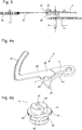
- a clock display mechanism will now be described in the following with reference in conjunction to figures 1, 2a, 2b , 3, 4a and 4b .
- the invention relates to a clockwork display mechanism 1 comprising a cam 2 arranged to be driven by a time base, at least a first means of driving a first display 3 of a first magnitude, the means of 'drive comprising a drive rake 4 mounted to pivot about an axis A and being arranged to cooperate, directly or indirectly, with a drive wheel 30 of the first display 3.
- the drive rake 4 comprises a first rigid part 40 comprising a toothed sector 41 and second elastically deformable part 42, said first rigid part 40 and second elastically deformable part 42 being separated, at the level of the axis of pivoting A, by a slot 5 receiving an eccentric 6 arranged to cooperate with said elastically deformable part 42 and move the latter away from the first rigid part 40.
- the second elastically deformable part 42 comprises at its free end a feeler 43 arranged to follow the contour of the cam 2 and a heel 44 arranged to cooperate with the eccentric 6, the rake 4 being forced against the cam 2 by means of a return spring, not shown.
- the rigid part 40 of the rake 4 comprises a notch 7 opening into the slot 5, the notch 7 being arranged to receive the eccentric 6 and hold it in position.
- the eccentric 6 comprises a foot 60 in the form of a mushroom, a first portion 601 of the foot having a diameter greater than the diameter of the second portion 602.
- the second portion 602 of the foot of the eccentric is arranged to rest in the notch 7, the first portion resting against the upper or lower face of the rigid part 40 and the eccentric 6.
- the eccentric 6 comprises a body 61 in the form of a disc offset with respect to the foot, the body 61 also resting against the upper or lower face of the rigid part 40 of the rake 4, so as to properly hold the eccentric 6 in place once the latter has been inserted into the notch 7, the first portion 601 and the body 61 each resting against one of the faces of the rigid part 40 of the rake 4.
- the eccentric 6 also has a cylindrical head 62 comprising a slot 65 to facilitate the setting in rotation and the adjustment using a tool such as a screwdriver for example.
- the eccentric is in one piece and forms one and the same part.
- Those skilled in the art could consider making it in several parts and then assembling them.
- the body 61 rests on the upper face of the rigid part 40 and is in point contact with the elastically deformable part 42, near the feeler 43.
- the body 61 of the eccentric 6 comprises notches 63 on all or part of its circumference and arranged to cooperate with the elastically deformable part, the passage from one notch to the next increasing the distance between the center of the eccentric 6 and the elastic part 42.
- the body 61 also has a flat 64 to facilitate installation of the eccentric 6 and limit the stresses on the elastically deformable part 42, the flat being placed opposite the heel 44 when inserting the eccentric 6 into the slot 5 at the level of the notch 7 .
- the eccentric 6 makes it possible to vary and adjust the opening angle ⁇ of the slot 5 and implicitly the position of the display 30, the opening angle ⁇ being between 0.08 ° and 1.04 °, one notch (or a pitch) of the eccentric corresponding to a spacing of the elastically deformable part of 0.08 °.
- the eccentric 6 When the eccentric 6 is placed in the slot 5, at the level of the notch 7, the latter exerts a prestress and opens the opening angle ⁇ by 2 ° with respect to its rest position.
- Such a configuration allows good maintenance of the eccentric 6, the latter remaining in its location following a fall of the watch from a height of 50cm.
- the cam 2 is a snail cam comprising, on its maximum radius, a beak 20, the passage of which controls a jump of the feeler 43 in return on the minimum radius of the cam.
- the profile of the cam is adapted to the trajectory that one wishes to achieve, the example above being dedicated to a retrograde display of the days.
- other profiles can be produced according to the needs of a person skilled in the art, such as a display of the hours, the date, the months, the years, the moon, etc.).
- the rigid part 40 of the rake 4 is machined near the eccentric 6 and has a lesser thickness compared to the elastically deformable part 42 so as to facilitate handling of the eccentric 6.
- a person skilled in the art could also have put in place a bore only at the level of the eccentric 6, the latter then being surrounded by a rigid part 40.
- the eccentric 6 is placed near the slot 5 firstly by orienting it so that the flat 64 is in contact with the heel 44 of the elastically deformable part 42. The operator or the user then pushes the eccentric 6 until the eccentric 6 is clipped into the notch 7 using the second portion 602 as a guide means, the elastically deformable part 42 exerting a force on the eccentric 6 and holding it in place in the notch 7.
- the mechanism is then mounted on a bridge, a plate of a watch movement, and the adjustment of the first display 3 can be carried out if necessary.
- the operator rotates the eccentric 6 via the head 62 by means of a screwdriver, the notches 63 allowing fine adjustment and a better feeling for the operator.
- the body 61 acts on the part elastically deformable 42 by causing it to move relative to the axis A and increases the opening angle ⁇ of the slot 5, which has the effect of modifying the position of the driving wheel 30 and ultimately of the display 3.
- the operator can leave the eccentric 6 in position, the notches 63 and the heel 44 making it possible to maintain the eccentric in its position.
- the rake and the eccentric are made of a metal or metal alloy but could equally well be made of silicon, ceramic or composite materials, for example.
- the display mechanism is a retrograde display.
- the invention relates to a timepiece movement comprising at least one such display mechanism 1.
- the invention also relates to a watch comprising such a clockwork movement, and / or comprising at least one such display mechanism 1.
Landscapes
- Physics & Mathematics (AREA)
- General Physics & Mathematics (AREA)
- Geometry (AREA)
- Electromechanical Clocks (AREA)
- Electric Clocks (AREA)
- Transmission Devices (AREA)
- Instrument Panels (AREA)
Abstract
Description
- La présente invention se rapporte au domaine de l'horlogerie ou de la bijouterie. Elle concerne plus précisément un mécanisme d'affichage d'horlogerie.
- Traditionnellement, les mécanismes standards d'affichage comprennent une aiguille d'affichage ou un disque et un guichet pour afficher une information. L'aiguille ou le disque peuvent être directement rivetés sur un pignon ou une roue dentée par exemple.
- Une fois l'affichage mis en place, il est alors difficile, voire impossible, de réaliser une indexation de ce dernier et d'ajuster sa position après assemblage.
- Un but de la présente invention est de pallier tout ou partie des inconvénients cités précédemment en fournissant un mécanisme de d'affichage permettant de régler la position de l'afficheur indépendamment de son assemblage et restant ajustable après assemblage.
- L'invention a aussi pour but de fournir un mécanisme d'affichage permettant un ajustage en tout temps pour compenser l'usure de certains composants du mécanisme d'affichage.
- L'invention a également pour but de fournir un mécanisme d'affichage présentant un faible encombrement, de conception simple et économique à fabriquer.
- A cet effet, l'invention se rapporte à un mécanisme d'affichage d'horlogerie comprenant une came agencée pour être entrainée par une base de temps, et au moins un premier moyen d'entrainement d'un premier afficheur d'une première grandeur, ledit moyen d'entrainement comprenant un râteau d'entrainement pivotant autour d'un axe A et étant agencé pour coopérer, directement ou indirectement, avec un mobile d'entrainement dudit premier afficheur, ledit râteau d'entrainement comprenant une première partie rigide comprenant un secteur denté et une deuxième partie déformable élastiquement, lesdites première partie rigide et deuxième partie déformable élastiquement étant séparée par une fente recevant un excentrique agencé pour coopérer avec ladite partie déformable élastiquement et écarter cette dernière de la première partie rigide.
- Conformément à d'autres variantes avantageuses de l'invention :
- la deuxième partie déformable élastiquement comprend un palpeur agencé pour suivre le contour de la came ;
- la partie rigide comprend une encoche débouchant dans la fente, agencée pour recevoir ledit excentrique ;
- ledit excentrique présente un pied de forme cylindrique reposant dans l'encoche, un corps sous la forme d'un disque décentré par rapport audit pied, et d'une tête de forme cylindrique, le corps reposant sur la partie rigide et étant en contact ponctuel avec la partie déformable élastiquement ;
- le corps de l'excentrique comprend des crans sur tout ou partie de son pourtour et un méplat, les crans étant agencés pour coopérer avec ladite partie déformable élastiquement ;
- la fente présente un angle d'ouverture α compris entre 0.08° et 1.04°, l'angle d'ouverture α étant réglé au moyen de l'excentrique ;
- la came est une came limaçon comprenant, sur son rayon maximal, un bec dont le passage commande un saut du palpeur en retour sur le rayon minimal de la came ;
- ladite partie déformable présente une épaisseur plus élevée que celle de la partie rigide ;
- le mécanisme d'affichage est rétrograde.
- L'invention concerne également un mouvement d'horlogerie comprenant au moins un mécanisme d'affichage conforme à l'invention et une montre comprenant un tel mouvement d'horlogerie et/ou un tel mécanisme d'affichage.
- D'autres caractéristiques et avantages de la présente invention ressortiront plus clairement de la description détaillée qui suit d'un exemple de réalisation d'un mécanisme d'affichage d'horlogerie selon l'invention, cet exemple étant donné à titre purement illustratif et non limitatif seulement, en liaison avec le dessin annexé sur lequel :
- la
figure 1 illustre une vue en perspective d'un mécanisme d'affichage selon l'invention ; - les
figures 2a et 2b représentent respectivement une vue de dessus et une vue de dessous d'un mécanisme d'affichage selon l'invention; - la
figure 3 illustre une vue de face d'un mécanisme d'affichage selon l'invention, et - les
figure 4a et 4b illustrent respectivement une vue en perspective d'un râteau et d'un excentrique d'un mécanisme d'affichage selon l'invention. - Un mécanisme d'affichage d'horlogerie va maintenant être décrit dans ce qui suit faisant référence conjointement aux
figures 1, 2a, 2b ,3, 4a et 4b . - L'invention concerne un mécanisme d'affichage 1 d'horlogerie comprenant une came 2 agencée pour être entrainée par une base de temps, au moins un premier moyen d'entrainement d'un premier afficheur 3 d'une première grandeur, le moyen d'entrainement comprenant un râteau d'entrainement 4 monté pivotant autour d'un axe A et étant agencé pour coopérer, directement ou indirectement, avec un mobile d'entrainement 30 du premier afficheur 3.
- Selon l'invention, le râteau d'entrainement 4 comprend une première partie rigide 40 comprenant un secteur denté 41 et deuxième partie déformable élastiquement 42, lesdites première partie rigide 40 et deuxième partie déformable élastiquement 42 étant séparée, au niveau de l'axe de pivotement A, par une fente 5 recevant un excentrique 6 agencé pour coopérer avec ladite partie déformable élastiquement 42 et écarter cette dernière de la première partie rigide 40.
- La deuxième partie déformable élastiquement 42 comprend à son extrémité libre un palpeur 43 agencé pour suivre le contour de la came 2 et un talon 44 agencé pour coopérer avec l'excentrique 6, le râteau 4 étant contraint contre la came 2 par le biais d'un ressort de rappel non représenté.
- Comme on peut l'observer à la
figure 4a , la partie rigide 40 du râteau 4 comprend une encoche 7 débouchant dans la fente 5, l'encoche 7 étant agencée pour recevoir l'excentrique 6 et le maintenir en position. - Tel qu'illustré la
figure 4b , l'excentrique 6 comprend un pied 60 en forme de champignon, une première portion 601 du pied présentant un diamètre supérieur au diamètre de la deuxième portion 602. La deuxième portion 602 du pied de l'excentrique est agencée pour reposer dans l'encoche 7, la première portion reposant contre la face supérieure ou inférieure de la partie rigide 40 et l'excentrique 6. L'excentrique 6 comprend un corps 61 sous la forme d'un disque décentré par rapport au pied, le corps 61 reposant également contre la face supérieure ou inférieure de la partie rigide 40 du râteau 4, de manière à bien maintenir l'excentrique 6 en place une fois ce dernier inséré dans l'encoche 7, la première portion 601 et le corps 61 reposant chacun contre l'une des faces de la partie rigide 40 du râteau 4. - Avantageusement, l'excentrique 6 présente également une tête 62 de forme cylindrique comprenant une fente 65 pour faciliter la mise en rotation et le réglage à l'aide d'un outil tel qu'un tournevis par exemple.
- Selon un mode de réalisation de l'invention l'excentrique est monobloc et forme une seule et même pièce. L'homme du métier pourrait envisager de le réaliser en plusieurs parties puis de les assembler.
- Comme on peut l'observer à la
figure 1 , le corps 61 repose sur la face supérieure de la partie rigide 40 et est en contact ponctuel avec la partie déformable élastiquement 42, à proximité du palpeur 43. Le corps 61 de l'excentrique 6 comprend des crans 63 sur tout ou partie de son pourtour et agencés pour coopérer avec la partie déformable élastiquement, le passage d'un cran au suivant augmentant la distance entre le centre de l'excentrique 6 et la partie élastique 42. Le corps 61 présente également un méplat 64 pour faciliter la mise en place de l'excentrique 6 et limiter les contraintes sur la partie déformable élastiquement 42, le méplat étant placé en vis-à-vis du talon 44 lors de l'insertion de l'excentrique 6 dans la fente 5 au niveau de l'encoche 7. - L'excentrique 6 permet de faire varier et de régler l'angle d'ouverture α de la fente 5 et implicitement la position de l'afficheur 30, l'angle d'ouverture α étant compris entre 0.08° et 1.04°, un cran (ou un pas) de l'excentrique correspondant à un écartement de la partie déformable élastiquement de 0.08°. Lors de la mise en place de l'excentrique 6 dans la fente 5, au niveau de l'encoche 7, ce dernier exerce une précontrainte et ouvre l'angle d'ouverture α de 2° par rapport à sa position de repos. Une telle configuration permet un bon maintien de l'excentrique 6, ce dernier restant dans son emplacement suite à une chute de la montre depuis une hauteur de 50cm.
- Dans un mode de réalisation de l'invention, la came 2 est une came limaçon comprenant, sur son rayon maximal, un bec 20 dont le passage commande un saut du palpeur 43 en retour sur le rayon minimal de la came. Le profil de la came est adapté à la trajectoire qu'on souhaite réaliser, l'exemple ci-dessus étant dédié à un affichage rétrograde des jours. Naturellement, d'autres profils sont réalisables en fonction des besoins de l'homme du métier, tel qu'un affichage des heures, de la date, des mois, des années, de la lune, etc...).
- Comme on peut l'observer sur les figures, la partie rigide 40 du râteau 4 est usinée à proximité de l'excentrique 6 et présente une épaisseur moindre par rapport à la partie déformable élastiquement 42 de façon à faciliter la manipulation de l'excentrique 6. L'homme du métier aurait également pu mettre en place un alésage uniquement au niveau de l'excentrique 6, ce dernier étant alors entouré par une partie rigide 40.
- Pour mettre en place l'excentrique 6 dans la fente 5 comme illustré aux
figures 1 à 3 , on place l'excentrique 6 à proximité de la fente 5 dans un premier temps en l'orientant de manière que le méplat 64 soit en contact avec le talon 44 de la partie déformable élastiquement 42. L'opérateur ou l'utilisateur pousse ensuite l'excentrique 6 jusqu'à clipper l'excentrique 6 dans l'encoche 7 en utilisant la deuxième portion 602 comme moyen de guidage, la partie déformable élastiquement 42 exerçant une force sur l'excentrique 6 et le maintenant en place dans l'encoche 7. - Le mécanisme est ensuite monté sur un pont une platine d'un mouvement horloger, et le réglage du premier afficheur 3 peut être effectué si besoin. Dans le cas où l'opérateur doit modifier de l'afficheur 3, l'opérateur fait pivoter l'excentrique 6 via la tête 62 au moyen d'un tournevis, les crans 63 permettant un réglage fin et une meilleure ressenti pour l'opérateur. Lorsque l'opérateur fait pivoter l'excentrique 6, le corps 61 agit sur la partie déformable élastiquement 42 en la faisant se déplacer par rapport à l'axe A et augmente l'angle d'ouverture α de la fente 5, ce qui a pour effet de modifier la position du mobile d'entrainement 30 et au final de l'afficheur 3.
- Une fois la position réglée, l'opérateur peut laisser l'excentrique 6 en position, les crans 63 et le talon 44 permettant de maintenir l'excentrique dans sa position.
- Dans le mode de réalisation précédemment décrit, le râteau et l'excentrique sont réalisés en un métal ou alliage métallique mais pourrait aussi bien être réalisés en silicium, en céramique ou en matériaux composites par exemple.
- Selon l'invention, le mécanisme d'affichage est un affichage rétrograde.
- L'invention concerne un mouvement d'horlogerie comportant au moins un tel mécanisme d'affichage 1.
- L'invention concerne encore une montre comportant un tel mouvement d'horlogerie, et/ou comportant au moins un tel mécanisme d'affichage 1.
- Grâce à ces différents aspects de l'invention, on dispose d'un mécanisme d'affichage réglable facilement et rapide, et cela indépendamment de son assemblage.
- Bien entendu, la présente invention ne se limite pas à l'exemple illustré et est susceptible de diverses variantes et modifications qui apparaîtront à l'homme de l'art.
Claims (11)
- Mécanisme d'affichage (1) d'horlogerie comprenant une came (2) agencée pour être entrainée par une base de temps, au moins un premier moyen d'entrainement d'un premier afficheur (3) d'une première grandeur, ledit moyen d'entrainement comprenant un râteau d'entrainement (4) pivotant autour d'un axe A et étant agencé pour coopérer, directement ou indirectement, avec un mobile d'entrainement (30) dudit premier afficheur (3), ledit râteau d'entrainement (4) comprenant une première partie rigide (40) comprenant un secteur denté (41) et deuxième partie déformable élastiquement (42), lesdites première partie rigide (40) et deuxième partie déformable élastiquement (42) étant séparée par une fente (5) recevant un excentrique (6) agencé pour coopérer avec ladite partie déformable élastiquement (42) et écarter cette dernière de la première partie rigide (40).
- Mécanisme d'affichage (1) d'horlogerie selon la revendication 1, caractérisé en ce que la deuxième partie déformable élastiquement (42) comprend un palpeur (43) agencé pour suivre le contour de la came (2).
- Mécanisme d'affichage (1) d'horlogerie selon la revendication 1 ou 2, dans lequel la partie rigide (40) comprend une encoche (7) débouchant dans la fente (5), agencée pour recevoir ledit excentrique (6).
- Mécanisme d'affichage (1) d'horlogerie selon l'une des revendications 1 à 3, dans lequel ledit excentrique (6) présente successivement un pied (60) reposant dans l'encoche (7), un corps (61) sous la forme d'un disque décentré par rapport audit pied, et d'une tête (62) de forme cylindrique, le corps (61) reposant sur la partie rigide (40) et étant en contact ponctuel avec la partie déformable élastiquement (42).
- Mécanisme d'affichage (1) d'horlogerie selon la revendication 4, dans lequel le corps (61) de l'excentrique (6) comprend des crans (63) sur tout ou partie de son pourtour et un méplat (64), les crans étant agencés pour coopérer avec ladite partie déformable élastiquement.
- Mécanisme d'affichage (1) d'horlogerie selon l'une des revendications 1 à 5, dans lequel la fente (5) présente un angle d'ouverture α compris entre 0.08° et 1.04° (à confirmer/préciser), l'angle d'ouverture α étant réglé au moyen de l'excentrique (6).
- Mécanisme d'affichage (1) d'horlogerie selon la revendication 6, dans lequel la came (2) est une came limaçon comprenant, sur son rayon maximal, un bec (20) dont le passage commande un saut du palpeur (43) en retour sur le rayon minimal de la came.
- Mécanisme d'affichage (1) d'horlogerie selon la revendication 1 ou 2, dans lequel ladite partie déformable présente une épaisseur plus élevée que celle de la partie rigide.
- Mécanisme d'affichage (1) d'horlogerie selon l'une des revendications 1 à 8, caractérisé en ce que le mécanisme d'affichage est rétrograde.
- Mouvement d'horlogerie comprenant au moins un mécanisme d'affichage (1) selon l'une des revendications 1 à 9.
- Montre comprenant un mouvement d'horlogerie selon la revendication 10, et/ou comprenant et mécanisme d'affichage (1) selon l'une des revendications 1 à 9.
Priority Applications (4)
| Application Number | Priority Date | Filing Date | Title |
|---|---|---|---|
| EP20158326.7A EP3869280B1 (fr) | 2020-02-19 | 2020-02-19 | Mecanisme d'affichage d'horlogerie |
| US17/128,687 US11586149B2 (en) | 2020-02-19 | 2020-12-21 | Horological display mechanism |
| JP2021003317A JP6997349B2 (ja) | 2020-02-19 | 2021-01-13 | 計時器用表示機構 |
| CN202110189252.3A CN113281981B (zh) | 2020-02-19 | 2021-02-19 | 钟表显示机构 |
Applications Claiming Priority (1)
| Application Number | Priority Date | Filing Date | Title |
|---|---|---|---|
| EP20158326.7A EP3869280B1 (fr) | 2020-02-19 | 2020-02-19 | Mecanisme d'affichage d'horlogerie |
Publications (2)
| Publication Number | Publication Date |
|---|---|
| EP3869280A1 true EP3869280A1 (fr) | 2021-08-25 |
| EP3869280B1 EP3869280B1 (fr) | 2024-04-17 |
Family
ID=69713940
Family Applications (1)
| Application Number | Title | Priority Date | Filing Date |
|---|---|---|---|
| EP20158326.7A Active EP3869280B1 (fr) | 2020-02-19 | 2020-02-19 | Mecanisme d'affichage d'horlogerie |
Country Status (4)
| Country | Link |
|---|---|
| US (1) | US11586149B2 (fr) |
| EP (1) | EP3869280B1 (fr) |
| JP (1) | JP6997349B2 (fr) |
| CN (1) | CN113281981B (fr) |
Cited By (2)
| Publication number | Priority date | Publication date | Assignee | Title |
|---|---|---|---|---|
| EP4307052A1 (fr) * | 2022-07-14 | 2024-01-17 | Manufacture d'Horlogerie Audemars Piguet SA | Mecanisme de chronographe pour mouvement horloger |
| CH720028A1 (fr) * | 2022-09-12 | 2024-03-28 | Patek Philippe Sa Geneve | Mouvement horloger comprenant un dispositif de reglage de la position d'un organe d'affichage et procede de reglage |
Citations (2)
| Publication number | Priority date | Publication date | Assignee | Title |
|---|---|---|---|---|
| EP2784603A1 (fr) * | 2013-03-28 | 2014-10-01 | Rolex Sa | Dispositif d'affichage d'une information temporelle |
| CH712165A2 (fr) * | 2016-02-18 | 2017-08-31 | Blancpain Sa | Affichage d'horlogerie à aiguille rétractable. |
Family Cites Families (16)
| Publication number | Priority date | Publication date | Assignee | Title |
|---|---|---|---|---|
| DE4012026A1 (de) * | 1990-04-13 | 1991-10-17 | Int Watch Co Iwc | Anschlagvorrichtung |
| CH691833A5 (fr) * | 1997-09-25 | 2001-10-31 | Vacheron & Constantin S A | Module d'affichage pour pièce d'horlogerie, notamment montre-bracelet, comportant un affichage sautant des heures et un affichage rétrograde des minutes. |
| CN100478578C (zh) * | 2005-10-06 | 2009-04-15 | 精工爱普生株式会社 | 调速装置及使用该调速装置的发电装置、设备 |
| EP1936447A2 (fr) * | 2006-12-20 | 2008-06-25 | Franck Müller Watchland SA | Mécanisme d'affichage irrégulier pour pièce d'horlogerie |
| JP2011128027A (ja) * | 2009-12-18 | 2011-06-30 | Techno Ark Co Ltd | 暦時計 |
| CH705782A2 (fr) * | 2011-11-17 | 2013-05-31 | Blancpain Sa | Dispositif mécanique indicateur de changement d'état pour un mécanisme d'affichage semi-instantané ou instantané par sauts. |
| CH707233A1 (de) * | 2012-11-22 | 2014-05-30 | Eterna Ag Uhrenfabrik | Minutzenzähler einer Uhr, insbesondere eines Chronographen. |
| JP6029441B2 (ja) * | 2012-12-10 | 2016-11-24 | セイコーインスツル株式会社 | 時計用カレンダ機構並びに該機構を備えたムーブメント及びカレンダ時計 |
| EP2824521B1 (fr) * | 2013-07-12 | 2025-03-26 | Rolex Sa | Mécanisme horloger, mouvement horloger et pièce d'horlogerie |
| CH711184B1 (fr) * | 2015-06-12 | 2019-04-15 | Chanel Sa Geneve | Mouvement de montre comportant un mécanisme de correction rapide de l'heure courante. |
| EP3208665B1 (fr) * | 2016-02-18 | 2019-01-02 | Blancpain SA. | Affichage retrograde d'horlogerie a aiguille retractable |
| CH712217A2 (fr) * | 2016-03-15 | 2017-09-15 | Chanel Sa Genève | Mouvement de montre comportant un affichage rétrograde et un anneau des heures sautant. |
| EP3410231B1 (fr) * | 2017-05-29 | 2021-06-30 | Montres Breguet S.A. | Mécanisme d'horlogerie |
| CH714458B1 (fr) * | 2017-12-19 | 2022-03-31 | Omega Sa | Mécanisme d'affichage sonore et pièce d'horlogerie comportant un tel mécanisme d'affichage sonore. |
| EP3637197B1 (fr) * | 2018-10-12 | 2021-05-19 | Blancpain SA | Dispositif de reglage d'un affichage retrograde d'horlogerie |
| EP3832397B1 (fr) * | 2019-12-05 | 2023-09-06 | Blancpain SA | Mecanisme d'affichage d'horlogerie a saut instantane |
-
2020
- 2020-02-19 EP EP20158326.7A patent/EP3869280B1/fr active Active
- 2020-12-21 US US17/128,687 patent/US11586149B2/en active Active
-
2021
- 2021-01-13 JP JP2021003317A patent/JP6997349B2/ja active Active
- 2021-02-19 CN CN202110189252.3A patent/CN113281981B/zh active Active
Patent Citations (2)
| Publication number | Priority date | Publication date | Assignee | Title |
|---|---|---|---|---|
| EP2784603A1 (fr) * | 2013-03-28 | 2014-10-01 | Rolex Sa | Dispositif d'affichage d'une information temporelle |
| CH712165A2 (fr) * | 2016-02-18 | 2017-08-31 | Blancpain Sa | Affichage d'horlogerie à aiguille rétractable. |
Cited By (3)
| Publication number | Priority date | Publication date | Assignee | Title |
|---|---|---|---|---|
| EP4307052A1 (fr) * | 2022-07-14 | 2024-01-17 | Manufacture d'Horlogerie Audemars Piguet SA | Mecanisme de chronographe pour mouvement horloger |
| WO2024013346A1 (fr) * | 2022-07-14 | 2024-01-18 | Manufacture D'horlogerie Audemars Piguet Sa | Mecanisme pour la mesure d'un temps pour mouvement horloger, notamment mecanisme de chronographe |
| CH720028A1 (fr) * | 2022-09-12 | 2024-03-28 | Patek Philippe Sa Geneve | Mouvement horloger comprenant un dispositif de reglage de la position d'un organe d'affichage et procede de reglage |
Also Published As
| Publication number | Publication date |
|---|---|
| US20210255585A1 (en) | 2021-08-19 |
| JP6997349B2 (ja) | 2022-01-17 |
| EP3869280B1 (fr) | 2024-04-17 |
| CN113281981B (zh) | 2022-08-19 |
| US11586149B2 (en) | 2023-02-21 |
| CN113281981A (zh) | 2021-08-20 |
| JP2021131380A (ja) | 2021-09-09 |
Similar Documents
| Publication | Publication Date | Title |
|---|---|---|
| EP2977829B1 (fr) | Ensemble à mobile de freinage d'horlogerie | |
| EP3483663B1 (fr) | Dispositif d'entraînement pour système de calendrier horloger | |
| EP3869280B1 (fr) | Mecanisme d'affichage d'horlogerie | |
| WO2004070478A2 (fr) | Masse oscillante | |
| EP4194964B1 (fr) | Balancier à reglage d'inertie | |
| EP2977833B1 (fr) | Positionnement précis de pont d'horlogerie | |
| WO2016030257A1 (fr) | Ensemble balancier-spiral d'horlogerie | |
| EP1890203A1 (fr) | Boîte de montre comprenant un fond et procédé de fixation d'un fond sur une boîte de montre | |
| CH717151A2 (fr) | Mécanisme d'affichage d'horlogerie. | |
| EP0640892B1 (fr) | Pièce d'horlogerie | |
| EP1923754B1 (fr) | Mouvement d'horlogerie équipé d'un module d'affichage | |
| EP2506093A1 (fr) | Balancier pour mouvement d'horlogerie | |
| EP4428624B1 (fr) | Dispositif de reglage autonome de la longueur active d'un spiral | |
| EP2444860A1 (fr) | Mécanisme régulateur pour pièce d'horlogerie | |
| WO2017102845A1 (fr) | Système oscillant pour montre | |
| EP3923084B1 (fr) | Systeme d'anticorrection d'un indicateur pour une piece d'horlogerie | |
| FR3090912A1 (fr) | Remontoir a systeme pare-chocs | |
| EP4428626B1 (fr) | Dispositif de reglage autonome de la longueur active d'un spiral | |
| EP4428628B1 (fr) | Dispositif de reglage autonome de la longueur active d'un spiral | |
| EP4123391B1 (fr) | Composant horloger a fixer sur un arbre et son procédé d'assemblage | |
| EP4575657A1 (fr) | Dispositif de mise à l'heure d'un mouvement horloger | |
| EP1925996A1 (fr) | Dispositif de correction d'un mécanisme d'affichage pour pièce d'horlogerie | |
| CH717517A2 (fr) | Système d'anticorrection d'un indicateur pour une pièce d'horlogerie. | |
| EP2689294B1 (fr) | Sautoir, mouvement horloger et piece d'horlogerie equipes d'un tel sautoir | |
| CH719047A2 (fr) | Mécanisme d'entraînement discontinu d'horlogerie. |
Legal Events
| Date | Code | Title | Description |
|---|---|---|---|
| PUAI | Public reference made under article 153(3) epc to a published international application that has entered the european phase |
Free format text: ORIGINAL CODE: 0009012 |
|
| STAA | Information on the status of an ep patent application or granted ep patent |
Free format text: STATUS: THE APPLICATION HAS BEEN PUBLISHED |
|
| AK | Designated contracting states |
Kind code of ref document: A1 Designated state(s): AL AT BE BG CH CY CZ DE DK EE ES FI FR GB GR HR HU IE IS IT LI LT LU LV MC MK MT NL NO PL PT RO RS SE SI SK SM TR |
|
| STAA | Information on the status of an ep patent application or granted ep patent |
Free format text: STATUS: REQUEST FOR EXAMINATION WAS MADE |
|
| 17P | Request for examination filed |
Effective date: 20220225 |
|
| RBV | Designated contracting states (corrected) |
Designated state(s): AL AT BE BG CH CY CZ DE DK EE ES FI FR GB GR HR HU IE IS IT LI LT LU LV MC MK MT NL NO PL PT RO RS SE SI SK SM TR |
|
| P01 | Opt-out of the competence of the unified patent court (upc) registered |
Effective date: 20230611 |
|
| GRAP | Despatch of communication of intention to grant a patent |
Free format text: ORIGINAL CODE: EPIDOSNIGR1 |
|
| STAA | Information on the status of an ep patent application or granted ep patent |
Free format text: STATUS: GRANT OF PATENT IS INTENDED |
|
| INTG | Intention to grant announced |
Effective date: 20231206 |
|
| GRAJ | Information related to disapproval of communication of intention to grant by the applicant or resumption of examination proceedings by the epo deleted |
Free format text: ORIGINAL CODE: EPIDOSDIGR1 |
|
| STAA | Information on the status of an ep patent application or granted ep patent |
Free format text: STATUS: REQUEST FOR EXAMINATION WAS MADE |
|
| GRAS | Grant fee paid |
Free format text: ORIGINAL CODE: EPIDOSNIGR3 |
|
| STAA | Information on the status of an ep patent application or granted ep patent |
Free format text: STATUS: GRANT OF PATENT IS INTENDED |
|
| GRAP | Despatch of communication of intention to grant a patent |
Free format text: ORIGINAL CODE: EPIDOSNIGR1 |
|
| INTC | Intention to grant announced (deleted) | ||
| GRAA | (expected) grant |
Free format text: ORIGINAL CODE: 0009210 |
|
| STAA | Information on the status of an ep patent application or granted ep patent |
Free format text: STATUS: THE PATENT HAS BEEN GRANTED |
|
| INTG | Intention to grant announced |
Effective date: 20240307 |
|
| AK | Designated contracting states |
Kind code of ref document: B1 Designated state(s): AL AT BE BG CH CY CZ DE DK EE ES FI FR GB GR HR HU IE IS IT LI LT LU LV MC MK MT NL NO PL PT RO RS SE SI SK SM TR |
|
| REG | Reference to a national code |
Ref country code: GB Ref legal event code: FG4D Free format text: NOT ENGLISH |
|
| REG | Reference to a national code |
Ref country code: CH Ref legal event code: EP |
|
| REG | Reference to a national code |
Ref country code: DE Ref legal event code: R096 Ref document number: 602020028998 Country of ref document: DE |
|
| REG | Reference to a national code |
Ref country code: IE Ref legal event code: FG4D Free format text: LANGUAGE OF EP DOCUMENT: FRENCH |
|
| REG | Reference to a national code |
Ref country code: LT Ref legal event code: MG9D |
|
| REG | Reference to a national code |
Ref country code: NL Ref legal event code: MP Effective date: 20240417 |
|
| REG | Reference to a national code |
Ref country code: AT Ref legal event code: MK05 Ref document number: 1677826 Country of ref document: AT Kind code of ref document: T Effective date: 20240417 |
|
| PG25 | Lapsed in a contracting state [announced via postgrant information from national office to epo] |
Ref country code: NL Free format text: LAPSE BECAUSE OF FAILURE TO SUBMIT A TRANSLATION OF THE DESCRIPTION OR TO PAY THE FEE WITHIN THE PRESCRIBED TIME-LIMIT Effective date: 20240417 |
|
| PG25 | Lapsed in a contracting state [announced via postgrant information from national office to epo] |
Ref country code: NL Free format text: LAPSE BECAUSE OF FAILURE TO SUBMIT A TRANSLATION OF THE DESCRIPTION OR TO PAY THE FEE WITHIN THE PRESCRIBED TIME-LIMIT Effective date: 20240417 |
|
| PG25 | Lapsed in a contracting state [announced via postgrant information from national office to epo] |
Ref country code: IS Free format text: LAPSE BECAUSE OF FAILURE TO SUBMIT A TRANSLATION OF THE DESCRIPTION OR TO PAY THE FEE WITHIN THE PRESCRIBED TIME-LIMIT Effective date: 20240817 |
|
| PG25 | Lapsed in a contracting state [announced via postgrant information from national office to epo] |
Ref country code: BG Free format text: LAPSE BECAUSE OF FAILURE TO SUBMIT A TRANSLATION OF THE DESCRIPTION OR TO PAY THE FEE WITHIN THE PRESCRIBED TIME-LIMIT Effective date: 20240417 |
|
| PG25 | Lapsed in a contracting state [announced via postgrant information from national office to epo] |
Ref country code: HR Free format text: LAPSE BECAUSE OF FAILURE TO SUBMIT A TRANSLATION OF THE DESCRIPTION OR TO PAY THE FEE WITHIN THE PRESCRIBED TIME-LIMIT Effective date: 20240417 Ref country code: FI Free format text: LAPSE BECAUSE OF FAILURE TO SUBMIT A TRANSLATION OF THE DESCRIPTION OR TO PAY THE FEE WITHIN THE PRESCRIBED TIME-LIMIT Effective date: 20240417 |
|
| PG25 | Lapsed in a contracting state [announced via postgrant information from national office to epo] |
Ref country code: GR Free format text: LAPSE BECAUSE OF FAILURE TO SUBMIT A TRANSLATION OF THE DESCRIPTION OR TO PAY THE FEE WITHIN THE PRESCRIBED TIME-LIMIT Effective date: 20240718 |
|
| PG25 | Lapsed in a contracting state [announced via postgrant information from national office to epo] |
Ref country code: PT Free format text: LAPSE BECAUSE OF FAILURE TO SUBMIT A TRANSLATION OF THE DESCRIPTION OR TO PAY THE FEE WITHIN THE PRESCRIBED TIME-LIMIT Effective date: 20240819 |
|
| PG25 | Lapsed in a contracting state [announced via postgrant information from national office to epo] |
Ref country code: ES Free format text: LAPSE BECAUSE OF FAILURE TO SUBMIT A TRANSLATION OF THE DESCRIPTION OR TO PAY THE FEE WITHIN THE PRESCRIBED TIME-LIMIT Effective date: 20240417 |
|
| PG25 | Lapsed in a contracting state [announced via postgrant information from national office to epo] |
Ref country code: AT Free format text: LAPSE BECAUSE OF FAILURE TO SUBMIT A TRANSLATION OF THE DESCRIPTION OR TO PAY THE FEE WITHIN THE PRESCRIBED TIME-LIMIT Effective date: 20240417 |
|
| PG25 | Lapsed in a contracting state [announced via postgrant information from national office to epo] |
Ref country code: PL Free format text: LAPSE BECAUSE OF FAILURE TO SUBMIT A TRANSLATION OF THE DESCRIPTION OR TO PAY THE FEE WITHIN THE PRESCRIBED TIME-LIMIT Effective date: 20240417 |
|
| PG25 | Lapsed in a contracting state [announced via postgrant information from national office to epo] |
Ref country code: LV Free format text: LAPSE BECAUSE OF FAILURE TO SUBMIT A TRANSLATION OF THE DESCRIPTION OR TO PAY THE FEE WITHIN THE PRESCRIBED TIME-LIMIT Effective date: 20240417 |
|
| PG25 | Lapsed in a contracting state [announced via postgrant information from national office to epo] |
Ref country code: PT Free format text: LAPSE BECAUSE OF FAILURE TO SUBMIT A TRANSLATION OF THE DESCRIPTION OR TO PAY THE FEE WITHIN THE PRESCRIBED TIME-LIMIT Effective date: 20240819 Ref country code: PL Free format text: LAPSE BECAUSE OF FAILURE TO SUBMIT A TRANSLATION OF THE DESCRIPTION OR TO PAY THE FEE WITHIN THE PRESCRIBED TIME-LIMIT Effective date: 20240417 Ref country code: NO Free format text: LAPSE BECAUSE OF FAILURE TO SUBMIT A TRANSLATION OF THE DESCRIPTION OR TO PAY THE FEE WITHIN THE PRESCRIBED TIME-LIMIT Effective date: 20240717 Ref country code: LV Free format text: LAPSE BECAUSE OF FAILURE TO SUBMIT A TRANSLATION OF THE DESCRIPTION OR TO PAY THE FEE WITHIN THE PRESCRIBED TIME-LIMIT Effective date: 20240417 Ref country code: IS Free format text: LAPSE BECAUSE OF FAILURE TO SUBMIT A TRANSLATION OF THE DESCRIPTION OR TO PAY THE FEE WITHIN THE PRESCRIBED TIME-LIMIT Effective date: 20240817 Ref country code: HR Free format text: LAPSE BECAUSE OF FAILURE TO SUBMIT A TRANSLATION OF THE DESCRIPTION OR TO PAY THE FEE WITHIN THE PRESCRIBED TIME-LIMIT Effective date: 20240417 Ref country code: GR Free format text: LAPSE BECAUSE OF FAILURE TO SUBMIT A TRANSLATION OF THE DESCRIPTION OR TO PAY THE FEE WITHIN THE PRESCRIBED TIME-LIMIT Effective date: 20240718 Ref country code: FI Free format text: LAPSE BECAUSE OF FAILURE TO SUBMIT A TRANSLATION OF THE DESCRIPTION OR TO PAY THE FEE WITHIN THE PRESCRIBED TIME-LIMIT Effective date: 20240417 Ref country code: ES Free format text: LAPSE BECAUSE OF FAILURE TO SUBMIT A TRANSLATION OF THE DESCRIPTION OR TO PAY THE FEE WITHIN THE PRESCRIBED TIME-LIMIT Effective date: 20240417 Ref country code: BG Free format text: LAPSE BECAUSE OF FAILURE TO SUBMIT A TRANSLATION OF THE DESCRIPTION OR TO PAY THE FEE WITHIN THE PRESCRIBED TIME-LIMIT Effective date: 20240417 Ref country code: AT Free format text: LAPSE BECAUSE OF FAILURE TO SUBMIT A TRANSLATION OF THE DESCRIPTION OR TO PAY THE FEE WITHIN THE PRESCRIBED TIME-LIMIT Effective date: 20240417 Ref country code: RS Free format text: LAPSE BECAUSE OF FAILURE TO SUBMIT A TRANSLATION OF THE DESCRIPTION OR TO PAY THE FEE WITHIN THE PRESCRIBED TIME-LIMIT Effective date: 20240717 |
|
| PG25 | Lapsed in a contracting state [announced via postgrant information from national office to epo] |
Ref country code: DK Free format text: LAPSE BECAUSE OF FAILURE TO SUBMIT A TRANSLATION OF THE DESCRIPTION OR TO PAY THE FEE WITHIN THE PRESCRIBED TIME-LIMIT Effective date: 20240417 |
|
| REG | Reference to a national code |
Ref country code: DE Ref legal event code: R097 Ref document number: 602020028998 Country of ref document: DE |
|
| PG25 | Lapsed in a contracting state [announced via postgrant information from national office to epo] |
Ref country code: EE Free format text: LAPSE BECAUSE OF FAILURE TO SUBMIT A TRANSLATION OF THE DESCRIPTION OR TO PAY THE FEE WITHIN THE PRESCRIBED TIME-LIMIT Effective date: 20240417 |
|
| PG25 | Lapsed in a contracting state [announced via postgrant information from national office to epo] |
Ref country code: CZ Free format text: LAPSE BECAUSE OF FAILURE TO SUBMIT A TRANSLATION OF THE DESCRIPTION OR TO PAY THE FEE WITHIN THE PRESCRIBED TIME-LIMIT Effective date: 20240417 |
|
| PG25 | Lapsed in a contracting state [announced via postgrant information from national office to epo] |
Ref country code: SK Free format text: LAPSE BECAUSE OF FAILURE TO SUBMIT A TRANSLATION OF THE DESCRIPTION OR TO PAY THE FEE WITHIN THE PRESCRIBED TIME-LIMIT Effective date: 20240417 Ref country code: RO Free format text: LAPSE BECAUSE OF FAILURE TO SUBMIT A TRANSLATION OF THE DESCRIPTION OR TO PAY THE FEE WITHIN THE PRESCRIBED TIME-LIMIT Effective date: 20240417 |
|
| PG25 | Lapsed in a contracting state [announced via postgrant information from national office to epo] |
Ref country code: SM Free format text: LAPSE BECAUSE OF FAILURE TO SUBMIT A TRANSLATION OF THE DESCRIPTION OR TO PAY THE FEE WITHIN THE PRESCRIBED TIME-LIMIT Effective date: 20240417 |
|
| PG25 | Lapsed in a contracting state [announced via postgrant information from national office to epo] |
Ref country code: SM Free format text: LAPSE BECAUSE OF FAILURE TO SUBMIT A TRANSLATION OF THE DESCRIPTION OR TO PAY THE FEE WITHIN THE PRESCRIBED TIME-LIMIT Effective date: 20240417 Ref country code: SK Free format text: LAPSE BECAUSE OF FAILURE TO SUBMIT A TRANSLATION OF THE DESCRIPTION OR TO PAY THE FEE WITHIN THE PRESCRIBED TIME-LIMIT Effective date: 20240417 Ref country code: RO Free format text: LAPSE BECAUSE OF FAILURE TO SUBMIT A TRANSLATION OF THE DESCRIPTION OR TO PAY THE FEE WITHIN THE PRESCRIBED TIME-LIMIT Effective date: 20240417 Ref country code: EE Free format text: LAPSE BECAUSE OF FAILURE TO SUBMIT A TRANSLATION OF THE DESCRIPTION OR TO PAY THE FEE WITHIN THE PRESCRIBED TIME-LIMIT Effective date: 20240417 Ref country code: DK Free format text: LAPSE BECAUSE OF FAILURE TO SUBMIT A TRANSLATION OF THE DESCRIPTION OR TO PAY THE FEE WITHIN THE PRESCRIBED TIME-LIMIT Effective date: 20240417 Ref country code: CZ Free format text: LAPSE BECAUSE OF FAILURE TO SUBMIT A TRANSLATION OF THE DESCRIPTION OR TO PAY THE FEE WITHIN THE PRESCRIBED TIME-LIMIT Effective date: 20240417 |
|
| PG25 | Lapsed in a contracting state [announced via postgrant information from national office to epo] |
Ref country code: IT Free format text: LAPSE BECAUSE OF FAILURE TO SUBMIT A TRANSLATION OF THE DESCRIPTION OR TO PAY THE FEE WITHIN THE PRESCRIBED TIME-LIMIT Effective date: 20240417 |
|
| PLBE | No opposition filed within time limit |
Free format text: ORIGINAL CODE: 0009261 |
|
| STAA | Information on the status of an ep patent application or granted ep patent |
Free format text: STATUS: NO OPPOSITION FILED WITHIN TIME LIMIT |
|
| 26N | No opposition filed |
Effective date: 20250120 |
|
| PG25 | Lapsed in a contracting state [announced via postgrant information from national office to epo] |
Ref country code: SI Free format text: LAPSE BECAUSE OF FAILURE TO SUBMIT A TRANSLATION OF THE DESCRIPTION OR TO PAY THE FEE WITHIN THE PRESCRIBED TIME-LIMIT Effective date: 20240417 |
|
| PG25 | Lapsed in a contracting state [announced via postgrant information from national office to epo] |
Ref country code: SE Free format text: LAPSE BECAUSE OF FAILURE TO SUBMIT A TRANSLATION OF THE DESCRIPTION OR TO PAY THE FEE WITHIN THE PRESCRIBED TIME-LIMIT Effective date: 20240417 |
|
| PG25 | Lapsed in a contracting state [announced via postgrant information from national office to epo] |
Ref country code: MC Free format text: LAPSE BECAUSE OF FAILURE TO SUBMIT A TRANSLATION OF THE DESCRIPTION OR TO PAY THE FEE WITHIN THE PRESCRIBED TIME-LIMIT Effective date: 20240417 |
|
| PG25 | Lapsed in a contracting state [announced via postgrant information from national office to epo] |
Ref country code: LU Free format text: LAPSE BECAUSE OF NON-PAYMENT OF DUE FEES Effective date: 20250219 |
|
| REG | Reference to a national code |
Ref country code: BE Ref legal event code: MM Effective date: 20250228 |
|
| PG25 | Lapsed in a contracting state [announced via postgrant information from national office to epo] |
Ref country code: BE Free format text: LAPSE BECAUSE OF NON-PAYMENT OF DUE FEES Effective date: 20250228 |
|
| PG25 | Lapsed in a contracting state [announced via postgrant information from national office to epo] |
Ref country code: IE Free format text: LAPSE BECAUSE OF NON-PAYMENT OF DUE FEES Effective date: 20250219 |
|
| REG | Reference to a national code |
Ref country code: CH Ref legal event code: U11 Free format text: ST27 STATUS EVENT CODE: U-0-0-U10-U11 (AS PROVIDED BY THE NATIONAL OFFICE) Effective date: 20260301 |
|
| PGFP | Annual fee paid to national office [announced via postgrant information from national office to epo] |
Ref country code: GB Payment date: 20260122 Year of fee payment: 7 |
|
| PGFP | Annual fee paid to national office [announced via postgrant information from national office to epo] |
Ref country code: DE Payment date: 20260121 Year of fee payment: 7 |
|
| PGFP | Annual fee paid to national office [announced via postgrant information from national office to epo] |
Ref country code: FR Payment date: 20260121 Year of fee payment: 7 |
|
| PGFP | Annual fee paid to national office [announced via postgrant information from national office to epo] |
Ref country code: CH Payment date: 20260301 Year of fee payment: 7 |