EP3869182A1 - Vorrichtung und verfahren zur bestimmung einer eigenschaft einer probe, die in einem mikroskop für geladene teilchen verwendet werden soll - Google Patents
Vorrichtung und verfahren zur bestimmung einer eigenschaft einer probe, die in einem mikroskop für geladene teilchen verwendet werden soll Download PDFInfo
- Publication number
- EP3869182A1 EP3869182A1 EP20158152.7A EP20158152A EP3869182A1 EP 3869182 A1 EP3869182 A1 EP 3869182A1 EP 20158152 A EP20158152 A EP 20158152A EP 3869182 A1 EP3869182 A1 EP 3869182A1
- Authority
- EP
- European Patent Office
- Prior art keywords
- sample
- matrix layer
- light
- detector
- property
- Prior art date
- Legal status (The legal status is an assumption and is not a legal conclusion. Google has not performed a legal analysis and makes no representation as to the accuracy of the status listed.)
- Pending
Links
Images


Classifications
-
- H—ELECTRICITY
- H01—ELECTRIC ELEMENTS
- H01J—ELECTRIC DISCHARGE TUBES OR DISCHARGE LAMPS
- H01J37/00—Discharge tubes with provision for introducing objects or material to be exposed to the discharge, e.g. for the purpose of examination or processing thereof
- H01J37/02—Details
- H01J37/22—Optical or photographic arrangements associated with the tube
- H01J37/226—Optical arrangements for illuminating the object; optical arrangements for collecting light from the object
- H01J37/228—Optical arrangements for illuminating the object; optical arrangements for collecting light from the object whereby illumination and light collection take place in the same area of the discharge
-
- G—PHYSICS
- G01—MEASURING; TESTING
- G01N—INVESTIGATING OR ANALYSING MATERIALS BY DETERMINING THEIR CHEMICAL OR PHYSICAL PROPERTIES
- G01N21/00—Investigating or analysing materials by the use of optical means, i.e. using sub-millimetre waves, infrared, visible or ultraviolet light
- G01N21/84—Systems specially adapted for particular applications
-
- G—PHYSICS
- G01—MEASURING; TESTING
- G01N—INVESTIGATING OR ANALYSING MATERIALS BY DETERMINING THEIR CHEMICAL OR PHYSICAL PROPERTIES
- G01N21/00—Investigating or analysing materials by the use of optical means, i.e. using sub-millimetre waves, infrared, visible or ultraviolet light
- G01N21/17—Systems in which incident light is modified in accordance with the properties of the material investigated
-
- G—PHYSICS
- G01—MEASURING; TESTING
- G01B—MEASURING LENGTH, THICKNESS OR SIMILAR LINEAR DIMENSIONS; MEASURING ANGLES; MEASURING AREAS; MEASURING IRREGULARITIES OF SURFACES OR CONTOURS
- G01B11/00—Measuring arrangements characterised by the use of optical techniques
- G01B11/02—Measuring arrangements characterised by the use of optical techniques for measuring length, width or thickness
- G01B11/06—Measuring arrangements characterised by the use of optical techniques for measuring length, width or thickness for measuring thickness ; e.g. of sheet material
- G01B11/0616—Measuring arrangements characterised by the use of optical techniques for measuring length, width or thickness for measuring thickness ; e.g. of sheet material of coating
- G01B11/0625—Measuring arrangements characterised by the use of optical techniques for measuring length, width or thickness for measuring thickness ; e.g. of sheet material of coating with measurement of absorption or reflection
- G01B11/0633—Measuring arrangements characterised by the use of optical techniques for measuring length, width or thickness for measuring thickness ; e.g. of sheet material of coating with measurement of absorption or reflection using one or more discrete wavelengths
-
- G—PHYSICS
- G01—MEASURING; TESTING
- G01N—INVESTIGATING OR ANALYSING MATERIALS BY DETERMINING THEIR CHEMICAL OR PHYSICAL PROPERTIES
- G01N21/00—Investigating or analysing materials by the use of optical means, i.e. using sub-millimetre waves, infrared, visible or ultraviolet light
- G01N21/17—Systems in which incident light is modified in accordance with the properties of the material investigated
- G01N21/21—Polarisation-affecting properties
- G01N21/211—Ellipsometry
-
- G—PHYSICS
- G01—MEASURING; TESTING
- G01N—INVESTIGATING OR ANALYSING MATERIALS BY DETERMINING THEIR CHEMICAL OR PHYSICAL PROPERTIES
- G01N21/00—Investigating or analysing materials by the use of optical means, i.e. using sub-millimetre waves, infrared, visible or ultraviolet light
- G01N21/17—Systems in which incident light is modified in accordance with the properties of the material investigated
- G01N21/55—Specular reflectivity
-
- G—PHYSICS
- G01—MEASURING; TESTING
- G01N—INVESTIGATING OR ANALYSING MATERIALS BY DETERMINING THEIR CHEMICAL OR PHYSICAL PROPERTIES
- G01N21/00—Investigating or analysing materials by the use of optical means, i.e. using sub-millimetre waves, infrared, visible or ultraviolet light
- G01N21/17—Systems in which incident light is modified in accordance with the properties of the material investigated
- G01N21/59—Transmissivity
-
- H—ELECTRICITY
- H01—ELECTRIC ELEMENTS
- H01J—ELECTRIC DISCHARGE TUBES OR DISCHARGE LAMPS
- H01J37/00—Discharge tubes with provision for introducing objects or material to be exposed to the discharge, e.g. for the purpose of examination or processing thereof
- H01J37/02—Details
- H01J37/21—Means for adjusting the focus
-
- H—ELECTRICITY
- H01—ELECTRIC ELEMENTS
- H01J—ELECTRIC DISCHARGE TUBES OR DISCHARGE LAMPS
- H01J37/00—Discharge tubes with provision for introducing objects or material to be exposed to the discharge, e.g. for the purpose of examination or processing thereof
- H01J37/26—Electron or ion microscopes; Electron or ion diffraction tubes
-
- G—PHYSICS
- G01—MEASURING; TESTING
- G01N—INVESTIGATING OR ANALYSING MATERIALS BY DETERMINING THEIR CHEMICAL OR PHYSICAL PROPERTIES
- G01N1/00—Sampling; Preparing specimens for investigation
- G01N1/28—Preparing specimens for investigation including physical details of (bio-)chemical methods covered elsewhere, e.g. G01N33/50, C12Q
- G01N1/36—Embedding or analogous mounting of samples
-
- G—PHYSICS
- G01—MEASURING; TESTING
- G01N—INVESTIGATING OR ANALYSING MATERIALS BY DETERMINING THEIR CHEMICAL OR PHYSICAL PROPERTIES
- G01N1/00—Sampling; Preparing specimens for investigation
- G01N1/28—Preparing specimens for investigation including physical details of (bio-)chemical methods covered elsewhere, e.g. G01N33/50, C12Q
- G01N1/42—Low-temperature sample treatment, e.g. cryofixation
-
- G—PHYSICS
- G01—MEASURING; TESTING
- G01N—INVESTIGATING OR ANALYSING MATERIALS BY DETERMINING THEIR CHEMICAL OR PHYSICAL PROPERTIES
- G01N21/00—Investigating or analysing materials by the use of optical means, i.e. using sub-millimetre waves, infrared, visible or ultraviolet light
- G01N21/17—Systems in which incident light is modified in accordance with the properties of the material investigated
- G01N2021/1738—Optionally different kinds of measurements; Method being valid for different kinds of measurement
-
- G—PHYSICS
- G01—MEASURING; TESTING
- G01N—INVESTIGATING OR ANALYSING MATERIALS BY DETERMINING THEIR CHEMICAL OR PHYSICAL PROPERTIES
- G01N21/00—Investigating or analysing materials by the use of optical means, i.e. using sub-millimetre waves, infrared, visible or ultraviolet light
- G01N21/84—Systems specially adapted for particular applications
- G01N21/88—Investigating the presence of flaws or contamination
- G01N21/94—Investigating contamination, e.g. dust
Definitions
- the invention relates to a device and method for determining a property of a sample that is to be used in a charged particle microscope, said sample comprising a specimen embedded within a matrix layer, such as an aqueous or ice layer.
- Cell biology is a branch of biology that studies the structure and function of the cell, the basic unit of life. Cell biology is concerned with the physiological properties, metabolic processes, signalling pathways, life cycle, chemical composition and interactions of the cell with their environment. In cell biology, molecular recognition between macromolecules governs all of the most sophisticated processes in cells. The most common macromolecules comprise biopolymers (nucleic acids, proteins, carbohydrates and lipids) and large non-polymeric molecules (such as lipids and macrocycles).
- Charged particle microscopy is a well-known and increasingly important technique for imaging microscopic objects, particularly in the form of electron microscopy (EM).
- EM electron microscopy
- the basic genus of electron microscope has undergone evolution into a number of well-known apparatus species, such as the Transmission Electron Microscope (TEM), Scanning Electron Microscope (SEM), and Scanning Transmission Electron Microscope (STEM), and also into various sub-species, such as so-called “dual-beam” tools (e.g. a FIB-SEM), which additionally employ a "machining" Focused Ion Beam (FIB), allowing supportive activities such as ion-beam milling or lon-Beam-Induced Deposition (IBID), for example.
- TEM Transmission Electron Microscope
- SEM Scanning Electron Microscope
- STEM Scanning Transmission Electron Microscope
- STEM Scanning Transmission Electron Microscope
- FIB-SEM dual-beam
- FIB
- EM provides a number of ways to study biological specimens: conventional TEM is used to study gross morphology of biological specimens; electron crystallography and single-particle analysis are dedicated to study proteins and macromolecular complexes; and (cryo-)electron tomography and Cryo-EM of vitreous sections (CEMOVIS) are aimed at cellular organelles and molecular architectures.
- Cryo-EM and CEMOVIS specimens are preserved by rapid freezing using a vitrification technique and observed by cryo-TEM.
- CEMOVIS additionally includes a cryo-sectioning step of the specimen, which may be done using a cryo-FIB technique.
- the sample may comprise a carrier, and a specimen embedded within a matrix layer, which may be a liquid or a solid, such as water or ice, is provided on said carrier.
- Preparing a Cryo-EM sample comprises the steps of taking an aqueous sample of a biological material (i.e. the "specimen", usually a purified protein complex), applying it to a support structure (grid), reducing its dimension, for example by means of a filter paper, to a layer that is as thin as possible (-100-800 ⁇ , depending on the size of the biological molecule), and then freezing this layer fast enough to prevent the aqueous liquid from crystallising.
- a biological material i.e. the "specimen”
- a support structure grid
- reducing its dimension for example by means of a filter paper
- a layer that is as thin as possible -100-800 ⁇ , depending on the size of the biological molecule
- a device for preparing a Cryo-EM sample is known from WO 02/077612 A1 , in name of applicant. This device is commercially available under the trade name "Vitrobot".
- the device described in WO 02/077612 A1 comprises an environmental chamber, a holder for a sample or a carrier, and at least one blotting element to which a medium for absorbing liquid is or can be attached, both disposed in the environmental chamber, and a cooling medium for cooling down said sample.
- the blotting element can be moved towards the sample or carrier in a controlled manner.
- US 2017/350798 A1 proposes a method and a device where the requirement for blotting of excess fluid may be minimized or eliminated by reducing the volume of the sample from microliter scale to picoliter scale.
- a method and a device for preparing samples for a cryo-electron microscope are described.
- a carrier is fixed to a holder, liquid containing the specimen is applied to the carrier, and a blotting device is used for removing excess liquid from the carrier.
- the blotting device comprises a filter paper that is brought into contact with the carrier.
- a light source and optical sensor device are provided on opposite sides of the filter paper.
- the filter paper is illuminated with light and a change in the optical properties of the filter paper, due to the filter paper absorbing the excess liquid, is detected by means of said optical sensor device.
- a control unit moves the blotter away from the carrier depending on said change in the detected optical properties.
- the purified complex may encounter microscopic surfaces, materials and dynamics that change said purified complex, or the sample may be contaminated during the process.
- the vitrification technique it is observed that obtaining control of the resulting ice thickness and virtuosity of the ice is essential as well.
- the invention provides a device for determining a property of a sample to be used in a charged particle microscope, said sample comprising a specimen embedded within a matrix layer, wherein said device is defined according to claim 1.
- said device comprises:
- said matrix layer may be a liquid, such as a liquid that is used for preparing the sample.
- Said matrix layer may also be a solid, such as the vitrified liquid that is used for preparing the sample, or any other (semi-)transparent solid, such as a resin, for example.
- the light source may be chosen in such a way that it is affected by the matrix layer.
- the matrix layer may, for example, reflect, diffract, transmit, and/or absorb the light from the light source. By using the detector to detect the reflected, diffracted, transmitted and/or absorbed light, it is possible to distinguish samples based on different properties of said matrix layer. The distinguishing, or establishing of said property, may be qualitatively and/or quantitatively.
- the light source is directed to the sample directly, and the detector is used for measuring light reflected by, or transmitted through, the sample directly.
- the present device provides a way for determining a property of the matrix layer in a direct way. This allows the device to be used at various sample stages. For example, it is possible to use the device during the preparation of the sample, such as during the blotting step as described before, wherein the matrix layer is an aqueous layer. In another embodiment, the device may be used after the vitrification of the sample, wherein the matrix layer is an icy layer.
- the matrix layer can in principle be any type of matrix layer that influences the emitted light by means of reflection, diffraction, transmission and/or absorption. In preferred embodiments, the matrix layer is an aqueous layer or an icy (vitreous) layer.
- the light source may be directed to a surface of said sample, wherein said light source is arranged for emitting light in a first direction.
- Said detector may be arranged for receiving reflected and/or transmitted light from said sample, wherein the normal of said detector is directed in a second direction that is different from said first direction.
- said first direction is non-perpendicular with a normal of said sample.
- said second direction is non-perpendicular to said normal of said sample.
- said device is arranged for collecting spatially resolved data. With this it is possible to locally determine said property of said matrix layer. For example, it is possible to map a 2D (x, y) coordinate system to the sample surface, and to assign a determined property of the matrix layer to one or more of the coordinates in said 2D coordinate system. In an embodiment, this may be used for establishing a map of the sample surface with corresponding properties of the matrix layer. This map provides a valuable insight to the user which sites may be used for further investigation of the sample, and which sites might be best avoided. It is noted that presently, for Cryo-EM samples, a Cryo-TEM is used in low magnification overview mode to assess the ice quality. This activity blocks the TEM for considerable time. By using the device as disclosed herein, the overview/map/atlas of the grid can be obtained in a rapid and efficient way, and this allows areas that are potentially good for data collection to be identified.
- said controller is arranged for evaluating said sample based on said determined property. This means that the controller may identify whether parts of the sample are approved or rejected based on the determined property of the matrix layer. For example, when it is determined that (a part of) the matrix layer contains a contamination, or that the matrix layer thickness is not as desired, the controller may indicate that the sample is not suitable for study. The controller may assign an evaluation to a respective 2D coordinate of the sample, or may assign an evaluation for the entire sample.
- said controller is arranged for determining at least one of a measure of thickness of said matrix layer, a measure of contamination of said matrix layer, a measure of virtuosity of said matrix layer. Said property may thus be said thickness and/or said measure of contamination. In case the matrix layer is vitrified (frozen), then the property may be the virtuosity (or state) of said vitrified matrix layer.
- the device comprises at least one optical element, such as a lense.
- Said optical element may be positioned within a light path between said light source and said detector.
- Said optical element may be arranged for focussing and/or adjusting said beam of light.
- said optical element is arranged for focussing said beam of light onto said sample.
- said optical element is arranged focussing said beam of light onto said detector. It is conceivable that a plurality of optical elements are provided, each having one or more characteristics as described above.
- the at least one optical element may be a colour selective filter.
- the colour selective filter may be positioned within a light path between said light source and said detector.
- the colour selective filter is arranged for passing a restricted band of wavelengths of light towards said detector.
- said colour selective filter may comprise a plurality of colour selective filter elements, each arranged for passing a different restricted band of wavelengths of light towards said detector.
- the plurality of colour selective filter elements may be organized spatially over said detector, or may be an integral part of said detector.
- the detector may be selectively sensible for different bands of wavelengths by design, such as for example in the case an RGB pixel camera is used where different pixels are sensitive to different colours.
- the plurality of colour selective filter elements may be positioned within the light path sequentially, i.e. one after another.
- said detector is arranged for receiving light transmitted through said sample. In an embodiment, said detector is arranged for receiving light reflected from said sample. It is noted that said detector may comprise a plurality of detector units, wherein one of the detector units is arranged for receiving light transmitted through said sample, and another one of the detector units is arranged for receiving light reflected from said sample. This provides additional sample information.
- said device comprises a scanning unit for applying a relative scanning motion of said beam of light on said sample.
- a relative scanning motion By using a relative scanning motion, it is possible to scan the sample with relatively high resolution, for example to establish the aforementioned 2D property map of the sample.
- said relative scanning motion is established by means of moving the sample past said light source, and/or moving said sample past said detector, using for example a sample stage.
- Determining a property of the matrix layer can be realized in a multitude of ways. Below a variety of embodiments will be explained. It should be noted that these embodiments are not intended to be limited, and that combinations of these embodiments are conceivable as well.
- said light source comprises a laser source.
- a laser source is relatively cheap.
- the laser source is directed towards the sample surface, and in particular to the surface of the matrix layer.
- Said laser source may be arranged for projecting a line onto said sample.
- Said line may be scanned across the sample by using relative movement between the laser line and the sample.
- the detector comprises a CMOS sensor.
- Said CMOS sensor can be a CMOS line-sensor, that can be used with the laser line source mentioned above.
- An aforementioned optical element may be used to focus transmitted light from said sample onto said CMOS detector.
- said CMOS line-sensor comprises a CMOS 16k line-sensor, running at a frame rate that is adapted to the relative movement between the sample and the light source and/or detector.
- the frame rate may be higher than 250 fps, preferably higher than 500 fps, more preferably higher than 1000 fps.
- said light source comprises an LED.
- An LED is relatively cheap.
- Said light source may be arranged for directing a beam of multi-colored light towards said sample. This may be achieved in case the device comprises a multi-colored LED.
- said device comprises an LED that is arranged for generating a white LED illumination, in combination with one or more filter elements.
- one or more filter elements may be provided.
- color filter elements for a total of three colours may be provided. These colors may be the primary colors red, green and blue, so that the sample can be illuminated with at least three different colors.
- said detector comprises a color camera.
- Said color camera may be arranged for receiving reflected light, in particular in combination with said LED. This combination is relatively cheap.
- said light source is arranged for producing an ellipsometer beam.
- the device is arranged for measuring a property of the matrix layer based on ellipsometry.
- the change of polarization upon reflection or transmission of the light source on the sample can be measured and compared to a model. In view of (vitrified) biological samples, this is in particular useful for measuring the thickness and/or crystalline nature of the matrix layer.
- use may be made of a polarizing element that is provided in between the light source and the sample. Further, a second polarizing element may be provided in between the sample and the detector.
- one or more compensator elements may be provided in between the light source and the sample, and in between the sample and the detector.
- a suitable ellipsometry setup is known to those skilled in the art.
- the light source comprises a 3-color-LED.
- matrix layer thickness in particular ice layer thickness
- scattering and/or transmission which is a measure for contamination and/or crystalline nature.
- the ellipsometry setup may be based on reflection, such that the light source and the detector are arranged on the same side of the specimen.
- a combined scanning motion is conceivable as well.
- the spatial resolution may be retrieved by means of deconvolution.
- the light sources is arranged for producing light in the UV spectrum. Additionally or alternatively, the light source may be arranged for producing light in the IR spectrum.
- This embodiment is in particular advantageous for measuring the ice-virtuosity.
- the amorphous ice which normally is considered to be the desired type of ice for biological samples in Cryo-EM
- the IR absorption coefficient and the refractive index differ between the two types of ice.
- UV absorption is different for amorphous ice compared to cubic ice.
- the use of UV and/or IR light may be advantageously used to determine a property of the matrix layer, and in the present embodiment a quality of the matrix layer after vitrification.
- a sample preparation tool comprising a device as defined herein.
- Said sample preparation tool may be a Cryo-EM sample preparation tool, as described in WO 02/077612 A1 , which is incorporated herein by reference.
- Said device may be arranged near said blotting element to monitor the blotting step during sample preparation.
- Said device may additionally, or alternatively, be arranged near said cooling medium to monitor the cooling (vitrification) of said sample.
- a charged particle microscope comprising a device as defined herein.
- Said device may be provided near a sample holder of said charged particle microscope.
- said sample holder may be movable between a loading position and an inspection position.
- Said device may be arranged in such a way that the sample, during movement between the loading position and the inspection position, passes said device and a property of said sample can be checked. For example, this allows the sample to be loaded and inspected by said device in such a way that a 2D map of the sample with corresponding properties of the matrix layer can be established.
- the results may be shown to the user, or otherwise stored, to aid in further processing of the sample.
- the sample comprises one or more pattern elements that are arranged to be detectable by the device as defined herein. Additionally, said one or more pattern elements may be arranged in such a way that they are detectable by said charged particle microscope as well. When using one or more pattern elements it is possible to accurately register the position of the sample, and an alignment in the charged particle microscope is possible as well without the need of going back to a low magnification.
- a method of determining a property of a sample that is to be used in a charged particle microscope comprises the steps of:
- the determined property may be a measure of thickness of said matrix layer and/or a measure of contamination of said matrix layer.
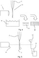
- Figs. 1-4 show different stages of a method for preparing a biological sample 3 for use in a charged particle microscope, wherein use is made of a device 1 for determining a property of the sample 3 being prepared.
- the method for preparing the biological sample 3 comprises the steps of:
- the device as disclosed herein can advantageously be used in sample preparation, and in particular in the cryo-EM sample preparation as described above.
- the device as disclosed herein can advantageously be used in each of the aforementioned sample preparation steps. It is noted that in these Figs. 1-4 the device is schematically indicated. For these reasons, several embodiments of the device will be explained first with reference to Figs. 5-7 , and after that the use of the device in Figs 1-4 will be explained in more detail.
- a first embodiment of a device 1 for determining a property of a sample 3 that is to be used in charged particle microscope is shown.
- the device shown comprises a light source 11 arranged for directing a beam of light towards said sample 3, a detector 12 arranged for detecting light emitted from said sample in response to said beam of light being incident on said sample 3; and a controller 13 connected to said detector 12 and arranged for determining a property of said matrix layer 7 based on signals received by said detector 12.
- light emitted by said light source 11 is directed towards the sample 3, and the detector 12 is arranged on the opposite side of the sample 3.
- the device 1 is arranged in such a way that the sample can be located in between the light source 11 and the detector 12.
- Light falling on the sample 3 is scattered and/or absorbed, for example, and the detector 12 detects a certain amount of light depending on the amount of scattering and/or absorption.
- the detector 12 is arranged to receive light transmitted through the sample 3. With this it is possible to determine a property of the matrix layer of the sample 3, such as, for example, the presence of the matrix layer and/or a matrix layer thickness.
- the light source 11 can be a laser, or an LED.
- the detector is arranged for detecting light emitted from the light source 11 and is thus correspondingly arranged for receiving laser light and/or LED light.
- the detector may be a CMOS sensor (in particular in combination with a laser) or a color camera (in particular in combination with an LED) as described previously.
- Other light sources are conceivable as well.
- the light source 11 is directed to the sample 3.
- the light beam can be directed to a single, relatively small spot of the sample 3.
- the light beam can be directed to a plurality of spots on the sample 3.
- the light beam can be directed to a single, relatively larger spot on the sample 3.
- the light beam is arranged for illuminating the sample 3 with a line pattern. This allows a larger part of the sample 3 to be illuminated, and simultaneously be detected by a suitable detector.
- a scanning unit (20, not shown in Fig. 5 ) is provided that is arranged for establishing a relative movement between the sample 3 and the light source 11.
- the light beam which can be a spot or a line, can be scanned over the sample 3, in order to collect spatially resolved data.
- controller 13 may be arranged for evaluating the sample 3 based on the determined property.
- the evaluation may take place based on the aforementioned spatially resolved data. Evaluation may also take place on a plurality of properties as well.
- the determined property of the matrix layer may be one or more of a measure of thickness of the matrix layer and a measure of contamination of the matrix layer.
- a measure of the thickness of the matrix layer includes the determination of the total thickness of the sample 3, including the matrix layer 7 and the sample carrier 9.
- the measure of the thickness may be qualitatively (e.g. pass or no-pass) or quantitatively (e.g. 150 nm).
- the device is arranged for determining thicknesses of the matrix layer (with or without the sample carrier 9) over a predetermined value range and with a predetermined accuracy.
- the device is arranged for detecting and determining a thickness in the range of 0 - 1000 nm, more specifically in the range of 0 - 400 nm.
- Fig. 6 shows a second embodiment of the device 1 as disclosed herein.
- the device 1 comprises a housing 10, in which a light source 11 and a detector 12 are provided.
- a semi-transparent mirror 19 is positioned in between the light source 11 and the detector 12, and aligned with optical axis O in such a way that light transmitted from the light source 11 is emitted along optical axis O, and light reflected by the sample is emitted back along optical axis O towards the detector 12.
- An optical element 15 is provided downstream of the light source 11.
- the light source is a white LED
- the optical element 15 is a lens element.
- a final lens 18 is provided.
- the optical element 15 and the final lens 18 are arranged for focusing the white LED light onto the specimen with a substantially non-parallel (but almost parallel) beam.
- the beam of light emitted from the final lens 18 is slightly converging onto the sample.
- Using a slightly unparalleled beam increases the amount of reflected light towards the device 1, and increases the signal received by the detector, in particular when the sample surface is non-perpendicular to the optical axis O.
- the optical element 15 may, for example, be a plano-convex lens with a focal length of 60 mm.
- the device 1 shown in Fig. 6 comprises a further optical element 16 that is positioned in between the detector 12 and the semi-transparent mirror 19.
- the further optical element 16 is an achromatic lens element.
- the device 1 as shown in Fig. 6 is thus arranged in such a way that an ellipsometer beam is produced.
- Ellipsometry is an optical technique for investigating the dielectric properties (complex refractive index or dielectric function) of thin films. Ellipsometry measures the change of polarization upon reflection or transmission and compares it to a model. Ellipsometry can be used to characterize composition, roughness, thickness (depth), crystalline nature, doping concentration (in semiconductor samples), electrical conductivity and other material properties. It is very sensitive to the change in the optical response of incident radiation that interacts with the material being investigated. Hence an ellipsometer beam provides advantages for use in investigating a property of a matrix layer of a specimen that is to be studied in charged particle microscopy, where samples are typically small.
- a combination of creating spatially resolved data with achromatic ellipsometry allows a special condition of the sample to be distinguished, one that was previously not possible to detect. This special condition is so-called back-side wetting of the sample. It was found that using a simple optical model based on interference, and using 3 colors, the absolute thickness of the sample (i.e. sample holder 9 and matrix layer 7) can be determined. However, it is not possible to see the exact position of the several layers contributing to the interference.
- an optical model based on interference and diffraction in which the diffracted orders are caused by the light propagation through the supporting structure having a repetitive pattern of features, like holes in a regular array, and with this it is possible to determine the absolute thickness of the total sample as well as the location of the matrix layer (i.e. front side, back-side, and/or combinations thereof). It is noted that when detecting a first or higher order diffracted beam it is advantageous to illuminate the sample under an angle such that the diffracted order propagates to the detector perpendicular from the sample plane. It is noted that for certain combinations of detected light, there are multiple solutions as to the thickness of the sample. In that case, it is possible to use the spatially resolved data to come to a conclusion of the thickness, as the thickness of the matrix layer is, in principle, continuous over at least part of the surface of the sample holder 9.
- Fig. 7 another embodiment of the device 1 is shown.
- the light source 11 is provided on one side of the sample 3, and the detector 12 is positioned on the opposite side of the sample 3.
- the sample is thus placed in between the light source 11 and the detector 12.
- the light source 11 and the detector 12 are substantially placed in line with the optical axis O.
- One or more optical elements 15, 16 such as lens elements and/or filter elements may be provided in between the light source 11 and the sample 3, and/or in between the sample 3 and the detector 12.
- the detector 12 comprises a number of different pixels 12a-12c, wherein pixels 12a are sensitive to a first band of wavelength of light, pixels 12b are sensitive to a second band of wavelength of light, and pixels 12c are sensitive to a third band of wavelength of light.
- the detector 12 comprises a multitude of different pixels 12a-12c, and for reasons of conciseness only three pixels are indicated using the reference signs 12a-12c.
- the detector 12 may be an RGB pixel camera, wherein pixels 12a are sensitive to red, pixels 12b are sensitive to green, and pixels 12c are sensitive to blue. It is conceivable that a plurality of detectors is used to obtain the same, or similar, technical effect.
- the detector 12 (or detectors) may be connected to a control unit 13, and based upon the signals received by the detector 12, the control unit is able to determine a property of the matrix layer of the sample 3.
- the light source 11 is provided with scanning means 20 in such a way that the light beam may be moved relative with respect to the sample 3. This allows a 2D matrix layer property map of the sample 3 to be generated.
- FIG. 1-4 Now turning back to Figs. 1-4 , several use cases of the device 1 will be explained. It is noted that in principle any one of the embodiments of the device as shown in Fig. 5-7 may be used. In particular the use of the embodiment shown in Fig. 6 is advantageous, as it only requires access to one side of the sample.
- the device 1 is used during a preparation step of preparing said sample.
- the device 1 is used during an application step of applying a matrix layer to said sample 3.
- a liquid matrix layer 7 containing the specimen 5 to be studied is applied to the sample holder 9.
- the sample holder 9 may be a sample grid, which are known to those skilled in the art, and may comprise a small (several millimeters) copper disc that comprises a fine mesh with a carbon foil on top.
- the liquid matrix layer 7 is applied to one side of the sample grid 9 and the device 1 may be used to check the successful application of the liquid matrix layer, i.e. by sensing an increase in thickness or a change in optical properties of the object being studied.
- the device 1 is used in a removal step of removing of an excess amount of a matrix layer 7 from said sample.
- a blotting filter 21 is used and lightly pressed against the sample 3 to allow excess fluid from the matrix layer 7 to be absorbed by the blotting paper 21. This allows a relatively small layer 7 containing the specimen 5 to be studied to be remaining on the sample holder 9.
- the device 1 may be used during the blotting step, and/or after the blotting step, to see that blotting is successfully applied. If the blotting was not successful, a further attempt may be performed. If the blotting removed too much material, it can be decided to either discard the present grid, or to reapply fresh liquid to the same grid.
- the device 1 is positioned slightly above a liquid nitrogen bath 31.
- the sample 3 may be vitrified in this bath 31, and once removed from the bath, the device 1 may be used to check the quality of the obtained sample 3. For example, ice thickness, contamination, and/or crystalline nature of the vitrified matrix layer may be investigated.
- the device is used in a similar way, with the difference that two opposing ethane jets are used in the vitrifying process. In this sense it is noted that the nature of method of vitrifying the sample is not limited to the use of the device 1 as disclosed herein.
- the device 1 may advantageously be used to investigate one or more properties of the matrix layer after a vitrification step.
- Fig. 4 it is schematically shown that the sample 3, once vitrified, may be stored.
- Options for storing include a storage box 41 or cassette, or a bath storage 42 filled with liquid nitrogen or the like.
- the device 1 may be used to check the quality of the sample 3 before or after storage. Generally, however, it is sufficient to check the quality right after vitrification, and evaluate the sample based on the results obtained.
- the device 1 may thus be advantageously used at different positions in a sample preparation tool, such as the one disclosed in WO 02/077612 A1 , which document is included herein by reference.
- the device as disclosed herein may advantageously be used in a charged particle microscope, such as an Cryo-EM.
- the device may be positioned near a sample holder and/or sample loader of the cryo-EM.
- the device as disclosed herein can check -quantitatively or qualitatively- whether the sample is suitable for use in the charged particle microscope. Additionally, it is possible to generate a 2D map of relevant parts of the sample. This allows a sample to be studied more quickly and more effectively.
Priority Applications (4)
| Application Number | Priority Date | Filing Date | Title |
|---|---|---|---|
| EP20158152.7A EP3869182A1 (de) | 2020-02-19 | 2020-02-19 | Vorrichtung und verfahren zur bestimmung einer eigenschaft einer probe, die in einem mikroskop für geladene teilchen verwendet werden soll |
| US17/168,990 US11587762B2 (en) | 2020-02-19 | 2021-02-05 | Device and method for determining a property of a sample that is to be used in a charged particle microscope |
| JP2021024034A JP2021131388A (ja) | 2020-02-19 | 2021-02-18 | 荷電粒子顕微鏡で使用されるサンプルの特性を判定するためのデバイスおよび方法 |
| CN202110187252.XA CN113281260A (zh) | 2020-02-19 | 2021-02-18 | 用于确定待在带电粒子显微镜中使用的样品的特性的装置和方法 |
Applications Claiming Priority (1)
| Application Number | Priority Date | Filing Date | Title |
|---|---|---|---|
| EP20158152.7A EP3869182A1 (de) | 2020-02-19 | 2020-02-19 | Vorrichtung und verfahren zur bestimmung einer eigenschaft einer probe, die in einem mikroskop für geladene teilchen verwendet werden soll |
Publications (1)
| Publication Number | Publication Date |
|---|---|
| EP3869182A1 true EP3869182A1 (de) | 2021-08-25 |
Family
ID=69701093
Family Applications (1)
| Application Number | Title | Priority Date | Filing Date |
|---|---|---|---|
| EP20158152.7A Pending EP3869182A1 (de) | 2020-02-19 | 2020-02-19 | Vorrichtung und verfahren zur bestimmung einer eigenschaft einer probe, die in einem mikroskop für geladene teilchen verwendet werden soll |
Country Status (4)
| Country | Link |
|---|---|
| US (1) | US11587762B2 (de) |
| EP (1) | EP3869182A1 (de) |
| JP (1) | JP2021131388A (de) |
| CN (1) | CN113281260A (de) |
Families Citing this family (1)
| Publication number | Priority date | Publication date | Assignee | Title |
|---|---|---|---|---|
| CN114216917B (zh) * | 2021-11-23 | 2024-04-12 | 长江存储科技有限责任公司 | 测试样品的表征方法 |
Citations (8)
| Publication number | Priority date | Publication date | Assignee | Title |
|---|---|---|---|---|
| WO2002077612A1 (en) | 2001-03-22 | 2002-10-03 | Universiteit Maastricht | Device for preparing specimens for a cryo-electron microscope |
| KR20070113678A (ko) * | 2006-05-25 | 2007-11-29 | 삼성전자주식회사 | 투과전자현미경용 분석시편 제조장치 및 제조방법 |
| US20100181495A1 (en) | 2009-01-22 | 2010-07-22 | Leica Mikrosysteme Gmbh | Device and method for preparing specimens |
| EP3018467A1 (de) * | 2014-11-07 | 2016-05-11 | Linkam Scienctific Instruments Ltd. | Mikroskopische probenvorbereitung |
| US20170350798A1 (en) | 2012-01-17 | 2017-12-07 | Bridget CARRAGHER | Apparatus and method for producing specimens for electron microscopy |
| WO2018073242A1 (en) * | 2016-10-17 | 2018-04-26 | Universität Basel | Lossless cryo-grid preparation by controlled sample evaporation |
| WO2019010436A1 (en) * | 2017-07-07 | 2019-01-10 | Wisconsin Alumni Research Foundation | PREPARATION OF GAS PHASE SAMPLE FOR CRYOELECTRONIC MICROSCOPY |
| EP3627138A1 (de) * | 2018-09-18 | 2020-03-25 | European Molecular Biology Laboratory | Probendickenmessanordnung und verfahren zur messung einer dicke einer probe bei kryogener temperatur durch interferometrie mithilfe eines kryostats |
Family Cites Families (3)
| Publication number | Priority date | Publication date | Assignee | Title |
|---|---|---|---|---|
| JP5307582B2 (ja) * | 2009-03-03 | 2013-10-02 | 日本電子株式会社 | 電子顕微鏡 |
| US10254107B1 (en) * | 2016-04-12 | 2019-04-09 | Falex Corporation | Ellipsometer apparatus having measurement compensation |
| US10770265B1 (en) * | 2019-03-21 | 2020-09-08 | Neptune Fluid Flow Systems LLC | System and method for preparing cryo-em grids |
-
2020
- 2020-02-19 EP EP20158152.7A patent/EP3869182A1/de active Pending
-
2021
- 2021-02-05 US US17/168,990 patent/US11587762B2/en active Active
- 2021-02-18 JP JP2021024034A patent/JP2021131388A/ja active Pending
- 2021-02-18 CN CN202110187252.XA patent/CN113281260A/zh active Pending
Patent Citations (8)
| Publication number | Priority date | Publication date | Assignee | Title |
|---|---|---|---|---|
| WO2002077612A1 (en) | 2001-03-22 | 2002-10-03 | Universiteit Maastricht | Device for preparing specimens for a cryo-electron microscope |
| KR20070113678A (ko) * | 2006-05-25 | 2007-11-29 | 삼성전자주식회사 | 투과전자현미경용 분석시편 제조장치 및 제조방법 |
| US20100181495A1 (en) | 2009-01-22 | 2010-07-22 | Leica Mikrosysteme Gmbh | Device and method for preparing specimens |
| US20170350798A1 (en) | 2012-01-17 | 2017-12-07 | Bridget CARRAGHER | Apparatus and method for producing specimens for electron microscopy |
| EP3018467A1 (de) * | 2014-11-07 | 2016-05-11 | Linkam Scienctific Instruments Ltd. | Mikroskopische probenvorbereitung |
| WO2018073242A1 (en) * | 2016-10-17 | 2018-04-26 | Universität Basel | Lossless cryo-grid preparation by controlled sample evaporation |
| WO2019010436A1 (en) * | 2017-07-07 | 2019-01-10 | Wisconsin Alumni Research Foundation | PREPARATION OF GAS PHASE SAMPLE FOR CRYOELECTRONIC MICROSCOPY |
| EP3627138A1 (de) * | 2018-09-18 | 2020-03-25 | European Molecular Biology Laboratory | Probendickenmessanordnung und verfahren zur messung einer dicke einer probe bei kryogener temperatur durch interferometrie mithilfe eines kryostats |
Also Published As
| Publication number | Publication date |
|---|---|
| US11587762B2 (en) | 2023-02-21 |
| JP2021131388A (ja) | 2021-09-09 |
| US20210257183A1 (en) | 2021-08-19 |
| CN113281260A (zh) | 2021-08-20 |
Similar Documents
| Publication | Publication Date | Title |
|---|---|---|
| KR102438824B1 (ko) | 3차원 반도체 구조체들의 검사를 위한 결함 발견 및 레시피 최적화 | |
| JP5032114B2 (ja) | パターン化ウェハまたは非パターン化ウェハおよびその他の検体の検査システム | |
| US6905838B1 (en) | Method and device for characterizing a culture liquid | |
| US7016526B2 (en) | Pixel based machine for patterned wafers | |
| JP5487196B2 (ja) | 小さな反射屈折対物レンズを用いる分割視野検査システム | |
| KR0127686B1 (ko) | 결함용 레티클 검사장치 및 방법 | |
| US20050236554A1 (en) | Optical interrogation system and method for 2-D sensor arrays | |
| CN109075091A (zh) | 用于偏光晶片检验的方法及设备 | |
| US20120092484A1 (en) | Defect inspection method and apparatus therefor | |
| EP2160591B1 (de) | Optische bildgebungsinspektionsvorrichtung mit lochkamera | |
| US20070121105A1 (en) | Optical sample characterization system | |
| KR101872240B1 (ko) | 가시광/근적외선 초분광 현미경기반 영상 측정장치를 이용한 영상 측정방법 | |
| CZ305388B6 (cs) | Analytický systém s Ramanovým mikroskopem a elektronovým mikroskopem | |
| US11587762B2 (en) | Device and method for determining a property of a sample that is to be used in a charged particle microscope | |
| CN101532944B (zh) | 光反射差法检测生物芯片装置中的小孔部件与检测方法 | |
| US8273579B2 (en) | Method and apparatus for inspecting biological samples | |
| JP2017219479A (ja) | 微小粒子計測装置及び分析方法 | |
| US11536648B2 (en) | Optical inspection device and method | |
| Quan et al. | Inspection of micro-cracks on solderball surface using a laser scattering method | |
| GB2355354A (en) | Auto-focus method | |
| EP0626575B1 (de) | Verfahren and Gerät zur mikroskopischen Abbildung | |
| Louden | Raman microscopy | |
| TWI608227B (zh) | 光學表面掃描系統及方法 | |
| US20080037009A1 (en) | Spectrometer system with IR microscope and electronically switchable detectors | |
| US20040007672A1 (en) | Method for distinguishing between biomolecule and non-biomolecule crystals |
Legal Events
| Date | Code | Title | Description |
|---|---|---|---|
| PUAI | Public reference made under article 153(3) epc to a published international application that has entered the european phase |
Free format text: ORIGINAL CODE: 0009012 |
|
| STAA | Information on the status of an ep patent application or granted ep patent |
Free format text: STATUS: THE APPLICATION HAS BEEN PUBLISHED |
|
| AK | Designated contracting states |
Kind code of ref document: A1 Designated state(s): AL AT BE BG CH CY CZ DE DK EE ES FI FR GB GR HR HU IE IS IT LI LT LU LV MC MK MT NL NO PL PT RO RS SE SI SK SM TR |
|
| STAA | Information on the status of an ep patent application or granted ep patent |
Free format text: STATUS: REQUEST FOR EXAMINATION WAS MADE |
|
| 17P | Request for examination filed |
Effective date: 20220223 |
|
| RBV | Designated contracting states (corrected) |
Designated state(s): AL AT BE BG CH CY CZ DE DK EE ES FI FR GB GR HR HU IE IS IT LI LT LU LV MC MK MT NL NO PL PT RO RS SE SI SK SM TR |
|
| STAA | Information on the status of an ep patent application or granted ep patent |
Free format text: STATUS: EXAMINATION IS IN PROGRESS |
|
| 17Q | First examination report despatched |
Effective date: 20230830 |