EP3869149B1 - Vorrichtung und verfahren zur messung von oberflächen - Google Patents
Vorrichtung und verfahren zur messung von oberflächen Download PDFInfo
- Publication number
- EP3869149B1 EP3869149B1 EP21157325.8A EP21157325A EP3869149B1 EP 3869149 B1 EP3869149 B1 EP 3869149B1 EP 21157325 A EP21157325 A EP 21157325A EP 3869149 B1 EP3869149 B1 EP 3869149B1
- Authority
- EP
- European Patent Office
- Prior art keywords
- transceivers
- edge
- sheet
- information
- distances
- Prior art date
- Legal status (The legal status is an assumption and is not a legal conclusion. Google has not performed a legal analysis and makes no representation as to the accuracy of the status listed.)
- Active
Links
Images


Classifications
-
- G—PHYSICS
- G01—MEASURING; TESTING
- G01B—MEASURING LENGTH, THICKNESS OR SIMILAR LINEAR DIMENSIONS; MEASURING ANGLES; MEASURING AREAS; MEASURING IRREGULARITIES OF SURFACES OR CONTOURS
- G01B11/00—Measuring arrangements characterised by the use of optical techniques
- G01B11/02—Measuring arrangements characterised by the use of optical techniques for measuring length, width or thickness
- G01B11/04—Measuring arrangements characterised by the use of optical techniques for measuring length, width or thickness specially adapted for measuring length or width of objects while moving
- G01B11/046—Measuring arrangements characterised by the use of optical techniques for measuring length, width or thickness specially adapted for measuring length or width of objects while moving for measuring width
-
- G—PHYSICS
- G01—MEASURING; TESTING
- G01B—MEASURING LENGTH, THICKNESS OR SIMILAR LINEAR DIMENSIONS; MEASURING ANGLES; MEASURING AREAS; MEASURING IRREGULARITIES OF SURFACES OR CONTOURS
- G01B11/00—Measuring arrangements characterised by the use of optical techniques
- G01B11/02—Measuring arrangements characterised by the use of optical techniques for measuring length, width or thickness
- G01B11/026—Measuring arrangements characterised by the use of optical techniques for measuring length, width or thickness by measuring distance between sensor and object
-
- G—PHYSICS
- G01—MEASURING; TESTING
- G01B—MEASURING LENGTH, THICKNESS OR SIMILAR LINEAR DIMENSIONS; MEASURING ANGLES; MEASURING AREAS; MEASURING IRREGULARITIES OF SURFACES OR CONTOURS
- G01B11/00—Measuring arrangements characterised by the use of optical techniques
- G01B11/02—Measuring arrangements characterised by the use of optical techniques for measuring length, width or thickness
- G01B11/06—Measuring arrangements characterised by the use of optical techniques for measuring length, width or thickness for measuring thickness ; e.g. of sheet material
-
- G—PHYSICS
- G01—MEASURING; TESTING
- G01B—MEASURING LENGTH, THICKNESS OR SIMILAR LINEAR DIMENSIONS; MEASURING ANGLES; MEASURING AREAS; MEASURING IRREGULARITIES OF SURFACES OR CONTOURS
- G01B15/00—Measuring arrangements characterised by the use of electromagnetic waves or particle radiation, e.g. by the use of microwaves, X-rays, gamma rays or electrons
- G01B15/02—Measuring arrangements characterised by the use of electromagnetic waves or particle radiation, e.g. by the use of microwaves, X-rays, gamma rays or electrons for measuring thickness
-
- G—PHYSICS
- G01—MEASURING; TESTING
- G01B—MEASURING LENGTH, THICKNESS OR SIMILAR LINEAR DIMENSIONS; MEASURING ANGLES; MEASURING AREAS; MEASURING IRREGULARITIES OF SURFACES OR CONTOURS
- G01B15/00—Measuring arrangements characterised by the use of electromagnetic waves or particle radiation, e.g. by the use of microwaves, X-rays, gamma rays or electrons
- G01B15/04—Measuring arrangements characterised by the use of electromagnetic waves or particle radiation, e.g. by the use of microwaves, X-rays, gamma rays or electrons for measuring contours or curvatures
-
- G—PHYSICS
- G01—MEASURING; TESTING
- G01B—MEASURING LENGTH, THICKNESS OR SIMILAR LINEAR DIMENSIONS; MEASURING ANGLES; MEASURING AREAS; MEASURING IRREGULARITIES OF SURFACES OR CONTOURS
- G01B15/00—Measuring arrangements characterised by the use of electromagnetic waves or particle radiation, e.g. by the use of microwaves, X-rays, gamma rays or electrons
- G01B15/08—Measuring arrangements characterised by the use of electromagnetic waves or particle radiation, e.g. by the use of microwaves, X-rays, gamma rays or electrons for measuring roughness or irregularity of surfaces
-
- G—PHYSICS
- G01—MEASURING; TESTING
- G01N—INVESTIGATING OR ANALYSING MATERIALS BY DETERMINING THEIR CHEMICAL OR PHYSICAL PROPERTIES
- G01N22/00—Investigating or analysing materials by the use of microwaves or radio waves, i.e. electromagnetic waves with a wavelength of one millimetre or more
-
- G—PHYSICS
- G01—MEASURING; TESTING
- G01N—INVESTIGATING OR ANALYSING MATERIALS BY DETERMINING THEIR CHEMICAL OR PHYSICAL PROPERTIES
- G01N33/00—Investigating or analysing materials by specific methods not covered by groups G01N1/00 - G01N31/00
- G01N33/20—Metals
-
- G—PHYSICS
- G01—MEASURING; TESTING
- G01S—RADIO DIRECTION-FINDING; RADIO NAVIGATION; DETERMINING DISTANCE OR VELOCITY BY USE OF RADIO WAVES; LOCATING OR PRESENCE-DETECTING BY USE OF THE REFLECTION OR RERADIATION OF RADIO WAVES; ANALOGOUS ARRANGEMENTS USING OTHER WAVES
- G01S13/00—Systems using the reflection or reradiation of radio waves, e.g. radar systems; Analogous systems using reflection or reradiation of waves whose nature or wavelength is irrelevant or unspecified
- G01S13/02—Systems using reflection of radio waves, e.g. primary radar systems; Analogous systems
- G01S13/06—Systems determining position data of a target
- G01S13/08—Systems for measuring distance only
-
- G—PHYSICS
- G01—MEASURING; TESTING
- G01S—RADIO DIRECTION-FINDING; RADIO NAVIGATION; DETERMINING DISTANCE OR VELOCITY BY USE OF RADIO WAVES; LOCATING OR PRESENCE-DETECTING BY USE OF THE REFLECTION OR RERADIATION OF RADIO WAVES; ANALOGOUS ARRANGEMENTS USING OTHER WAVES
- G01S13/00—Systems using the reflection or reradiation of radio waves, e.g. radar systems; Analogous systems using reflection or reradiation of waves whose nature or wavelength is irrelevant or unspecified
- G01S13/87—Combinations of radar systems, e.g. primary radar and secondary radar
- G01S13/878—Combination of several spaced transmitters or receivers of known location for determining the position of a transponder or a reflector
-
- G—PHYSICS
- G01—MEASURING; TESTING
- G01S—RADIO DIRECTION-FINDING; RADIO NAVIGATION; DETERMINING DISTANCE OR VELOCITY BY USE OF RADIO WAVES; LOCATING OR PRESENCE-DETECTING BY USE OF THE REFLECTION OR RERADIATION OF RADIO WAVES; ANALOGOUS ARRANGEMENTS USING OTHER WAVES
- G01S13/00—Systems using the reflection or reradiation of radio waves, e.g. radar systems; Analogous systems using reflection or reradiation of waves whose nature or wavelength is irrelevant or unspecified
- G01S13/88—Radar or analogous systems specially adapted for specific applications
-
- G—PHYSICS
- G01—MEASURING; TESTING
- G01S—RADIO DIRECTION-FINDING; RADIO NAVIGATION; DETERMINING DISTANCE OR VELOCITY BY USE OF RADIO WAVES; LOCATING OR PRESENCE-DETECTING BY USE OF THE REFLECTION OR RERADIATION OF RADIO WAVES; ANALOGOUS ARRANGEMENTS USING OTHER WAVES
- G01S7/00—Details of systems according to groups G01S13/00, G01S15/00, G01S17/00
- G01S7/02—Details of systems according to groups G01S13/00, G01S15/00, G01S17/00 of systems according to group G01S13/00
- G01S7/40—Means for monitoring or calibrating
- G01S7/4052—Means for monitoring or calibrating by simulation of echoes
- G01S7/4056—Means for monitoring or calibrating by simulation of echoes specially adapted to FMCW
-
- G—PHYSICS
- G01—MEASURING; TESTING
- G01B—MEASURING LENGTH, THICKNESS OR SIMILAR LINEAR DIMENSIONS; MEASURING ANGLES; MEASURING AREAS; MEASURING IRREGULARITIES OF SURFACES OR CONTOURS
- G01B2210/00—Aspects not specifically covered by any group under G01B, e.g. of wheel alignment, caliper-like sensors
- G01B2210/40—Caliper-like sensors
- G01B2210/44—Caliper-like sensors with detectors on both sides of the object to be measured
-
- G—PHYSICS
- G01—MEASURING; TESTING
- G01S—RADIO DIRECTION-FINDING; RADIO NAVIGATION; DETERMINING DISTANCE OR VELOCITY BY USE OF RADIO WAVES; LOCATING OR PRESENCE-DETECTING BY USE OF THE REFLECTION OR RERADIATION OF RADIO WAVES; ANALOGOUS ARRANGEMENTS USING OTHER WAVES
- G01S13/00—Systems using the reflection or reradiation of radio waves, e.g. radar systems; Analogous systems using reflection or reradiation of waves whose nature or wavelength is irrelevant or unspecified
- G01S13/74—Systems using reradiation of radio waves, e.g. secondary radar systems; Analogous systems
- G01S13/75—Systems using reradiation of radio waves, e.g. secondary radar systems; Analogous systems using transponders powered from received waves, e.g. using passive transponders, or using passive reflectors
-
- G—PHYSICS
- G01—MEASURING; TESTING
- G01S—RADIO DIRECTION-FINDING; RADIO NAVIGATION; DETERMINING DISTANCE OR VELOCITY BY USE OF RADIO WAVES; LOCATING OR PRESENCE-DETECTING BY USE OF THE REFLECTION OR RERADIATION OF RADIO WAVES; ANALOGOUS ARRANGEMENTS USING OTHER WAVES
- G01S7/00—Details of systems according to groups G01S13/00, G01S15/00, G01S17/00
- G01S7/02—Details of systems according to groups G01S13/00, G01S15/00, G01S17/00 of systems according to group G01S13/00
- G01S7/024—Details of systems according to groups G01S13/00, G01S15/00, G01S17/00 of systems according to group G01S13/00 using polarisation effects
- G01S7/025—Details of systems according to groups G01S13/00, G01S15/00, G01S17/00 of systems according to group G01S13/00 using polarisation effects involving the transmission of linearly polarised waves
Definitions
- the invention relates to an apparatus for and a method of measuring a surface.
- An imaging system that typically has a camera may capture images of the moving metal sheet, and an image processing computer program may be used to determine a value for any measured feature detectable in the images.
- dust and steam such as an emulsion steam deteriorate the visibility of the moving metal sheet and the heat may cause heat distortion to image. The heat may also cause a high requirement to the optics.
- an imaging system is structurally and operationally complicated.
- Ultrasound measurement systems suffer from a low accuracy, and the ultrasound waves are detracted with the moving air, which causes errors in the measurement results.
- Radioactivity such as thickness of the metal sheet have been measured using radioactivity, X-rays, lasers, eddy-currents, test contact probes, and microwave resonators.
- a use of a radioactivity source requires a permission, and a massive protection against the radiation which results in a challenging technical and economic situation in order to be a realistic measurement. It also requires a separate calibration for each metal, and the measurement is slow.
- the radioactivity measurements are receding technologies.
- the X-ray measurements are rather similar to the measurements based on radioactivity except that the X-ray radiation can be switched off when a measurement is not performed. Additionally, the X-ray tubes need to be renewed.
- the probes that are in a physical contact with the metal sheet are not perfectly non-invasive and may scratch the surface. Additionally, the measurement with a physical contact is slow.
- the measurements based on the lasers expressly require that the specular reflection is directed to the detector, which is not fulfilled when a direction of the bright metal surface i.e. a direction of a normal of the metal surface varies.
- a direction of the bright metal surface i.e. a direction of a normal of the metal surface varies.
- dust and vapours cause problems to optical radiation of the lasers.
- the measurement with eddy-currents does not work with ferrous metals. Additionally, the measurement range and gap are narrow.
- the measurements based on microwaves are sensitive to a variation of a tilting of the metal surface i.e. to a tilt of a normal of the metal surface. This leads to similar technical problems as the measurement with a laser.
- Patent document EP2594 658 presents a baffle plate unit and a gas wiping device using the baffle plate unit.
- Patent document DE202016008273 presents a device for determining the positions of the edges and the width of a metal strip.
- Patent document WO2018175995 presents an apparatus and a method for a thickness and velocity measurement of flat moving materials using high frequency radar technologies.
- Patent document DE102017010124 present an arrangement for determining the width of a plate with a measuring device with a first sensor device.
- Figures illustrate various embodiments, they are simplified diagrams that only show some structures and/or functional entities.
- the connections shown in the Figures may refer to logical or physical connections. It is apparent to a person skilled in the art that the described apparatus may also comprise other functions and structures than those described in Figures and text. It should be appreciated that details of some functions, structures, and the signalling used for measurement and/or controlling are irrelevant to the actual invention. Therefore, they need not be discussed in more detail here.
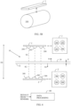
- Figure 1A and 1B illustrate an example of an apparatus for measuring a surface of a sheet 10.
- Sensor arrangements 2 in Figures 1A, 1B , 3A , 3B and 5 are shown from two orthogonal viewing angles, side and top.
- a curved arrow illustrates a turn from top to side.
- the sensor arrangements shown side and top do not show the same arrangement 2, 2' but two different but possible arrangements.
- the sheet 10 may be electrically conductive and moving.
- the sheet 10 may be a metal sheet.
- the sheet 10 may have an electrically conductive surface but material below or within the electrically conductive surface may be an electrical insulator.
- the sheet 10 may be an insulator without an electrically conductive surface.
- the sheet 10 is not moving but is immobile while the measurement is performed.
- the claims define a moving, not immobile, surface.
- many of the measurements are described to be performed to the sheet 10, particularly a measurement of thickness, a measured object does not necessarily need to be a sheet but it may be an object of any shape (see an example relating to a roll in Figure 5B ).
- the claims are directed to a moving surface in the context of a sheet and not to any object as such.
- At least two first sensors 100, 102, 104 are distributed parallel with a longitudinal extent of a first edge 12 of the sheet 10.
- the two sensors in Figure 1A are 100 and 102, for example, the two sensors being useful to understand the invention. It can be considered that the at least two sensors 100, 102 have a distance therebetween, the distance being in a single dimension such that the two first sensors 100, 102 are distributed one-dimensionally in space.
- the single dimension is at least approximately parallel to the longitudinal extent i.e. length of the first edge 12.
- the single dimension can be considered and it typically is horizontal.
- the at least two first sensors 100, 102, 104 have an interaction with the surface of the edge 12 of the sheet 10 in a contactless manner using a microwave range of electromagnetic signals.
- Wavelengths of the microwave signals may be in a millimeter range.
- a frequency range of the microwave signals may start from a minimum frequency about 10GHz.
- a frequency range of the microwave signals may start from a minimum frequency about 30GHz.
- a frequency range of the microwave signals may start from a minimum frequency about 100GHz.
- a frequency range of the microwave signals may start from a minimum frequency about 300GHz.
- a frequency range of the microwave signals may start from a minimum frequency about 100GHz.
- a frequency range of the microwave signals may go upto about 300GHz.
- a frequency range of the microwave signals may go upto about 450GHz.
- At least one of the at least two first sensors 100, 102, 104 receives and/or detects at least two of the signals of the interaction as a reflection from the first edge 12.
- the reflected signals also carry information relating to distances between the at least two first sensors 100, 102, 104 and the first edge 12 at different longitudinal sections 14, 16 of the sheet 10.
- the microwave signals reflect from the first edge 12 in a direction parallel to a normal of the first edge 12 of the sheet 10.
- the rectangle angle of the normal opens on a plane a normal of which is parallel to a normal of a first main surface 30 (see rectangle angle 90° in Figure 1B ).
- a data processing unit 180 receives the information relating to distances between the at least two first sensors 100, 102, 104 and the first edge 12 at different longitudinal sections 14, 16 of the sheet 10.
- the data processing unit 180 also determines at least one geometrical parameter of the first edge 12.
- the at least one geometrical parameter may include information on a geometry of the first edge 12.
- the at least one geometrical parameter may include a location of the first edge 12 of the moving sheet 10 based on the information on the distances. The location may be determined in a horizontal direction, in a vertical direction or in a vertical and horizontal directions.
- the location may mean a location of the first edge 12 with respect to the at least two first sensors 100, 102, 104. However, as it is possible that the position of the at least two first sensors 100, 102, 104 is known with respect to an external coordinate system.
- the data processing unit 180 may then determine the location of the first edge 12 according to the external coordinate system.
- the external coordinate system may refer to measures of a system that is used to manufacture of the sheet 12, for example.
- the external coordinate system may refer to global coordinates, for example.
- a desired direction DD may be parallel to a longitudinal axis of the sheet 10 or a direction of movement M of the sheet 10.
- the desired direction DD is the same as the single dimension that is at least approximately horizontal.
- the at least one geometrical parameter may include information on a direction of the first edge 12 of the sheet 10 with respect to the desired direction DD.
- the at least one geometrical parameter may include information on a variation of a direction of the first edge 12, which may refer to or be based on a variation of the distance between the first edge 12 and the at least two sensors 100 to 104.
- the at least one geometrical parameter may include information on waviness or curviness of the first edge 12.
- the waviness or curviness may mean a random or determined variation with respect to a straight line.
- the straight line in turn, may refer to an averaged and constant position of the first edge 12 or a predetermined straight line.
- the direction of the first edge 12 may be computed on the basis of the distances the microwaves travel between a transmitter and a receiver.
- sensors 100 and 102 are transceivers i.e. the same sensor transmits and receives the microwaves.
- the microwave from the sensor 100 travels 2L between transmission and reception as can be seen in Figure 1B .
- the microwaves from the sensor 102 travels 2L' between transmission and reception.
- 2L is longer than 2L', and a difference between 2L and 2L' depends deterministically on an angle ⁇ which is a deviation of the first edge 12 from the desired direction.
- the direction of the first edge 12 may be computed on the basis of the distances L and L' in the data processing unit 180.
- a corresponding result can easily be achieved in the case the sensors 100, 102 are not transceivers. In general, the sensors 100, 102 do not need to be transceivers in order to compute the direction of the first edge 12.
- the apparatus may comprise at least three first sensors 100 to 104; 200 to 206, which are distributed two-dimensionally in space (see Figures 1A to 8 ).
- the at least three first sensors 200 to 206 may be called at least three first main surface sensors 200 to 206 when they measure a first main surface 30 or a second main surface 32.
- the at least three first sensors 100 to 104 may be considered to measure and a first edge 12.
- the at least three first sensors 100 to 104; 200 to 206 may have a component also in a third dimension.
- the microwave sensors 100 to 104 refer to the sensor that are explained earlier in conjunction with Figures 1A, 1B . In an embodiment, there may be four or more of the at least three first sensors.
- Said at least three first sensors 100 to 104; 200 to 206 interact with the surface of the sheet 10 in a contactless manner using a microwave range of electromagnetic signals. At least two of the at least three first sensors 100 to 104; 200 to 206 receive at least two of the microwave signals of the interaction. The at least two of the microwave signals of the interaction are reflected from the surface of the sheet 10. The two of the microwave signals carry information relating to distances between the at least three first sensors 100 to 104; 200 to 206 and the surface of the sheet 10. The microwave signals reflect in a direction parallel to a normal of the surface of the sheet 10 at the first edge 12 (and at second edge 22). The beam widths of the sensors are wide enough for transmission and reception such that the reflection can be measure even when the surface is tilted.
- the transmitting and receiving sensors of the at least three first sensors 100 to 104; 200 to 206 are selected two-dimensionally such that microwave signals of the interaction represent both dimensions of the space of two-dimensional distribution of the at least three first sensors 100 to 104; 200 to 206.
- the data processing unit 180 then receives said information on the distances, and determines at least one geometrical parameter of the sheet 10.
- the at least one geometrical parameter may be a geometrical feature of the sheet 10 or a location of the sheet 10 for example.
- the at least two or three sensors 100 to 104 which are used to measure the first edge 12, may use linear polarization a direction of which is parallel to a longitudinal axis of the sheet 10. The polarization allows a strong reflection from the first edge 12.
- the at least two or three sensors 100 to 104 which are used to measure the first edge 12, may use linear polarization a direction of which is at about 45° angle with respect to the longitudinal axis of the sheet 10.
- a field of the microwave transmission induce an electric current in a direction of the longitudinal axis of the sheet 10 at the first edge 12.
- the electric current then radiates linearly polarized microwaves a direction of which is orthogonal to that of the transmitted microwaves. Interfering reflections from other electrically conducting surfaces may be attenuated or eliminated when either of the polarizations is utilized.
- a width of the sheet 10 may be measured using only the at least two or three sensors 100 to 104 at one side of the sheet 10.
- the microwaves reflect then from both the first edge 12 and the second edge 22 as surface waves.
- a temporal difference between receptions of the microwaves then is comparable to the width of the sheet 10.
- a property that depends on the temporal difference may be detected using a direct time measurement, a phase measurement of the microwave signals or the like that is known, per se, in the prior art.
- the transmitted microwaves may be circularly polarized.
- the reception may then be performed in a linearly polarized manner or in a circularly polarized manner.
- the at least three first sensors 100 to 104; 200 to 206 may comprise at least two first sensors 100 to 104, which are distributed parallel with a longitudinal extent of a first edge 12 of the sheet 10 for making it possible for the data processing unit 180 to determine the at least one geometrical parameter of the first edge 12 as already explained.
- the data processing unit 180 may determine an angle of the first edge 12 with respect to a direction of the desired direction of the sheet 10 as the at least one geometrical parameter of the sheet 10 based on the information relating to the difference of the distances between the at least three first sensors 100 to 104; 200 to 206 and the surface of the sheet 10.
- the desired direction of the sheet 10 may be a predetermined direction at which the sheet 10 is moving or should move during its processing such as manufacturing or later treatment, for example.
- the apparatus may comprise at least two second sensors 150, 152, 154, which are distributed parallel to a longitudinal extent of a second edge 22 of the sheet 10.
- the at least two second sensors 150, 152, 154 are located opposite to the first edge 12 and on an opposite side of the sheet 10 with respect to the at least first two or three sensors 100 to 106.
- the at least two second sensors 150 to 154 may have the interaction with the surface of the second edge 22 in the contactless manner using the microwave range of the electromagnetic signals.
- Sensor arrangements 3 in Figures 2, 3A are shown from two orthogonal viewing angles, side and top. A curved arrow illustrates a turn from top to side.
- the at least two second sensors 150 to 154 may receive at least two of the microwave signals of the interaction, the microwave signals carrying information relating to distances between the at least two second sensors 150 to 154 and the second edge 22 at different sections 24, 26 of the sheet 10 spaced in a longitudinal direction of the sheet 10 from each other.
- the data processing unit 180 may receive the information on the distances, and determine at least one geometrical parameter of the second edge 22 based on the information.
- the at least one geometrical parameter may include information on a geometry of the second edge 22.
- the at least one geometrical parameter may include a location of the second edge 22 of the moving sheet 10 based on the information on the distances.
- the at least one geometrical parameter may include information on a direction of the second edge 22 of the sheet 10 with respect to the desired direction DD.
- the at least one geometrical parameter may include information on a variation of a direction of the second edge 22, which may refer to or be based on a variation of the distance between the second edge 22 and the at least two sensors 150 to 154.
- the at least one geometrical parameter may include information on waviness of the second edge 22.
- the apparatus may comprise a first additional transceiver sensor 108 that may transmit a microwave signal over the sheet 10.
- the transceiver sensor 108 may comprise an integrated transceiver or a combination of a separate transmitter and receiver.
- the microwave signal may travel over the first main surface 30 or the second main surface 32.
- the microwave signal may be directed to a first reflecting reference 110 that has a known location with respect to the at least two second sensors 150 to 154 or the second edge 22.
- the microwave signal may travel in a direction that has a component parallel to a normal of the first and second edges 12, 22.
- the first additional transceiver sensor 108 may receive a reflection of the microwave signal from the first reflecting reference 110.
- the reflection from the first reflecting reference 110 carries a transverse information relating to a distance between the first additional transceiver sensor 108 and the first reflecting reference 110.
- the data processing unit 180 may receive the transverse information, and determine a width of the sheet 10 based on the transverse information, the location of the first edge 12 and the location of the second edge 22.
- dust and steam that may disturb the microwave measurement can be compensated in the measurement because of the reflection from the first reflecting reference 110 or the detection with a receiver microwave sensor used instead of the first reflecting reference 110 (explained later).
- the at least two or three sensors 150 to 154 which are used to measure the second edge 22, may use linear polarization a direction of which is parallel to a longitudinal axis of the sheet 10.
- the polarization allows a strong reflection from the second edge 22. This is an advantage when a thin sheet 10 is measured.
- a sheet 10 is thin when its thickness is smaller than a wavelength of the microwave transmission.
- the at least two or three sensors 150 to 154, which are used to measure the second edge 22 may use linear polarization a direction of which is at about 45° angle with respect to the longitudinal axis of the sheet 10.
- a field of the microwave transmission induce an electric current in a direction of the longitudinal axis of the sheet 10 at the second edge 22. The electric current then radiates linearly polarized microwaves the polarization of which is orthogonal to that of the transmitted microwaves.
- the apparatus may comprise a receiving reference sensor 110' instead of the first reflecting reference 110. Then the received microwave signal received by the receiving reference sensor 110' carries a transverse information relating to a distance between the first additional transmitter sensor 108' and the receiving reference sensor 110', this transverse information being similarly usable as that carried by the reflection from the first reflecting reference 110.
- the at least two or three first sensors 100 to 106 may transmit microwaves in a direction that has a component parallel to a normal of the first edge 12 to a second reflecting reference 160 that is located over the sheet 10.
- the word “over” means that the second reflecting reference 160 has a distance from the first main surface 30 or the second main surface 32 in a direction of a normal of the first main surface 30 or the second main surface 32.
- the word “over” should also be understood to cover the situation where of the second reflecting reference 160 is located under the sheet 10.
- Said at least two or three first sensors 100 to 106 may also receive a reflection of the microwaves from the second reflecting reference 160.
- the reflection carries a first reference information relating to a distance between said one of the at least two or three first sensors 100 to 106 and the second reflecting reference 160.
- the second reflecting reference 160 is in a known position, which may be a constant position. In that way the first edge 12 of the sheet 10 may be determined accurately.
- said at least two or three second sensors 150, 152, 154 may transmit a microwave signal in a direction that has a component parallel to a normal of the second edge 22 to a third reflecting reference 162.
- Said at least two second sensors 150, 152, 154 may receive a reflection of the microwave signal from the third reflecting reference 162.
- the reflection carries a second reference information relating to a distance between said at least two second sensors 150, 152, 154 and the third reflecting reference 162.
- the data processing unit 180 may receive the first reference information and the second reference information, and determine a width W of the sheet 10 based on the first transverse information, the second reference information, distance between the second reflecting reference 160 and the third reflecting reference 162, the location of the first edge 12 and the location of the second edge 22.
- the third reflecting reference 162 is in a known position, which may be a constant position. In that way the second edge 22 of the sheet 10 may be determined accurately. In an embodiment, the stability of the position of the second and third reflecting references 160, 162 may be ensured and/or corrected by measuring their temperature in order to compensate an effect of the thermal expansion.
- the second reflecting reference 160 and the third reflecting reference 162 may be separated from each other by a distance T in a direction at least approximately parallel to a normal of the first edge 12 and/or the second edge 22.
- the second reflecting reference 160 and the third reflecting reference 162 may be connected to each other by a solid material.
- the solid material which may be a bar or the like, may be made of thermally stable material.
- the thermally stable material may comprise invar, for example. The thermally stable material allows a thermally immobile location for the second reflecting reference 160 and the third reflecting reference 162.
- the angle ⁇ which is a deviation between the microwave signals with respect to first edge 12 and the second reflecting reference 160, may be taken into account in the measurement of the width W of the sheet 10.
- the angle ⁇ which is a deviation between the microwave signals with respect to second edge 12 and the third reflecting reference 162, may also be taken into account in the measurement of the width W of the sheet 10.
- the data processing unit 180 may perform an algorithm that corresponds to the mathematical expression.
- the apparatus comprises the at least three first sensors 100 to 104.
- the at least three first sensors 100, 102, 104 may receive at least two of the microwave signals of the interaction with information relating to distances between the at least three first sensors 100, 102, 104 and the first edge 12 of the sheet 10 as a reflection in a direction parallel to a normal of the first edge 12, the microwave signals of the interaction representing both dimensions of the space of two-dimensional distribution of the at least three first sensors 100, 102, 104.
- the data processing unit 180 may receive said information on the distances, and determine a shift of the sheet 10 in a vertical direction as a geometrical parameter on the basis of the information on the distances.
- the data processing unit 180 may receive said information on the distances, and determine a shift of the sheet 10 in a transverse direction to both a normal of the first edge 12 and the direction of a longitudinal axis of the sheet 10 as a geometrical parameter on the basis of the information on the distances.
- the sheet 10 is on rolls or a conveyer belt, and thus it can shift only upward from the rolls or the conveyer belt.
- the vertical shift may be detected and indicated based on the following geometrical features.
- the sheet 10 is a position A which is for simplicity in the middle of the sensors 100, 104, for example. Then the distance between the sensor 100 and the first edge 12 of the sheet 10 is x. The distance between the sensor 104 and the first edge 12 of the sheet 10 is also x. Then distance the microwaves travel from the sensor 100 via the first edge 12 to the sensor 104 is 2x.
- the sheet 10 is a position B, which deviates from the position A. Then the distance between the sensor 100 and the first edge 12 of the sheet 10 is x'. The distance between the sensor 104 and the first edge 12 of the sheet 10 is x".
- the microwaves travel from the sensor 100 via the first edge 12 to the sensor 104 is x' + x", which is longer than 2x.
- the difference between the distances 2x and x' + x" depends deterministically from the vertical shift S, which can easily be shown with elementary geometry.
- the at least three first sensors 200 to 206 may receive, due to reflection, at least two of the microwave signals of the interaction with the first main surface 30 of the sheet 10.
- the interaction may take place with the second main surface 32 of the sheet 10 (see Figure 6 ; this embodiment is also not claimed as such).
- the microwave signals may carry information relating to distances between the at least three first sensors 200 to 206 and the first main surface 30 of the sheet 10.
- the reflection of the microwave signals may have a component in a direction parallel to a normal of the first main surface 30.
- the microwave signals of the interaction represent both dimensions of the space of two-dimensional distribution of the at least three first sensors 200 to 206.
- the data processing unit 180 may receive said information on the distances, and compare the first main surface 30 to a desired reference based on the distances between the at least three first sensors 200 to 206 and the first main surface 30 included in the information. Then the data processing unit 180 may determine a deviation of the first main surface 30 from a desired reference based on differences of the distances between the at least three first sensors 200 to 206 and the first main surface 30 included in the information. The deviation may be considered the at least one geometrical parameter.
- the at least three sensors 200 to 206 may be correspondingly over the second main surface 32 and the data processing unit 180 may determine a deviation of the second main surface 32 in a similar manner.
- the desired reference may be a flat surface, for example.
- the desired reference may be a deterministically curved surface, for example. Namely, the sheet 10 may be curved.
- the roll 350 may be a part of a manufacturing machine of a steel factory or a paper mill, for example.
- the at least one geometrical parameter may, in the examples of Figures 5 and 6 , represent a tilt angle of the first main surface 10 in one direction or in two orthogonal directions.
- an apparatus for measuring a surface comprises first sensors 100 to 104; 200 to 206, which are distributed two-dimensionally in space, except in the measurement of either of the edges 12, 22 it is possible to have a distribution of the sensors in one dimension or two dimensions.
- Said first sensors 100, 102, 104; 200 to 206 interact with the surface in a contactless manner using a microwave range of electromagnetic signals.
- the first sensors 100 to 104; 200 to 206 receive at least two of the microwave signals of the interaction with information relating to distances between the sensors 100 to 104; 200 to 206 and the surface as a reflection.
- the microwave signals of the interaction represent both dimensions of the space of two-dimensional distribution of the first sensors 100 to 104; 200 to 206, except in the measurement of either of the edges 12 and 22 the interaction may cover one dimension or two dimensions although otherwise the measurement of the edge 12, 22 is similar.
- a data processing unit 180 receives said information on the distances, and determines at least one geometrical parameter of the surface on the basis of the information.
- the at least three first sensors 200 to 206 may comprise at least four sensors, which may receive at least three of the microwave signals of the interaction as a reflection, the microwave signals carrying information relating to the distances between the at least four first sensors and a first main surface 30.
- the microwave signals of the interaction representing both dimensions of the space of two-dimensional distribution of the at least four first sensors.
- the data processing unit 180 may receive said information on the distances, and determine a waviness of the first main surface 30 based on differences of the distances between the at least four first sensors and the first main surface 30 included in the information.
- the at least three sensors 200 to 206 may be correspondingly over the second main surface 32 and the data processing unit 180 may determine a deviation of the second main surface 32 in a similar manner.
- the apparatus may comprise at least three second sensors 300, 302, 304, 306 at a known distance D2 from the at least three first sensors 200 to 206.
- the at least three second sensors 300 to 306 are distributed two-dimensionally in space (may have a component also in third dimension).
- Said at least three first sensors 300 to 306 may have an interaction with a second main surface 32 of the sheet 10 opposite to the first main surface 30 in a contactless manner using a microwave range of electromagnetic signals.
- At least two of the at least three second sensors 300 to 306 may receive at least two of the microwave signals of the interaction.
- the microwave signals may carry information relating to distances between the at least three second sensors 300 to 306 and the second main surface 32.
- the microwave signals of the interaction represent both dimensions of the space of two-dimensional distribution of the at least three second sensors 300 to 306.
- the data processing unit 180 may receive said information on the distances, and determine a thickness P of the sheet 10 based on the distance between the at least three first sensors 200 to 206 and the first main surface 30, the distance between the at least three second sensors 300 to 306 and the second main surface 32 included in the information from both sides of the sheet 10, and the known distance between the at least three first sensors 200 to 206 and the at least three second sensors 300 to 306.
- the thickness of the sheet 10 can be determined more accurately than otherwise.
- That the measurement is performed at the same positions means that each pair of the measurements of opposite sides of the sheet 10 is performed at the same position on a plain determined by a normal N1, N2 of the first main surface 30 and/or the second main surface 32 (see Figures 5A , 6 ).
- a distance between the sensor arrangement 2 and the sheet 10/the first surface 30 is K1.
- a distance between the sensor arrangement 2' and the sheet 10/the second surface 32 is K2.
- the black dots represent separate examples of a single location where distance measurements may be projected on such that a distance between the sensor arrangement 2, 2' and the sheet 10 is determined from a single point.
- only one transceiver sensor 200 over the first main surface 30 and only one transceiver sensor 300 over the second main surface 32 may be used to measure the thickness of the sheet 10.
- only two transceiver sensors 200, 202 over the first main surface 30 and only two transceiver sensors 300, 302 over the second main surface 32 may be used to measure the thickness of the sheet 10.
- Figure 7 illustrates an example, which is not claimed as such, where the at least three sensors 100 to 104 comprise one transmitter TX1 and two receivers RX1 and RX2 for measuring the edge 12 of the sheet.
- the at least three sensors 100 to 104 may comprise two transmitters and one receiver in order to have the same measurement configuration and geometry which allows the data processing unit 180 to determine the at least one geometrical parameter.
- FIG 8 illustrates an example of an embodiment, where a transceiver 800 may transmit the microwaves towards the first edge 12 of the sheet 10.
- the microwaves reflect back to the transceiver 800 from the first edge (see microwaves 400).
- the distance between the transceiver 800 and the first edge 12 may be measured by the data processing unit 180 on the basis of effects caused by the distance to the microwaves. In this case, the microwaves travel a distance LR, which is measured as explained in conjunction with Figure 1 .
- the transceiver 800 may comprise an integrated transmitter and receiver. Alternatively, the transceiver 800 may comprise a transmitter and a receiver that are separate.
- the transceiver 800 can be understood to be included in the at least two sensors 100, 102, 104.
- the transceiver 800 may transmit the microwaves towards a fourth reflecting reference 802 on the opposite side of the sheet 10 with respect to the transceiver 800.
- the microwaves reflect back to the transceiver 800 from the fourth reflecting reference 802 (see microwaves 402).
- the distance between transceiver 800 and the the fourth reflecting reference 802 may be measured by the data processing unit 180 on the basis of effects caused by the distance to the microwaves.
- the distance LT and the width W remain unknown.
- the width W may be determined in the following manner.
- the transceiver 800 may transmit the microwaves towards the fourth reflecting reference 802. In this case the microwaves reflect from the fourth reflecting reference 802 to the second edge 22 wherefrom the microwaves reflect back to the fourth reflecting reference 802. Then the microwaves reflect from the fourth reflecting reference 802 back to the transceiver 800 (see microwaves 404).
- the distance between the transceiver 800 and the the fourth reflecting reference 802 may be measured by the data processing unit 180 on the basis of effects caused by the distance to the microwaves.
- width W E/2 - (LR + LT)
- W 2 * E ⁇ LR ⁇ F / 2 .
- the fourth reflecting reference 802 may be a separate reflector or it may the same as or a part of the first reflecting reference 110.
- Any of the reflecting references 110, 160, 162, 802 may comprise a retroreflector such as a triangular corner reflector (similar to those used in radar technology), a flat metal surface and/or a spherical surface (if a radius of the spherical surface is at least approximately the same as a distance to a transmitter, the spherical surface will reflect the transmission back to the transmitter).
- the sensors 100 to 106, 200 to 206, 300 to 306 may comprise lens antennas, which provide narrow beams.
- the opening angle of the beam of the microwave transmission and/or reception may be about 10°, for example.
- the opening angle of the beam of the microwave transmission and/or reception may be about 5°, for example.
- the operation frequency of the sensors 100 to 106, 200 to 206, 300 to 306 may be in a frequency band about 20 GHz to 300 GHz, for example.
- the determination of the at least one geometrical parameter may be based on a frequency modulated continuous wave (FMCW) method. Additionally or alternatively, the determination of the at least one geometrical parameter may be based on a method of flight times of one or more microwave pulses, noise correlation method or the like for example.
- FMCW frequency modulated continuous wave
- the FMCW method may allow a high accuracy in the determination of the at least one geometrical parameter on the basis of phase measurements.
- effects of the vapour around the sheet 10 may be decreased by a blower 190 such as a fan which blows the steam away from the space where the microwaves travel (see Figure 2 ).
- a blower 190 such as a fan which blows the steam away from the space where the microwaves travel (see Figure 2 ).
- the data processing unit 180 comprises one or more processors 1000, and one or more memories 1002 including a computer program code. Then the one or more memories 1002, the one or more processors 1000 and a computer program code may cause the data processing unit 180 to process the information from the sensors. The data processing unit 180 may also control the measurement.
- FIG 11 is a flow chart of a measurement method of a surface of the sheet 10 at the first edge 12.
- electromagnetic signals of a microwave range are transmitted 1100, with at least two first sensors 100, 102, 104, to the surface of a sheet 10 at a first edge 12 for causing an interaction with the surface of the sheet 10 in a contactless manner, the at least two first sensors 100, 102, 104 being distributed parallel with a longitudinal extent of first edge 12 of the sheet 10.
- step 1102 at least two of the microwave signals of the interaction with information relating to distances between the at least two first sensors 100, 102, 104 and the first edge 12 as a reflection at different longitudinal sections 14, 16 of the sheet 10 are received by at least one of the at least two first sensors 100, 120, 104.
- the information is received by a data processing unit 180, and at least one geometrical parameter of the first edge 12 of the moving sheet 10 is determined based on the information by the data processing unit 180.
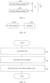
- Figure 12 is a flow chart of the measurement method of a surface.
- electromagnetic signals of a microwave range are transmitted 1200, with at least three first sensors 100, 102, 104;200, 202, 204, to the surface for causing an interaction with the surface in a contactless manner, at least three first sensors 100 to 104; 200 to 206 being distributed two-dimensionally in space.
- step 1202 at least two of the microwave signals of the interaction with information relating to distances between the at least three first sensors 100 to 104; 200 to 206 and the surface as a reflection are received by at least two of the at least three first sensors 100, 120, 104; 200, 202, 204, the microwave signals of the interaction representing both dimensions of the space of two-dimensional distribution of the at least three first sensors 100 to 104; 200 to 206.
- said information is received 1204 by a data processing unit 180, and at least one geometrical parameter of the surface is determined on the basis of the information by the data processing unit 180.
- the method steps 1104 and 1104 of Figures 11 and 12 may be implemented as a logic circuit solution or computer program.
- the computer program may be placed on a computer program distribution means for the distribution thereof.
- the computer program distribution means is readable by a data processing device, and it encodes the computer program commands, carries out computations required for determining the at least one geometrical parameter, and optionally controls the measurements.
- the computer program may be distributed using a distribution medium which may be any medium readable by the controller.
- the medium may be a program storage medium, a memory, a software distribution package, or a compressed software package.
- the distribution may be performed using at least one of the following: a near field communication signal, a short distance signal, and a telecommunications signal.
Landscapes
- Physics & Mathematics (AREA)
- Engineering & Computer Science (AREA)
- General Physics & Mathematics (AREA)
- Radar, Positioning & Navigation (AREA)
- Remote Sensing (AREA)
- Electromagnetism (AREA)
- Computer Networks & Wireless Communication (AREA)
- Life Sciences & Earth Sciences (AREA)
- Health & Medical Sciences (AREA)
- Chemical & Material Sciences (AREA)
- Analytical Chemistry (AREA)
- Biochemistry (AREA)
- General Health & Medical Sciences (AREA)
- Immunology (AREA)
- Pathology (AREA)
- Food Science & Technology (AREA)
- Medicinal Chemistry (AREA)
- Length-Measuring Devices Using Wave Or Particle Radiation (AREA)
Claims (11)
- Vorrichtung zum Messen einer sich bewegenden Fläche, dadurch gekennzeichnet, dass die Vorrichtung Folgendes umfasstmindestens drei erste Sendeempfänger (100 bis 104; 200 bis 206), die im Raum zweidimensional verteilt sind, wobei die mindestens drei ersten Sendeempfänger (100 bis 104; 200 bis 206) dazu ausgelegt sind, mit der Fläche in einer kontaktlosen Weise unter Verwendung eines Mikrowellenbereichs von elektromagnetischen Signalen zu interagieren, und dazu ausgelegt, Mikrowellensignale der Interaktion mit Informationen zu empfangen, die sich auf Abstände zwischen den mindestens drei Wandlern (100 bis 104; 200 bis 206) und der Fläche als eine Reflexion beziehen;die mindestens drei ersten Sendeempfänger (100 bis 104; 200 bis 206) umfassen mindestens zwei erste Sendeempfänger (100 bis 104), die parallel zu einer Längserstreckung einer Fläche einer ersten Kante (12) einer Platte (10) parallel verteilt sind;die mindestens zwei ersten Sendeempfänger (100 bis 104) sind dazu ausgelegt, die Interaktion mit der Fläche der ersten Kante (12) in der kontaktlosen Weise unter Verwendung des Mikrowellenbereichs der elektromagnetischen Signale zu haben;die mindestens zwei ersten Sendeempfänger (100 bis 104) sind dazu ausgelegt, mindestens zwei der Mikrowellensignale der Interaktion mit Informationen zu empfangen, die sich auf Abstände zwischen den mindestens zwei ersten Sendeempfängern (100 bis 104) und der ersten Kante (12) in verschiedenen Längenabschnitten (14, 16) der Platte (10) beziehen, wobei die Mikrowellensignale der Interaktion beide Dimensionen des Raums der zweidimensionalen Verteilung der mindestens drei ersten Sendeempfänger (100 bis 104; 200 bis 206) repräsentieren; undeine Datenverarbeitungseinheit (180), die dazu ausgelegt ist, die Informationen zu empfangen und mindestens einen geometrischen Parameter der ersten Kante (12) auf Basis der Informationen zu bestimmen.
- Vorrichtung nach Anspruch 1, dadurch gekennzeichnet, dass die Datenverarbeitungseinheit (180) dazu ausgelegt ist, einen Winkel (α) der ersten Kante (12) mit Bezug auf eine Richtung einer gewünschten Richtung der Platte (10) als den mindestens einen geometrischen Parameter der Platte (10) auf Basis der Informationen zu bestimmen, die sich auf eine Differenz von Abständen zwischen den mindestens zwei ersten Sendeempfängern (100 bis 104) und der Fläche der Platte (10) beziehen.
- Vorrichtung nach Anspruch 1, dadurch gekennzeichnet, dass die Vorrichtung mindestens zwei zweite Sendeempfänger (150, 152, 154) umfasst, die parallel zu einer Längserstreckung einer zweiten Kante (22) der Platte (10) und gegenüber der ersten Kante (12) verteilt sind;die mindestens zwei zweiten Sendeempfänger (150 bis 154) sind dazu ausgelegt, eine Interaktion mit der Fläche der zweiten Kante (22) in der kontaktlosen Weise unter Verwendung des Mikrowellenbereichs der elektromagnetischen Signale zu haben;die mindestens zwei zweiten Sendeempfänger (150 bis 154) sind dazu ausgelegt, mindestens zwei der Mikrowellensignale der Interaktion mit Informationen zu empfangen, die sich auf Abstände zwischen den mindestens zwei zweiten Sendeempfängern (150 bis 154) und der zweiten Kante (22) in verschiedenen Längenabschnitten (24, 26) der Platte (10) beziehen, unddie Datenverarbeitungseinheit (180) ist dazu ausgelegt, die Informationen zu empfangen und den mindestens einen geometrischen Parameter der zweiten Kante (22) auf Basis der Informationen zu bestimmen.
- Vorrichtung nach Anspruch 3, dadurch gekennzeichnet, dass die Vorrichtung einen ersten zusätzlichen Sendeempfängersensor (108) umfasst, der dazu ausgelegt ist, ein Mikrowellensignal über die Platte (10) in eine Richtung, die eine Komponente parallel zu einer Normalen der ersten und der zweiten Kante (12, 22) aufweist, zu einer ersten reflektierenden Referenz (110) zu übertragen, die mit Bezug auf die mindestens zwei zweiten Sendeempfänger (150 bis 154) einen bekannten Ort aufweist;der erste zusätzliche Sendeempfängersensor (108) ist dazu ausgelegt, eine Reflexion des Mikrowellensignals von der ersten reflektierenden Referenz (110) mit einer Querinformation zu empfangen, die sich auf einen Abstand zwischen dem ersten zusätzlichen Sendeempfängersensor (108) und der ersten reflektierenden Referenz (110) bezieht; unddie Datenverarbeitungseinheit (180) ist dazu ausgelegt, die Querinformation zu empfangen und eine Breite (W) der Platte (10) auf Basis der Querinformation sowie einen Ort der ersten Kante (12) und einen Ort der zweiten Kante (22) zu bestimmen, die in den geometrischen Parametern der ersten Kante (12) und der zweiten Kante (22) beinhaltet sind.
- Vorrichtung nach Anspruch 3, dadurch gekennzeichnet, dass einer der mindestens zwei ersten Sendeempfänger (100 bis 104) dazu ausgelegt ist, ein Mikrowellensignal in eine Richtung, die eine Komponente parallel zu einer Normalen der ersten Kante (12) aufweist, zu einer zweiten reflektierenden Referenz (160) zu übertragen, die sich über der Platte (10) befindet;der eine von den mindestens zwei ersten Sendeempfänger (100 bis 104) ist dazu ausgelegt, eine Reflexion des Mikrowellensignals von der zweiten reflektierenden Referenz (160) mit ersten Referenzinformationen zu empfangen, die sich auf einen Abstand zwischen dem einen der mindestens drei ersten Sendeempfänger (100 bis 104) und der zweiten reflektierenden Referenz (160) beziehen;der eine der mindestens zwei zweiten Sendeempfänger (150-154) ist dazu ausgelegt, ein Mikrowellensignal in eine Richtung, die eine Komponente parallel zu einer Normalen der zweiten Kante (22) aufweist, zu einer zweiten reflektierenden Referenz (162) zu übertragen;der eine von den mindestens zwei zweiten Sendeempfänger (150-154) ist dazu ausgelegt, eine Reflexion des Mikrowellensignals von der zweiten reflektierenden Referenz (162) mit zweiten Referenzinformationen zu empfangen, die sich auf einen Abstand zwischen dem einen der mindestens zwei zweiten Sendeempfänger (150-154) und der zweiten reflektierenden Referenz (162) beziehen; unddie Datenverarbeitungseinheit (180) ist dazu ausgelegt, die ersten Referenzinformationen und die zweiten Referenzinformationen zu empfangen und eine Breite (W) der Platte (10) auf Basis der ersten Querinformation, der zweiten Referenzinformationen, einem Abstand (T) zwischen der ersten reflektierenden Referenz (160) und der zweiten reflektierenden Referenz (162), einem Ort der ersten Kante (12) und einem Ort der zweiten Kante (22), die in den geometrischen Parametern der ersten Kante (12) und der zweiten Kante (22) beinhaltet sind, zu bestimmen.
- Vorrichtung nach Anspruch 1, dadurch gekennzeichnet, dass die mindestens drei ersten Sendeempfänger (100-104) dazu ausgelegt sind, mindestens zwei der Mikrowellensignale der Interaktion mit Informationen, die sich auf Abstände zwischen den mindestens drei ersten Sendeempfängern (100-104) und der ersten Kante (12) der Platte (10) beziehen, als eine Reflexion in einer Richtung parallel zur einer Normalen der ersten Kante (12) zu empfangen, wobei die Mikrowellensignale der Interaktion beide Dimensionen des Raums der zweidimensionalen Verteilung der mindestens drei ersten Sendeempfänger (100, 102, 104) repräsentieren; und
wobei die Datenverarbeitungseinheit (180) dazu ausgelegt ist, die Informationen über die Abstände zu empfangen und eine Verschiebung der Platte (10) in der vertikalen Richtung auf Basis der Informationen als den mindestens einen geometrischen Parameter zu bestimmen. - Vorrichtung nach Anspruch 1, dadurch gekennzeichnet, dass die mindestens drei ersten Sendeempfänger (200 bis 206) dazu ausgelegt sind, mindestens zwei der Mikrowellensignale der Interaktion mit Informationen, die sich auf Abstände zwischen den mindestens drei ersten Sendeempfängern (200 bis 206) und einer ersten Hauptfläche (30) beziehen, als eine Reflexion zu empfangen, wobei die Mikrowellensignale der Interaktion beide Dimensionen des Raums der zweidimensionalen Verteilung der mindestens drei ersten Sendeempfänger (200 bis 206) repräsentieren; und
wobei die Datenverarbeitungseinheit (180) dazu ausgelegt ist, die Informationen über die Abstände zu empfangen und die erste Hauptfläche (30) mit einer gewünschten Referenz auf Basis der Abstände zwischen den mindestens drei ersten Sendeempfängern (200 bis 206) und der ersten Hauptfläche (30), die in den Informationen zum Bestimmen einer Abweichung beinhaltet sind, zu vergleichen. - Vorrichtung nach Anspruch 1, dadurch gekennzeichnet, dass die mindestens drei ersten Sendeempfänger mindestens vier Sendeempfänger (200 bis 206) umfassen, die dazu ausgelegt sind, mindestens drei der Mikrowellensignale der Interaktion mit Informationen, die sich auf Abstände zwischen den mindestens vier ersten Sendeempfängern (200 bis 206) und einer ersten Hauptfläche (30) beziehen, als eine Reflexion von der ersten Hauptfläche (30) zu empfangen, wobei die Mikrowellensignale der Interaktion beide Dimensionen des Raums der zweidimensionalen Verteilung der mindestens vier ersten Sendeempfänger (200 bis 206) repräsentieren; und
die Datenverarbeitungseinheit (180) ist dazu ausgelegt ist, die Informationen über die Abstände zu empfangen und auf Basis von Differenzen der Abstände zwischen den mindestens vier ersten Sendeempfängern (200 bis 206) und der ersten Hauptfläche (30), die in den Informationen beinhaltet sind, eine Welligkeit der ersten Hauptfläche (30) zu bestimmen. - Vorrichtung nach Anspruch 7, dadurch gekennzeichnet, dass die Vorrichtung mindestens drei zweite Sendeempfänger (300-306) in einem bekannten Abstand von den mindestens drei ersten Sendeempfängern (200 bis 206) umfasst;die mindestens drei zweiten Sendeempfänger (300 bis 306) sind zweidimensional im Raum verteilt, wobei die mindestens drei zweiten Sendeempfänger (300 bis 306) dazu ausgelegt sind, eine Interaktion mit einer zweiten Hauptfläche (32) einer Platte (10) gegenüber der ersten Hauptfläche (30) in einer kontaktlosen Weise unter Verwendung eines Mikrowellenbereichs von elektromagnetischen Signalen zu haben, und wobei mindestens zwei der mindestens drei zweiten Sendeempfänger (300 bis 306) dazu ausgelegt sind, mindestens zwei der Mikrowellensignale der Interaktion mit Informationen, die sich auf Abstände zwischen den mindestens drei zweiten Sendeempfängern (300 bis 306) und der zweiten Hauptfläche (32) beziehen, als eine Reflexion zu empfangen, wobei die Mikrowellensignale der Interaktion beide Dimensionen des Raums der zweidimensionalen Verteilung der mindestens drei zweiten Sendeempfänger (300 bis 306) repräsentieren; unddie Datenverarbeitungseinheit (180) ist dazu ausgelegt, die Informationen über die Abstände zu empfangen und eine Dicke der Platte (10) auf Basis der Abstände zwischen den mindestens drei ersten Sendeempfängern (200 bis 206) und der ersten Hauptfläche (30), zwischen den mindestens drei zweiten Sendeempfängern (300 bis 306) und der zweiten Hauptfläche (32), die in den Informationen von beiden Seiten der Platte (10) beinhaltet sind, und dem bekannten Abstand zwischen den mindestens drei ersten Sendeempfängern (200 bis 206) und den mindestens drei zweiten Sendeempfängern (300 bis 306) zu bestimmen.
- Vorrichtung nach einem der vorhergehenden Ansprüche, dadurch gekennzeichnet, dass die Vorrichtung Folgendes umfassteinen oder mehrere Prozessoren (1000); undeinen oder mehrere Speicher (1002), die einen Computerprogrammcode beinhalten;wobei der eine oder die mehreren Speicher (1002) und der Computerprogrammcode dazu ausgelegt sind, die Vorrichtung mit dem einen oder den mehreren Prozessoren (1000) zu veranlassen, mindestens die Informationen über die Abstände zu empfangen und den mindestens einen geometrischen Parameter auf Basis der Informationen zu bestimmen.
- Verfahren zum Messen einer sich bewegenden Fläche, gekennzeichnet durchÜbertragen (1200) von elektromagnetischen Signalen eines Mikrowellenbereichs mit mindestens drei ersten Sendeempfängern (100 bis 104; 200 bis 206) zu der Fläche, um eine Interaktion mit der Fläche in einer kontaktlosen Weise zu veranlassen, und dazu ausgelegt, Mikrowellensignale der Interaktion mit Informationen, die sich auf Abstände zwischen den mindestens drei Wandlern (100 bis 104; 200 bis 206) und der Fläche beziehen, als eine Reflexion zu empfangen, wobei die mindestens drei ersten Sendeempfänger (100 bis 104; 200 bis 206) zweidimensional im Raum verteilt sind und mindestens zwei erste Sendeempfänger (100 bis 104; 200 bis 206) umfassen, die parallel zu einer Längserstreckung einer Fläche einer ersten Kante (12) einer Platte (10) verteilt und dazu ausgelegt sind, die Interaktion mit der Fläche der ersten Kante (12) zu haben;Empfangen (1202) von mindestens zwei der Mikrowellensignale der Interaktion mit Informationen, die sich auf Abstände zwischen den mindestens zwei ersten Sendeempfängern (100 bis 104; 200 bis 206) und der ersten Kante (12) in verschiedenen Längenabschnitten (14, 16) der Platte (10) beziehen, durch mindestens zwei der mindestens drei ersten Sendeempfänger (100, 120, 104), wobei die Mikrowellensignale der Interaktion beide Dimensionen des Raums der zweidimensionalen Verteilung der mindestens drei ersten Sendeempfänger (100 bis 104; 200 bis 206) repräsentieren; undEmpfangen (1204) der Informationen über die Abstände durch die Datenverarbeitungseinheit (180) und Bestimmen von mindestens einem geometrischen Parameter der Fläche durch die Datenverarbeitungseinheit (180) auf Basis der Informationen.
Applications Claiming Priority (1)
| Application Number | Priority Date | Filing Date | Title |
|---|---|---|---|
| FI20205185A FI129341B (en) | 2020-02-24 | 2020-02-24 | Device and method for measuring a surface |
Publications (3)
| Publication Number | Publication Date |
|---|---|
| EP3869149A1 EP3869149A1 (de) | 2021-08-25 |
| EP3869149B1 true EP3869149B1 (de) | 2025-04-30 |
| EP3869149C0 EP3869149C0 (de) | 2025-04-30 |
Family
ID=74661290
Family Applications (1)
| Application Number | Title | Priority Date | Filing Date |
|---|---|---|---|
| EP21157325.8A Active EP3869149B1 (de) | 2020-02-24 | 2021-02-16 | Vorrichtung und verfahren zur messung von oberflächen |
Country Status (3)
| Country | Link |
|---|---|
| US (1) | US11994381B2 (de) |
| EP (1) | EP3869149B1 (de) |
| FI (1) | FI129341B (de) |
Families Citing this family (2)
| Publication number | Priority date | Publication date | Assignee | Title |
|---|---|---|---|---|
| DE102021125196A1 (de) * | 2021-09-29 | 2023-03-30 | CiTEX Holding GmbH | THz-Messvorrichtung und Verfahren zum Vermessen eines Messobjektes |
| JP7754116B2 (ja) * | 2023-02-20 | 2025-10-15 | Jfeスチール株式会社 | 測定方法、測定装置、及び製造方法 |
Family Cites Families (11)
| Publication number | Priority date | Publication date | Assignee | Title |
|---|---|---|---|---|
| JPS4865933U (de) | 1971-12-01 | 1973-08-21 | ||
| JPS5034422A (de) | 1973-07-31 | 1975-04-02 | ||
| DE19842250A1 (de) * | 1998-09-15 | 2000-03-16 | Mannesmann Vdo Ag | Verfahren zur Bestimmung des Abstandes zwischen einem Objekt und einer sich örtlich verändernden Einrichtung, insbesondere einem Kraftfahrzeug |
| US7952511B1 (en) * | 1999-04-07 | 2011-05-31 | Geer James L | Method and apparatus for the detection of objects using electromagnetic wave attenuation patterns |
| US7068211B2 (en) * | 2000-02-08 | 2006-06-27 | Cambridge Consultants Limited | Methods and apparatus for obtaining positional information |
| JP5812581B2 (ja) * | 2010-07-13 | 2015-11-17 | スチールプランテック株式会社 | バッフルプレートユニットおよびそれを用いたガスワイピング装置 |
| EP2672219A1 (de) | 2011-02-03 | 2013-12-11 | Nireco Corporation | Breiten- und richtungs-endpositionsmessvorrichtung für bandförmige elemente, breiten- und richtungs-mittelpositionsmessvorrichtung für bandförmige elemente und mikrowellenstreuungsplatte |
| JP4865933B1 (ja) | 2011-04-27 | 2012-02-01 | 株式会社ニレコ | 異常形状検出装置及び異常形状検出方法 |
| DE202016008273U1 (de) * | 2016-02-08 | 2017-06-09 | Asinco GmbH | Einrichtung zum Messen der Breite eines durch Bandwalzen erzeugten Metallbandes |
| US11340343B2 (en) * | 2017-03-23 | 2022-05-24 | Dolphin Measurement Systems, Llc | Apparatus and methods for thickness and velocity measurement of flat moving materials using high frequency radar technologies |
| DE102017010124A1 (de) * | 2017-11-02 | 2018-08-09 | Baumer Inspection Gmbh | Anordnung und Verfahren zur Bestimmung der Breite einer Platte |
-
2020
- 2020-02-24 FI FI20205185A patent/FI129341B/en active IP Right Grant
-
2021
- 2021-02-16 EP EP21157325.8A patent/EP3869149B1/de active Active
- 2021-02-23 US US17/182,797 patent/US11994381B2/en active Active
Also Published As
| Publication number | Publication date |
|---|---|
| US11994381B2 (en) | 2024-05-28 |
| EP3869149A1 (de) | 2021-08-25 |
| EP3869149C0 (de) | 2025-04-30 |
| US20210262792A1 (en) | 2021-08-26 |
| FI20205185A1 (en) | 2021-08-25 |
| FI129341B (en) | 2021-12-15 |
Similar Documents
| Publication | Publication Date | Title |
|---|---|---|
| US6382028B1 (en) | Ultrasonic defect detection system | |
| US5859535A (en) | System for determining size and location of defects in material by use of microwave radiation | |
| EP3258288B1 (de) | Verfahren zum testen der übertragungs- und reflexionseigenschaften eines radom-körpers sowie vorrichtung zum testen der übertragungs- und reflexionseigenschaften eines radom-körpers | |
| CN103260780B (zh) | 用于测量轧件的速度的方法和装置 | |
| JP6151721B2 (ja) | Thzセンサを用いた連続不均一性のウェブ上のキャリパー・コーティング測定 | |
| EP3869149B1 (de) | Vorrichtung und verfahren zur messung von oberflächen | |
| US3802774A (en) | Method and apparatus for determining the thickness or width of work pieces | |
| JP2007127639A (ja) | 多次元イメージ化の方法および装置 | |
| US5332998A (en) | Procedure for detection and localization of objects on relatively flat ground and a device for application of the procedure | |
| JP6620098B2 (ja) | 非破壊材料特性解析導波管プローブ | |
| KR101493123B1 (ko) | 돌기물 검출 장치 및 돌기물 검출 방법 | |
| EP4214801B1 (de) | Radommessung | |
| US20230288187A1 (en) | Device and method for determining dimensional data relating to an object | |
| JP2019007743A (ja) | 板厚測定装置及び板厚測定方法 | |
| JP7406195B2 (ja) | 層状物体厚さ測定方法 | |
| US7089047B2 (en) | Fat depth sensor | |
| JP2003302358A (ja) | 線膨張係数測定装置 | |
| JP7082853B2 (ja) | 距離計、距離測定方法、厚み計装置及び厚み測定方法 | |
| JP2023175434A (ja) | 測定装置及び測定方法 | |
| EP3066457B1 (de) | Vorrichtung zur detektion und messung der physisch-chemischen merkmale von materialien in form von folien, filmen, geweben, schichten auf einem träger oder dergleichen | |
| RU2683120C1 (ru) | Способ получения радиолокационного изображения и геометрии поверхности рельсового полотна | |
| KR102825481B1 (ko) | 차량용 레이더 정렬 장치 및 그 방법 | |
| JP2003114273A (ja) | 電波センサ | |
| JPS6352802B2 (de) | ||
| CN114527517A (zh) | 非驻留主动式的毫米波安检仪 |
Legal Events
| Date | Code | Title | Description |
|---|---|---|---|
| PUAI | Public reference made under article 153(3) epc to a published international application that has entered the european phase |
Free format text: ORIGINAL CODE: 0009012 |
|
| STAA | Information on the status of an ep patent application or granted ep patent |
Free format text: STATUS: THE APPLICATION HAS BEEN PUBLISHED |
|
| AK | Designated contracting states |
Kind code of ref document: A1 Designated state(s): AL AT BE BG CH CY CZ DE DK EE ES FI FR GB GR HR HU IE IS IT LI LT LU LV MC MK MT NL NO PL PT RO RS SE SI SK SM TR |
|
| STAA | Information on the status of an ep patent application or granted ep patent |
Free format text: STATUS: REQUEST FOR EXAMINATION WAS MADE |
|
| 17P | Request for examination filed |
Effective date: 20220210 |
|
| RBV | Designated contracting states (corrected) |
Designated state(s): AL AT BE BG CH CY CZ DE DK EE ES FI FR GB GR HR HU IE IS IT LI LT LU LV MC MK MT NL NO PL PT RO RS SE SI SK SM TR |
|
| STAA | Information on the status of an ep patent application or granted ep patent |
Free format text: STATUS: EXAMINATION IS IN PROGRESS |
|
| 17Q | First examination report despatched |
Effective date: 20230519 |
|
| GRAP | Despatch of communication of intention to grant a patent |
Free format text: ORIGINAL CODE: EPIDOSNIGR1 |
|
| STAA | Information on the status of an ep patent application or granted ep patent |
Free format text: STATUS: GRANT OF PATENT IS INTENDED |
|
| INTG | Intention to grant announced |
Effective date: 20241211 |
|
| GRAS | Grant fee paid |
Free format text: ORIGINAL CODE: EPIDOSNIGR3 |
|
| GRAA | (expected) grant |
Free format text: ORIGINAL CODE: 0009210 |
|
| STAA | Information on the status of an ep patent application or granted ep patent |
Free format text: STATUS: THE PATENT HAS BEEN GRANTED |
|
| AK | Designated contracting states |
Kind code of ref document: B1 Designated state(s): AL AT BE BG CH CY CZ DE DK EE ES FI FR GB GR HR HU IE IS IT LI LT LU LV MC MK MT NL NO PL PT RO RS SE SI SK SM TR |
|
| REG | Reference to a national code |
Ref country code: CH Ref legal event code: EP Ref country code: GB Ref legal event code: FG4D |
|
| REG | Reference to a national code |
Ref country code: DE Ref legal event code: R096 Ref document number: 602021029852 Country of ref document: DE |
|
| REG | Reference to a national code |
Ref country code: IE Ref legal event code: FG4D |
|
| U01 | Request for unitary effect filed |
Effective date: 20250522 |
|
| U07 | Unitary effect registered |
Designated state(s): AT BE BG DE DK EE FI FR IT LT LU LV MT NL PT RO SE SI Effective date: 20250530 |
|
| PG25 | Lapsed in a contracting state [announced via postgrant information from national office to epo] |
Ref country code: ES Free format text: LAPSE BECAUSE OF FAILURE TO SUBMIT A TRANSLATION OF THE DESCRIPTION OR TO PAY THE FEE WITHIN THE PRESCRIBED TIME-LIMIT Effective date: 20250430 |
|
| PG25 | Lapsed in a contracting state [announced via postgrant information from national office to epo] |
Ref country code: NO Free format text: LAPSE BECAUSE OF FAILURE TO SUBMIT A TRANSLATION OF THE DESCRIPTION OR TO PAY THE FEE WITHIN THE PRESCRIBED TIME-LIMIT Effective date: 20250730 Ref country code: GR Free format text: LAPSE BECAUSE OF FAILURE TO SUBMIT A TRANSLATION OF THE DESCRIPTION OR TO PAY THE FEE WITHIN THE PRESCRIBED TIME-LIMIT Effective date: 20250731 |
|
| PG25 | Lapsed in a contracting state [announced via postgrant information from national office to epo] |
Ref country code: PL Free format text: LAPSE BECAUSE OF FAILURE TO SUBMIT A TRANSLATION OF THE DESCRIPTION OR TO PAY THE FEE WITHIN THE PRESCRIBED TIME-LIMIT Effective date: 20250430 |
|
| PG25 | Lapsed in a contracting state [announced via postgrant information from national office to epo] |
Ref country code: HR Free format text: LAPSE BECAUSE OF FAILURE TO SUBMIT A TRANSLATION OF THE DESCRIPTION OR TO PAY THE FEE WITHIN THE PRESCRIBED TIME-LIMIT Effective date: 20250430 |
|
| PG25 | Lapsed in a contracting state [announced via postgrant information from national office to epo] |
Ref country code: RS Free format text: LAPSE BECAUSE OF FAILURE TO SUBMIT A TRANSLATION OF THE DESCRIPTION OR TO PAY THE FEE WITHIN THE PRESCRIBED TIME-LIMIT Effective date: 20250731 |
|
| PG25 | Lapsed in a contracting state [announced via postgrant information from national office to epo] |
Ref country code: IS Free format text: LAPSE BECAUSE OF FAILURE TO SUBMIT A TRANSLATION OF THE DESCRIPTION OR TO PAY THE FEE WITHIN THE PRESCRIBED TIME-LIMIT Effective date: 20250830 |