EP3868614A1 - Vehicle occupant restraining device - Google Patents
Vehicle occupant restraining device Download PDFInfo
- Publication number
- EP3868614A1 EP3868614A1 EP19873930.2A EP19873930A EP3868614A1 EP 3868614 A1 EP3868614 A1 EP 3868614A1 EP 19873930 A EP19873930 A EP 19873930A EP 3868614 A1 EP3868614 A1 EP 3868614A1
- Authority
- EP
- European Patent Office
- Prior art keywords
- airbag
- internal pressure
- seat
- occupant
- inflator
- Prior art date
- Legal status (The legal status is an assumption and is not a legal conclusion. Google has not performed a legal analysis and makes no representation as to the accuracy of the status listed.)
- Granted
Links
Images


Classifications
-
- B—PERFORMING OPERATIONS; TRANSPORTING
- B60—VEHICLES IN GENERAL
- B60R—VEHICLES, VEHICLE FITTINGS, OR VEHICLE PARTS, NOT OTHERWISE PROVIDED FOR
- B60R21/00—Arrangements or fittings on vehicles for protecting or preventing injuries to occupants or pedestrians in case of accidents or other traffic risks
- B60R21/01—Electrical circuits for triggering passive safety arrangements, e.g. airbags, safety belt tighteners, in case of vehicle accidents or impending vehicle accidents
- B60R21/015—Electrical circuits for triggering passive safety arrangements, e.g. airbags, safety belt tighteners, in case of vehicle accidents or impending vehicle accidents including means for detecting the presence or position of passengers, passenger seats or child seats, and the related safety parameters therefor, e.g. speed or timing of airbag inflation in relation to occupant position or seat belt use
- B60R21/01554—Seat position sensors
-
- B—PERFORMING OPERATIONS; TRANSPORTING
- B60—VEHICLES IN GENERAL
- B60R—VEHICLES, VEHICLE FITTINGS, OR VEHICLE PARTS, NOT OTHERWISE PROVIDED FOR
- B60R21/00—Arrangements or fittings on vehicles for protecting or preventing injuries to occupants or pedestrians in case of accidents or other traffic risks
- B60R21/02—Occupant safety arrangements or fittings, e.g. crash pads
- B60R21/16—Inflatable occupant restraints or confinements designed to inflate upon impact or impending impact, e.g. air bags
- B60R21/20—Arrangements for storing inflatable members in their non-use or deflated condition; Arrangement or mounting of air bag modules or components
- B60R21/207—Arrangements for storing inflatable members in their non-use or deflated condition; Arrangement or mounting of air bag modules or components in vehicle seats
-
- B—PERFORMING OPERATIONS; TRANSPORTING
- B60—VEHICLES IN GENERAL
- B60R—VEHICLES, VEHICLE FITTINGS, OR VEHICLE PARTS, NOT OTHERWISE PROVIDED FOR
- B60R21/00—Arrangements or fittings on vehicles for protecting or preventing injuries to occupants or pedestrians in case of accidents or other traffic risks
- B60R21/02—Occupant safety arrangements or fittings, e.g. crash pads
- B60R21/16—Inflatable occupant restraints or confinements designed to inflate upon impact or impending impact, e.g. air bags
- B60R21/23—Inflatable members
- B60R21/231—Inflatable members characterised by their shape, construction or spatial configuration
- B60R21/2334—Expansion control features
- B60R21/2338—Tethers
-
- B—PERFORMING OPERATIONS; TRANSPORTING
- B60—VEHICLES IN GENERAL
- B60R—VEHICLES, VEHICLE FITTINGS, OR VEHICLE PARTS, NOT OTHERWISE PROVIDED FOR
- B60R21/00—Arrangements or fittings on vehicles for protecting or preventing injuries to occupants or pedestrians in case of accidents or other traffic risks
- B60R21/02—Occupant safety arrangements or fittings, e.g. crash pads
- B60R21/16—Inflatable occupant restraints or confinements designed to inflate upon impact or impending impact, e.g. air bags
- B60R21/23—Inflatable members
- B60R21/239—Inflatable members characterised by their venting means
-
- B—PERFORMING OPERATIONS; TRANSPORTING
- B60—VEHICLES IN GENERAL
- B60R—VEHICLES, VEHICLE FITTINGS, OR VEHICLE PARTS, NOT OTHERWISE PROVIDED FOR
- B60R21/00—Arrangements or fittings on vehicles for protecting or preventing injuries to occupants or pedestrians in case of accidents or other traffic risks
- B60R21/02—Occupant safety arrangements or fittings, e.g. crash pads
- B60R21/16—Inflatable occupant restraints or confinements designed to inflate upon impact or impending impact, e.g. air bags
- B60R21/26—Inflatable occupant restraints or confinements designed to inflate upon impact or impending impact, e.g. air bags characterised by the inflation fluid source or means to control inflation fluid flow
- B60R21/263—Inflatable occupant restraints or confinements designed to inflate upon impact or impending impact, e.g. air bags characterised by the inflation fluid source or means to control inflation fluid flow using a variable source, e.g. plural stage or controlled output
-
- B—PERFORMING OPERATIONS; TRANSPORTING
- B60—VEHICLES IN GENERAL
- B60R—VEHICLES, VEHICLE FITTINGS, OR VEHICLE PARTS, NOT OTHERWISE PROVIDED FOR
- B60R21/00—Arrangements or fittings on vehicles for protecting or preventing injuries to occupants or pedestrians in case of accidents or other traffic risks
- B60R21/02—Occupant safety arrangements or fittings, e.g. crash pads
- B60R21/16—Inflatable occupant restraints or confinements designed to inflate upon impact or impending impact, e.g. air bags
- B60R2021/161—Inflatable occupant restraints or confinements designed to inflate upon impact or impending impact, e.g. air bags characterised by additional means for controlling deployment trajectory
-
- B—PERFORMING OPERATIONS; TRANSPORTING
- B60—VEHICLES IN GENERAL
- B60R—VEHICLES, VEHICLE FITTINGS, OR VEHICLE PARTS, NOT OTHERWISE PROVIDED FOR
- B60R21/00—Arrangements or fittings on vehicles for protecting or preventing injuries to occupants or pedestrians in case of accidents or other traffic risks
- B60R21/02—Occupant safety arrangements or fittings, e.g. crash pads
- B60R21/16—Inflatable occupant restraints or confinements designed to inflate upon impact or impending impact, e.g. air bags
- B60R21/20—Arrangements for storing inflatable members in their non-use or deflated condition; Arrangement or mounting of air bag modules or components
- B60R21/207—Arrangements for storing inflatable members in their non-use or deflated condition; Arrangement or mounting of air bag modules or components in vehicle seats
- B60R2021/2076—Removable covers with tear seams
-
- B—PERFORMING OPERATIONS; TRANSPORTING
- B60—VEHICLES IN GENERAL
- B60R—VEHICLES, VEHICLE FITTINGS, OR VEHICLE PARTS, NOT OTHERWISE PROVIDED FOR
- B60R21/00—Arrangements or fittings on vehicles for protecting or preventing injuries to occupants or pedestrians in case of accidents or other traffic risks
- B60R21/02—Occupant safety arrangements or fittings, e.g. crash pads
- B60R21/16—Inflatable occupant restraints or confinements designed to inflate upon impact or impending impact, e.g. air bags
- B60R21/23—Inflatable members
- B60R21/231—Inflatable members characterised by their shape, construction or spatial configuration
- B60R21/23138—Inflatable members characterised by their shape, construction or spatial configuration specially adapted for side protection
- B60R2021/23146—Inflatable members characterised by their shape, construction or spatial configuration specially adapted for side protection seat mounted
-
- B—PERFORMING OPERATIONS; TRANSPORTING
- B60—VEHICLES IN GENERAL
- B60R—VEHICLES, VEHICLE FITTINGS, OR VEHICLE PARTS, NOT OTHERWISE PROVIDED FOR
- B60R21/00—Arrangements or fittings on vehicles for protecting or preventing injuries to occupants or pedestrians in case of accidents or other traffic risks
- B60R21/02—Occupant safety arrangements or fittings, e.g. crash pads
- B60R21/16—Inflatable occupant restraints or confinements designed to inflate upon impact or impending impact, e.g. air bags
- B60R21/23—Inflatable members
- B60R21/231—Inflatable members characterised by their shape, construction or spatial configuration
- B60R21/2334—Expansion control features
- B60R21/2338—Tethers
- B60R2021/23386—External tether means
- B60R2021/23388—External tether means having ends which are movable or detachable during deployment
-
- B—PERFORMING OPERATIONS; TRANSPORTING
- B60—VEHICLES IN GENERAL
- B60R—VEHICLES, VEHICLE FITTINGS, OR VEHICLE PARTS, NOT OTHERWISE PROVIDED FOR
- B60R21/00—Arrangements or fittings on vehicles for protecting or preventing injuries to occupants or pedestrians in case of accidents or other traffic risks
- B60R21/02—Occupant safety arrangements or fittings, e.g. crash pads
- B60R21/16—Inflatable occupant restraints or confinements designed to inflate upon impact or impending impact, e.g. air bags
- B60R21/26—Inflatable occupant restraints or confinements designed to inflate upon impact or impending impact, e.g. air bags characterised by the inflation fluid source or means to control inflation fluid flow
- B60R21/276—Inflatable occupant restraints or confinements designed to inflate upon impact or impending impact, e.g. air bags characterised by the inflation fluid source or means to control inflation fluid flow with means to vent the inflation fluid source, e.g. in case of overpressure
- B60R2021/2765—Inflatable occupant restraints or confinements designed to inflate upon impact or impending impact, e.g. air bags characterised by the inflation fluid source or means to control inflation fluid flow with means to vent the inflation fluid source, e.g. in case of overpressure comprising means to control the venting
Definitions
- the present invention relates to an occupant restraining device that restrains an occupant sitting on a seat of a vehicle.
- Airbag devices have generally become standard equipment in vehicles in recent years.
- An airbag device is a safety device which is operated in case of an emergency such as a vehicle collision and, for example, expands and deploys to protect the occupant.
- a tensile cloth is provided that is tensioned during expansion and deployment of the airbag and extends between both sides of the airbag and the seat cushion. This allows the tensile cloth to restrict movement of the airbag away from the occupant, particularly in the left-right direction. Therefore, occupant restraining performance by the airbag can be further increased.
- Patent Document 1 WO 2016/039160
- the seatback of vehicle seats generally has the capability of tilting, or reclining, relative to the seat cushion.
- the state in which the seatback is not reclined (returned fully to a non-reclined position) is called the normal position, and the seatback in a reclined position is called the reclining position.
- the tensile cloth In a configuration provided with a tensile cloth as in Patent Document 1, the tensile cloth is stretched at an appropriate tension between the seatback and the seat cushion when the seatback is in a normal position. Therefore, the tensile cloth biases the airbag with an appropriate amount of strength, and maintains the internal pressure of the airbag at an appropriate level. In contrast, when the seatback is in the reclined position, the tensile cloth is tightly stretched between the seatback and the seat cushion, and the tension of the tensile cloth becomes high. As a result, the internal pressure of the airbag tightly biased by the tensile cloth will be high, possibly leading to significant load on the occupant.
- an object of the present invention is to provide an occupant restraining device enabling significant reduction of the force of an airbag biased by a tensile cloth on an occupant in the case the seatback is in the reclining position during expansion and deployment of the airbag.
- a typical configuration of the occupant restraint device according to the present invention is an occupant restraining device for restraining an occupant seated in a seat of a vehicle, comprising:
- the prescribed angle described above is determined for each vehicle based on the specifications and performance required for each vehicle based on the specifications of the vehicle itself, such as the shape and rigidity, and automobile safety performance evaluation tests, such as the NCAP.
- This prescribed angle is, for example, an angle at which, during expansion and deployment of the airbag, the tensile cloth causes airbag internal pressure to increase and the load on the occupant to increase such that the effect of injury to the occupant cannot be ignored. This may be in multiple stages depending on the degree of effect.
- a prescribed angle or more indicates a state in which the seatback is further folded down from the prescribed angle described above.
- the seatback inclination angle when the seatback is pushed toward the front of the seat and is capable of holding the occupant, and when the seatback is most upright, is set to 0°, and from there, the angle when the seat is tipped backward is viewed as the positive direction (positive number value in the positive direction). Therefore, the inclination angle when the seatback is reclined the most is the highest value.
- the internal pressure control means reduces the internal pressure of the airbag.
- excessive bias of the airbag by the tensile cloth can be suppressed, and the restraining force of the airbag can be adjusted to an appropriate level. Therefore, the load on the occupant by the airbag can be significantly reduced.
- the occupant restraining device is provided with a dual inflator comprising first and second inflators that supply gas to the airbag, wherein the internal pressure control means controls the internal pressure of the airbag by, of the dual inflator, delaying the gas discharge timing of the second inflator from that of the first inflator.
- the internal pressure of the airbag is reduced compared to the case where the gas discharge timing of the first and second inflators of the dual inflator is the same. Therefore, the effects described above can favorably be obtained.
- the occupant restraining device is provided with a vent hole formed in the airbag to connect the inside and outside of the airbag, wherein the internal pressure control means controls the internal pressure of said airbag by opening and closing the vent hole.
- the internal pressure control means described above has a tether arranged in the airbag connected to the vent hole and can open the vent hole by cutting the tether. This enables the vent hole to be reliably opened by cutting the tether.
- the tensile cloth described above may be deployed on the side of the seat by breaking the surface skin of the seat.
- the occupant restraining device may have a case arranged on the side of the seat for stowing the airbag and the tensile cloth, and the tensile cloth may be deployed from the case to the side of the seat.
- an occupant restraining device enabling significant reduction of the load of an airbag biased by a tensile cloth on an occupant in the case the seatback is in the reclining position during expansion and deployment of the airbag can be provided.
- any diagrams used in descriptions below will indicate the front, rear, left, right, up, and down directions based on the occupant as described above as Fr, Rr, L, R, Up, and Down.
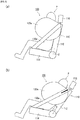
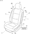
- FIG. 1 is a diagram illustrating an occupant restraining device 100 in accordance with embodiment 1 of the present invention.
- FIG. 1 illustrates the members stowed inside a seat 110 using hidden lines.
- the seat 110 is illustrated with airbags 120a and 120b not expanded and deployed.
- the occupant restraining device 100 of the present aspect is a device for restraining an occupant that is seated in the seat 110.
- the seat 110 includes a seatback 112 that supports the upper body of the occupant.
- a seat cushion 114 is provided below the seatback 112 on which the occupant sits.
- a headrest 116 is provided above the seatback 112 that supports the head of the occupant.
- the occupant restraining device 100 of embodiment 1 includes the pair of airbags 120a and 120b, a pair of tensile cloths 130a and 130b, angle detecting means 140, and internal pressure control means 150.
- the airbags 120a and 120b (side airbags) are stored in both the left and right sides of the seatback 112 of the seat 110.
- the airbags 120a and 120b expand and deploy on both sides of the occupant seated in the seat 110 during a collision or the like of the vehicle.
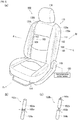
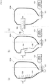
- FIG. 2 is a diagram illustrating a view of an occupant P seated in the seat 110 of FIG. 1 as viewed from the side.
- FIG. 2(a) illustrates the case where the seatback 112 is in the normal position (not reclined at all, or in other words, in a fully upright position), and
- FIG. 2(b) illustrates the case where the seatback 112 is in the reclined position. Since the left side airbag 120a and the tensile cloth 130a, and the right side airbag 120b and the tensile cloth 130b are symmetrically configured, FIG. 2 is an explanation illustrating the left side airbag 120a and the tensile cloth 130a.
- a pair of tensile cloths 130a and 130b are provided for each of the airbags 120a and 120b.
- the tensile cloths 130a and 130b are respectively stowed from inside the seatback 112 of the seat 110 to in the seat cushion 114 through the side of the stowed pair of airbags 120a and 120b opposite the occupant.
- the tensile cloth 130a deploys along the side of the seat 110 by breaking open the surface skin of the seat 110. Therefore, the tensile cloth 130a is stretched from the seatback 112 to the seat cushion 114, and the surface opposite the occupant P of the airbag 120a is retained by the tensile cloth 130a. Furthermore, the airbag 120a is then biased against the occupant P by the tensile cloth 130a, thereby enhancing the occupant restraining performance of the airbag 120a.
- the angle detecting means 140 illustrated in FIG. 1 detects the reclining angle of the seatback 112. Specifically, as illustrated in FIG. 2(a) , in a normal position where the seatback 112 is not reclined, the reclining angle ⁇ of the seatback 112 is 0. As illustrated in FIG. 2(b) , in the reclining position where the seatback 112 is inclined with respect to the seat cushion 114, the reclining angle ⁇ of the seatback 112 is a prescribed angle.
- the tensile cloth 130a when the seatback 112 is in a normal position, the tensile cloth 130a is stretched at an appropriate tension between the seatback 112 and the seat cushion 114. Therefore, the tensile cloth 130a biases the airbag 120a with an appropriate amount of force, and maintains the internal pressure of the airbag 120a at an appropriate level.
- internal pressure control means 150 is provided to control the internal pressure at the time of expansion and deployment of the airbags 120a and 120b according to the reclining angle ⁇ .
- the internal pressure control means 150 decreases the internal pressure of the airbags 120a and 120b if the reclining angle ⁇ of the seatback 112 is more than a prescribed angle during expansion and deployment of the airbags 120a and 120b.
- the internal pressure control means 150 reduces the internal pressure of the airbags 120a and 120b.
- the restraining force of the airbags 120a and 120b can be adjusted to an appropriate level, and the load on the occupant P from the airbags 120a and 120b can be greatly reduced.
- An example of the angle detecting means 140 described above is a rotation angle sensor such as an encoder and the like. By attaching a rotation angle sensor to the rotating portion of the recliner (not shown) of the seat 110, the reclining angle of the seatback 112 can be detected.
- the angle detecting means 140 is an acceleration sensor.
- An acceleration sensor is mounted to the seatback 112 to measure the distance the seatback 112 moves. Furthermore, by converting the travel distance measured into an angle, the rotation angle of the seatback 112 can be detected.
- the acceleration sensor is preferably mounted on the upper part of the seatback 112. This enables accurately detecting travel distance of the seatback 112 and thus the reclining angle.
- angle detecting means 140 is a gyro sensor.
- a gyro sensor is mounted to the seatback 112 to measure angular velocity and acceleration in three dimensions. In addition, by converting these into an angle, the reclining angle of the seatback 112 can be detected. Note, the gyro sensor can also be suitably used to detect the horizontal rotation state (rearward or sideways facing) of the seat 110.
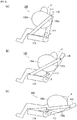
- FIG. 3 is a diagram illustrating embodiment 1 of FIG. 1 in more detail.
- FIG. 3 (a) is a diagram illustrating arrangement of dual inflators 160 in the seat 110.
- Figures 3(b) and 3(c) are diagrams illustrating variations of the dual inflator.
- the occupant restraining device 100 is provided with a dual inflator 160 including a first inflator 162 and a second inflator 164 that supply gas to the airbags 120a and 120b.
- the dual inflator 160 is arranged adjacent to the airbags 120a and 120b.
- the first inflator 162 is ignited first in an emergency and ignition of the second inflator 164 is delayed from ignition of the first inflator 162.
- the dual inflator 160a illustrated in FIG. 3 (b) is made up of a single cylindrical member.
- the first inflator 162a and the second inflator 164a are separated, and a gas discharge hole 166a is formed therebetween.
- the first inflator 162a and the second inflator 164a are each filled with a gas generating agent and each has an igniter (not shown) connected thereto.
- the gas generating agent filled in the first inflator 162a is ignited by the igniter of the first inflator 162a.
- the gas generating agent filled in the first inflator 162a becomes a gas and is ejected from the gas discharge hole 166a.
- the igniter of the second inflator 164a ignites the gas generating agent filled in the second inflator 164a.
- the gas generating agent filled in the second inflator 164a becomes a gas and is ejected from the gas discharge hole 166a.
- the first inflator 162b and the second inflator 164b each are made up of a separate cylindrical member.
- the dual inflator 160b of FIG. 3(c) has two cylindrical members.
- the first inflator 162b and the second inflator 164b are each filled with a gas generating agent and each has an igniter (not shown) connected thereto.
- the gas generating agent of the first inflator 162b is ignited first, and gas is discharged from the gas discharge hole 166c. Thereafter, ignition of the gas generating agent of the second inflator 164b is delayed, and gas is discharged from the gas discharge hole 166b. Therefore, with the dual inflator 160b as well, gas is supplied to the airbags 120a and 120b in two stages.
- FIG. 4 is a diagram illustrating another variation of the dual inflator of FIG. 3 .
- the dual inflator 160c illustrated in FIG. 4 is arranged inside the seatback 112 of the seat 110 and has a first inflator 162c and a second inflator 164c inside.
- the first inflator 162c and the second inflator 164c are separated from each other, and each inflator is filled with a gas generating agent and each has an igniter (not shown) connected thereto.
- Gas supply tubes 168a and 168b are provided in the vicinity of the airbags 120a and 120b to supply gas to the airbags 120a and 120b.
- the gas supply tubes 168a and 168b and the dual inflator 160c are connected by connecting tubes 169a and 169b.
- the gas generating agent of the first inflator 162c is ignited first. Gas is supplied to the gas supply tubes 168a and 168b through the connecting tubes 169a and 169b, and supplied to the airbags 120a and 120b through the gas supply tubes 168a and 168b. Thereafter, the gas generating agent of the second inflator 164c is then ignited after a delay. Gas is supplied to the gas supply tubes 168a and 168b through the connecting tubes 169a and 169b, and supplied to the airbags 120a and 120b through the gas supply tubes 168a and 168b. This configuration also enables gas to be supplied to the airbags 120a and 120b in two stages.
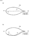
- FIG. 5 is a diagram illustrating the internal pressure curve of an airbag while the dual inflator 160 is controlled by the internal pressure control means 150 of FIG. 3 .
- FIG. 5(a) illustrates the internal pressure curve of the airbag when the reclining angle ⁇ of the seatback 112 is "0 ⁇ ⁇ ⁇ ⁇ " and the internal pressure curve of the airbag when the reclining angle ⁇ of the seatback 112 is " ⁇ ⁇ ⁇ ".
- the prescribed angle of the reclining angle ⁇ of the seatback 112 is ⁇ .
- the internal pressure control means 150 controls the internal pressure of the airbags 120a and 120b by delaying the gas discharge timing of the second inflator 164 of the dual inflator 160 from that of the first inflator 162 if the reclining angle ⁇ of the seatback 112 is more than a prescribed angle ⁇ when the airbags 120a and 120b are expanded and deployed.
- the internal pressure control means 150 sets the gas discharge timing of the first inflator 162 and the second inflator 164 of the dual inflator 160 to be the same.
- the internal pressure control means 150 delays (for example, 100 msec) the gas discharge timing of the second inflator 164.
- the tank pressure of the dual inflator 160 when the reclining angle ⁇ of the seatback 112 is " ⁇ ⁇ ⁇ " is lower than the tank pressure of the dual inflator 160 when the reclining angle ⁇ is "0 ⁇ ⁇ ⁇ ⁇ ".
- the tank pressure when the tank pressure is low, the internal pressure of the airbags 120a and 120b, to which gas is supplied from the tank (not shown) of the dual inflator 160, is naturally also low. Therefore, of the dual inflator 160, delaying the gas discharge timing of the second inflator 164 from that of the first inflator 162 can be understood to be effective in reducing the internal pressure of the airbags 120a and 120b, and thus reducing the load on the occupant P.
- FIG. 5(b) illustrates the internal pressure curve of the airbag when the reclining angle ⁇ is divided into four cases: 0 ⁇ ⁇ ⁇ ⁇ , ⁇ ⁇ ⁇ ⁇ ⁇ , ⁇ ⁇ ⁇ ⁇ ⁇ , and ⁇ ⁇ ⁇ , ( ⁇ ⁇ ⁇ ⁇ ⁇ ).
- FIG. 5(b) illustrates a case in which three prescribed angles of the reclining angle ⁇ of the seatback 112 are set. Control is provided in stages according to the level of effect on the occupant.
- the gas discharge timing of the first inflator 162 and the second inflator 164 is simultaneous.
- the gas discharge timing of the second inflator 164 is delayed by 30 msec.
- the gas discharge timing of the second inflator 164 is delayed by 50 msec.
- the gas discharge timing of the second inflator 164 is delayed by 100 msec.
- the pressure inside the airbag is reduced as the gas discharge timing of the second inflator 164 is delayed.
- a plurality of prescribed angles can be set based on the reclining angle ⁇ , and the internal pressure of the airbags 120a and 120b can be adjusted for each prescribed angle interval.
- FIG. 6 is a diagram illustrating a reclined state of the seatback 112 of FIG. 1
- FIG. 6(a) to FIG. 6(c) illustrate an occupant P seated in the seat 110 of FIG. 1 viewed from the side.
- the seatback 112 of the seat 110 illustrated in FIG. 6(a) has a reclining angle ⁇ of 0 ⁇ ⁇ ⁇ ⁇ and is positioned in a driving position.
- the seatback 112 of the seat 110 illustrated in FIG. 6(b) has a reclining angle ⁇ of ⁇ ⁇ ⁇ ⁇ ⁇ and is positioned in an intermediate reclined position.
- the seatback 112 of the seat 110 illustrated in FIG. 6(c) has a reclining angle ⁇ of ⁇ ⁇ ⁇ and is positioned at a maximum reclining angle position.
- maximum reclining angle of the present invention in this application does not include a reclining state of a seat such as a “full flat seat (a state in which the seat cushion and the seatback are connected almost horizontally to form a bed-like arrangement of seats)" found in minivans (one-box cars) and the like; rather, indicates the maximum reclining angle of a seatback at which a seat belt can perform a prescribed function for an occupant in a normal seated state while the vehicle is in motion.
- FIG. 7 is a diagram illustrating the internal pressure curve of the airbag when the dual inflator 160 is controlled by the internal pressure control means 150 based on each reclining posture of FIG. 6 .
- Selection A illustrated in FIG. 7(a) , is an internal pressure curve of the airbag when the gas discharge timing (ignition timing) of the first inflator 162 and the second inflator 164 are simultaneous.
- Selection B illustrated in FIG. 7(a) , is the internal pressure curve of the airbag when only the first inflator 162 is ignited.
- Selection C is the internal pressure curve of the airbag when the second inflator 164 is ignited at timing T1 after ignition of the first inflator 162.
- Selection D is the internal pressure curve of the airbag when the second inflator 164 is ignited at timing T2 (timing delayed from timing T1) after ignition of the first inflator 162.
- the internal pressure control means 150 refers to the reclining angle ⁇ of the seat bag 112 detected by the angle detecting means 140.
- the internal pressure control means 150 determines the reclining position of the seat bag 112 using the reclining angle ⁇ .
- the internal pressure control means 150 determines that the seatback 112 is in the driving position illustrated in FIG. 6(a) , the first inflator 162 and the second inflator 164 are ignited simultaneously. Therefore, the output of the dual inflator 160 reaches maximum output level, as shown in selection A of FIG. 7(a) , and the internal pressure of the airbags 120a and 120b reaches a maximum. Therefore, the occupant P seated in a driving position can be securely restrained.
- the internal pressure control means 150 determines that the seatback 112 is in the maximum recline angle position as illustrated in FIG. 6(c) , only the first inflator 162 is ignited. Therefore, the output of the dual inflator 160 is at the lowest output level, as shown in selection B of FIG. 7(a) , and the internal pressure of the airbags 120a and 120b reaches a minimum. Accordingly, an excessive increase in the internal pressure of the airbags 120a and 120b when the tensile cloths 130a and 130b are stretched from the seatback 112 to the seat cushion 114 is suppressed. This can significantly reduce the load on the occupant P who is seated in the maximum reclining angle position.
- the second inflator 164 should be ignited after the airbags 120a and 120b have completed expansion and deployment and have finished restraining the occupant P (for example, roughly 50 msec later).
- the internal pressure control means 150 determines that the seatback 112 is in an intermediate reclining position (between driving position and maximum reclining angle position) illustrated in FIG. 6(b) .
- the first inflator 162 is ignited first.
- the internal pressure control means 150 ignites the second inflator 164 after a delay. This results in the pressure inside the airbag of the dual inflator 160 being roughly between selection A and selection B, as illustrated in selection C and selection D. This enables controlling the internal pressure of the airbags 120a and 120b to an appropriate range and to suitably restrain the occupant P seated in an intermediate reclining position.
- the second inflator 164 is ignited at timing T1.
- the second inflator 164 is ignited at timing T2.
- the tank pressure of the dual inflator 160 can be varied by varying the timing.
- optimizing the output of the dual inflator 160 to a finer degree is feasible.
- Selection E uses a high output inflator as the first inflator 162.
- Selection F uses a low output inflator as the first inflator 162.
- the second inflator 164 is ignited at timing T3 after ignition of the first inflator 162.
- Selection G is the internal pressure curve of the airbag when only the first inflator 162 is ignited and a lower output inflator than selection B is used as the first inflator 162.
- the tank pressure of the dual inflator 160 is higher than when a low output inflator is used as the first inflator 162, as in selection F. Accordingly, even when the ignition timing of the second inflator 164 is fixed at a prescribed timing, the tank pressure of the dual inflator 160 can be varied. Thus, optimizing the output of the dual inflator 160 to a finer degree is feasible.
- Selection B and selection G also use inflators with different outputs as the first inflator 162. It can now be understood that the pressure inside the airbag can be more finely controlled by the output of the inflator, even when only the first inflator 162 is ignited, as can be seen with reference to selection B and selection G.
- the total amount of gas generating agent of the first inflator 162 and the second inflator 164 in any selection should be the same. This allows the tank pressure of the dual inflator 160 to be the same at a prescribed timing T4 when the ignition timing of the first inflator 162 and the second inflator 164 are different.
- FIG. 8 is a diagram illustrating an occupant restraining device according to embodiment 2 of the present invention.
- FIGS. 8(a) and 8(b) of the pair of airbags, a cross-sectional view of the left side airbag 220a is illustrated, and members unnecessary for explanation are not illustrated.
- the vent hole 122 is used to control the internal pressure of the airbag 220a.
- the airbag 220a has a vent hole 122 that connects the inside and outside of the airbag 220a.
- a cap 170 is fitted to the vent hole 122, and opening and closing means 172 is connected to the cap 170.
- the opening and closing means 172 is operated by a signal from the internal pressure control means 150.
- the internal pressure control means 150 controls the internal pressure of the airbag 220a by opening and closing the vent hole 122.
- the internal pressure control means 150 does not transmit a signal to the opening and closing means 172.
- the vent hole 122 is kept closed by the cap 170, as illustrated in FIG. 8(a) . Therefore, an internal pressure that is appropriate for restraining the occupant P is maintained in the airbag 220a.
- the internal pressure control means 150 transmits a signal to the opening and closing means 172.
- This causes the cap 170 to be removed from the vent hole 122 and the vent hole 122 to be opened, as illustrated in FIG. 8(b) .
- an excessive increase in the internal pressure of the airbag 220a can be suppressed. Therefore, suppressing load on the occupant P is feasible.
- embodiment 2 illustrates a configuration in which opening and closing means 172 is provided, it is not limited thereto.
- a configuration where the cap 170 is removed from the vent hole 122 when the pressure of the airbag 220a reaches a prescribed pressure is feasible.
- the internal pressure of the airbag 220a increases for an instant, but then the cap 170 is removed and gas escapes to the outside. Accordingly, the internal pressure of the airbag 220a can be reduced.
- FIG. 9 is a diagram illustrating an occupant restraining device according to embodiment 3 of the present invention.
- a cross-sectional view of the left side airbag 320a is illustrated, and members unnecessary for explanation are not illustrated.
- internal pressure control of the airbag 320a using the vent hole 122 and a tether 180 is described. Note that descriptions of elements common to embodiment 2 illustrated in FIG. 8 are omitted and the same symbols are affixed.
- the vent hole 122 is covered by a cover 184 during expansion and deployment of the airbag 320a, and the tether 180 is connected to the cover 184.
- a tether cutter 182 is arranged near the end part of the tether 180. The tether cutter 182 is operated by a signal from the internal pressure control means 150.
- the internal pressure control means 150 opens the vent hole 122 by cutting the tether 180.
- the internal pressure control means 150 does not transmit a signal to the tether cutter 182.
- the vent hole 122 is kept closed by the cover 184, as illustrated in FIG. 9(a) . Therefore, an internal pressure that is appropriate for restraining the occupant is maintained in the airbag 320a.
- the internal pressure control means 150 sends a signal to the tether cutter 182.
- the tether 180 is cut by the tether cutter 182 as illustrated in FIG. 9(b) , the cover 184 is removed from the vent hole 122, opening the vent hole 122.
- embodiment 3 illustrates a configuration in which a tether cutter 182 is provided, it is not limited thereto.
- a configuration where a weak point is formed at a midpoint of the tether 180, and when the pressure of the airbag 320a reaches a prescribed pressure, the tether 180 is broken at the weak point removing the cap 170 from the vent hole 122 is feasible.
- the internal pressure of the airbag 320a increases for an instant, but then the cap 170 is removed and gas escapes to the outside. Accordingly, the internal pressure of the airbag 320a can be reduced.
- FIG. 10 is a diagram describing another example of this embodiment.
- the occupant restraining device 200 illustrated in FIG. 10 includes cases 118a and 118b arranged on the side of the seat 110.
- Case 118a is the case where airbags 120a and 120b are stowed and case 118b is the case where tensile cloths 130a and 130b are stowed.
- the tensile cloths 130a and 130b are deployed from the case 118b to the side of the seat 110 during expansion and deployment of the airbags 120a and 120b.
- This configuration will also provide the same effects as the occupant restraining device 100 described above.
- the present invention can be used in an occupant restraining device that restrains an occupant sitting on a seat of a vehicle.
Landscapes
- Engineering & Computer Science (AREA)
- Mechanical Engineering (AREA)
- Physics & Mathematics (AREA)
- Fluid Mechanics (AREA)
- Air Bags (AREA)
Abstract
Description
- The present invention relates to an occupant restraining device that restrains an occupant sitting on a seat of a vehicle.
- Airbag devices have generally become standard equipment in vehicles in recent years. An airbag device is a safety device which is operated in case of an emergency such as a vehicle collision and, for example, expands and deploys to protect the occupant. There are various types of airbag devices depending on the installation site and application. For example, a side airbag that expands and deploys to the immediate sides of an occupant on both sides of a seat is provided in an occupant restraining device in Patent Document 1.
- In particular, in the occupant restraining device of Patent Document 1, a tensile cloth is provided that is tensioned during expansion and deployment of the airbag and extends between both sides of the airbag and the seat cushion. This allows the tensile cloth to restrict movement of the airbag away from the occupant, particularly in the left-right direction. Therefore, occupant restraining performance by the airbag can be further increased.
- [Patent Document 1]
WO 2016/039160 - The seatback of vehicle seats generally has the capability of tilting, or reclining, relative to the seat cushion. Hereinafter, the state in which the seatback is not reclined (returned fully to a non-reclined position) is called the normal position, and the seatback in a reclined position is called the reclining position.
- In a configuration provided with a tensile cloth as in Patent Document 1, the tensile cloth is stretched at an appropriate tension between the seatback and the seat cushion when the seatback is in a normal position. Therefore, the tensile cloth biases the airbag with an appropriate amount of strength, and maintains the internal pressure of the airbag at an appropriate level. In contrast, when the seatback is in the reclined position, the tensile cloth is tightly stretched between the seatback and the seat cushion, and the tension of the tensile cloth becomes high. As a result, the internal pressure of the airbag tightly biased by the tensile cloth will be high, possibly leading to significant load on the occupant.
- In light of these issues, an object of the present invention is to provide an occupant restraining device enabling significant reduction of the force of an airbag biased by a tensile cloth on an occupant in the case the seatback is in the reclining position during expansion and deployment of the airbag.
- In order to resolve the problem described above, a typical configuration of the occupant restraint device according to the present invention is an occupant restraining device for restraining an occupant seated in a seat of a vehicle, comprising:
- an airbag stowed in a seatback of the seat and expanded and deployed to a side of the occupant seated in the seat;
- a tensile cloth stowed from the seatback of the seat to the seat cushion along the stowed airbag on the side opposite the occupant;
- angle detecting means for detecting a reclining angle of the seatback;
- internal pressure control means for controlling internal pressure during expansion and deployment of the airbag according to the reclining angle;
- wherein
- the tension cloth is deployed on the side of the seat by the expansion and deployment of the airbag and is stretched from the seatback to the seat cushion to retain the surface of the airbag on the side opposite the occupant, and
- the internal pressure control means reduces the internal pressure of the airbag if the reclining angle of the seatback is a prescribed angle or more during expansion and deployment of the airbag.
- The prescribed angle described above is determined for each vehicle based on the specifications and performance required for each vehicle based on the specifications of the vehicle itself, such as the shape and rigidity, and automobile safety performance evaluation tests, such as the NCAP. This prescribed angle is, for example, an angle at which, during expansion and deployment of the airbag, the tensile cloth causes airbag internal pressure to increase and the load on the occupant to increase such that the effect of injury to the occupant cannot be ignored. This may be in multiple stages depending on the degree of effect. A prescribed angle or more indicates a state in which the seatback is further folded down from the prescribed angle described above. The seatback inclination angle when the seatback is pushed toward the front of the seat and is capable of holding the occupant, and when the seatback is most upright, is set to 0°, and from there, the angle when the seat is tipped backward is viewed as the positive direction (positive number value in the positive direction). Therefore, the inclination angle when the seatback is reclined the most is the highest value.
- With the configuration described above, if the reclining angle of the seatback is a prescribed angle or more during expansion and deployment of the airbag, the internal pressure control means reduces the internal pressure of the airbag. Thus, excessive bias of the airbag by the tensile cloth can be suppressed, and the restraining force of the airbag can be adjusted to an appropriate level. Therefore, the load on the occupant by the airbag can be significantly reduced.
- The occupant restraining device is provided with
a dual inflator comprising first and second inflators that supply gas to the airbag, wherein
the internal pressure control means controls the internal pressure of the airbag by, of the dual inflator, delaying the gas discharge timing of the second inflator from that of the first inflator. With this type of configuration, the internal pressure of the airbag is reduced compared to the case where the gas discharge timing of the first and second inflators of the dual inflator is the same. Therefore, the effects described above can favorably be obtained. - The occupant restraining device is provided with
a vent hole formed in the airbag to connect the inside and outside of the airbag, wherein
the internal pressure control means controls the internal pressure of said airbag by opening and closing the vent hole. This enables favorable adjustment in the internal pressure of the airbag by closing the vent hole when the seatback is in the normal position and opening the vent hole when the seatback is in the reclined position. - The internal pressure control means described above has a tether arranged in the airbag connected to the vent hole and can open the vent hole by cutting the tether. This enables the vent hole to be reliably opened by cutting the tether.
- The tensile cloth described above may be deployed on the side of the seat by breaking the surface skin of the seat. Alternatively, the occupant restraining device may have a case arranged on the side of the seat for stowing the airbag and the tensile cloth, and the tensile cloth may be deployed from the case to the side of the seat. With any of the configurations, the aforementioned effect can be favorably achieved.
- With the present invention, an occupant restraining device enabling significant reduction of the load of an airbag biased by a tensile cloth on an occupant in the case the seatback is in the reclining position during expansion and deployment of the airbag can be provided.
-
-
FIG. 1 is a diagram illustrating an occupant restraint device in accordance with embodiment 1 of the present invention. -
FIG. 2 is a diagram illustrating a view of an occupant P seated in the seat of -
FIG. 1 as viewed from the side. -
FIG. 3 is a diagram illustrating embodiment 1 ofFIG. 1 in more detail. -
FIG. 4 is a diagram illustrating another variation of the dual inflator ofFIG. 3 . -
FIG. 5 is a diagram illustrating an internal pressure curve of an airbag during dual inflator control by the internal pressure control means ofFIG. 3 . -
FIG. 6 is a diagram illustrating the reclining position of the seatback ofFIG. 1 . -
FIG. 7 is a diagram illustrating the internal pressure curve of the airbag when the dual inflators are controlled by the internal pressure control means at each reclining posture ofFIG. 6 . -
FIG. 8 is a diagram illustrating an occupant restraining device according to embodiment 2 of the present invention. -
FIG. 9 is a diagram illustrating an occupant restraining device according toembodiment 3 of the present invention. -
FIG. 10 is a diagram describing another example of this embodiment. - Preferred embodiments according to the present invention will hereinafter be described in detail with reference to the appended drawings. The dimensions, materials, other specific numerical values, etc. indicated in such embodiments are mere exemplifications for ease of understanding of the invention and do not limit the present invention unless otherwise noted. Note that in the present specification and drawings, elements having substantially identical functions and configurations are labeled with identical symbols in order to omit redundant descriptions along with the illustration of elements not directly related to the present invention.
- Note that regarding this embodiment, when an occupant is seated in a seat in a regular posture, the direction the occupant faces is referred to as the front, and the opposite direction is referred to as the rear. Moreover, when the occupant is seated in the seat in a regular posture, the right of the occupant is referred to as the right direction, and the left of the occupant is referred to as the left direction. Furthermore, when the occupant is seated in a regular posture, the direction towards the head of the occupant is referred to as up, and the direction towards the legs of the occupant is referred to as down. In addition, as needed, any diagrams used in descriptions below will indicate the front, rear, left, right, up, and down directions based on the occupant as described above as Fr, Rr, L, R, Up, and Down.
-
FIG. 1 is a diagram illustrating anoccupant restraining device 100 in accordance with embodiment 1 of the present invention. For ease of understanding,FIG. 1 illustrates the members stowed inside aseat 110 using hidden lines. Furthermore, inFIG. 1 , theseat 110 is illustrated withairbags - The
occupant restraining device 100 of the present aspect is a device for restraining an occupant that is seated in theseat 110. Theseat 110 includes aseatback 112 that supports the upper body of the occupant. Aseat cushion 114 is provided below theseatback 112 on which the occupant sits. Aheadrest 116 is provided above theseatback 112 that supports the head of the occupant. - As illustrated in
FIG. 1 , theoccupant restraining device 100 of embodiment 1 includes the pair ofairbags tensile cloths FIG. 1 , theairbags seatback 112 of theseat 110. Theairbags seat 110 during a collision or the like of the vehicle. -
FIG. 2 is a diagram illustrating a view of an occupant P seated in theseat 110 ofFIG. 1 as viewed from the side.FIG. 2(a) illustrates the case where theseatback 112 is in the normal position (not reclined at all, or in other words, in a fully upright position), andFIG. 2(b) illustrates the case where theseatback 112 is in the reclined position. Since theleft side airbag 120a and thetensile cloth 130a, and theright side airbag 120b and thetensile cloth 130b are symmetrically configured,FIG. 2 is an explanation illustrating theleft side airbag 120a and thetensile cloth 130a. - As illustrated in
FIG. 1 , with theoccupant restraining device 100 of the present embodiment, a pair oftensile cloths airbags tensile cloths seatback 112 of theseat 110 to in theseat cushion 114 through the side of the stowed pair ofairbags - As illustrated in
FIGS. 2(a) and 2(b) , when theairbag 120a expands and deploys, thetensile cloth 130a deploys along the side of theseat 110 by breaking open the surface skin of theseat 110. Therefore, thetensile cloth 130a is stretched from theseatback 112 to theseat cushion 114, and the surface opposite the occupant P of theairbag 120a is retained by thetensile cloth 130a. Furthermore, theairbag 120a is then biased against the occupant P by thetensile cloth 130a, thereby enhancing the occupant restraining performance of theairbag 120a. - The angle detecting means 140 illustrated in
FIG. 1 detects the reclining angle of theseatback 112. Specifically, as illustrated inFIG. 2(a) , in a normal position where theseatback 112 is not reclined, the reclining angle θ of theseatback 112 is 0. As illustrated inFIG. 2(b) , in the reclining position where theseatback 112 is inclined with respect to theseat cushion 114, the reclining angle θ of theseatback 112 is a prescribed angle. - As illustrated in
FIG. 2(a) , when theseatback 112 is in a normal position, thetensile cloth 130a is stretched at an appropriate tension between theseatback 112 and theseat cushion 114. Therefore, thetensile cloth 130a biases theairbag 120a with an appropriate amount of force, and maintains the internal pressure of theairbag 120a at an appropriate level. - As illustrated in
FIG. 2(b) , when theseatback 112 is in a reclined position, thetensile cloth 130a is tightly stretched between theseatback 112 and theseat cushion 114. Here, increase in tension of thetensile cloth 130a raises the internal pressure of theairbag 120a, which is strongly biased by thetensile cloth 130a. Therefore, load on the occupant P while being restrained by theairbag 120a may increase. - In addition, with the
occupant restraining device 100 of the present embodiment, internal pressure control means 150 is provided to control the internal pressure at the time of expansion and deployment of theairbags airbags seatback 112 is more than a prescribed angle during expansion and deployment of theairbags - With the configuration described above, if the
seatback 112 is inclined more than a prescribed angle with respect to theseat cushion 114 during expansion and deployment of theairbags airbags airbags airbags - An example of the angle detecting means 140 described above is a rotation angle sensor such as an encoder and the like. By attaching a rotation angle sensor to the rotating portion of the recliner (not shown) of the
seat 110, the reclining angle of theseatback 112 can be detected. - Another example of the angle detecting means 140 is an acceleration sensor. An acceleration sensor is mounted to the
seatback 112 to measure the distance theseatback 112 moves. Furthermore, by converting the travel distance measured into an angle, the rotation angle of theseatback 112 can be detected. Note, the acceleration sensor is preferably mounted on the upper part of theseatback 112. This enables accurately detecting travel distance of theseatback 112 and thus the reclining angle. - Further, another example of the angle detecting means 140 is a gyro sensor. A gyro sensor is mounted to the
seatback 112 to measure angular velocity and acceleration in three dimensions. In addition, by converting these into an angle, the reclining angle of theseatback 112 can be detected. Note, the gyro sensor can also be suitably used to detect the horizontal rotation state (rearward or sideways facing) of theseat 110. - An example of the internal pressure control of the
airbags FIG. 3 is a diagram illustrating embodiment 1 ofFIG. 1 in more detail.FIG. 3 (a) is a diagram illustrating arrangement ofdual inflators 160 in theseat 110.Figures 3(b) and 3(c) are diagrams illustrating variations of the dual inflator. - As illustrated in
FIG. 3(a) , in embodiment 1, theoccupant restraining device 100 is provided with adual inflator 160 including afirst inflator 162 and asecond inflator 164 that supply gas to theairbags dual inflator 160 is arranged adjacent to theairbags first inflator 162 is ignited first in an emergency and ignition of thesecond inflator 164 is delayed from ignition of thefirst inflator 162. - The
dual inflator 160a, illustrated inFIG. 3 (b) is made up of a single cylindrical member. Thefirst inflator 162a and thesecond inflator 164a are separated, and agas discharge hole 166a is formed therebetween. Thefirst inflator 162a and thesecond inflator 164a are each filled with a gas generating agent and each has an igniter (not shown) connected thereto. - Furthermore, the gas generating agent filled in the
first inflator 162a is ignited by the igniter of thefirst inflator 162a. Thus, the gas generating agent filled in thefirst inflator 162a becomes a gas and is ejected from thegas discharge hole 166a. After a delay, the igniter of thesecond inflator 164a ignites the gas generating agent filled in thesecond inflator 164a. Thus, the gas generating agent filled in thesecond inflator 164a becomes a gas and is ejected from thegas discharge hole 166a. - In the
dual inflator 160b illustrated inFIG. 3(c) , thefirst inflator 162b and thesecond inflator 164b each are made up of a separate cylindrical member. In other words, thedual inflator 160b ofFIG. 3(c) has two cylindrical members. Thefirst inflator 162b and thesecond inflator 164b are each filled with a gas generating agent and each has an igniter (not shown) connected thereto. - In the
dual inflator 160b illustrated inFIG. 3(c) as well, the gas generating agent of thefirst inflator 162b is ignited first, and gas is discharged from thegas discharge hole 166c. Thereafter, ignition of the gas generating agent of thesecond inflator 164b is delayed, and gas is discharged from thegas discharge hole 166b. Therefore, with thedual inflator 160b as well, gas is supplied to theairbags -
FIG. 4 is a diagram illustrating another variation of the dual inflator ofFIG. 3 . Thedual inflator 160c illustrated inFIG. 4 is arranged inside theseatback 112 of theseat 110 and has afirst inflator 162c and asecond inflator 164c inside. Thefirst inflator 162c and thesecond inflator 164c are separated from each other, and each inflator is filled with a gas generating agent and each has an igniter (not shown) connected thereto.Gas supply tubes airbags airbags gas supply tubes dual inflator 160c are connected by connectingtubes - With the
dual inflator 160c ofFIG. 4 , the gas generating agent of thefirst inflator 162c is ignited first. Gas is supplied to thegas supply tubes tubes airbags gas supply tubes second inflator 164c is then ignited after a delay. Gas is supplied to thegas supply tubes tubes airbags gas supply tubes airbags -
FIG. 5 is a diagram illustrating the internal pressure curve of an airbag while thedual inflator 160 is controlled by the internal pressure control means 150 ofFIG. 3 .FIG. 5(a) illustrates the internal pressure curve of the airbag when the reclining angle θ of theseatback 112 is "0 < θ < α" and the internal pressure curve of the airbag when the reclining angle θ of theseatback 112 is "α ≤ θ". In other words, inFIG. 5(a) , the prescribed angle of the reclining angle θ of theseatback 112 is α. The internal pressure control means 150 controls the internal pressure of theairbags second inflator 164 of thedual inflator 160 from that of thefirst inflator 162 if the reclining angle θ of theseatback 112 is more than a prescribed angle α when theairbags - When the reclining angle θ of the
seatback 112 is "0 < θ < α", the internal pressure control means 150 sets the gas discharge timing of thefirst inflator 162 and thesecond inflator 164 of thedual inflator 160 to be the same. On the other hand, of thefirst inflator 162 andsecond inflator 164 of thedual inflator 160, when the reclining angle θ of theseatback 112 is "α ≤ θ", the internal pressure control means 150 delays (for example, 100 msec) the gas discharge timing of thesecond inflator 164. - The tank pressure of the
dual inflator 160 when the reclining angle θ of theseatback 112 is "α ≤ θ" is lower than the tank pressure of thedual inflator 160 when the reclining angle θ is "0 < θ < α". As is apparent with reference toFIG. 5(a) , when the tank pressure is low, the internal pressure of theairbags dual inflator 160, is naturally also low. Therefore, of thedual inflator 160, delaying the gas discharge timing of thesecond inflator 164 from that of thefirst inflator 162 can be understood to be effective in reducing the internal pressure of theairbags -
Figure 5(b) illustrates the internal pressure curve of the airbag when the reclining angle θ is divided into four cases: 0 < θ < α, α ≤ θ < β, β ≤ θ < τ, and τ ≤ θ, (α < β < τ). In other words,FIG. 5(b) illustrates a case in which three prescribed angles of the reclining angle θ of theseatback 112 are set. Control is provided in stages according to the level of effect on the occupant. - When the reclining angle is "0 < θ < α", the gas discharge timing of the
first inflator 162 and thesecond inflator 164 is simultaneous. When the reclining angle is "α ≤ θ < β", the gas discharge timing of thesecond inflator 164 is delayed by 30 msec. When the reclining angle is "β ≤ θ < τ", the gas discharge timing of thesecond inflator 164 is delayed by 50 msec. When the reclining angle θ is "τ ≤ θ", the gas discharge timing of thesecond inflator 164 is delayed by 100 msec. The gas discharge timing described above can be arbitrarily determined based on inflator characteristics and restraint system specifications. - As is apparent in
FIG. 5(b) , the pressure inside the airbag is reduced as the gas discharge timing of thesecond inflator 164 is delayed. Thus, it can be understood that a plurality of prescribed angles (threshold values) can be set based on the reclining angle θ, and the internal pressure of theairbags -
FIG. 6 is a diagram illustrating a reclined state of theseatback 112 ofFIG. 1 , andFIG. 6(a) to FIG. 6(c) illustrate an occupant P seated in theseat 110 ofFIG. 1 viewed from the side. Theseatback 112 of theseat 110 illustrated inFIG. 6(a) has a reclining angle θ of 0 < θ < α and is positioned in a driving position. - The
seatback 112 of theseat 110 illustrated inFIG. 6(b) has a reclining angle θ of α ≤ θ < β and is positioned in an intermediate reclined position. Theseatback 112 of theseat 110 illustrated inFIG. 6(c) has a reclining angle θ of β ≤ θ and is positioned at a maximum reclining angle position. - The term "maximum reclining angle" of the present invention in this application does not include a reclining state of a seat such as a "full flat seat (a state in which the seat cushion and the seatback are connected almost horizontally to form a bed-like arrangement of seats)" found in minivans (one-box cars) and the like; rather, indicates the maximum reclining angle of a seatback at which a seat belt can perform a prescribed function for an occupant in a normal seated state while the vehicle is in motion.
-
FIG. 7 is a diagram illustrating the internal pressure curve of the airbag when thedual inflator 160 is controlled by the internal pressure control means 150 based on each reclining posture ofFIG. 6 . Selection A, illustrated inFIG. 7(a) , is an internal pressure curve of the airbag when the gas discharge timing (ignition timing) of thefirst inflator 162 and thesecond inflator 164 are simultaneous. Selection B, illustrated inFIG. 7(a) , is the internal pressure curve of the airbag when only thefirst inflator 162 is ignited. - Selection C, illustrated in
FIG. 7(a) , is the internal pressure curve of the airbag when thesecond inflator 164 is ignited at timing T1 after ignition of thefirst inflator 162. Selection D, illustrated inFIG. 7(a) , is the internal pressure curve of the airbag when thesecond inflator 164 is ignited at timing T2 (timing delayed from timing T1) after ignition of thefirst inflator 162. - In the
occupant restraining device 100 of embodiment 1, the internal pressure control means 150 refers to the reclining angle θ of theseat bag 112 detected by theangle detecting means 140. The internal pressure control means 150 determines the reclining position of theseat bag 112 using the reclining angle θ. - When the internal pressure control means 150 determines that the
seatback 112 is in the driving position illustrated inFIG. 6(a) , thefirst inflator 162 and thesecond inflator 164 are ignited simultaneously. Therefore, the output of thedual inflator 160 reaches maximum output level, as shown in selection A ofFIG. 7(a) , and the internal pressure of theairbags - When the internal pressure control means 150 determines that the
seatback 112 is in the maximum recline angle position as illustrated inFIG. 6(c) , only thefirst inflator 162 is ignited. Therefore, the output of thedual inflator 160 is at the lowest output level, as shown in selection B ofFIG. 7(a) , and the internal pressure of theairbags airbags tensile cloths seatback 112 to theseat cushion 114 is suppressed. This can significantly reduce the load on the occupant P who is seated in the maximum reclining angle position. - In the case where only the
first inflator 162 is ignited (when used) as described above, thesecond inflator 164 should be ignited after theairbags - When the internal pressure control means 150 determines that the
seatback 112 is in an intermediate reclining position (between driving position and maximum reclining angle position) illustrated inFIG. 6(b) , thefirst inflator 162 is ignited first. Thereafter, the internal pressure control means 150 ignites thesecond inflator 164 after a delay. This results in the pressure inside the airbag of thedual inflator 160 being roughly between selection A and selection B, as illustrated in selection C and selection D. This enables controlling the internal pressure of theairbags - In particular, in selection C, illustrated in
FIG. 7(a) , thesecond inflator 164 is ignited at timing T1. In selection D, thesecond inflator 164 is ignited at timing T2. Thus, even when the samesecond inflator 164 is used, the tank pressure of thedual inflator 160 can be varied by varying the timing. Thus, optimizing the output of thedual inflator 160 to a finer degree is feasible. - Selection E, illustrated in
FIG. 7(b) , uses a high output inflator as thefirst inflator 162. Selection F, illustrated inFIG. 7(b) , uses a low output inflator as thefirst inflator 162. In selection E and selection F, thesecond inflator 164 is ignited at timing T3 after ignition of thefirst inflator 162. Selection G, illustrated inFIG. 7(b) , is the internal pressure curve of the airbag when only thefirst inflator 162 is ignited and a lower output inflator than selection B is used as thefirst inflator 162. - When a high output inflator is used as the
first inflator 162, as in selection E, the tank pressure of thedual inflator 160 is higher than when a low output inflator is used as thefirst inflator 162, as in selection F. Accordingly, even when the ignition timing of thesecond inflator 164 is fixed at a prescribed timing, the tank pressure of thedual inflator 160 can be varied. Thus, optimizing the output of thedual inflator 160 to a finer degree is feasible. - Selection B and selection G also use inflators with different outputs as the
first inflator 162. It can now be understood that the pressure inside the airbag can be more finely controlled by the output of the inflator, even when only thefirst inflator 162 is ignited, as can be seen with reference to selection B and selection G. - Note, in the case of igniting the
first inflator 162 and thesecond inflator 164 as in selection A, selection E and selection F, the total amount of gas generating agent of thefirst inflator 162 and thesecond inflator 164 in any selection should be the same. This allows the tank pressure of thedual inflator 160 to be the same at a prescribed timing T4 when the ignition timing of thefirst inflator 162 and thesecond inflator 164 are different. -
FIG. 8 is a diagram illustrating an occupant restraining device according to embodiment 2 of the present invention. InFIGS. 8(a) and 8(b) , of the pair of airbags, a cross-sectional view of theleft side airbag 220a is illustrated, and members unnecessary for explanation are not illustrated. - In embodiment 2, the
vent hole 122 is used to control the internal pressure of theairbag 220a. As illustrated inFIG. 8(a) , theairbag 220a has avent hole 122 that connects the inside and outside of theairbag 220a. Acap 170 is fitted to thevent hole 122, and opening and closing means 172 is connected to thecap 170. The opening and closing means 172 is operated by a signal from the internal pressure control means 150. - In embodiment 2, the internal pressure control means 150 controls the internal pressure of the
airbag 220a by opening and closing thevent hole 122. In detail, for example, when the reclining angle θ is "0 < θ < α" (the reclining angle θ of theseatback 112 is less than the prescribed angle α), the internal pressure control means 150 does not transmit a signal to the opening and closing means 172. Hereby, thevent hole 122 is kept closed by thecap 170, as illustrated inFIG. 8(a) . Therefore, an internal pressure that is appropriate for restraining the occupant P is maintained in theairbag 220a. - On the other hand, if the reclining angle θ of the
seatback 112 is "α ≤ θ" (the reclining angle θ of theseatback 112 is the prescribed angle α or more), the internal pressure control means 150 transmits a signal to the opening and closing means 172. This causes thecap 170 to be removed from thevent hole 122 and thevent hole 122 to be opened, as illustrated inFIG. 8(b) . Thereby, an excessive increase in the internal pressure of theairbag 220a can be suppressed. Therefore, suppressing load on the occupant P is feasible. - Although embodiment 2 illustrates a configuration in which opening and closing means 172 is provided, it is not limited thereto. For example, a configuration where the
cap 170 is removed from thevent hole 122 when the pressure of theairbag 220a reaches a prescribed pressure is feasible. With this type of configuration, the internal pressure of theairbag 220a increases for an instant, but then thecap 170 is removed and gas escapes to the outside. Accordingly, the internal pressure of theairbag 220a can be reduced. -
FIG. 9 is a diagram illustrating an occupant restraining device according toembodiment 3 of the present invention. InFIG. 9 as well, a cross-sectional view of theleft side airbag 320a is illustrated, and members unnecessary for explanation are not illustrated. Inembodiment 3, internal pressure control of theairbag 320a using thevent hole 122 and atether 180 is described. Note that descriptions of elements common to embodiment 2 illustrated inFIG. 8 are omitted and the same symbols are affixed. - As illustrated in
FIG. 9(a) , thevent hole 122 is covered by acover 184 during expansion and deployment of theairbag 320a, and thetether 180 is connected to thecover 184. Atether cutter 182 is arranged near the end part of thetether 180. Thetether cutter 182 is operated by a signal from the internal pressure control means 150. - In
embodiment 3, the internal pressure control means 150 opens thevent hole 122 by cutting thetether 180. In detail, when the reclining angle θ of theseatback 112 is "0 < θ < α", the internal pressure control means 150 does not transmit a signal to thetether cutter 182. Therewith, thevent hole 122 is kept closed by thecover 184, as illustrated inFIG. 9(a) . Therefore, an internal pressure that is appropriate for restraining the occupant is maintained in theairbag 320a. - On the other hand, if the reclining angle θ of the
seatback 112 is "α ≤ θ", the internal pressure control means 150 sends a signal to thetether cutter 182. Therewith, thetether 180 is cut by thetether cutter 182 as illustrated inFIG. 9(b) , thecover 184 is removed from thevent hole 122, opening thevent hole 122. - Thereafter, as illustrated in
FIG. 9(c) , the gas from theairbag 320a flows outwardly through thevent hole 122, pushing thecover 184 andtether 180 outwardly from theairbag 320a. With this configuration, an excessive increase in the internal pressure of theairbag 320a can be suppressed. Therefore, suppressing load on the occupant P is feasible. - Although
embodiment 3 illustrates a configuration in which atether cutter 182 is provided, it is not limited thereto. For example, a configuration where a weak point is formed at a midpoint of thetether 180, and when the pressure of theairbag 320a reaches a prescribed pressure, thetether 180 is broken at the weak point removing thecap 170 from thevent hole 122 is feasible. With this type of configuration, the internal pressure of theairbag 320a increases for an instant, but then thecap 170 is removed and gas escapes to the outside. Accordingly, the internal pressure of theairbag 320a can be reduced. -
FIG. 10 is a diagram describing another example of this embodiment. Theoccupant restraining device 200 illustrated inFIG. 10 includescases seat 110.Case 118a is the case whereairbags case 118b is the case wheretensile cloths occupant restraining device 200 illustrated inFIG. 10 , thetensile cloths case 118b to the side of theseat 110 during expansion and deployment of theairbags occupant restraining device 100 described above. - Preferred examples of the present invention were described above while referring to the accompanying drawings. However, the embodiments described above are preferred examples of the present invention, and other embodiments can be implemented or performed by various methods. In particular, unless described otherwise in the specification of the present application, the invention is not restricted to the shape, size, configurational disposition, and the like of parts illustrated in detail in the accompanying drawings. Furthermore, expressions and terms used in the specification of the present application are used for providing a description, and the invention is not limited thereto, unless specifically described otherwise.
- Therefore, it is obvious that a person with ordinary skill in the art can conceive of various changed examples or modified examples within the scope described in the scope of the claims, which is understood to naturally belong to the technical scope of the present invention.
- The present invention can be used in an occupant restraining device that restrains an occupant sitting on a seat of a vehicle.
- 100...occupant restraining device, 110...seat, 112...seatback, 114...seat cushion, 116...headrest, 118a, 118b...case, 120a, 220a, 320a...airbag, 120b...airbag, 122...vent hole, 130a...tensile cloth, 130b...tensile cloth, 140...angle detecting means, 150...internal pressure control means, 160, 160a, 160b, 160c...dual inflator, 162, 162a, 162b, 162c...first inflator, 164, 164a, 164b, 164c...second inflator, 166a, 166b, 166c...gas discharge holes, 168a, 168b...gas supply tubes, 169a, 169b...connecting
tubes 169b...connectingtubes 170...cap, 172...opening and closing means, 180...tether, 182...tether cutter, 200...occupant restraining device, P ...occupant
Claims (6)
- An occupant restraining device that restrains an occupant sitting on a seat of a vehicle, comprising:an airbag stowed in the seatback of the seat that expands and deploys to the side of an occupant seated in the seat;a tensile cloth stowed from within the seatback of the seat to within the seat cushion along the side of the airbag, on the side opposite the occupant;an angle detecting means that detects the reclining angle of the seatback,internal pressure control means for controlling the internal pressure of the airbag during expansion and deployment according to the reclining angle, whereinthe tensile cloth is deployed along the side of the seat on the side opposite the occupant by the expansion and deployment of the airbag by breaking the surface skin of the seat, and is stretched from the seatback to the seat cushion to retain the surface of the airbag, andthe internal pressure control means decreases the internal pressure of the airbag if the reclining angle of the seatback is more than a prescribed angle during expansion and deployment of the airbag.
- The occupant restraining device according to claim 1, comprising:a dual inflator including first and second inflators that supply gas to the airbag, whereinthe internal pressure control means controls the internal pressure of the airbag by, of the dual inflator, delaying the gas discharge timing of the second inflator from that of the first inflator.
- The occupant restraining device according to claim 1, comprising a vent hole formed in the airbag to connect the inside and outside of the airbag, wherein
the internal pressure control means controls the internal pressure of the airbag by opening and closing the vent hole. - The occupant restraining device according to claim 3, wherein the internal pressure control means has a tether arranged in the airbag connected to the vent hole and opens the vent hole by cutting the tether.
- The occupant restraining device according to any one of claims 1 to 4, wherein the tensile cloth is deployed on the side of the seat by breaking open the surface skin of the seat.
- The occupant restraining device according to any one of claims 1 to 4, comprising:a case in which the airbag and tensile cloth are stowed, arranged on the side of the seat, whereinthe tensile cloth deploys from the case along the side of the seat.
Applications Claiming Priority (2)
| Application Number | Priority Date | Filing Date | Title |
|---|---|---|---|
| JP2018194381 | 2018-10-15 | ||
| PCT/JP2019/040532 WO2020080374A1 (en) | 2018-10-15 | 2019-10-15 | Vehicle occupant restraining device |
Publications (3)
| Publication Number | Publication Date |
|---|---|
| EP3868614A1 true EP3868614A1 (en) | 2021-08-25 |
| EP3868614A4 EP3868614A4 (en) | 2022-05-04 |
| EP3868614B1 EP3868614B1 (en) | 2024-02-28 |
Family
ID=70283797
Family Applications (1)
| Application Number | Title | Priority Date | Filing Date |
|---|---|---|---|
| EP19873930.2A Active EP3868614B1 (en) | 2018-10-15 | 2019-10-15 | Vehicle occupant restraining device |
Country Status (6)
| Country | Link |
|---|---|
| US (1) | US11447086B2 (en) |
| EP (1) | EP3868614B1 (en) |
| JP (1) | JP7045478B2 (en) |
| KR (1) | KR102572112B1 (en) |
| CN (1) | CN112805190B (en) |
| WO (1) | WO2020080374A1 (en) |
Cited By (1)
| Publication number | Priority date | Publication date | Assignee | Title |
|---|---|---|---|---|
| DE112021001169B4 (en) * | 2020-02-21 | 2024-05-29 | Daicel Corporation | Coupling structure, airbag device and vehicle seat |
Families Citing this family (10)
| Publication number | Priority date | Publication date | Assignee | Title |
|---|---|---|---|---|
| DE102017218338A1 (en) * | 2017-10-13 | 2019-04-18 | Bayerische Motoren Werke Aktiengesellschaft | AIRBAG ARRANGEMENT FOR A VEHICLE SEAT OF A MOTOR VEHICLE |
| DE102019107364A1 (en) * | 2019-03-22 | 2020-09-24 | Audi Ag | Side gas bag module, vehicle seat and vehicle |
| JP7261886B2 (en) * | 2019-08-09 | 2023-04-20 | オートリブ ディベロップメント エービー | Airbag device, vehicle seat, and method of igniting airbag device |
| KR102792230B1 (en) * | 2019-10-23 | 2025-04-07 | 현대자동차주식회사 | Side air bag for vehicle |
| JP7498048B2 (en) * | 2020-07-14 | 2024-06-11 | 株式会社ダイセル | Vehicle seat and passenger restraint device |
| CN116194344A (en) * | 2020-10-09 | 2023-05-30 | 奥托立夫开发公司 | Airbag device |
| JP7411115B2 (en) * | 2020-11-05 | 2024-01-10 | オートリブ ディベロップメント エービー | air bag device |
| US11260820B1 (en) * | 2020-11-30 | 2022-03-01 | Ford Global Technologies, Llc | Side airbag with adaptive positioning for reclining seat |
| JP2024003651A (en) * | 2022-06-27 | 2024-01-15 | 豊田合成株式会社 | Occupant protection device |
| US12151636B1 (en) * | 2023-06-15 | 2024-11-26 | Ford Global Technologies, Llc | Seat airbag assembly |
Family Cites Families (29)
| Publication number | Priority date | Publication date | Assignee | Title |
|---|---|---|---|---|
| DE19845992A1 (en) | 1997-09-04 | 1999-05-20 | Inova Gmbh Tech Entwicklungen | Side airbag system with at least one inflatable airbag and support belt stretchable in bag region |
| US6029993A (en) * | 1997-10-06 | 2000-02-29 | Inova Gmbh Technische Entwicklungen | Side airbag device, method for operation thereof and vehicle seat therewith |
| US6616184B2 (en) * | 2001-04-25 | 2003-09-09 | Trw Vehicle Safety Systems Inc. | Vehicle occupant protection apparatus with inflation volume and shape control |
| JP4206291B2 (en) * | 2002-07-08 | 2009-01-07 | 本田技研工業株式会社 | Side airbag device |
| KR100513879B1 (en) * | 2003-08-08 | 2005-09-09 | 현대자동차주식회사 | Method for Expansion Pressure Control of Assistant Seat Airbag |
| US7866696B2 (en) * | 2004-12-10 | 2011-01-11 | GM Global Technology Operations LLC | Vehicle seat assembly |
| US7552942B2 (en) * | 2005-06-23 | 2009-06-30 | Trw Vehicle Safety Systems Inc. | Vehicle occupant protection apparatus having vent member that is controlled by a releasable tether |
| JP4506630B2 (en) * | 2005-09-26 | 2010-07-21 | 豊田合成株式会社 | Side airbag device for rear seats |
| KR20070060569A (en) * | 2005-12-09 | 2007-06-13 | 현대자동차주식회사 | Passenger seat airbag deployment control method |
| JP5109517B2 (en) * | 2007-07-24 | 2012-12-26 | マツダ株式会社 | Vehicle occupant protection device |
| JP2009241643A (en) * | 2008-03-28 | 2009-10-22 | Nippon Plast Co Ltd | Airbag device |
| JP5776616B2 (en) | 2012-04-16 | 2015-09-09 | トヨタ自動車株式会社 | Vehicle seat |
| US8646808B2 (en) * | 2012-06-18 | 2014-02-11 | Autoliv Asp, Inc. | Airbag with active vent |
| JP5781985B2 (en) * | 2012-07-05 | 2015-09-24 | オートリブ ディベロップメント エービー | Side airbag device |
| JP5594327B2 (en) * | 2012-07-10 | 2014-09-24 | トヨタ自動車株式会社 | Vehicle seat |
| JP5776648B2 (en) | 2012-08-10 | 2015-09-09 | トヨタ自動車株式会社 | Crew protection device |
| DE102012016460B4 (en) * | 2012-08-18 | 2018-10-18 | Autoliv Development Ab | Airbag module with an adaptive influencing device |
| JP2014121924A (en) * | 2012-12-20 | 2014-07-03 | Toyota Motor Corp | Occupant restraint system for vehicle |
| WO2016039160A1 (en) | 2014-09-08 | 2016-03-17 | オートリブ ディベロップメント エービー | Vehicle occupant restraint device |
| KR101646349B1 (en) * | 2014-10-07 | 2016-08-08 | 현대자동차주식회사 | Rear seat air-bag apparatus and controlling method thereof for vehicle |
| JP6197815B2 (en) * | 2015-03-19 | 2017-09-20 | トヨタ自動車株式会社 | Occupant protection control device, occupant protection control program, and vehicle |
| KR101724944B1 (en) * | 2015-11-06 | 2017-04-10 | 현대자동차주식회사 | Airbag system of vehicle |
| KR101621960B1 (en) | 2016-01-29 | 2016-06-01 | 존슨콘트롤즈 오토모티브 인테리어 코리아 주식회사 | Apparatus for aligning stitch line on armrest of doortrim for vehicle using rotatable leather fixing device with limited rotation range |
| JP6402136B2 (en) * | 2016-05-17 | 2018-10-10 | オートリブ ディベロップメント エービー | Side airbag device |
| KR102098372B1 (en) | 2016-05-20 | 2020-04-07 | 오토리브 디벨로프먼트 에이비 | Side airbag device |
| JP6688717B2 (en) * | 2016-10-06 | 2020-04-28 | アイシン精機株式会社 | Vehicle seat device and vehicle seat air pressure control method |
| US11491941B2 (en) * | 2017-03-16 | 2022-11-08 | Honda Motor Co., Ltd. | Vehicle occupant protection control device, vehicle occupant protection control method, and program |
| KR102478088B1 (en) * | 2017-10-16 | 2022-12-16 | 현대자동차주식회사 | Variable control apparatus for airbag of vehicle |
| CN111347993A (en) * | 2018-12-21 | 2020-06-30 | 富顶精密组件(深圳)有限公司 | Driving safety auxiliary system and detection method |
-
2019
- 2019-10-15 KR KR1020217011075A patent/KR102572112B1/en active Active
- 2019-10-15 US US17/285,353 patent/US11447086B2/en active Active
- 2019-10-15 WO PCT/JP2019/040532 patent/WO2020080374A1/en not_active Ceased
- 2019-10-15 EP EP19873930.2A patent/EP3868614B1/en active Active
- 2019-10-15 CN CN201980065405.4A patent/CN112805190B/en active Active
- 2019-10-15 JP JP2020553209A patent/JP7045478B2/en active Active
Cited By (1)
| Publication number | Priority date | Publication date | Assignee | Title |
|---|---|---|---|---|
| DE112021001169B4 (en) * | 2020-02-21 | 2024-05-29 | Daicel Corporation | Coupling structure, airbag device and vehicle seat |
Also Published As
| Publication number | Publication date |
|---|---|
| US11447086B2 (en) | 2022-09-20 |
| JP7045478B2 (en) | 2022-03-31 |
| KR20210088543A (en) | 2021-07-14 |
| WO2020080374A1 (en) | 2020-04-23 |
| KR102572112B1 (en) | 2023-08-29 |
| EP3868614A4 (en) | 2022-05-04 |
| US20210370861A1 (en) | 2021-12-02 |
| CN112805190B (en) | 2023-04-04 |
| JPWO2020080374A1 (en) | 2021-09-02 |
| EP3868614B1 (en) | 2024-02-28 |
| CN112805190A (en) | 2021-05-14 |
Similar Documents
| Publication | Publication Date | Title |
|---|---|---|
| EP3868614B1 (en) | Vehicle occupant restraining device | |
| KR102614143B1 (en) | Frontal airbag for vehicle and airbag deployment system using same | |
| US9751491B2 (en) | Side airbag device | |
| KR102833529B1 (en) | Side airbag device | |
| CN113002475B (en) | Side airbag device | |
| WO2020255817A1 (en) | Side airbag device | |
| JP7408507B2 (en) | Occupant protection device | |
| US11745694B2 (en) | Airbag device, vehicle seat, and ignition method for airbag device | |
| WO2021100382A1 (en) | Airbag device | |
| JP2015080969A (en) | Airbag device | |
| US20200307491A1 (en) | Occupant protection apparatus | |
| US10723307B2 (en) | Airbag module | |
| CN110871765A (en) | Airbag device | |
| JP6960236B2 (en) | Vehicle occupant protection device | |
| JP2023120093A (en) | Rear seat airbag and rear seat airbag device | |
| JP2008062714A (en) | Crew protection device for vehicle | |
| JP3584773B2 (en) | Airbag deployment control device | |
| JP6958454B2 (en) | Vehicle occupant protection device | |
| JP5549577B2 (en) | Side airbag device for rear seats | |
| JP6871787B2 (en) | Vehicle occupant protection device | |
| JP2010247661A (en) | Crew protection device | |
| JP4355153B2 (en) | Vehicle airbag device | |
| JP4470866B2 (en) | Vehicle occupant protection device and control method therefor | |
| JP2013112220A (en) | Vehicle occupant restraining device | |
| JP3956729B2 (en) | Vehicle airbag device |
Legal Events
| Date | Code | Title | Description |
|---|---|---|---|
| STAA | Information on the status of an ep patent application or granted ep patent |
Free format text: STATUS: THE INTERNATIONAL PUBLICATION HAS BEEN MADE |
|
| PUAI | Public reference made under article 153(3) epc to a published international application that has entered the european phase |
Free format text: ORIGINAL CODE: 0009012 |
|
| STAA | Information on the status of an ep patent application or granted ep patent |
Free format text: STATUS: REQUEST FOR EXAMINATION WAS MADE |
|
| 17P | Request for examination filed |
Effective date: 20210413 |
|
| AK | Designated contracting states |
Kind code of ref document: A1 Designated state(s): AL AT BE BG CH CY CZ DE DK EE ES FI FR GB GR HR HU IE IS IT LI LT LU LV MC MK MT NL NO PL PT RO RS SE SI SK SM TR |
|
| DAV | Request for validation of the european patent (deleted) | ||
| DAX | Request for extension of the european patent (deleted) | ||
| A4 | Supplementary search report drawn up and despatched |
Effective date: 20220404 |
|
| RIC1 | Information provided on ipc code assigned before grant |
Ipc: B60R 21/276 20060101ALN20220328BHEP Ipc: B60R 21/231 20110101ALN20220328BHEP Ipc: B60R 21/239 20060101ALI20220328BHEP Ipc: B60R 21/2338 20110101ALI20220328BHEP Ipc: B60R 21/207 20060101ALI20220328BHEP Ipc: B60R 21/26 20110101AFI20220328BHEP |
|
| STAA | Information on the status of an ep patent application or granted ep patent |
Free format text: STATUS: EXAMINATION IS IN PROGRESS |
|
| 17Q | First examination report despatched |
Effective date: 20221220 |
|
| GRAP | Despatch of communication of intention to grant a patent |
Free format text: ORIGINAL CODE: EPIDOSNIGR1 |
|
| RIC1 | Information provided on ipc code assigned before grant |
Ipc: B60R 21/276 20060101ALN20230804BHEP Ipc: B60R 21/231 20110101ALN20230804BHEP Ipc: B60R 21/239 20060101ALI20230804BHEP Ipc: B60R 21/2338 20110101ALI20230804BHEP Ipc: B60R 21/207 20060101ALI20230804BHEP Ipc: B60R 21/26 20110101AFI20230804BHEP |
|
| STAA | Information on the status of an ep patent application or granted ep patent |
Free format text: STATUS: GRANT OF PATENT IS INTENDED |
|
| INTG | Intention to grant announced |
Effective date: 20230914 |
|
| GRAS | Grant fee paid |
Free format text: ORIGINAL CODE: EPIDOSNIGR3 |
|
| GRAA | (expected) grant |
Free format text: ORIGINAL CODE: 0009210 |
|
| STAA | Information on the status of an ep patent application or granted ep patent |
Free format text: STATUS: THE PATENT HAS BEEN GRANTED |
|
| AK | Designated contracting states |
Kind code of ref document: B1 Designated state(s): AL AT BE BG CH CY CZ DE DK EE ES FI FR GB GR HR HU IE IS IT LI LT LU LV MC MK MT NL NO PL PT RO RS SE SI SK SM TR |
|
| REG | Reference to a national code |
Ref country code: GB Ref legal event code: FG4D |
|
| REG | Reference to a national code |
Ref country code: CH Ref legal event code: EP |
|
| REG | Reference to a national code |
Ref country code: DE Ref legal event code: R096 Ref document number: 602019047518 Country of ref document: DE |
|
| REG | Reference to a national code |
Ref country code: IE Ref legal event code: FG4D |
|
| REG | Reference to a national code |
Ref country code: LT Ref legal event code: MG9D |
|
| PG25 | Lapsed in a contracting state [announced via postgrant information from national office to epo] |
Ref country code: IS Free format text: LAPSE BECAUSE OF FAILURE TO SUBMIT A TRANSLATION OF THE DESCRIPTION OR TO PAY THE FEE WITHIN THE PRESCRIBED TIME-LIMIT Effective date: 20240628 |
|
| REG | Reference to a national code |
Ref country code: NL Ref legal event code: MP Effective date: 20240228 |
|
| PG25 | Lapsed in a contracting state [announced via postgrant information from national office to epo] |
Ref country code: LT Free format text: LAPSE BECAUSE OF FAILURE TO SUBMIT A TRANSLATION OF THE DESCRIPTION OR TO PAY THE FEE WITHIN THE PRESCRIBED TIME-LIMIT Effective date: 20240228 |
|
| PG25 | Lapsed in a contracting state [announced via postgrant information from national office to epo] |
Ref country code: GR Free format text: LAPSE BECAUSE OF FAILURE TO SUBMIT A TRANSLATION OF THE DESCRIPTION OR TO PAY THE FEE WITHIN THE PRESCRIBED TIME-LIMIT Effective date: 20240529 |
|
| PG25 | Lapsed in a contracting state [announced via postgrant information from national office to epo] |
Ref country code: HR Free format text: LAPSE BECAUSE OF FAILURE TO SUBMIT A TRANSLATION OF THE DESCRIPTION OR TO PAY THE FEE WITHIN THE PRESCRIBED TIME-LIMIT Effective date: 20240228 Ref country code: RS Free format text: LAPSE BECAUSE OF FAILURE TO SUBMIT A TRANSLATION OF THE DESCRIPTION OR TO PAY THE FEE WITHIN THE PRESCRIBED TIME-LIMIT Effective date: 20240528 Ref country code: NL Free format text: LAPSE BECAUSE OF FAILURE TO SUBMIT A TRANSLATION OF THE DESCRIPTION OR TO PAY THE FEE WITHIN THE PRESCRIBED TIME-LIMIT Effective date: 20240228 |
|
| PG25 | Lapsed in a contracting state [announced via postgrant information from national office to epo] |
Ref country code: ES Free format text: LAPSE BECAUSE OF FAILURE TO SUBMIT A TRANSLATION OF THE DESCRIPTION OR TO PAY THE FEE WITHIN THE PRESCRIBED TIME-LIMIT Effective date: 20240228 |
|
| PG25 | Lapsed in a contracting state [announced via postgrant information from national office to epo] |
Ref country code: RS Free format text: LAPSE BECAUSE OF FAILURE TO SUBMIT A TRANSLATION OF THE DESCRIPTION OR TO PAY THE FEE WITHIN THE PRESCRIBED TIME-LIMIT Effective date: 20240528 Ref country code: NO Free format text: LAPSE BECAUSE OF FAILURE TO SUBMIT A TRANSLATION OF THE DESCRIPTION OR TO PAY THE FEE WITHIN THE PRESCRIBED TIME-LIMIT Effective date: 20240528 Ref country code: NL Free format text: LAPSE BECAUSE OF FAILURE TO SUBMIT A TRANSLATION OF THE DESCRIPTION OR TO PAY THE FEE WITHIN THE PRESCRIBED TIME-LIMIT Effective date: 20240228 Ref country code: LT Free format text: LAPSE BECAUSE OF FAILURE TO SUBMIT A TRANSLATION OF THE DESCRIPTION OR TO PAY THE FEE WITHIN THE PRESCRIBED TIME-LIMIT Effective date: 20240228 Ref country code: IS Free format text: LAPSE BECAUSE OF FAILURE TO SUBMIT A TRANSLATION OF THE DESCRIPTION OR TO PAY THE FEE WITHIN THE PRESCRIBED TIME-LIMIT Effective date: 20240628 Ref country code: HR Free format text: LAPSE BECAUSE OF FAILURE TO SUBMIT A TRANSLATION OF THE DESCRIPTION OR TO PAY THE FEE WITHIN THE PRESCRIBED TIME-LIMIT Effective date: 20240228 Ref country code: GR Free format text: LAPSE BECAUSE OF FAILURE TO SUBMIT A TRANSLATION OF THE DESCRIPTION OR TO PAY THE FEE WITHIN THE PRESCRIBED TIME-LIMIT Effective date: 20240529 Ref country code: FI Free format text: LAPSE BECAUSE OF FAILURE TO SUBMIT A TRANSLATION OF THE DESCRIPTION OR TO PAY THE FEE WITHIN THE PRESCRIBED TIME-LIMIT Effective date: 20240228 Ref country code: ES Free format text: LAPSE BECAUSE OF FAILURE TO SUBMIT A TRANSLATION OF THE DESCRIPTION OR TO PAY THE FEE WITHIN THE PRESCRIBED TIME-LIMIT Effective date: 20240228 Ref country code: BG Free format text: LAPSE BECAUSE OF FAILURE TO SUBMIT A TRANSLATION OF THE DESCRIPTION OR TO PAY THE FEE WITHIN THE PRESCRIBED TIME-LIMIT Effective date: 20240228 |
|
| PG25 | Lapsed in a contracting state [announced via postgrant information from national office to epo] |
Ref country code: PT Free format text: LAPSE BECAUSE OF FAILURE TO SUBMIT A TRANSLATION OF THE DESCRIPTION OR TO PAY THE FEE WITHIN THE PRESCRIBED TIME-LIMIT Effective date: 20240628 Ref country code: PL Free format text: LAPSE BECAUSE OF FAILURE TO SUBMIT A TRANSLATION OF THE DESCRIPTION OR TO PAY THE FEE WITHIN THE PRESCRIBED TIME-LIMIT Effective date: 20240228 |
|
| REG | Reference to a national code |
Ref country code: AT Ref legal event code: MK05 Ref document number: 1660956 Country of ref document: AT Kind code of ref document: T Effective date: 20240228 |
|
| PG25 | Lapsed in a contracting state [announced via postgrant information from national office to epo] |
Ref country code: SE Free format text: LAPSE BECAUSE OF FAILURE TO SUBMIT A TRANSLATION OF THE DESCRIPTION OR TO PAY THE FEE WITHIN THE PRESCRIBED TIME-LIMIT Effective date: 20240228 Ref country code: PT Free format text: LAPSE BECAUSE OF FAILURE TO SUBMIT A TRANSLATION OF THE DESCRIPTION OR TO PAY THE FEE WITHIN THE PRESCRIBED TIME-LIMIT Effective date: 20240628 Ref country code: PL Free format text: LAPSE BECAUSE OF FAILURE TO SUBMIT A TRANSLATION OF THE DESCRIPTION OR TO PAY THE FEE WITHIN THE PRESCRIBED TIME-LIMIT Effective date: 20240228 Ref country code: LV Free format text: LAPSE BECAUSE OF FAILURE TO SUBMIT A TRANSLATION OF THE DESCRIPTION OR TO PAY THE FEE WITHIN THE PRESCRIBED TIME-LIMIT Effective date: 20240228 |
|
| PG25 | Lapsed in a contracting state [announced via postgrant information from national office to epo] |
Ref country code: DK Free format text: LAPSE BECAUSE OF FAILURE TO SUBMIT A TRANSLATION OF THE DESCRIPTION OR TO PAY THE FEE WITHIN THE PRESCRIBED TIME-LIMIT Effective date: 20240228 |
|
| PG25 | Lapsed in a contracting state [announced via postgrant information from national office to epo] |
Ref country code: SM Free format text: LAPSE BECAUSE OF FAILURE TO SUBMIT A TRANSLATION OF THE DESCRIPTION OR TO PAY THE FEE WITHIN THE PRESCRIBED TIME-LIMIT Effective date: 20240228 |
|
| PG25 | Lapsed in a contracting state [announced via postgrant information from national office to epo] |
Ref country code: EE Free format text: LAPSE BECAUSE OF FAILURE TO SUBMIT A TRANSLATION OF THE DESCRIPTION OR TO PAY THE FEE WITHIN THE PRESCRIBED TIME-LIMIT Effective date: 20240228 Ref country code: CZ Free format text: LAPSE BECAUSE OF FAILURE TO SUBMIT A TRANSLATION OF THE DESCRIPTION OR TO PAY THE FEE WITHIN THE PRESCRIBED TIME-LIMIT Effective date: 20240228 |
|
| PG25 | Lapsed in a contracting state [announced via postgrant information from national office to epo] |
Ref country code: AT Free format text: LAPSE BECAUSE OF FAILURE TO SUBMIT A TRANSLATION OF THE DESCRIPTION OR TO PAY THE FEE WITHIN THE PRESCRIBED TIME-LIMIT Effective date: 20240228 |
|
| PG25 | Lapsed in a contracting state [announced via postgrant information from national office to epo] |
Ref country code: SK Free format text: LAPSE BECAUSE OF FAILURE TO SUBMIT A TRANSLATION OF THE DESCRIPTION OR TO PAY THE FEE WITHIN THE PRESCRIBED TIME-LIMIT Effective date: 20240228 |
|
| PG25 | Lapsed in a contracting state [announced via postgrant information from national office to epo] |
Ref country code: SM Free format text: LAPSE BECAUSE OF FAILURE TO SUBMIT A TRANSLATION OF THE DESCRIPTION OR TO PAY THE FEE WITHIN THE PRESCRIBED TIME-LIMIT Effective date: 20240228 Ref country code: SK Free format text: LAPSE BECAUSE OF FAILURE TO SUBMIT A TRANSLATION OF THE DESCRIPTION OR TO PAY THE FEE WITHIN THE PRESCRIBED TIME-LIMIT Effective date: 20240228 Ref country code: RO Free format text: LAPSE BECAUSE OF FAILURE TO SUBMIT A TRANSLATION OF THE DESCRIPTION OR TO PAY THE FEE WITHIN THE PRESCRIBED TIME-LIMIT Effective date: 20240228 Ref country code: EE Free format text: LAPSE BECAUSE OF FAILURE TO SUBMIT A TRANSLATION OF THE DESCRIPTION OR TO PAY THE FEE WITHIN THE PRESCRIBED TIME-LIMIT Effective date: 20240228 Ref country code: DK Free format text: LAPSE BECAUSE OF FAILURE TO SUBMIT A TRANSLATION OF THE DESCRIPTION OR TO PAY THE FEE WITHIN THE PRESCRIBED TIME-LIMIT Effective date: 20240228 Ref country code: CZ Free format text: LAPSE BECAUSE OF FAILURE TO SUBMIT A TRANSLATION OF THE DESCRIPTION OR TO PAY THE FEE WITHIN THE PRESCRIBED TIME-LIMIT Effective date: 20240228 Ref country code: AT Free format text: LAPSE BECAUSE OF FAILURE TO SUBMIT A TRANSLATION OF THE DESCRIPTION OR TO PAY THE FEE WITHIN THE PRESCRIBED TIME-LIMIT Effective date: 20240228 |
|
| REG | Reference to a national code |
Ref country code: DE Ref legal event code: R097 Ref document number: 602019047518 Country of ref document: DE |
|
| PG25 | Lapsed in a contracting state [announced via postgrant information from national office to epo] |
Ref country code: IT Free format text: LAPSE BECAUSE OF FAILURE TO SUBMIT A TRANSLATION OF THE DESCRIPTION OR TO PAY THE FEE WITHIN THE PRESCRIBED TIME-LIMIT Effective date: 20240228 |
|
| PG25 | Lapsed in a contracting state [announced via postgrant information from national office to epo] |
Ref country code: IT Free format text: LAPSE BECAUSE OF FAILURE TO SUBMIT A TRANSLATION OF THE DESCRIPTION OR TO PAY THE FEE WITHIN THE PRESCRIBED TIME-LIMIT Effective date: 20240228 |
|
| PLBE | No opposition filed within time limit |
Free format text: ORIGINAL CODE: 0009261 |
|
| STAA | Information on the status of an ep patent application or granted ep patent |
Free format text: STATUS: NO OPPOSITION FILED WITHIN TIME LIMIT |
|
| 26N | No opposition filed |
Effective date: 20241129 |
|
| PG25 | Lapsed in a contracting state [announced via postgrant information from national office to epo] |
Ref country code: SI Free format text: LAPSE BECAUSE OF FAILURE TO SUBMIT A TRANSLATION OF THE DESCRIPTION OR TO PAY THE FEE WITHIN THE PRESCRIBED TIME-LIMIT Effective date: 20240228 |
|
| REG | Reference to a national code |
Ref country code: CH Ref legal event code: PL |
|
| PG25 | Lapsed in a contracting state [announced via postgrant information from national office to epo] |
Ref country code: MC Free format text: LAPSE BECAUSE OF FAILURE TO SUBMIT A TRANSLATION OF THE DESCRIPTION OR TO PAY THE FEE WITHIN THE PRESCRIBED TIME-LIMIT Effective date: 20240228 |
|
| PG25 | Lapsed in a contracting state [announced via postgrant information from national office to epo] |
Ref country code: LU Free format text: LAPSE BECAUSE OF NON-PAYMENT OF DUE FEES Effective date: 20241015 Ref country code: BE Free format text: LAPSE BECAUSE OF NON-PAYMENT OF DUE FEES Effective date: 20241031 |
|
| PG25 | Lapsed in a contracting state [announced via postgrant information from national office to epo] |
Ref country code: CH Free format text: LAPSE BECAUSE OF NON-PAYMENT OF DUE FEES Effective date: 20241031 |
|
| REG | Reference to a national code |
Ref country code: BE Ref legal event code: MM Effective date: 20241031 |
|
| PG25 | Lapsed in a contracting state [announced via postgrant information from national office to epo] |
Ref country code: IE Free format text: LAPSE BECAUSE OF NON-PAYMENT OF DUE FEES Effective date: 20241015 |
|
| PGFP | Annual fee paid to national office [announced via postgrant information from national office to epo] |
Ref country code: DE Payment date: 20251028 Year of fee payment: 7 |
|
| PGFP | Annual fee paid to national office [announced via postgrant information from national office to epo] |
Ref country code: GB Payment date: 20251023 Year of fee payment: 7 |
|
| PGFP | Annual fee paid to national office [announced via postgrant information from national office to epo] |
Ref country code: FR Payment date: 20251027 Year of fee payment: 7 |
|
| PG25 | Lapsed in a contracting state [announced via postgrant information from national office to epo] |
Ref country code: CY Free format text: LAPSE BECAUSE OF FAILURE TO SUBMIT A TRANSLATION OF THE DESCRIPTION OR TO PAY THE FEE WITHIN THE PRESCRIBED TIME-LIMIT; INVALID AB INITIO Effective date: 20191015 |
|
| PG25 | Lapsed in a contracting state [announced via postgrant information from national office to epo] |
Ref country code: HU Free format text: LAPSE BECAUSE OF FAILURE TO SUBMIT A TRANSLATION OF THE DESCRIPTION OR TO PAY THE FEE WITHIN THE PRESCRIBED TIME-LIMIT; INVALID AB INITIO Effective date: 20191015 |