EP3867727B1 - Pressure regulator with inbuilt safety valve to relieve pressure in the event of an overpressure downstream - Google Patents
Pressure regulator with inbuilt safety valve to relieve pressure in the event of an overpressure downstream Download PDFInfo
- Publication number
- EP3867727B1 EP3867727B1 EP18819176.1A EP18819176A EP3867727B1 EP 3867727 B1 EP3867727 B1 EP 3867727B1 EP 18819176 A EP18819176 A EP 18819176A EP 3867727 B1 EP3867727 B1 EP 3867727B1
- Authority
- EP
- European Patent Office
- Prior art keywords
- downstream
- piston
- pressure regulator
- upstream
- pressure chamber
- Prior art date
- Legal status (The legal status is an assumption and is not a legal conclusion. Google has not performed a legal analysis and makes no representation as to the accuracy of the status listed.)
- Active
Links
- 238000011144 upstream manufacturing Methods 0.000 claims description 85
- 239000007789 gas Substances 0.000 claims description 60
- 230000001105 regulatory effect Effects 0.000 claims description 25
- 238000002955 isolation Methods 0.000 claims description 20
- 230000033228 biological regulation Effects 0.000 claims description 11
- 230000003068 static effect Effects 0.000 claims description 8
- UFHFLCQGNIYNRP-UHFFFAOYSA-N Hydrogen Chemical compound [H][H] UFHFLCQGNIYNRP-UHFFFAOYSA-N 0.000 claims description 5
- 239000000446 fuel Substances 0.000 claims description 3
- 238000007599 discharging Methods 0.000 claims 4
- 208000031968 Cadaver Diseases 0.000 description 32
- 238000010926 purge Methods 0.000 description 24
- 230000009471 action Effects 0.000 description 14
- 230000000694 effects Effects 0.000 description 10
- 235000021183 entrée Nutrition 0.000 description 8
- 230000000284 resting effect Effects 0.000 description 8
- 230000004888 barrier function Effects 0.000 description 6
- 238000007789 sealing Methods 0.000 description 6
- 230000002093 peripheral effect Effects 0.000 description 5
- 238000000926 separation method Methods 0.000 description 5
- 210000000056 organ Anatomy 0.000 description 4
- 239000003638 chemical reducing agent Substances 0.000 description 3
- 239000001257 hydrogen Substances 0.000 description 3
- 229910052739 hydrogen Inorganic materials 0.000 description 3
- 230000007257 malfunction Effects 0.000 description 3
- 101100536354 Drosophila melanogaster tant gene Proteins 0.000 description 2
- 230000007423 decrease Effects 0.000 description 2
- 230000007246 mechanism Effects 0.000 description 2
- 238000010079 rubber tapping Methods 0.000 description 2
- 230000000903 blocking effect Effects 0.000 description 1
- 230000000295 complement effect Effects 0.000 description 1
- 150000002431 hydrogen Chemical class 0.000 description 1
- 239000002184 metal Substances 0.000 description 1
- 230000002040 relaxant effect Effects 0.000 description 1
Images


Classifications
-
- F—MECHANICAL ENGINEERING; LIGHTING; HEATING; WEAPONS; BLASTING
- F17—STORING OR DISTRIBUTING GASES OR LIQUIDS
- F17C—VESSELS FOR CONTAINING OR STORING COMPRESSED, LIQUEFIED OR SOLIDIFIED GASES; FIXED-CAPACITY GAS-HOLDERS; FILLING VESSELS WITH, OR DISCHARGING FROM VESSELS, COMPRESSED, LIQUEFIED, OR SOLIDIFIED GASES
- F17C13/00—Details of vessels or of the filling or discharging of vessels
- F17C13/04—Arrangement or mounting of valves
-
- G—PHYSICS
- G05—CONTROLLING; REGULATING
- G05D—SYSTEMS FOR CONTROLLING OR REGULATING NON-ELECTRIC VARIABLES
- G05D16/00—Control of fluid pressure
- G05D16/04—Control of fluid pressure without auxiliary power
- G05D16/10—Control of fluid pressure without auxiliary power the sensing element being a piston or plunger
- G05D16/103—Control of fluid pressure without auxiliary power the sensing element being a piston or plunger the sensing element placed between the inlet and outlet
-
- G—PHYSICS
- G05—CONTROLLING; REGULATING
- G05D—SYSTEMS FOR CONTROLLING OR REGULATING NON-ELECTRIC VARIABLES
- G05D16/00—Control of fluid pressure
- G05D16/04—Control of fluid pressure without auxiliary power
- G05D16/0402—Control of fluid pressure without auxiliary power with two or more controllers mounted in series
-
- G—PHYSICS
- G05—CONTROLLING; REGULATING
- G05D—SYSTEMS FOR CONTROLLING OR REGULATING NON-ELECTRIC VARIABLES
- G05D16/00—Control of fluid pressure
- G05D16/04—Control of fluid pressure without auxiliary power
- G05D16/10—Control of fluid pressure without auxiliary power the sensing element being a piston or plunger
- G05D16/107—Control of fluid pressure without auxiliary power the sensing element being a piston or plunger with a spring-loaded piston in combination with a spring-loaded slideable obturator that move together over range of motion during normal operation
-
- F—MECHANICAL ENGINEERING; LIGHTING; HEATING; WEAPONS; BLASTING
- F17—STORING OR DISTRIBUTING GASES OR LIQUIDS
- F17C—VESSELS FOR CONTAINING OR STORING COMPRESSED, LIQUEFIED OR SOLIDIFIED GASES; FIXED-CAPACITY GAS-HOLDERS; FILLING VESSELS WITH, OR DISCHARGING FROM VESSELS, COMPRESSED, LIQUEFIED, OR SOLIDIFIED GASES
- F17C2205/00—Vessel construction, in particular mounting arrangements, attachments or identifications means
- F17C2205/03—Fluid connections, filters, valves, closure means or other attachments
- F17C2205/0302—Fittings, valves, filters, or components in connection with the gas storage device
- F17C2205/0323—Valves
- F17C2205/0332—Safety valves or pressure relief valves
-
- F—MECHANICAL ENGINEERING; LIGHTING; HEATING; WEAPONS; BLASTING
- F17—STORING OR DISTRIBUTING GASES OR LIQUIDS
- F17C—VESSELS FOR CONTAINING OR STORING COMPRESSED, LIQUEFIED OR SOLIDIFIED GASES; FIXED-CAPACITY GAS-HOLDERS; FILLING VESSELS WITH, OR DISCHARGING FROM VESSELS, COMPRESSED, LIQUEFIED, OR SOLIDIFIED GASES
- F17C2205/00—Vessel construction, in particular mounting arrangements, attachments or identifications means
- F17C2205/03—Fluid connections, filters, valves, closure means or other attachments
- F17C2205/0302—Fittings, valves, filters, or components in connection with the gas storage device
- F17C2205/0338—Pressure regulators
-
- F—MECHANICAL ENGINEERING; LIGHTING; HEATING; WEAPONS; BLASTING
- F17—STORING OR DISTRIBUTING GASES OR LIQUIDS
- F17C—VESSELS FOR CONTAINING OR STORING COMPRESSED, LIQUEFIED OR SOLIDIFIED GASES; FIXED-CAPACITY GAS-HOLDERS; FILLING VESSELS WITH, OR DISCHARGING FROM VESSELS, COMPRESSED, LIQUEFIED, OR SOLIDIFIED GASES
- F17C2205/00—Vessel construction, in particular mounting arrangements, attachments or identifications means
- F17C2205/03—Fluid connections, filters, valves, closure means or other attachments
- F17C2205/0302—Fittings, valves, filters, or components in connection with the gas storage device
- F17C2205/0382—Constructional details of valves, regulators
- F17C2205/0385—Constructional details of valves, regulators in blocks or units
-
- F—MECHANICAL ENGINEERING; LIGHTING; HEATING; WEAPONS; BLASTING
- F17—STORING OR DISTRIBUTING GASES OR LIQUIDS
- F17C—VESSELS FOR CONTAINING OR STORING COMPRESSED, LIQUEFIED OR SOLIDIFIED GASES; FIXED-CAPACITY GAS-HOLDERS; FILLING VESSELS WITH, OR DISCHARGING FROM VESSELS, COMPRESSED, LIQUEFIED, OR SOLIDIFIED GASES
- F17C2221/00—Handled fluid, in particular type of fluid
- F17C2221/01—Pure fluids
- F17C2221/012—Hydrogen
-
- Y—GENERAL TAGGING OF NEW TECHNOLOGICAL DEVELOPMENTS; GENERAL TAGGING OF CROSS-SECTIONAL TECHNOLOGIES SPANNING OVER SEVERAL SECTIONS OF THE IPC; TECHNICAL SUBJECTS COVERED BY FORMER USPC CROSS-REFERENCE ART COLLECTIONS [XRACs] AND DIGESTS
- Y02—TECHNOLOGIES OR APPLICATIONS FOR MITIGATION OR ADAPTATION AGAINST CLIMATE CHANGE
- Y02E—REDUCTION OF GREENHOUSE GAS [GHG] EMISSIONS, RELATED TO ENERGY GENERATION, TRANSMISSION OR DISTRIBUTION
- Y02E60/00—Enabling technologies; Technologies with a potential or indirect contribution to GHG emissions mitigation
- Y02E60/30—Hydrogen technology
- Y02E60/32—Hydrogen storage
Definitions
- the present invention relates to a gas regulator, as well as to a device for filling and withdrawing gas provided with such a regulator.
- a gas filling and withdrawal device comprises a withdrawal circuit provided with a storage connector connected to a pressurized gas storage container and a withdrawal connector connected to a gas withdrawal member at reduced pressure, and a filling circuit provided with a shaped filling connector for connection with a pressurized gas source for filling the storage container.
- the invention finds a particular, and non-limiting, application in the filling and withdrawal of gaseous hydrogen to supply a fuel cell type withdrawal device, in particular within a vehicle.
- WO 2013/135983 discloses a valve for filling and withdrawing gas, in which there is provided a safety circuit connected to the withdrawal circuit and comprising a safety valve to evacuate the contents of the tank to the outside in the event of a dangerous situation (temperature and/ or excessive pressure).
- the invention proposes a pressure reducer which incorporates a relief valve configured for a relief towards a leak circuit in the event of overpressure downstream, that is to say in the event of the downstream pressure exceeding a pressure predefined threshold.
- a downstream overpressure is likely to damage the equipment, and in particular the seals with the consequence of leaks.
- Such leaks can be particularly critical in the context of devices for filling and withdrawing gaseous hydrogen, in particular within a vehicle transporting people.
- the object of the present invention is in particular to propose a regulator which incorporates such a relief valve in the event of overpressure, that is to say that the regulator has its own relief valve, which contributes to increased safety and compactness.
- Another object of the invention is to provide a reliable regulator for expanding a gas between an upstream pressure of the order of 350 to 700 bars and a downstream pressure of the order of 10 to 30 bars, and also for expanding a gas between an upstream pressure of the order of 10 to 30 bars and a downstream pressure of the order of 0.5 to 5 bars.
- Another object of the invention is to provide a pressure reducer suitable for a filling and withdrawal device that is both bulky and light in weight.
- this regulator incorporates a relief valve configured for relief to a leak circuit in the event of overpressure downstream, where this relief valve comprises the relief valve formed at the valve stem, the relief seat formed at the level of the piston, and the second return member.
- the second return member extends inside the first return member.
- the first return member and the second return member are helical springs.
- the plate is formed by a circlip tightened around the valve stem.
- this plate is welded or crimped onto the valve stem, or else this plate is integral with the valve stem.
- the upper portion of the upstream body is provided with an external thread for fastening by screwing into a bore.
- the upstream body has the upper portion extended by a lower portion, where the upper portion faces the piston, and said lower portion has a lower dome resting on the bottom of a bore for an inlet of gas, where this lower dome is provided with side holes opening into the high pressure chamber.
- the lower cupola has an upper face facing the lower end of the internal channel of the upper portion of the upstream body, and a cavity is formed in this upper face to form the expansion seat.
- the lower portion of the upstream body comprises a cylindrical wall which surrounds the upper face of the lower dome, where this cylindrical wall is provided with side holes opening into the high pressure chamber.
- the downstream body forms a cover or stopper accessible from the outside of a body.
- the downstream body has two O-ring seals on the outer periphery inside a bore, and a leak pipe connected to the leak circuit opens into the bore between the two seals.
- the downstream body is fixed by screwing inside a bore.
- the regulator comprises a safety system with manual reset configured to automatically close the communication between the low pressure chamber and the high pressure chamber when the downstream pressure in the low pressure chamber drops below a pressure predefined low threshold corresponding to an increase in the gas flow at the outlet of the regulator, in particular associated with a leak downstream (and in particular with a leak in a withdrawal device placed downstream of the regulator).
- This low threshold pressure can be established by considering a maximum value of gas flow at the outlet of the regulator which is considered as a high threshold not to be exceeded for the flow because reflecting a malfunction at the level of the withdrawal device which may correspond to a leak.
- the shutter finger is mounted to slide in an orifice made through it in the downstream body.
- the obturator finger has two O-ring seals on the outer periphery inside the orifice of the downstream body, a leak pipe connected to the leak circuit is formed in the downstream body by opening into said orifice between the two seals.
- the safety system comprises an adjustment screw screwed into a thread provided in the orifice of the downstream body to allow the shutter finger to be moved selectively by screwing/unscrewing the adjustment screw which comes into abutment on the shutter finger.
- the safety system comprises a hollow stop screw screwed into a thread provided in the orifice of the downstream body to form an upper stop stop for the adjustment screw, and a lower stop stop for the adjustment screw is formed by an internal shoulder in said orifice.
- the withdrawal circuit comprises a first regulator and a second regulator in series, where each regulator is in accordance with the invention.
- only the second regulator incorporates a safety system with manual reset as described above.
- the invention also relates to a use of a filling and withdrawal device according to the invention, in which the storage connection is connected to a pressurized hydrogen gas storage container and the withdrawal connection is connected to a fuel cell type withdrawal member.
- the withdrawal circuit 2 comprises successively, starting from the upstream end 21, a controlled isolation valve 4, a first regulator 5 and a second regulator 6.
- the withdrawal circuit 2 also comprises , upstream of the controlled isolation valve 4, a temperature sensor 23 and a pressure sensor 24.
- the first regulator 5 is associated with, or incorporates, a relief valve 50 disposed downstream between the withdrawal circuit 2 and a leakage circuit 10, where this relief valve 50 is configured for a discharge towards the leakage circuit 10 in case of overpressure downstream, that is to say in the event of the downstream pressure being exceeded beyond a first predefined threshold pressure (also called adjustment value or calibration value).
- a first predefined threshold pressure also called adjustment value or calibration value
- the second regulator 6 is associated with, or incorporates, a relief valve 60 disposed downstream between the withdrawal circuit 2 and the leakage circuit 10, where this relief valve 60 is configured for a discharge towards the leakage circuit 10 in case of overpressure downstream, that is to say in the event of the downstream pressure being exceeded beyond a second predefined threshold pressure (also called adjustment value or calibration value).
- a second predefined threshold pressure also called adjustment value or calibration value
- This second regulator 6 is followed by a flow limiter 600 with a safety system 601 with manual reset to close the withdrawal circuit 2 in the event of a drop in the downstream pressure.
- the device 1 also comprises a filling circuit 7 comprising an upstream end 71 provided with a filling connector 8 shaped for connection with a source of gas SO under pressure for filling the storage container RE, and a downstream end 72 connected at the upstream end 21 of the withdrawal circuit 2.
- This safety circuit 9 includes, in parallel, a high pressure safety valve 93, a high temperature safety valve 94 and a purge valve 95 with flow limiter.
- the main function of the purge valve 95 is to allow controlled emptying of the storage container RE.
- the safety circuit 9 and the leakage circuit 10 are in communication, and together form one and the same circuit connected to the outside EXT.
- the rest of the description relates to an embodiment of this device 1, in a compact, light, reliable and secure version.
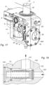
- This device 1 comprises a body 13 in which are formed bores forming pipes of the withdrawal circuit 2, of the filling 7, of the leakage circuit 10 and of the safety circuit 9, as well as receiving cavities for the various organs of the device 1.
- the storage connector 3 comprises a cylindrical connector 30 projecting from one side which is crossed by a main pipe 31 connected to the upstream end 21 of the withdrawal circuit 2, this connector 30 being intended to be connected to the storage container RE so that the gas flows in the main pipe 31.
- the shape of the connector 30 will depend on the connection interface of the storage container RE.
- the storage connector 3 also comprises a leak pipe 32 connected to the leak circuit 10 and emerging between two concentric seals 33, 34; these seals 33, 34 being positioned around the connector 30.
- a double sealing barrier is provided between the leak pipe 32 for optimum safety in the event of a leak at the level of the connector 30.
- the controlled isolation valve 4 comprises a valve 40 controlled by a motor member 41 between a closed position of the withdrawal circuit 2 and an open position of the withdrawal circuit, with the complementary action of a return member 42 which urges the valve 40 towards the closed position in the absence of actuation of the motor member 41.
- the valve 40 comprises a piston 43 movable under the action of the motor member 41, this piston 43 having an isolation valve 44 which rests on a seat 45.
- the motor member 41 controls the movement of the piston 43 in the direction of a detachment of the isolation valve 44 vis-à-vis the seat 45 for an opening of the valve 40 between its inlet 46 and its outlet 47.
- the return member 42 in particular of the helical spring type, exerts as for him a force on the piston 43 to urge it in the direction of a regluing of the isolation valve 44 on the seat 45 for a closure of the valve 40.
- the valve 40 incorporates a leak pipe 48 connected to the leak circuit 10 and arranged upstream of the isolation valve 44, to evacuate to the leak circuit 10 any leaks at the level of the bore receiving the valve 40 and also at the level of the movable piston 43.
- This leak pipe 48 is framed by seals 480, 481, 482 which guarantee a double sealing barrier in the management of leaks.
- the valve 40 incorporates another leak pipe 49 (visible on the figure 11 ) connected to the leakage circuit 10 and arranged downstream of the valve isolation 44, to evacuate to the leak circuit 10 any leaks at the bore receiving the valve 40 and also at the piston 43 mobile.
- This leak pipe 49 is framed by seals 490, 491 which guarantee a double sealing barrier in the management of leaks.
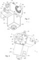
- the motor member 41 is mounted in a motor casing 410 fixed to the body 13 and an electrical outlet 411 is provided on the exterior of the motor casing 410.
- a knob 412 is also provided on the exterior of the casing 410, where this knob 412 makes it possible to deactivate and withdraw the motor member 41, so that only the return member 42 acts in the direction of closing the valve 40.
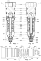
- the first regulator 5 is described below with reference to the figures 21 to 23 , where this first regulator 5 is mounted inside a bore whose bottom is in communication with the outlet of the valve 40.
- a leak pipe 17 (visible on the figure 10 ) formed in the body 13 is connected to the leakage circuit 10 and opens into the bore of the first regulator 5 between the two seals 512, again with a double sealing barrier.
- This first regulator 5 comprises a static upstream body 53 having an upper portion 54 extended by a lower portion 55, where the upper portion 54 faces the piston 52 so that the intermediate chamber 524 is delimited between the piston 52 and the upper portion 54 of the upstream body 53.
- the intermediate chamber 524 is connected to the leakage circuit 10 or to the safety circuit 9, via a discharge pipe 14 provided in the body 13 and visible on the figure 17 And 18 .
- the upper portion 54 is provided with an external thread 540 for fixing by screwing into the body 13, and more specifically fixing to the bottom of the corresponding bore, until this upper portion 54 is in abutment on a shoulder inside the bore via a seal 541.
- the upstream body 53 delimits with the bottom of the bore, under the internal shoulder, a high pressure chamber 56 at the inlet of the first regulator 5, this high pressure chamber 56 being connected to the outlet of the valve 40.
- the upper portion 54 has an internal through channel 542 having an upper end which opens into the intermediate chamber 524 and a lower end which opens into the high pressure chamber 56.
- the lower portion 55 has a lower dome 550 resting on the bottom of the bore for an EN inlet of the high pressure gas, where this lower dome 550 is provided with side holes 551 opening into the high pressure chamber 56.
- the lower dome 550 has an upper face facing the lower end of the internal channel 542, and a cavity is formed in this upper face to form a relaxation seat 552.
- the lower portion 55 comprises a cylindrical wall 553 which surrounds the upper face of the lower dome 550, where this cylindrical wall 553 is provided with side holes 554 opening into the high pressure chamber 56.
- the gas enters the interior of the lower dome 550 as shown schematically by the arrow EN on the figure 21 , then the gas leaves the high pressure chamber 56 through the side holes 551 and enters at the level of the expansion seat 552 through the side holes 554 as shown schematically by the arrow CH on the figure 21 .
- This path of the gas advantageously contributes to the desired gas expansion function.
- This first regulator 5 also comprises a first return member 58, in this case a helical spring, compressed between the piston 52 and the upstream body 53 and urging the piston 52 in the direction of the downstream body 51 (in other words in the direction of pressing piston 52 against downstream body 51).
- a first return member 58 in this case a helical spring, compressed between the piston 52 and the upstream body 53 and urging the piston 52 in the direction of the downstream body 51 (in other words in the direction of pressing piston 52 against downstream body 51).
- This first regulator 5 also comprises a second return member 59, in this case a helical spring, compressed between the piston 52 and a plate 573 integral with the valve stem 57.
- This second return member 59 extends inside the first return member 58, and the plate 573 can for example be formed by a circlip tightened around the valve stem valve 57.
- This second return member 59 urges the valve stem 57, relative to the piston 52, in the direction of a pressing of the relief valve 571 against the relief seat 521, in other words in the direction of the relief valve 571 to the upstream closed position.
- the following description relates to the operation of the first regulator 5.
- the relief valve 571 and the second return member 59 together form the relief valve 50 mentioned above with reference to the figure 1 .
- the second regulator 6 is described below with reference to the figures 24 to 28 , where this second regulator 6 is mounted inside a bore whose bottom is in communication with the outlet of the first regulator 5.
- a leak line 18 (visible on the figure 10 ) formed in the body 13 is connected to the leakage circuit 10 and opens into the bore of the second regulator 6 between the two seals 612, again with a double sealing barrier.
- This second regulator 6 comprises a static upstream body 63 having an upper portion 64 extended by a lower portion 65, where the upper portion 64 faces the piston 62 so that the intermediate chamber 624 is delimited between the piston 62 and the upper portion 64 of the upstream body 63.
- the intermediate chamber 624 is connected to the leakage circuit 10 or to the safety circuit 9, via a discharge pipe 15 arranged in the body 13 and visible on the figure 16 And 18 .
- the upper portion 64 is provided with an external thread 640 for fixing by screwing into the body 13, and more specifically fixing to the bottom of the corresponding bore, until this upper portion 64 is in abutment on a shoulder inside the bore via a seal 641.
- the upstream body 63 delimits with the bottom of the bore, under the internal shoulder, a high pressure chamber 66 at the inlet of the second regulator 6, this high pressure chamber 66 being connected to the outlet of the first regulator 5, in other words to the low pressure chamber 513 of this first regulator 5.
- the upper portion 64 has an internal through channel 642 having an upper end which opens into the intermediate chamber 624 and a lower end which opens into the high pressure chamber 66.
- the lower portion 65 has a lower dome 650 resting on the bottom of the bore for an EN inlet of the high pressure gas, where this lower dome 650 is provided with side holes 651 opening into the high pressure chamber 66.
- the lower dome 650 has an upper face facing the lower end of the internal channel 642, and a cavity is formed in this upper face to form a relaxation seat 652.
- the lower portion 65 comprises a cylindrical wall 653 which surrounds the upper face of the lower dome 650, where this wall cylindrical 653 is provided with side holes 654 opening into the high pressure chamber 66.
- the gas enters inside the lower dome 650, then the gas leaves the high pressure chamber 66 through the side holes 651 and enters at the level of the expansion seat 652 through the side holes 654.
- This path gas advantageously participates in the desired gas expansion function.
- This second regulator 6 also comprises a first return member 68, in this case a helical spring, compressed between the piston 62 and the upstream body 63 and urging the piston 62 in the direction of the downstream body 61 (In other words in the direction of pressing the piston 62 against the downstream body 61).
- a first return member 68 in this case a helical spring, compressed between the piston 62 and the upstream body 63 and urging the piston 62 in the direction of the downstream body 61 (In other words in the direction of pressing the piston 62 against the downstream body 61).
- This second regulator 6 also comprises a second return member 69, in this case a helical spring, compressed between the piston 62 and a plate 673 secured to the valve stem 67.
- This second return member 69 extends to the interior of the first return member 68, and the plate 673 can for example be formed of a circlip tightened around the valve stem 67.
- This second return member 69 urges the valve stem 67, relative to the piston 62, in the direction of a pressing of the relief valve 671 against the relief seat 621, in other words in the direction of the relief valve 671 towards the upstream closed position.
- This second regulator 6 is thus relatively close to the first regulator described previously, with a first difference which lies in a difference in the dimensions because the pressure upstream of the second regulator 6 corresponds to the pressure downstream of the first regulator 5, in other words to the pressure released by this first regulator 5.
- the function of the first regulator 5 is to release a high pressure, in particular of the order of 350 to 700 bars, in order to output a medium pressure, in particular of the order of 10 to 30 bars, and the second regulator 6 has the function of relaxing this medium pressure, in particular of the order of 10 to 30 bars, in order to deliver a low pressure at the outlet, in particular of the order of 0.5 to 5 bars.
- the piston 62 of the second regulator 6 has an upper face whose area is greater than that of the piston 52 of the first regulator 5.
- the return members 68, 69 also have different return coefficients from those of the return members 58, 59.
- a second difference is that the second regulator 6 includes a safety system 601, with manual reset, in the event of a pressure drop in the low pressure chamber 613 (equivalent to an overflow at the outlet of the second regulator 6) which would result in a leak downstream, and in particular a leak in the withdrawal unit.
- the low threshold pressure PSB can be established by considering a maximum value QM of gas flow at the outlet of the second regulator 6 which is considered as a high threshold not to be exceeded for the flow because reflecting a malfunction at the level of the withdrawal member may correspond to a leak. This maximum value QM is then to be compared with a difference between the nominal pressure at the outlet of the second regulator 6 (which corresponds to the pressure of use by the withdrawal member) and the low threshold pressure PSB.
- This obturator finger 602 is slidably mounted in an orifice 615 made through it in the downstream body 61, with the interposition of two O-ring seals 616; a leak pipe 617 connected to the leak circuit 10 is formed in the downstream body 61 by opening into the orifice 615 between the two seals 616.
- This safety system 601 comprises an adjustment screw 603 screwed into a thread provided in the orifice 615, above the obturator finger 602, this adjustment screw 603 being accessible from the outside to allow selective movement of the obturator finger 602 by screwing/unscrewing the adjustment screw 603 which comes into abutment on the obturator finger 602.
- This security system 601 comprises a stop screw 604 which is also screwed into a thread provided in the orifice 615, above the adjustment screw 603.
- This stop screw 604 is hollow, to allow access with a suitable tool to the adjustment screw 603, and this stop screw 604 forms a high stop stop for the adjustment screw 603; a lower stop abutment for the adjustment screw 603 being formed by an internal shoulder 605 in the orifice 615.
- the following description relates to the operation of the second regulator 6.
- FIG. 24 illustrates a starting configuration, which corresponds to a locked configuration prohibiting regulation for the second regulator 6, with the safety system 601 in closed mode.
- This starting configuration corresponds to a configuration at start-up (or start-up) of device 1, and also to a configuration after the safety system 601 has closed automatically following a drop in downstream pressure below the pressure low threshold.
- downstream pressure pressure in the low pressure chamber 613
- a low threshold pressure redirecting, as a reminder, an overflow at the outlet and therefore a leak downstream
- the piston 62 rises (under the effect of the first return member 68) until the obturator finger 602 comes into abutment on the open upper end of the valve stem 67, and the second regulator 6 returns to the starting configuration of the figure 24 .
- the relief valve 671, the relief seat 671 and the second return member 69 together form the relief valve 60 mentioned above with reference to the figure 1 .
- the filling connection 8 is described below with reference to the figures 8 and 9 .
- This filling connector 8 comprises a static hollow body 80 upstream forming a cover or plug accessible from the outside and provided with an external thread 800 for fixing by screwing into the body 13, this hollow body 80 having an internal thread 801 extended through a central hole 802.
- This filling connector 8 comprises a piston 81 screwed into the internal threading 801 of the upstream body 80 and internally presenting a filling pipe 82.
- the filling pipe 82 emerges at the end of the smooth portion 814, before the end portion 814, via peripheral holes 820.
- This smooth portion 814 also has at least one purge orifice 816 opening transversely into the filling pipe 82, at a distance from the peripheral holes 820.
- This filling connector 8 comprises a static downstream body 83 provided with an external thread 830 for fixing by screwing into the body 13, and more specifically fixing at the bottom of the corresponding bore, until this downstream body 83 either in abutment on an internal shoulder of the bore.
- This filling connector 8 comprises a purge body 84 inserted between the upstream body 80 and the downstream body 83 and having at least one purge pipe 841 connected to the leakage circuit 10 or to the safety circuit 9 via a purge pipe 16 formed in the body 13 and visible on the figure 13 .
- This purge pipe 841 opens out at the periphery of the smooth portion 814 of the piston 81, between two seals 817 mounted around this smooth portion 814 in the upstream body 80 and the downstream body 83 respectively.
- This filling connector 8 also comprises a return member 86, in particular of the coil spring type, which urges the isolation valve 85 towards the upstream closed position.
- the piston 81 is movable by screwing/unscrewing selectively between an open position (illustrated in the figure 8 ) and a closed position (shown in the figure 9 ).
- the piston 81 is movable by any mechanical action guaranteeing a translational movement of the piston between its open position and its closed position, where the piston 81 remains connected in a sealed manner in the upstream body 80.
- the piston 81 can be moved with a quarter-turn mechanism or other equivalent mechanism.
- the piston 81 is in its closed position and the gas source SO is connected to the socket 812, then the piston 81 is screwed to its open position and the gas source SO is opened to fill the storage container RE.
- the gas source SO is closed, the piston 81 is unscrewed towards its closed position so that an automatic depressurization of the filling pipe 82 takes place through the purge orifice 816 towards the circuit of leak 10 or the safety circuit 9, and finally the SO gas source is disconnected from the socket 812.
- the high pressure safety valve 93 comprises a valve 932 resting on a seat 933 open to the inlet, under the effect of a return member 934.
- the valve 932 opens under the effect of this high pressure and puts the inlet 930 and the outlet 931 in communication.
- This high pressure safety valve 93 thus has the function of evacuating the gas to the outside in the event of excessive pressure in the device 1.
- the high temperature safety valve 94 comprises a piston 942 provided with a rod 943 which cuts the communication between the inlet 940 and the outlet 941, and a base 944 resting on a thermally fuse pad 945, itself resting on a 947 sintered metal screen.
- a return member 946 rests on the base 944 to bias the piston 942 against the thermally fuse pad 945.
- the thermally fuse chip 945 is not melted and the rod 943 cuts the communication between the input 940 and the output 941, so that the high temperature safety valve 94 is closed.
- the thermally fusible pad 945 is melted and the rod 943 is urged by the return member 946 and/or by the pressure at the inlet 940, in the direction of an opening of the communication between the inlet 940 and the outlet 941, so that the high temperature safety valve 94 is open.
- the low pressure safety valve 12 comprises a valve 122 resting on a seat 123 open on the inlet 120, under the effect of a return member 124. If the pressure at the inlet 120 exceeds a threshold value greater than the maximum pressure provided in the withdrawal member (threshold value for example of the order of 2 to 5 bars), the valve 122 opens under the effect of this pressure and puts the inlet 120 in communication with the outlet 121.
- This low pressure safety valve 12 thus has the function of evacuating the gas to the outside in the event of excessive pressure in the withdrawal member.
- the device 1 can do without this low pressure safety valve 12 if the latter is redundant with a safety valve integrated into the withdrawal member.
- the low pressure safety valve 12 can still be present in the device 1.
Description
La présente invention se rapporte à un détendeur de gaz, ainsi qu'à un dispositif de remplissage et de soutirage de gaz muni d'un tel détendeur.The present invention relates to a gas regulator, as well as to a device for filling and withdrawing gas provided with such a regulator.
Classiquement, un dispositif de remplissage et de soutirage de gaz comprend un circuit de soutirage muni d'un raccord de stockage raccordé à un récipient de stockage d'un gaz sous pression et d'un raccord de soutirage raccordé à un organe de soutirage du gaz à pression réduite, et un circuit de remplissage muni d'un raccord de remplissage conformé pour un raccordement avec une source de gaz sous pression pour le remplissage du récipient de stockage.Conventionally, a gas filling and withdrawal device comprises a withdrawal circuit provided with a storage connector connected to a pressurized gas storage container and a withdrawal connector connected to a gas withdrawal member at reduced pressure, and a filling circuit provided with a shaped filling connector for connection with a pressurized gas source for filling the storage container.
L'invention trouve une application particulière, et non limitative, dans le remplissage et le soutirage d'hydrogène gazeux pour alimenter un organe de soutirage de type pile à combustible, en particulier au sein d'un véhicule.The invention finds a particular, and non-limiting, application in the filling and withdrawal of gaseous hydrogen to supply a fuel cell type withdrawal device, in particular within a vehicle.
Pour soutirer du gaz sous haute pression, classiquement entre 350 et 700 bars pour les réservoirs de stockage d'hydrogène gazeux, afin de le distribuer à basse pression, classiquement entre 1 et 5 bars, il est indispensable de recourir à un dispositif ou robinet de remplissage et de soutirage de gaz qui va avoir pour fonction de permettre un raccordement avec une source de pression dans le but de remplir lorsque nécessaire le récipient de stockage, et aussi de contrôler les opérations de soutirage de gaz parmi lesquelles figurent les opérations d'isolement, de sécurité et de détente du gaz.To extract gas under high pressure, typically between 350 and 700 bars for gaseous hydrogen storage tanks, in order to distribute it at low pressure, typically between 1 and 5 bars, it is essential to use a device or valve for gas filling and withdrawal which will have the function of allowing a connection with a source of pressure in order to fill the storage container when necessary, and also to control the gas withdrawal operations including the isolation operations , safety and gas release.
L'état de la technique peut être illustré par l'enseignement du document
Il est aussi connu du document
L'état de la technique peut également être illustré par les documents
L'invention propose un détendeur qui intègre une soupape de décharge configurée pour une décharge vers un circuit de fuite en cas de surpression en aval, c'est-à-dire en cas de dépassement de la pression aval au-delà d'une pression seuil prédéfinie. En effet, dans le domaine de la détente de gaz, une surpression aval est susceptible d'endommager le matériel, et en particulier les joints d'étanchéité avec pour conséquence des fuites.The invention proposes a pressure reducer which incorporates a relief valve configured for a relief towards a leak circuit in the event of overpressure downstream, that is to say in the event of the downstream pressure exceeding a pressure predefined threshold. Indeed, in the field of gas expansion, a downstream overpressure is likely to damage the equipment, and in particular the seals with the consequence of leaks.
De telles fuites peuvent être particulièrement critiques dans le cadre des dispositifs de remplissage et de soutirage d'hydrogène gazeux, en particulier au sein d'un véhicule transportant des personnes.Such leaks can be particularly critical in the context of devices for filling and withdrawing gaseous hydrogen, in particular within a vehicle transporting people.
La présente invention a notamment pour but de proposer un détendeur qui intègre une telle soupape de décharge en cas de surpression c'est-à-dire que le détendeur possède sa propre soupape de décharge, ce qui contribue à une sécurité et une compacité accrues.The object of the present invention is in particular to propose a regulator which incorporates such a relief valve in the event of overpressure, that is to say that the regulator has its own relief valve, which contributes to increased safety and compactness.
Un autre but de l'invention est de proposer un détendeur fiable pour détendre un gaz entre une pression amont de l'ordre de 350 à 700 bars et une pression aval de l'ordre de 10 à 30 bars, et aussi pour détendre un gaz entre une pression amont de l'ordre de 10 à 30 bars et une pression aval de l'ordre de 0,5 à 5 bars.Another object of the invention is to provide a reliable regulator for expanding a gas between an upstream pressure of the order of 350 to 700 bars and a downstream pressure of the order of 10 to 30 bars, and also for expanding a gas between an upstream pressure of the order of 10 to 30 bars and a downstream pressure of the order of 0.5 to 5 bars.
Un autre but de l'invention est de proposer un détendeur adapté pour un dispositif de remplissage et de soutirage à la fois d'encombrement et de poids réduits.Another object of the invention is to provide a pressure reducer suitable for a filling and withdrawal device that is both bulky and light in weight.
A cet effet, elle propose un détendeur comprenant :
- un corps aval statique délimitant une chambre basse pression en sortie du détendeur ;
- un corps amont délimitant une chambre haute pression en entrée du détendeur et portant un siège de détente disposé en regard d'un canal interne ménagée dans une portion supérieure du corps amont ;
- un piston mobile formant une pièce de régulation sur laquelle appuie d'un côté le gaz de la chambre basse pression et de l'autre côté un premier organe de rappel ;
- un clapet de régulation coopérant avec la pièce de régulation et mobile relativement au siège de détente entre une position amont de fermeture de la communication entre la chambre basse pression et la chambre haute pression et une position aval d'ouverture de la communication entre la chambre basse pression et la chambre haute pression ;
- (i) le piston présente un canal interne traversant ayant deux extrémités opposées :
- une extrémité supérieure ouverte, du côté du corps aval, faisant face à la chambre basse pression et formant un siège de décharge, et
- une extrémité inférieure qui débouche sur une chambre intermédiaire intercalée entre le corps amont et le corps aval, où ladite chambre intermédiaire est raccordée à un circuit de fuite ;
- (ii) le détendeur comprend en outre une tige de soupape tubulaire munie d'un canal interne, la tige de soupape traversant à la fois le canal interne du piston et le canal interne de la portion supérieure du corps amont, de sorte que cette tige de soupape présente :
- une extrémité supérieure évasée formant un clapet de décharge propre à venir en appui sur le siège de décharge prévu à l'extrémité supérieure du canal interne du piston ; et
- une extrémité inférieure formant le clapet de régulation propre à venir en appui sur le siège de détente ;
- (iii) le premier organe de rappel est comprimé entre le piston et le corps amont en sollicitant le piston en direction du corps aval, et un second organe de rappel est comprimé entre le piston et un plateau solidaire de la tige de soupape sollicitant la tige de soupape, relativement au piston, dans le sens d'un plaquage du clapet de décharge contre le siège de décharge.
- a static downstream body delimiting a low-pressure chamber at the outlet of the regulator;
- an upstream body delimiting a high-pressure chamber at the inlet of the regulator and carrying an expansion seat arranged opposite an internal channel formed in an upper portion of the upstream body;
- a movable piston forming a regulating part on which the gas from the low-pressure chamber presses on one side and on the other side a first return member;
- a regulating valve cooperating with the regulating part and movable relative to the expansion seat between an upstream position of closure of the communication between the low pressure chamber and the high pressure chamber and a downstream position for opening the communication between the low pressure chamber and the high pressure chamber;
- (i) the piston has a through internal channel having two opposite ends:
- an open upper end, on the side of the downstream body, facing the low pressure chamber and forming a relief seat, and
- a lower end which opens into an intermediate chamber interposed between the upstream body and the downstream body, where said intermediate chamber is connected to a leakage circuit;
- (ii) the regulator further comprises a tubular valve stem provided with an internal channel, the valve stem passing through both the internal channel of the piston and the internal channel of the upper portion of the upstream body, so that this rod of valve present:
- a flared upper end forming a relief valve capable of coming to rest on the relief seat provided at the upper end of the internal channel of the piston; And
- a lower end forming the own regulating valve to come to rest on the expansion seat;
- (iii) the first return member is compressed between the piston and the upstream body by biasing the piston in the direction of the downstream body, and a second return member is compressed between the piston and a plate integral with the valve stem biasing the stem valve, relative to the piston, in the direction of pressing the relief valve against the relief seat.
Ainsi, ce détendeur intègre une soupape de décharge configurée pour une décharge vers un circuit de fuite en cas de surpression en aval, où cette soupape de décharge comprend le clapet de décharge formé au niveau de la tige de soupape, le siège de décharge formé au niveau du piston, et le second organe de rappel.Thus, this regulator incorporates a relief valve configured for relief to a leak circuit in the event of overpressure downstream, where this relief valve comprises the relief valve formed at the valve stem, the relief seat formed at the level of the piston, and the second return member.
En effet, en cas de surpression dans la chambre basse pression, c'est-à-dire dans le cas où la pression aval dépasse une pression seuil prédéfinie (qui dépend des surfaces d'appui du gaz et des coefficients de rappel des organes de rappel) :
- la surpression dans la chambre basse pression agit sur le piston dans le sens d'un décollement vis-à-vis du corps aval suffisant pour que le clapet de régulation soit en position amont de fermeture, sous l'effet du second organe de rappel qui pousse la tige de soupape ;
- la tige de soupape étant en butée sur le siège de détente et le piston étant suffisamment écarté du corps aval, le clapet de décharge décolle du siège de décharge et passe ainsi en position aval d'ouverture, autorisant la communication entre la chambre basse pression et la conduite de décharge raccordée au circuit de fuite, et ainsi la décharge s'effectue dans le circuit de fuite et la pression aval est relâchée.
- the overpressure in the low pressure chamber acts on the piston in the direction of a separation vis-à-vis the downstream body sufficient for the valve to regulation either in the upstream closed position, under the effect of the second return member which pushes the valve stem;
- the valve stem being in abutment on the expansion seat and the piston being sufficiently spaced from the downstream body, the relief valve takes off from the relief seat and thus passes into the downstream open position, allowing communication between the low pressure chamber and the discharge line connected to the leakage circuit, and thus the discharge takes place in the leakage circuit and the downstream pressure is released.
Selon une caractéristique, le second organe de rappel s'étend à l'intérieur du premier organe de rappel.According to one characteristic, the second return member extends inside the first return member.
Selon une variante, le premier organe de rappel et le second organe de rappel sont des ressorts hélicoïdaux.According to a variant, the first return member and the second return member are helical springs.
Selon une autre caractéristique, le plateau est formé d'un circlips serré autour de la tige de soupape. En variante, ce plateau est soudé ou serti sur la tige de soupape, ou bien ce plateau vient de matière avec la tige de soupape.According to another characteristic, the plate is formed by a circlip tightened around the valve stem. As a variant, this plate is welded or crimped onto the valve stem, or else this plate is integral with the valve stem.
Dans une réalisation particulière, la portion supérieure du corps amont est munie d'un filetage externe pour une fixation par vissage dans un alésage.In a particular embodiment, the upper portion of the upstream body is provided with an external thread for fastening by screwing into a bore.
Dans un mode de réalisation particulier, le corps amont présente la portion supérieure prolongée par une portion inférieure, où la portion supérieure fait face au piston, et ladite portion inférieure présente une coupole inférieure en appui sur le fond d'un alésage pour une entrée de gaz, où cette coupole inférieure est munie de trous latéraux débouchant dans la chambre haute pression.In a particular embodiment, the upstream body has the upper portion extended by a lower portion, where the upper portion faces the piston, and said lower portion has a lower dome resting on the bottom of a bore for an inlet of gas, where this lower dome is provided with side holes opening into the high pressure chamber.
Avantageusement, la coupole inférieure présente une face supérieure en regard de l'extrémité inférieure du canal interne de la portion supérieure du corps amont, et une cavité est formée dans cette face supérieure pour former le siège de détente.Advantageously, the lower cupola has an upper face facing the lower end of the internal channel of the upper portion of the upstream body, and a cavity is formed in this upper face to form the expansion seat.
Selon une possibilité de l'invention, la portion inférieure du corps amont comprend une paroi cylindrique qui entoure la face supérieure de la coupole inférieure, où cette paroi cylindrique est munie de trous latéraux débouchant dans la chambre haute pression.According to one possibility of the invention, the lower portion of the upstream body comprises a cylindrical wall which surrounds the upper face of the lower dome, where this cylindrical wall is provided with side holes opening into the high pressure chamber.
Selon une autre possibilité de l'invention, le corps aval forme un couvercle ou bouchon accessible de l'extérieur d'un corps.According to another possibility of the invention, the downstream body forms a cover or stopper accessible from the outside of a body.
Avantageusement, le corps aval présente en périphérie extérieure deux joints d'étanchéité toriques à l'intérieur d'un alésage, et une conduite de fuite raccordée au circuit de fuite débouche dans l'alésage entre les deux joints d'étanchéité.Advantageously, the downstream body has two O-ring seals on the outer periphery inside a bore, and a leak pipe connected to the leak circuit opens into the bore between the two seals.
Conformément à une autre caractéristique de l'invention, le corps aval est fixé par vissage à l'intérieur d'un alésage.According to another characteristic of the invention, the downstream body is fixed by screwing inside a bore.
Dans un mode de réalisation avantageux, le détendeur comprend un système de sécurité avec réarmement manuel conformé pour fermer automatiquement la communication entre la chambre basse pression et la chambre haute pression lorsque la pression aval dans la chambre basse pression passe en-dessous d'une pression seuil basse prédéfinie correspondant à une augmentation du débit de gaz en sortie du détendeur, notamment associée à une fuite en aval (et en particulier à une fuite dans un organe de soutirage placé en aval du détendeur).In an advantageous embodiment, the regulator comprises a safety system with manual reset configured to automatically close the communication between the low pressure chamber and the high pressure chamber when the downstream pressure in the low pressure chamber drops below a pressure predefined low threshold corresponding to an increase in the gas flow at the outlet of the regulator, in particular associated with a leak downstream (and in particular with a leak in a withdrawal device placed downstream of the regulator).
Un tel système de sécurité permet :
- une fermeture de la communication entre la chambre basse pression et la chambre haute pression dans le cas où la pression aval (pression dans la chambre basse pression) passe en-dessous d'une pression seuil basse (ou valeur de consigne) ;
- interdire une remise en fonctionnement du détendeur tant que le défaut de chute de pression (qui traduit notamment une fuite dans l'organe de soutirage) n'est pas résolu ;
- permettre une remise en fonctionnement du détendeur uniquement par un réarmement manuel, une fois résolu le défaut de chute de pression (ou de fuite dans l'organe de soutirage).
- a closure of the communication between the low-pressure chamber and the high-pressure chamber in the event that the downstream pressure (pressure in the low-pressure chamber) falls below a low threshold pressure (or set point value);
- prohibit restarting the pressure reducer until the pressure drop fault (which in particular reflects a leak in the tapping device) is not resolved;
- allow the regulator to be put back into operation only by manual resetting, once the pressure drop fault (or leak in the withdrawal device) has been resolved.
Cette pression seuil basse peut être établie en considérant une valeur maximale de débit du gaz en sortie du détendeur qui est considérée comme un seuil haut à ne pas dépasser pour le débit car traduisant un dysfonctionnement au niveau de l'organe de soutirage pouvant correspondre à une fuite.This low threshold pressure can be established by considering a maximum value of gas flow at the outlet of the regulator which is considered as a high threshold not to be exceeded for the flow because reflecting a malfunction at the level of the withdrawal device which may correspond to a leak.
Selon une caractéristique, le système de sécurité comprend un doigt obturateur monté mobile dans le corps aval en regard de l'extrémité supérieure ouverte de la tige de soupape, où ce doigt obturateur est déplaçable sélectivement entre :
- une position abaissée dans laquelle le doigt obturateur est rapproché de l'extrémité supérieure ouverte de la tige de soupape ; et
- une position relevée dans laquelle le doigt obturateur est éloigné de l'extrémité supérieure ouverte de la tige de soupape.
- a lowered position in which the shutter finger is brought closer to the open upper end of the valve stem; And
- a raised position in which the shutter finger is moved away from the open upper end of the valve stem.
Selon une autre caractéristique, le doigt obturateur est monté coulissant dans un orifice ménagé traversant dans le corps aval.According to another feature, the shutter finger is mounted to slide in an orifice made through it in the downstream body.
Avantageusement, le doigt obturateur présente en périphérie extérieure deux joints d'étanchéité toriques à l'intérieur de l'orifice du corps aval, une conduite de fuite raccordée au circuit de fuite est ménagée dans le corps aval en débouchant dans ledit orifice entre les deux joints d'étanchéité.Advantageously, the obturator finger has two O-ring seals on the outer periphery inside the orifice of the downstream body, a leak pipe connected to the leak circuit is formed in the downstream body by opening into said orifice between the two seals.
Selon une possibilité, le système de sécurité comprend une vis de réglage vissée dans un filetage prévu dans l'orifice du corps aval pour permettre de déplacer sélectivement le doigt obturateur en vissant/dévissant la vis de réglage qui vient en butée sur le doigt obturateur.According to one possibility, the safety system comprises an adjustment screw screwed into a thread provided in the orifice of the downstream body to allow the shutter finger to be moved selectively by screwing/unscrewing the adjustment screw which comes into abutment on the shutter finger.
Selon une autre possibilité, le système de sécurité comprend une vis d'arrêt creuse vissée dans un filetage prévu dans l'orifice du corps aval pour former une butée haute d'arrêt pour la vis de réglage, et une butée basse d'arrêt pour la vis de réglage est formée par un épaulement interne dans ledit orifice.According to another possibility, the safety system comprises a hollow stop screw screwed into a thread provided in the orifice of the downstream body to form an upper stop stop for the adjustment screw, and a lower stop stop for the adjustment screw is formed by an internal shoulder in said orifice.
L'invention se rapporte également à un dispositif de remplissage et de soutirage de gaz, comprenant :
- un circuit de soutirage comprenant une extrémité amont munie d'un raccord de stockage conformé pour un raccordement avec un récipient de stockage d'un gaz sous pression, et une extrémité aval munie d'un raccord de soutirage conformé pour un raccordement avec un organe de soutirage du gaz à pression réduite, où ledit circuit de soutirage comprend au moins une vanne d'isolation pilotée et au moins un détendeur conforme à l'invention ;
- un circuit de remplissage comprenant une extrémité amont munie d'un raccord de remplissage conformé pour un raccordement avec une source de gaz sous pression pour le remplissage du récipient de stockage, et une extrémité aval raccordée à l'extrémité amont du circuit de soutirage.
- a draw-off circuit comprising an upstream end provided with a storage connection shaped for connection with a storage container for a pressurized gas, and a downstream end provided with a draw-off connection shaped for connection with a withdrawing gas at reduced pressure, where said withdrawing circuit comprises at least one controlled isolation valve and at least one regulator according to the invention;
- a filling circuit comprising an upstream end provided with a shaped filling connector for connection with a pressurized gas source for filling the storage container, and a downstream end connected to the upstream end of the withdrawal circuit.
Avantageusement, le circuit de soutirage comprend un premier détendeur et un second détendeur en série, où chaque détendeur est conforme à l'invention.Advantageously, the withdrawal circuit comprises a first regulator and a second regulator in series, where each regulator is in accordance with the invention.
L'emploi de deux détendeurs en série permet de fiabiliser la régulation de la pression entre le récipient de stockage à haute pression et l'organe de soutirage fonctionnant à basse pression.The use of two regulators in series makes it possible to make reliable the regulation of the pressure between the high-pressure storage container and the withdrawal member operating at low pressure.
Selon une réalisation particulière, seul le second détendeur intègre un système de sécurité avec réarmement manuel tel que décrit ci-dessus.According to a particular embodiment, only the second regulator incorporates a safety system with manual reset as described above.
L'invention se rapporte également à une utilisation d'un dispositif de remplissage et de soutirage selon l'invention, dans lequel le raccord de stockage est raccordé à un récipient de stockage d'hydrogène gazeux sous pression et le raccord de soutirage est raccordé à un organe de soutirage du type pile à combustible.The invention also relates to a use of a filling and withdrawal device according to the invention, in which the storage connection is connected to a pressurized hydrogen gas storage container and the withdrawal connection is connected to a fuel cell type withdrawal member.
D'autres caractéristiques et avantages de la présente invention apparaîtront à la lecture de la description détaillée ci-après, d'un exemple de mise en oeuvre non limitatif, faite en référence aux figures annexées dans lesquelles :
- la
figure 1 est une vue schématique illustrant la structure d'un exemple possible de réalisation d'un dispositif de remplissage et de soutirage selon l'invention ; - les
figures 2 à 5 sont des vues schématiques en perspective et selon différents angles de vue d'un dispositif de remplissage et de soutirage selon l'invention ; - les
figures 6 et 7 sont des vues schématiques de côté du dispositif desfigures 2 à 5 ; - les
figures 8 sont des vues schématiques en coupe d'un raccord de remplissage du dispositif deset 9figures 2 à 7 , dans une position d'ouverture (figure 8 ) et dans une position de fermeture (figure 9 ) ; - la
figure 10 est une vue schématique en coupe du dispositif desfigures 2 à 7 selon le plan de coupe X-X de lafigure 7 ; - la
figure 11 est une vue schématique en coupe du dispositif desfigures 2 à 7 selon le plan de coupe XI-XI de lafigure 6 ; - la
figure 12 est une vue schématique en coupe du dispositif desfigures 2 à 7 selon le plan de coupe XII-XII de lafigure 7 ; - la
figure 13 est une vue schématique en coupe du dispositif desfigures 2 à 7 selon le plan de coupe XIII-XIII de lafigure 6 ; - la
figure 14 est une vue schématique en perspective et partiellement transparente du dispositif desfigures 2 à 7 ; - les
figures 15 à 18 sont des vues schématiques en perspective du dispositif desfigures 2 à 7 coupé selon différents plans de coupe ; - la
figure 19 est une vue schématique en coupe d'une soupape de sécurité basse pression du dispositif desfigures 2 à 7 , illustrée dans un corps d'essai (et pas dans le corps du dispositif) pour des raisons de clarté ; - la
figure 20 est une vue schématique en coupe d'une vanne d'isolation pilotée du dispositif desfigures 2 à 7 , illustrée dans un corps d'essai, sans représentation de la motorisation ; - les
figures 21 et 22 sont des vues schématiques en coupe d'un premier détendeur conforme à l'invention, ou détendeur haute pression, pour le dispositif desfigures 2 à 7 , dans une configuration ouverte de repos ou de régulation (figure 21 ) et dans une configuration fermée de décharge en cas de surpression dans la chambre basse pression (figure 22 ) ; - la
figure 23 est une vue schématique de côté du premier détendeur desfigures 21 ;et 22 - les
figures 24 à 27 sont des vues schématiques en coupe d'un second détendeur conforme à l'invention, ou détendeur basse pression, pour le dispositif desfigures 2 à 7 , dans une configuration verrouillée interdisant la régulation (figure 24 ), dans une configuration déverrouillée en première phase de réarmement après remontée du doigt obturateur (figure 25 ), dans une configuration déverrouillée en seconde phase d'armement (figure 26 ), dans une configuration ouverte de régulation (figure 27 ) ; - la
figure 28 est une vue schématique de côté du second détendeur desfigures 24 et27 ; - la
figure 29 est une vue zoomée sur une partie de lafigure 13 illustrant schématiquement et en coupe une soupape de sécurité haute pression du dispositif desfigures 2 à 7 ; - la
figure 30 est une vue schématique en coupe de la soupape de sécurité haute pression de lafigure 29 , illustrée dans un corps d'essai ; - les
figures 31 et 32 sont des vues schématiques en coupe d'une soupape de sécurité haute température du dispositif desfigures 2 à 7 , illustrée dans un corps d'essai, en configuration ouverte au-dessus d'une température seuil (figure 31 ) et en configuration fermée en-dessous de la température seuil (figure 32 ).
- there
figure 1 is a schematic view illustrating the structure of a possible embodiment of a filling and withdrawal device according to the invention; - THE
figures 2 to 5 are schematic views in perspective and from different angles of view of a filling and withdrawal device according to the invention; - THE
figure 6 And7 are schematic side views of the device of thefigures 2 to 5 ; - THE
figures 8 and 9 are schematic cross-sectional views of a filling connection of the device of thefigures 2 to 7 , in an open position (figure 8 ) and in a closed position (figure 9 ); - there
figure 10 is a schematic sectional view of the device of thefigures 2 to 7 according to section plan XX of thefigure 7 ; - there
figure 11 is a schematic sectional view of the device of thefigures 2 to 7 according to section plan XI-XI of thefigure 6 ; - there
figure 12 is a schematic sectional view of the device of thefigures 2 to 7 according to section plan XII-XII of thefigure 7 ; - there
figure 13 is a schematic sectional view of the device of thefigures 2 to 7 according to section plan XIII-XIII of thefigure 6 ; - there
figure 14 is a schematic view in perspective and partially transparent of the device of thefigures 2 to 7 ; - THE
figures 15 to 18 are schematic perspective views of the device of thefigures 2 to 7 cut according to different cutting planes; - there
figure 19 is a schematic sectional view of a low pressure safety valve of the device of thefigures 2 to 7 , illustrated in a test body (not in device body) for clarity; - there
figure 20 is a schematic sectional view of a pilot-operated isolation valve of the device of thefigures 2 to 7 , illustrated in a test body, without representation of the engine; - THE
figures 21 and 22 are schematic sectional views of a first regulator according to the invention, or high pressure regulator, for the device offigures 2 to 7 , in an open resting or regulating configuration (figure 21 ) and in a closed relief configuration in the event of overpressure in the low pressure chamber (figure 22 ); - there
figure 23 is a schematic side view of the first regulator of thefigures 21 and 22 ; - THE
figures 24 to 27 are schematic sectional views of a second regulator according to the invention, or low pressure regulator, for the device of thefigures 2 to 7 , in a locked configuration prohibiting regulation (figure 24 ), in an unlocked configuration in the first resetting phase after raising the obturator finger (figure 25 ), in an unlocked configuration in the second phase of arming (figure 26 ), in an open regulation configuration (figure 27 ); - there
figure 28 is a schematic side view of the second regulator of thefigure 24 And27 ; - there
figure 29 is a zoomed view of part of thefigure 13 illustrating schematically and in section a high pressure safety valve of the device of thefigures 2 to 7 ; - there
figure 30 is a schematic sectional view of the high pressure safety valve of thefigure 29 , shown in a trial body; - THE
figures 31 and 32 are schematic sectional views of a high temperature safety valve of the device of thefigures 2 to 7 , illustrated in a test body, in an open configuration above a threshold temperature (figure 31 ) and in closed configuration below the threshold temperature (figure 32 ).
Un dispositif 1 de remplissage et de soutirage de gaz selon l'invention comprend un circuit de soutirage 2 comprenant :
- une extrémité amont 21 munie d'un raccord de stockage 3 conformé pour un raccordement avec un récipient de stockage RE d'un gaz sous pression, et
- une extrémité aval 22 munie d'un raccord de soutirage 25 conformé pour un raccordement avec un organe de soutirage (non illustré) du gaz à pression réduite.
- an
upstream end 21 provided with astorage connector 3 shaped for connection with a storage container RE for a pressurized gas, and - a
downstream end 22 provided with a draw-off connector 25 shaped for connection with a draw-off device (not shown) for gas at reduced pressure.
Entre ces deux extrémités 21, 22, le circuit de soutirage 2 comprend successivement, en partant de l'extrémité amont 21, une vanne d'isolation pilotée 4, un premier détendeur 5 et un second détendeur 6. Le circuit de soutirage 2 comprend également, en amont de la vanne d'isolation pilotée 4, une sonde de température 23 et une sonde de pression 24.Between these two ends 21, 22, the
Le premier détendeur 5 est associé à, ou intègre, une soupape de décharge 50 disposée en aval entre le circuit de soutirage 2 et un circuit de fuite 10, où cette soupape de décharge 50 est configurée pour une décharge vers le circuit de fuite 10 en cas de surpression en aval, c'est-à-dire en cas de dépassement de la pression aval au-delà d'une première pression seuil prédéfinie (appelée aussi valeur de réglage ou valeur de tarage).The
Autrement dit, si la pression aval dépasse cette première pression seuil, un clapet de décharge de la soupape de décharge 50 est soulevé en opposition à la force d'un organe de rappel, de sorte que la soupape de décharge 50 s'ouvre afin que la pression aval diminue dans le circuit de fuite 10 (côté sortie). La soupape de décharge 50 se referme dès que la pression aval devient inférieure à la première pression seuil.In other words, if the downstream pressure exceeds this first threshold pressure, a relief valve of the
Le second détendeur 6 est associé à, ou intègre, une soupape de décharge 60 disposée en aval entre le circuit de soutirage 2 et le circuit de fuite 10, où cette soupape de décharge 60 est configurée pour une décharge vers le circuit de fuite 10 en cas de surpression en aval, c'est-à-dire en cas de dépassement de la pression aval au-delà d'une seconde pression seuil prédéfinie (appelée aussi valeur de réglage ou valeur de tarage).The
Autrement dit, si la pression aval dépasse cette seconde pression seuil, un clapet de décharge de la soupape de décharge 60 est soulevé en opposition à la force d'un organe de rappel, de sorte que la soupape de décharge 60 s'ouvre afin que la pression aval diminue dans le circuit de fuite 10 (côté sortie). La soupape de décharge 60 se referme dès que la pression aval devient inférieure à la seconde pression seuil.In other words, if the downstream pressure exceeds this second threshold pressure, a relief valve of the
Ce second détendeur 6 est suivi d'un limiteur de débit 600 avec un système de sécurité 601 avec réarmement manuel pour fermer le circuit de soutirage 2 en cas de baisse de la pression aval.This
Le dispositif 1 comprend également un circuit de remplissage 7 comprenant une extrémité amont 71 munie d'un raccord de remplissage 8 conformé pour un raccordement avec une source de gaz SO sous pression pour le remplissage du récipient de stockage RE, et une extrémité aval 72 raccordée à l'extrémité amont 21 du circuit de soutirage 2.The
Le dispositif 1 comprend un circuit de sécurité 9 ayant :
- une extrémité amont 91 raccordée à l'extrémité amont 21 du circuit de soutirage 2 ; et
- une extrémité amont 92 reliée à l'extérieur EXT, cette extrémité amont 92 formant un point de collecte sur l'extérieur.
- an
upstream end 91 connected to theupstream end 21 of thewithdrawal circuit 2; And - an
upstream end 92 connected to the outside EXT, thisupstream end 92 forming a collection point on the outside.
Ce circuit de sécurité 9 comprend, en parallèle, une soupape de sécurité haute pression 93, une soupape de sécurité haute température 94 et un robinet de purge 95 avec limiteur de débit. Le robinet de purge 95 a pour fonction principale de permettre une vidange contrôlée du récipient de stockage RE.This
Le dispositif 1 comprend le circuit de fuite 10 ayant :
- une sortie reliée à l'extérieur EXT, et plus spécifiquement reliée à l'extrémité amont 92 du circuit de sécurité 9, et
- des entrées raccordées à différents organes du dispositif 1, comme décrit ultérieurement, et notamment aux soupapes de sécurité 50, 60.
- an output connected to the outside EXT, and more specifically connected to the
upstream end 92 of thesafety circuit 9, and - inlets connected to various members of the
device 1, as described later, and in particular to thesafety valves
Ce circuit de fuite 10 comprend un clapet anti-retour 11 et une soupape de sécurité basse pression 12 ayant :
- une entrée raccordée à l'extrémité aval 22 du circuit de soutirage 2, en aval du
second détendeur 6 et aussi du limiteur de débit 600 ; et - une sortie d'échappement raccordée en amont du clapet anti-retour 11.
- an inlet connected to the
downstream end 22 of thewithdrawal circuit 2, downstream of thesecond regulator 6 and also of theflow limiter 600; And - an exhaust outlet connected upstream of the
non-return valve 11.
Dans le dispositif 1 décrit, le circuit de sécurité 9 et le circuit de fuite 10 sont en communication, et forment ensemble un seul et même circuit relié à l'extérieur EXT.In the
La suite de la description porte sur un exemple de réalisation de ce dispositif 1, dans une version compacte, légère, fiable et sécurisée.The rest of the description relates to an embodiment of this
Ce dispositif 1 comprend un corps 13 dans lequel sont ménagés des alésages formant des canalisations du circuit de soutirage 2, du circuit de remplissage 7, du circuit de fuite 10 et du circuit de sécurité 9, ainsi que des cavités de réception pour les différents organes du dispositif 1.This
Le raccord de stockage 3 comprend un connecteur 30 cylindrique en saillie d'une face qui est traversé par une conduite principale 31 raccordée à l'extrémité amont 21 du circuit de soutirage 2, ce connecteur 30 étant prévu pour être connecté sur le récipient de stockage RE de sorte que le gaz circule dans la conduite principale 31. Bien entendu, la forme du connecteur 30 va dépendre de l'interface de connexion du récipient de stockage RE.The
Le raccord de stockage 3 comprend également une conduite de fuite 32 raccordée au circuit de fuite 10 et débouchant entre deux joints d'étanchéité 33, 34 concentriques ; ces joints d'étanchéité 33, 34 étant positionnés autour du connecteur 30. Ainsi, une double barrière d'étanchéité est prévue entre la conduite de fuite 32 pour une sécurité optimale en cas de fuite au niveau du connecteur 30.The
La vanne d'isolation pilotée 4 comprend une vanne 40 commandée par un organe moteur 41 entre une position de fermeture du circuit de soutirage 2 et une position d'ouverture du circuit de soutirage, avec l'action complémentaire d'un organe de rappel 42 qui sollicite la vanne 40 vers la position de fermeture en l'absence d'actionnement de l'organe moteur 41.The controlled
En référence à la
La vanne 40 intègre une conduite de fuite 48 raccordée au circuit de fuite 10 et disposée en amont du clapet d'isolement 44, pour évacuer vers le circuit de fuite 10 d'éventuelles fuites au niveau de l'alésage réceptionnant la vanne 40 et également au niveau du piston 43 mobile. Cette conduite de fuite 48 est encadrée par des joints d'étanchéité 480, 481, 482 qui garantissent une double barrière d'étanchéité dans la gestion des fuites.The
La vanne 40 intègre une autre conduite de fuite 49 (visible sur la
L'organe moteur 41 est monté dans un carter moteur 410 fixé sur le corps 13 et une prise électrique 411 est prévue sur l'extérieur du carter moteur 410. Une molette 412 est également prévue sur l'extérieur du carter 410, où cette molette 412 permet de désactiver et de retirer l'organe moteur 41, de sorte que seul l'organe de rappel 42 agit dans le sens de la fermeture de la vanne 40.The
Le premier détendeur 5 est décrit ci-après en référence aux
Ce premier détendeur 5 comprend un corps aval 51 statique formant un couvercle ou bouchon accessible de l'extérieur et muni d'un filetage externe 510 pour une fixation par vissage dans le corps 13, ce corps aval 51 présentant :
- sur une face supérieure, un trou supérieur 511 borgne pour un outil de vissage/dévissage,
- en périphérie extérieure, deux joints d'étanchéité 512 toriques en-dessous du filetage externe 510, et
- sur une face inférieure opposée à la face supérieure, une cavité formant une chambre basse pression 513 en sortie du
premier détendeur 5, cette chambre basse pression 513 étant reliée à l'entrée dusecond détendeur 6.
- on an upper face, an upper
blind hole 511 for a screwing/unscrewing tool, - on the outer periphery, two O-
ring seals 512 below theexternal thread 510, and - on a lower face opposite the upper face, a cavity forming a
low pressure chamber 513 at the outlet of thefirst regulator 5, thislow pressure chamber 513 being connected to the inlet of thesecond regulator 6.
Une conduite de fuite 17 (visible sur la
Ce premier détendeur 5 comprend une pièce de régulation formée d'un piston 52 mobile conformé pour venir en appui sur la face inférieure du corps aval 51, ce piston 52 étant muni en périphérie extérieure d'un joint d'étanchéité 522 torique, et présentant un canal interne 520 traversant ayant :
- une extrémité supérieure, du côté du corps
aval 51, faisant face à la chambre basse pression 513 et formant un siège de décharge 521, et - une extrémité inférieure 523 opposée qui débouche sur une chambre intermédiaire 524.
- an upper end, on the side of the
downstream body 51, facing thelow pressure chamber 513 and forming arelief seat 521, and - an opposite
lower end 523 which opens into anintermediate chamber 524.
Ce premier détendeur 5 comprend un corps amont 53 statique présentant une portion supérieure 54 prolongée par une portion inférieure 55, où la portion supérieure 54 fait face au piston 52 de sorte que la chambre intermédiaire 524 est délimitée entre le piston 52 et la portion supérieure 54 du corps amont 53. La chambre intermédiaire 524 est reliée au circuit de fuite 10 ou au circuit de sécurité 9, via une conduite de décharge 14 ménagée dans le corps 13 et visible sur les
La portion supérieure 54 est munie d'un filetage externe 540 pour une fixation par vissage dans le corps 13, et plus spécifiquement une fixation au fond de l'alésage correspondant, jusqu'à ce que cette portion supérieure 54 soit en butée sur un épaulement interne de l'alésage via un joint d'étanchéité 541.The
Le corps amont 53 délimite avec le fond de l'alésage, sous l'épaulement interne, une chambre haute pression 56 en entrée du premier détendeur 5, cette chambre haute pression 56 étant reliée à la sortie de la vanne 40.The
La portion supérieure 54 présente un canal interne 542 traversant ayant une extrémité supérieure qui débouche sur la chambre intermédiaire 524 et une extrémité inférieure qui débouche sur la chambre haute pression 56.The
La portion inférieure 55 présente une coupole inférieure 550 en appui sur le fond de l'alésage pour une entrée EN du gaz sous haute pression, où cette coupole inférieure 550 est muni de trous latéraux 551 débouchant dans la chambre haute pression 56.The
La coupole inférieure 550 présente une face supérieure en regard de l'extrémité inférieure du canal interne 542, et une cavité est formée dans cette face supérieure pour former un siège de détente 552.The
La portion inférieure 55 comprend une paroi cylindrique 553 qui entoure la face supérieure de la coupole inférieure 550, où cette paroi cylindrique 553 est munie de trous latéraux 554 débouchant dans la chambre haute pression 56.The
Ainsi, en entrée, le gaz entre à l'intérieur de la coupole inférieure 550 comme schématisé par la flèche EN sur la
Ce premier détendeur 5 comprend une tige de soupape 57 tubulaire munie d'un canal interne 570, la tige de soupape 57 traversant à la fois le canal interne 520 du piston 52 et le canal interne 542 de la portion supérieure 54 du corps amont 53, de sorte que cette tige de soupape 57 présente :
- une extrémité supérieure évasée formant un clapet de décharge 571 propre à venir en appui sur le siège de décharge 521 (autrement dit sur l'extrémité supérieure du canal interne 520) ; et
- une extrémité inférieure formant un clapet de régulation 572 propre à venir en appui sur le siège de détente 552.
- a flared upper end forming a
relief valve 571 capable of coming to rest on the relief seat 521 (in other words on the upper end of the internal channel 520); And - a lower end forming a regulating
valve 572 capable of coming to rest on theexpansion seat 552.
Le clapet de régulation 572 est mobile relativement au siège de détente 552 entre :
- une position amont de fermeture de la communication entre la chambre basse pression 513 et la chambre haute pression 56 (via le canal interne 570), dans lequel le clapet de régulation 572 est en butée sur le siège de détente 552 ; et
- une position aval d'ouverture de la communication entre la chambre basse pression 513 et la chambre haute pression 56 (via le canal interne 570), dans lequel le clapet de régulation 572 est décollé vis-à-vis du siège de détente 552.
- an upstream position of closure of the communication between the
low pressure chamber 513 and the high pressure chamber 56 (via the internal channel 570), in which the regulatingvalve 572 is in abutment on theexpansion seat 552; And - a downstream position of open communication between the
low pressure chamber 513 and the high pressure chamber 56 (via the internal channel 570), in which the regulatingvalve 572 is separated from theexpansion seat 552.
Le clapet de décharge 571 est mobile relativement au siège de décharge 521 entre :
- une position amont de fermeture de la communication entre la chambre basse pression 513 et la chambre intermédiaire 524 (via le canal interne 520), dans lequel le clapet de décharge 571 est en butée sur le siège de décharge 521 ; et
- une position aval d'ouverture de la communication entre la chambre basse pression 513 et la chambre intermédiaire 524 (via le canal interne 520), dans lequel le clapet de décharge 571 est décollé vis-à-vis du siège de décharge 521.
- an upstream position of closure of the communication between the
low pressure chamber 513 and the intermediate chamber 524 (via the internal channel 520), in which therelief valve 571 is in abutment on therelief seat 521; And - a downstream position of open communication between the
low pressure chamber 513 and the intermediate chamber 524 (via the internal channel 520), in which therelief valve 571 is detached from therelief seat 521.
Ce premier détendeur 5 comprend également un premier organe de rappel 58, en l'occurrence un ressort hélicoïdal, comprimé entre le piston 52 et le corps amont 53 et sollicitant le piston 52 en direction du corps aval 51 (autrement dit dans le sens d'un plaquage du piston 52 contre le corps aval 51).This
Ce premier détendeur 5 comprend également un second organe de rappel 59, en l'occurrence un ressort hélicoïdal, comprimé entre le piston 52 et un plateau 573 solidaire de la tige de soupape 57. Ce second organe de rappel 59 s'étend à l'intérieur du premier organe de rappel 58, et le plateau 573 peut par exemple être formé d'un circlips serré autour de la tige de soupape 57. Ce second organe de rappel 59 sollicite la tige de soupape 57, relativement au piston 52, dans le sens d'un plaquage du clapet de décharge 571 contre le siège de décharge 521, autrement dit dans le sens du clapet de décharge 571 vers la position amont de fermeture.This
La description qui suit porte sur le fonctionnement du premier détendeur 5.The following description relates to the operation of the
En référence à la
le piston 52 est en butée sur la face inférieure du corps aval 51 sous l'action du premier organe de rappel 58,- le clapet de décharge 571 est en en position amont de fermeture sous l'action du second organe de rappel 59, et
- le clapet de régulation 572 est en position aval d'ouverture, de sorte que le
premier détenteur 5 est ouvert.
- the
piston 52 is in abutment on the lower face of thedownstream body 51 under the action of thefirst return member 58, - the
relief valve 571 is in the upstream closed position under the action of thesecond return member 59, and - the regulating
valve 572 is in the downstream open position, so that thefirst holder 5 is open.
En référence à la
- le clapet de régulation 572 est en position aval d'ouverture et la détente s'effectue au niveau du siège de détente 552, le gaz passant dans le
canal interne 570 de la tige de soupape 57 pour atteindre la chambre basse pression 513 ; - la pression dans la chambre basse pression 513 agit sur le
piston 52 dans le sens d'un décollement vis-à-vis du corpsaval 51, de sorte que la régulation s'établit dans lepremier détendeur 5 ; et - le clapet de décharge 571 est en en position amont de fermeture sous l'action du second organe de rappel 59
- the regulating
valve 572 is in the downstream open position and the expansion takes place at the level of theexpansion seat 552, the gas passing through theinternal channel 570 of thevalve stem 57 to reach thelow pressure chamber 513; - the pressure in the
low pressure chamber 513 acts on thepiston 52 in the direction of a separation vis-à-vis thedownstream body 51, so that regulation is established in thefirst regulator 5; And - the
relief valve 571 is in the upstream closed position under the action of thesecond return member 59
En référence à la
- la surpression dans la chambre basse pression 513 agit sur le
piston 52 dans le sens d'un décollement vis-à-vis du corps aval 51 suffisant pour que le clapet de régulation 572 soit en position amont de fermeture, sous l'effet du second organe de rappel 59 qui pousse la tige de soupape 57 ; - la tige de soupape 57 étant en butée sur le siège de détente 552 et le
piston 52 étant suffisamment écarté du corpsaval 51, le clapet de décharge 571 décolle du siège de décharge 521 et passe ainsi en position aval d'ouverture, autorisant la communication entre la chambre basse pression 513 et la conduite de décharge 14 raccordée au circuit de fuite 10, et ainsi la décharge s'effectue dans le circuit de fuite 10 et la pression aval est relâchée.
- the overpressure in the
low pressure chamber 513 acts on thepiston 52 in the direction of a separation vis-à-vis thedownstream body 51 sufficient for the regulatingvalve 572 to be in the upstream closed position, under the effect of thesecond return member 59 which pushesvalve stem 57; - the
valve stem 57 being in abutment on theexpansion seat 552 and thepiston 52 being sufficiently spaced from thedownstream body 51, therelief valve 571 takes off from therelief seat 521 and thus passes into the downstream open position, authorizing communication between thelow pressure chamber 513 and thedischarge pipe 14 connected to theleak circuit 10, and thus the discharge takes place in theleak circuit 10 and the downstream pressure is released.
Dans ce premier détendeur 5, le clapet de décharge 571 et le second organe de rappel 59 forment ensemble la soupape de décharge 50 évoquée précédemment en référence à la
Le second détendeur 6 est décrit ci-après en référence aux
Ce second détendeur 6 comprend un corps aval 61 statique formant un couvercle ou bouchon accessible de l'extérieur et muni d'un palier périphérique 610 pour une fixation au moyen de plusieurs vis sur le corps 13, ce corps aval 61 présentant :
- en périphérie extérieure, deux joints d'étanchéité 612 toriques en-dessous du palier périphérique 610,
- sur une face supérieure (ou externe), un orifice taraudé formant le raccord de soutirage 25 (raccord femelle) à l'extrémité aval 22 du circuit de soutirage 2 ; et
- sur une face inférieure opposée à la face supérieure, une cavité formant une chambre basse pression 613 en sortie du
second détendeur 6, cette chambre basse pression 613 étant reliée au raccord de soutirage 25 via une conduite intérieure 614.
- on the outer periphery, two O-
ring seals 612 below theperipheral bearing 610, - on an upper (or outer) face, a threaded orifice forming the draw-off connection 25 (female connection) at the
downstream end 22 of the draw-off circuit 2; And - on a lower face opposite the upper face, a cavity forming a low-
pressure chamber 613 at the outlet of thesecond regulator 6, this low-pressure chamber 613 being connected to the draw-off connection 25 via aninternal pipe 614.
Une conduite de fuite 18 (visible sur la
Ce second détendeur 6 comprend une pièce de régulation formée d'un piston 62 mobile conformé pour venir en appui sur la face inférieure du corps aval 61, ce piston 62 étant muni en périphérie extérieure d'un joint d'étanchéité 622 torique, et présentant un canal interne 620 traversant ayant :
- une extrémité supérieure, du côté du corps
aval 61, faisant face à la chambre basse pression 613 et formant un siège de décharge 621, et - une extrémité inférieure 623 opposée qui débouche sur une chambre intermédiaire 624.
- an upper end, on the side of the
downstream body 61, facing thelow pressure chamber 613 and forming arelief seat 621, and - an opposite
lower end 623 which opens into anintermediate chamber 624.
Ce second détendeur 6 comprend un corps amont 63 statique présentant une portion supérieure 64 prolongée par une portion inférieure 65, où la portion supérieure 64 fait face au piston 62 de sorte que la chambre intermédiaire 624 est délimitée entre le piston 62 et la portion supérieure 64 du corps amont 63. La chambre intermédiaire 624 est reliée au circuit de fuite 10 ou au circuit de sécurité 9, via une conduite de décharge 15 ménagée dans le corps 13 et visible sur les
La portion supérieure 64 est munie d'un filetage externe 640 pour une fixation par vissage dans le corps 13, et plus spécifiquement une fixation au fond de l'alésage correspondant, jusqu'à ce que cette portion supérieure 64 soit en butée sur un épaulement interne de l'alésage via un joint d'étanchéité 641.The
Le corps amont 63 délimite avec le fond de l'alésage, sous l'épaulement interne, une chambre haute pression 66 en entrée du second détendeur 6, cette chambre haute pression 66 étant reliée à la sortie du premier détendeur 5, autrement dit à la chambre basse pression 513 de ce premier détendeur 5.The
La portion supérieure 64 présente un canal interne 642 traversant ayant une extrémité supérieure qui débouche sur la chambre intermédiaire 624 et une extrémité inférieure qui débouche sur la chambre haute pression 66.The
La portion inférieure 65 présente une coupole inférieure 650 en appui sur le fond de l'alésage pour une entrée EN du gaz sous haute pression, où cette coupole inférieure 650 est muni de trous latéraux 651 débouchant dans la chambre haute pression 66.The
La coupole inférieure 650 présente une face supérieure en regard de l'extrémité inférieure du canal interne 642, et une cavité est formée dans cette face supérieure pour former un siège de détente 652.The
La portion inférieure 65 comprend une paroi cylindrique 653 qui entoure la face supérieure de la coupole inférieure 650, où cette paroi cylindrique 653 est munie de trous latéraux 654 débouchant dans la chambre haute pression 66.The
Ainsi, en entrée, le gaz entre à l'intérieur de la coupole inférieure 650, puis le gaz sort dans la chambre haute pression 66 par les trous latéraux 651 et entre au niveau du siège de détente 652 par les trous latéraux 654. Ce cheminement du gaz participe avantageusement à la fonction de détente du gaz recherchée.Thus, at the inlet, the gas enters inside the
Ce second détendeur 6 comprend une tige de soupape 67 tubulaire munie d'un canal interne 670, la tige de soupape 67 traversant à la fois le canal interne 620 du piston 62 et le canal interne 642 de la portion supérieure 64 du corps amont 63, de sorte que cette tige de soupape 67 présente :
- une extrémité supérieure évasée formant un clapet de décharge 671 propre à venir en appui sur le siège de décharge 621 (autrement dit sur l'extrémité supérieure du canal interne 620) ; et
- une extrémité inférieure formant un clapet de régulation 672 propre à venir en appui sur le siège de détente 652.
- a flared upper end forming a
relief valve 671 capable of coming to rest on the relief seat 621 (in other words on the upper end of the internal channel 620); And - a lower end forming a regulating
valve 672 capable of coming to rest on theexpansion seat 652.
Le clapet de régulation 672 est mobile relativement au siège de détente 652 entre :
- une position amont de fermeture de la communication entre la chambre basse pression 613 et la chambre haute pression 66 (via le canal interne 670), dans lequel le clapet de régulation 672 est en butée sur le siège de détente 652 ; et
- une position aval d'ouverture de la communication entre la chambre basse pression 613 et la chambre haute pression 66 (via le canal interne 670), dans lequel le clapet de régulation 672 est décollé vis-à-vis du siège de détente 652.
- an upstream position of closure of the communication between the
low pressure chamber 613 and the high pressure chamber 66 (via the internal channel 670), in which the regulatingvalve 672 is in abutment on theexpansion seat 652; And - a downstream position of open communication between the
low pressure chamber 613 and the high pressure chamber 66 (via the internal channel 670), in which the regulatingvalve 672 is separated from theexpansion seat 652.
Le clapet de décharge 671 est mobile relativement au siège de décharge 621 entre :
- une position amont de fermeture de la communication entre la chambre basse pression 613 et la chambre intermédiaire 624 (via le canal interne 620), dans lequel le clapet de décharge 671 est en butée sur le siège de décharge 621 ; et
- une position aval d'ouverture de la communication entre la chambre basse pression 613 et la chambre intermédiaire 624 (via le canal interne 620), dans lequel le clapet de décharge 671 est décollé vis-à-vis du siège de décharge 621.
- an upstream position of closure of the communication between the
low pressure chamber 613 and the intermediate chamber 624 (via the internal channel 620), in which therelief valve 671 is in abutment on therelief seat 621; And - a downstream position of open communication between the
low pressure chamber 613 and the intermediate chamber 624 (via the internal channel 620), in which therelief valve 671 is detached from therelief seat 621.
Ce second détendeur 6 comprend également un premier organe de rappel 68, en l'occurrence un ressort hélicoïdal, comprimé entre le piston 62 et le corps amont 63 et sollicitant le piston 62 en direction du corps aval 61 (autrement dit dans le sens d'un plaquage du piston 62 contre le corps aval 61).This
Ce second détendeur 6 comprend également un second organe de rappel 69, en l'occurrence un ressort hélicoïdal, comprimé entre le piston 62 et un plateau 673 solidaire de la tige de soupape 67. Ce second organe de rappel 69 s'étend à l'intérieur du premier organe de rappel 68, et le plateau 673 peut par exemple être formé d'un circlips serré autour de la tige de soupape 67. Ce second organe de rappel 69 sollicite la tige de soupape 67, relativement au piston 62, dans le sens d'un plaquage du clapet de décharge 671 contre le siège de décharge 621, autrement dit dans le sens du clapet de décharge 671 vers la position amont de fermeture.This
Ce second détendeur 6 est ainsi relativement proche du premier détendeur décrit précédemment, avec une première différence qui réside dans une différence dans les dimensionnements car la pression en amont du second détendeur 6 correspond à la pression en aval du premier détendeur 5, autrement dit à la pression détendue par ce premier détendeur 5.This
Le premier détendeur 5 a pour fonction de détendre une haute pression, notamment de l'ordre de 350 à 700 bars, afin de délivrer en sortie une moyenne pression, notamment de l'ordre de 10 à 30 bars, et le second détendeur 6 a pour fonction de détendre cette moyenne pression, notamment de l'ordre de 10 à 30 bars, afin de délivrer en sortie une faible pression, notamment de l'ordre de 0,5 à 5 bars.The function of the
Ainsi, le piston 62 du second détendeur 6 présente une face supérieure dont la superficie est supérieure à celle du piston 52 du premier détendeur 5. Les organes de rappel 68, 69 présentent également des coefficients de rappel différents de ceux des organes de rappel 58, 59.Thus, the
Une seconde différence est que le second détendeur 6 comprend un système de sécurité 601, avec réarmement manuel, en cas de chute de pression dans la chambre basse pression 613 (équivalent à un sur-débit en sortie du second détendeur 6) qui traduirait une fuite en aval, et en particulier une fuite dans l'organe de soutirage.A second difference is that the
Un tel système de sécurité 601 présente les fonctions suivantes :
- obturer la communication entre la chambre basse pression 613 et la chambre haute pression 66 dans le cas où la pression aval (pression dans la chambre basse pression 613) passe en-dessous d'une pression seuil basse PSB (ou valeur de consigne) ;
- interdire une remise en fonctionnement du
second détendeur 6 tant que le défaut de chute de pression (ou de fuite dans l'organe de soutirage) n'est pas résolu ; - permettre une remise en fonctionnement du
second détendeur 6 uniquement par un réarmement manuel, une fois résolu le défaut de chute de pression (ou de fuite dans l'organe de soutirage).
- blocking the communication between the
low pressure chamber 613 and thehigh pressure chamber 66 in the event that the downstream pressure (pressure in the low pressure chamber 613) falls below a low threshold pressure PSB (or set point value); - prohibit restarting the
second regulator 6 as long as the pressure drop fault (or leak in the tapping member) is not resolved; - allow the
second regulator 6 to be put back into operation only by manual resetting, once the pressure drop fault (or leak in the withdrawal member) has been resolved.
La pression seuil basse PSB peut être établie en considérant une valeur maximale QM de débit du gaz en sortie du second détendeur 6 qui est considérée comme un seuil haut à ne pas dépasser pour le débit car traduisant un dysfonctionnement au niveau de l'organe de soutirage pouvant correspondre à une fuite. Cette valeur maximale QM est ensuite à rapprocher d'une différence entre la pression nominale en sortie du second détendeur 6 (qui correspond à la pression d'utilisation par l'organe de soutirage) et la pression seuil basse PSB.The low threshold pressure PSB can be established by considering a maximum value QM of gas flow at the outlet of the
Ce système de sécurité 601 comprend un doigt obturateur 602 monté mobile dans le corps aval 61 en regard de l'extrémité supérieure ouverte de la tige de soupape 67, où ce doigt obturateur 602 est déplaçable sélectivement entre :
- une position abaissée (visible sur les
figures 24 et27 ) dans laquelle le doigt obturateur 602 est rapproché de l'extrémité supérieure ouverte de la tige de soupape 67 et est ainsi apte à boucher cette extrémité supérieure pour fermer la communication entre la chambre basse pression 613 et la chambre haute pression 66 ; et - une position relevée (visible sur les
figures 25 et26 ) dans laquelle le doigt obturateur 602 est éloigné de l'extrémité supérieure ouverte de la tige de soupape 67.
- a lowered position (visible on the
figure 24 And27 ) in which theobturator finger 602 is brought closer to the upper open end of thevalve stem 67 and is thus able to block this upper end to close the communication between thelow pressure chamber 613 and thehigh pressure chamber 66; And - a raised position (visible on the
figure 25 And26 ) in which theshutter finger 602 is remote from the open upper end of thevalve stem 67.
Ce doigt obturateur 602 est monté coulissant dans un orifice 615 ménagé traversant dans le corps aval 61, avec interposition de deux joints d'étanchéité 616 toriques ; une conduite de fuite 617 raccordée au circuit de fuite 10 est ménagée dans le corps aval 61 en débouchant dans l'orifice 615 entre les deux joints d'étanchéité 616.This
Ce système de sécurité 601 comprend une vis de réglage 603 vissée dans un filetage prévu dans l'orifice 615, au-dessus du doigt obturateur 602, cette vis de réglage 603 étant accessible de l'extérieur pour permettre de déplacer sélectivement le doigt obturateur 602 en vissant/dévissant la vis de réglage 603 qui vient en butée sur le doigt obturateur 602.This
Ce système de sécurité 601 comprend une vis d'arrêt 604 qui est également vissée dans un filetage prévu dans l'orifice 615, au-dessus de la vis de réglage 603. Cette vis d'arrêt 604 est creuse, pour permettre d'accéder avec un outil adéquat à la vis de réglage 603, et cette vis d'arrêt 604 forme une butée haute d'arrêt pour la vis de réglage 603 ; une butée basse d'arrêt pour la vis de réglage 603 étant formée par un épaulement interne 605 dans l'orifice 615.This
La description qui suit porte sur le fonctionnement du second détendeur 6.The following description relates to the operation of the
La
Dans cette configuration de départ :
- la vis de réglage 603 est sur sa butée basse d'arrêt 605, de sorte que le doigt obturateur 602 est en position abaissée ;
le piston 62 est remonté en direction de la face inférieure du corps aval 61 sous l'action du premier organe de rappel 68, remontant ainsi la tige de soupape 67 de sorte que l'extrémité supérieure ouverte de cette tige de soupape 67 vient en appui contre le doigt obturateur 602 qui bouche alors lecanal interne 670 au niveau de cette extrémité supérieure, fermant ainsi la communication entre la chambre basse pression 613 et la chambre haute pression 66.
- the
adjustment screw 603 is on itslower stop 605, so that theobturator finger 602 is in the lowered position; - the
piston 62 is raised in the direction of the lower face of thedownstream body 61 under the action of thefirst return member 68, thus raising thevalve stem 67 so that the upper open end of this valve stem 67 comes to bear against theshutter finger 602 which then blocks theinternal channel 670 at this upper end, thus closing the communication between thelow pressure chamber 613 and thehigh pressure chamber 66.
Dans cette configuration de départ, si une pression amont (en entrée du second détendeur 6) est présente, le système de sécurité 601 restera fermé et le second détendeur 6 restera fermé, et seul un réarmement automatiquement permettra de remettre en fonctionnement ce second détendeur 6.In this starting configuration, if an upstream pressure (at the inlet of the second regulator 6) is present, the
La
- la vis de réglage 603 est remontée en butée sur la vis d'arrêt 604 ;
le piston 62 est remonté jusqu'à venir en butée sur la face inférieure du corps aval 61 sous l'action du premier organe de rappel 68, exerçant ainsi une poussée sur le doigt obturateur 602 qui est libre de remonter en direction de sa position relevée (sans nécessairement atteindre complètement sa position relevée) ;- la liaison avec l'organe de soutirage au niveau du raccord de soutirage 25 est fermée, afin qu'une pression aval (pression dans la chambre basse pression 613) puisse s'établir.
- the
adjustment screw 603 is raised in abutment on thestop screw 604; - the
piston 62 is raised until it comes into abutment on the underside of thedownstream body 61 under the action of thefirst return member 68, thus exerting a pushed on theobturator finger 602 which is free to go up in the direction of its raised position (without necessarily reaching its raised position completely); - the connection with the draw-off member at the level of the draw-
off connection 25 is closed, so that a downstream pressure (pressure in the low-pressure chamber 613) can be established.
La
- une pression amont (en entrée du
second détendeur 6 ou pression dans la chambre haute pression 66) est appliquée (notamment après ouverture de la vanne 40) ; - sous l'effet de cette pression amont, le doigt obturateur 602 est poussé vers sa position relevée de sorte que le doigt obturateur 602 n'est plus en butée sur l'extrémité supérieure ouverte de la tige de soupape 67, et que la communication est rétablie entre la chambre basse pression 613 et la chambre haute pression 66 ;
- le clapet de régulation 672 est en position aval d'ouverture et la détente s'effectue au niveau du siège de détente 652, le gaz passant dans le
canal interne 670 de la tige de soupape 67 pour atteindre la chambre basse pression 613 ; - la pression dans la chambre basse pression 613 agit sur le
piston 62 dans le sens d'un décollement vis-à-vis du corpsaval 61, de sorte que la régulation s'établit dans lesecond détendeur 6 ; et - le clapet de décharge 671 est en en position amont de fermeture sous l'action du second organe de rappel 69.
- an upstream pressure (at the inlet of the
second regulator 6 or pressure in the high pressure chamber 66) is applied (in particular after opening of the valve 40); - under the effect of this upstream pressure, the
shutter finger 602 is pushed towards its raised position so that theshutter finger 602 is no longer in abutment on the upper open end of thevalve stem 67, and the communication is restored between thelow pressure chamber 613 and thehigh pressure chamber 66; - the regulating
valve 672 is in the downstream open position and the expansion takes place at the level of theexpansion seat 652, the gas passing through theinternal channel 670 of thevalve stem 67 to reach thelow pressure chamber 613; - the pressure in the
low pressure chamber 613 acts on thepiston 62 in the direction of a separation vis-à-vis thedownstream body 61, so that regulation is established in thesecond regulator 6; And - the
relief valve 671 is in the upstream closed position under the action of thesecond return member 69.
La
- la liaison avec l'organe de soutirage au niveau du raccord de soutirage 25 est ouverte ;
- la vis de réglage 603 est descendue sur sa butée basse d'arrêt 605, de sorte que le doigt obturateur 602 est amené en position abaissée ;
- sous l'effet de la pression aval (dans la chambre basse pression 613),
le piston 62 est suffisamment éloigné du corps aval 61 pour que le doigt obturateur 602 ne vienne pas en butée sur l'extrémité supérieure ouverte de la tige de soupape 67, en effet l'écart de jeu entre la course de la vis de réglage 603 et la course dupiston 62 est prévu pour que le doigt obturateur 602 ne bouche pas cette extrémité supérieure ouverte de la tige de soupape 67 dans la configuration ouverte de régulation.
- the connection with the draw-off member at the level of the draw-
off connection 25 is open; - the
adjustment screw 603 is lowered onto itslower stop 605, so that theobturator finger 602 is brought into the lowered position; - under the effect of the downstream pressure (in the low pressure chamber 613), the
piston 62 is far enough from thedownstream body 61 so that theobturator finger 602 does not come into abutment on the upper open end of thevalve stem 67 , in fact the gap between the stroke of theadjustment screw 603 and the stroke of thepiston 62 is provided so that theshutter finger 602 does not does not block this open upper end of valve stem 67 in the open regulating configuration.
Si la pression aval (pression dans la chambre basse pression 613) passe en-dessous d'une pression seuil basse (traduisant pour rappel un surdébit en sortie et donc une fuite en aval), le piston 62 remonte (sous l'effet du premier organe de rappel 68) jusqu'à ce que le doigt obturateur 602 vienne en butée sur l'extrémité supérieure ouverte de la tige de soupape 67, et le second détendeur 6 retourne dans la configuration de départ de la
Si la pression aval (pression dans la chambre basse pression 613) dépasse une seconde pression seuil prédéfinie (qui dépend des surfaces d'appui du gaz et des coefficients de rappel des organes de rappel 68, 69), alors le fonctionnement est similaire à celui du premier détendeur 5, à savoir que :
- la surpression dans la chambre basse pression 613 agit sur le
piston 62 dans le sens d'un décollement vis-à-vis du corps aval 61 suffisant pour que le clapet de régulation 672 soit en position amont de fermeture, sous l'effet du second organe de rappel 69 qui pousse la tige de soupape 67 ; - la tige de soupape 67 étant en butée sur le siège de détente 652 et le
piston 62 étant suffisamment écarté du corpsaval 61, le clapet de décharge 671 décolle du siège de décharge 621 et passe ainsi en position aval d'ouverture, autorisant la communication entre la chambre basse pression 613 et la conduite de décharge 15 raccordée au circuit de fuite 10, et ainsi la décharge s'effectue dans le circuit de fuite 10 et la pression aval est relâchée.
- the overpressure in the
low pressure chamber 613 acts on thepiston 62 in the direction of a separation vis-à-vis thedownstream body 61 sufficient for the regulatingvalve 672 to be in the upstream closed position, under the effect of thesecond return member 69 which pushes thevalve stem 67; - the
valve stem 67 being in abutment on theexpansion seat 652 and thepiston 62 being sufficiently spaced from thedownstream body 61, therelief valve 671 takes off from therelief seat 621 and thus passes into the downstream open position, authorizing communication between thelow pressure chamber 613 and thedischarge line 15 connected to theleak circuit 10, and thus the discharge takes place in theleak circuit 10 and the downstream pressure is released.
Dans ce second détendeur 6, le clapet de décharge 671, le siège de décharge 671 et le second organe de rappel 69 forment ensemble la soupape de décharge 60 évoquée précédemment en référence à la
Le raccord de remplissage 8 est décrit ci-après en référence aux
Ce raccord de remplissage 8 comprend un corps amont 80 creux statique formant un couvercle ou bouchon accessible de l'extérieur et muni d'un filetage externe 800 pour une fixation par vissage dans le corps 13, ce corps 80 creux présentant un filetage interne 801 prolongé par un trou central 802.This filling
Ce raccord de remplissage 8 comprend un piston 81 vissé dans le filetage interne 801 du corps amont 80 et présentant intérieurement une conduite de remplissage 82.This filling
Ce piston 81 présente successivement :
- une portion de préhension 811 permettant une saisie manuelle ou avec un outillage adéquat, afin de visser/dévisser le
piston 81, et dans laquelle est prévue une prise femelle 812, en communication avec la conduite de remplissage 82, prévue pour une liaison avec une prise mâle de la source de gaz sa ; une portion filetée 813 vissée dans le filetage interne 801 du corps amont 80 ;une portion lisse 814 ; etune portion d'extrémité 815 formant un doigt de poussée.
- a
gripping portion 811 allowing a manual grip or with suitable tools, in order to screw/unscrew thepiston 81, and in which is provided afemale socket 812, in communication with the fillingpipe 82, provided for a connection with a socket gas source male sa; - a threaded
portion 813 screwed into theinternal thread 801 of theupstream body 80; - a
smooth portion 814; And - an
end portion 815 forming a push finger.
La conduite de remplissage 82 débouche au bout de la portion lisse 814, avant la portion d'extrémité 814, via des trous périphériques 820.The filling
Cette portion lisse 814 présente également au moins un orifice de purge 816 débouchant transversalement dans la conduite de remplissage 82, à distance des trous périphériques 820.This
Ce raccord de remplissage 8 comprend un corps aval 83 statique muni d'un filetage externe 830 pour une fixation par vissage dans le corps 13, et plus spécifiquement une fixation au fond de l'alésage correspondant, jusqu'à ce que ce corps aval 83 soit en butée sur un épaulement interne de l'alésage.This filling
Ce corps aval 83 présente un canal interne ayant successivement :
- une partie amont 831 élargie à l'intérieur de laquelle débouche la conduite de remplissage 82 via les trous périphériques 820 ; et
- une partie aval 832 rétrécie traversée par
la portion d'extrémité 815, cette partie aval 832 ayant une extrémité aval formantun siège 833.
- an enlarged
upstream part 831 inside which the fillingpipe 82 opens via theperipheral holes 820; And - a narrowed
downstream part 832 crossed by theend portion 815, thisdownstream part 832 having a downstream end forming aseat 833.
Ce raccord de remplissage 8 comprend un corps de purge 84 intercalé entre le corps amont 80 et le corps aval 83 et présentant au moins une conduite de purge 841 raccordée au circuit de fuite 10 ou au circuit de sécurité 9 via une canalisation de purge 16 ménagée dans le corps 13 et visible sur la
Ce raccord de remplissage 8 comprend en outre un clapet d'isolement 85 mobile relativement au siège 833, à l'intérieur de l'alésage du corps 13, entre :
- une position amont de fermeture de la conduite de remplissage 82 (visible sur la
figure 9 ) où le clapet d'isolement 85 est en appui sur le siège 833, coupant ainsi la communication entre la conduite de remplissage 82 et l'extrémité amont 72 du circuit de remplissage 7 ; - une position aval d'ouverture de la conduite de remplissage 82 (visible sur la
figure 8 ) où le clapet d'isolement 85 est décollé vis-à-vis du siège 833, établissant ainsi la communication entre la conduite de remplissage 82 et l'extrémité amont 72 du circuit de remplissage 7.
- an upstream closed position of the filling pipe 82 (visible on the
figure 9 ) where theisolation valve 85 rests on theseat 833, thus cutting the communication between the fillingline 82 and theupstream end 72 of the fillingcircuit 7; - a downstream position of opening of the filling pipe 82 (visible on the
figure 8 ) where theisolation valve 85 is detached from theseat 833, thus establishing communication between the fillingpipe 82 and theupstream end 72 of the fillingcircuit 7.
Ce raccord de remplissage 8 comprend également un organe de rappel 86, notamment du type ressort hélicoïdal, qui sollicite le clapet d'isolement 85 en direction de la position amont de fermeture.This filling
Le piston 81 est déplaçable par vissage/dévissage sélectivement entre une position d'ouverture (illustrée sur la
De manière générale, le piston 81 est déplaçable par toute action mécanique garantissant un déplacement en translation du piston entre sa position d'ouverture et sa position de fermeture, où le piston 81 reste connecté de manière étanche dans le corps amont 80. A titre d'exemple de variante, le piston 81 peut être déplaçable avec un mécanisme à quart de tour ou autre mécanisme équivalent.In general, the
Dans la position d'ouverture :
le piston 81 est vissé vers l'aval de sorte que laportion d'extrémité 815 exerce une poussée sur le clapet d'isolement 85, à l'encontre de l'organe de rappel 86, vers sa position d'ouverture ; et- l'orifice de purge 816 prévu sur le
piston 81 ne coïncide pas avec la conduite de purge 841 prévue sur le corps depurge 84.
- the
piston 81 is screwed downstream so that theend portion 815 exerts a thrust on theisolation valve 85, against thereturn member 86, towards its open position; And - the
purge orifice 816 provided on thepiston 81 does not coincide with thepurge line 841 provided on thepurge body 84.
Dans la position de fermeture :
le piston 81 est dévissé vers l'amont de sorte que laportion d'extrémité 815 est éloignée du clapet d'isolement 85 qui est sollicité par l'organe de rappel 86 vers sa position de fermeture ; et- l'orifice de purge 816 prévu sur le
piston 81 coïncide avec la conduite de purge 841 prévue sur le corps depurge 84 pour établir une communication entre la conduite de remplissage 82 et le circuit de fuite 10 ou le circuit de sécurité 9.
- the
piston 81 is unscrewed upstream so that theend portion 815 is remote from theisolation valve 85 which is urged by thereturn member 86 towards its closed position; And - the
purge orifice 816 provided on thepiston 81 coincides with thepurge pipe 841 provided on thepurge body 84 to establish communication between the fillingpipe 82 and theleakage circuit 10 or thesafety circuit 9.
Ainsi, en fonctionnement, le piston 81 est dans sa position de fermeture et la source de gaz SO est connectée à la prise femelle 812, puis le piston 81 est vissé vers sa position d'ouverture et la source de gaz SO est ouverte pour remplir le récipient de stockage RE.Thus, in operation, the
A la fin du remplissage, la source de gaz SO est fermée, le piston 81 est dévissé vers sa position de fermeture de sorte qu'intervient une dépressurisation automatique de la conduite de remplissage 82 à travers l'orifice de purge 816 vers le circuit de fuite 10 ou le circuit de sécurité 9, et enfin la source de gaz SO est déconnectée de la prise femelle 812.At the end of filling, the gas source SO is closed, the
En référence aux
une entrée 930 raccordée à l'extrémité amont 21 du circuit de soutirage 2, autrement dit raccordée à la sortie du raccord de remplissage 8 et à la conduite principale 31 du raccord de stockage 3 ;une sortie 931 raccordée à l'extrémité amont 92 du circuit de fuite 9 (ou point de collecte sur l'extérieur).
- an
inlet 930 connected to theupstream end 21 of thewithdrawal circuit 2, in other words connected to the outlet of the fillingconnector 8 and to themain pipe 31 of thestorage connector 3; - an
outlet 931 connected to theupstream end 92 of the leakage circuit 9 (or collection point on the outside).
La soupape de sécurité haute pression 93 comprend un clapet 932 en appui sur un siège 933 ouvert sur l'entrée, sous l'effet d'un organe de rappel 934.The high
Si la pression à l'entrée 930 dépasse une valeur seuil supérieure à la pression maximale prévue dans le récipient de stockage RE (valeur seuil par exemple de l'ordre de 730 à 780 bars), le clapet 932 s'ouvre sous l'effet de cette pression élevée et met en communication l'entrée 930 et la sortie 931. Cette soupape de sécurité haute pression 93 a ainsi pour fonction d'évacuer vers l'extérieur le gaz en cas de pression excessive dans le dispositif 1.If the pressure at the
En référence aux
une entrée 940 raccordée à l'extrémité amont 21 du circuit de soutirage 2, autrement dit raccordée à la sortie du raccord de remplissage 8 et à la conduite principale 31 du raccord de stockage 3 ;une sortie 941 raccordée à l'extrémité amont 92 du circuit de fuite 9 (ou point de collecte sur l'extérieur),cette sortie 93 étant munie d'un rétrécissement formant un orifice calibré de limitation du débit.
- an
inlet 940 connected to theupstream end 21 of thewithdrawal circuit 2, in other words connected to the outlet of the fillingconnector 8 and to themain pipe 31 of thestorage connector 3; - an
outlet 941 connected to theupstream end 92 of the leakage circuit 9 (or collection point on the outside), thisoutlet 93 being provided with a constriction forming a calibrated orifice for limiting the flow.
La soupape de sécurité haute température 94 comporte un piston 942 munie d'une tige 943 qui coupe la communication entre l'entrée 940 et la sortie 941, et une embase 944 en appui sur une pastille fusible thermiquement 945, elle-même en appui sur un écran en métal fritté 947.The high
Un organe de rappel 946 prend appui sur l'embase 944 pour solliciter le piston 942 contre la pastille fusible thermiquement 945.A
Comme visible sur la
Comme visible sur la
En référence à la
une entrée 120 raccordée à l'extrémité aval 22 du circuit de soutirage 2 ; etune sortie 121 d'échappement raccordée au circuit de fuite 10 en amont du clapet anti-retour 11.
- an
inlet 120 connected to thedownstream end 22 of thewithdrawal circuit 2; And - an
exhaust outlet 121 connected to theleakage circuit 10 upstream of thenon-return valve 11.
La soupape de sécurité basse pression 12 comprend un clapet 122 en appui sur un siège 123 ouvert sur l'entrée 120, sous l'effet d'un organe de rappel 124. Si la pression à l'entrée 120 dépasse une valeur seuil supérieure à la pression maximale prévue dans l'organe de soutirage (valeur seuil par exemple de l'ordre de 2 à 5 bars), le clapet 122 s'ouvre sous l'effet de cette pression et met en communication l'entrée 120 et la sortie 121. Cette soupape de sécurité basse pression 12 a ainsi pour fonction d'évacuer vers l'extérieur le gaz en cas de pression excessive dans l'organe de soutirage.The low
Il est à noter que le dispositif 1 peut se passer de cette soupape de sécurité basse pression 12 si celle-ci est redondante avec une soupape de sécurité intégrée à l'organe de soutirage. Bien entendu, si l'organe de soutirage a sa propre soupape de sécurité, la soupape de sécurité basse pression 12 peut tout de même est présente dans le dispositif 1.It should be noted that the
Le dispositif 1 décrit ci-dessus présente ainsi de nombreux avantages en termes de :
- qualité et précision de la régulation, grâce à deux détendeurs 5, 6 en série qui permettent une détente sur deux étages ;
- sécurité en cas de dysfonctionnements ou d'incidents, grâce notamment aux soupapes de décharge 50, 60 intégrées dans les détendeurs 5, 6, au système de sécurité 601 et aux autres systèmes de sécurité dont la soupape de sécurité haute pression 93 et la soupape de sécurité haute température 94 ;
- sécurité lors des opérations de remplissage grâce au raccord de remplissage 8 qui intègre une fonction de dépressurisation (ou purge) automatique lors du désaccouplement entre le raccord de remplissage et la source de gaz sous pression ;
- sécurité vis-à-vis des fuites grâce à un circuit de fuite 10 qui collecte les conduites de fuite, de décharge et de
purge - compacité et légèreté avec
un corps 13 optimisé pour accueillir les nombreux organes dans des alésages adéquats et les nombreuses canalisations et conduites des différentscircuits et 10.
- quality and precision of the regulation, thanks to two
regulators - safety in the event of malfunctions or incidents, thanks in particular to the
relief valves regulators system safety valve 601 and other safety systems including the highpressure safety valve 93 and the hightemperature safety valve 94;
- safety during filling operations thanks to the filling
connector 8 which incorporates an automatic depressurization (or purge) function when the filling connector is uncoupled from the pressurized gas source; - safety against leaks thanks to a
leak circuit 10 which collects the leak, discharge and purgepipes device 1 towards the outside, upstream and downstream; - compactness and lightness with a
body 13 optimized to accommodate the numerous organs in adequate bores and the numerous pipes and conduits of thevarious circuits
Claims (15)
- A pressure regulator (5; 6) comprising:- a static downstream body (51; 61) delimiting a low pressure chamber (513; 613) at the outlet of the pressure regulator (5; 6);- an upstream body (53; 63) delimiting a high pressure chamber (56; 66) at the inlet of the pressure regulator (5; 6) and carrying an expansion seat (552; 652) disposed opposite an inner channel (542; 642) formed in an upper portion (54; 64) of the upstream body (53; 63);- a movable piston (52; 62) forming a regulation part on which the gas from the low pressure chamber (513; 613) press on one side and a first biasing member (58; 68) press on the other side, said first biasing member (58; 68) being compressed between the piston (52; 62) and the upstream body (53; 63) by biasing the piston (52; 62) towards the downstream body (51; 61);- a regulating flap (572; 672) cooperating with the piston (52; 62) and movable relative to the expansion seat (552; 652) between an upstream position for closing a communication between the low pressure chamber (513; 613) and the high pressure chamber (56; 66) and a downstream position for opening the communication between the low pressure chamber (513; 613) and the high pressure chamber (56; 66);wherein the piston (52; 62) has an inner channel (520; 620) passing through and having two opposite ends:- an open upper end, on the side of the downstream body (51; 61), facing the low pressure chamber (513; 613), and- a lower end (523; 623) which opens onto an intermediate chamber (524; 624) interposed between the upstream body (53; 63) and the downstream body (51; 61);and wherein the pressure regulator (5; 6) further comprises a tubular valve rod (57; 67) provided with an inner channel (570; 670), the valve rod (57; 67) passing through both the inner channel (520; 620) of the piston (52; 62) and the inner channel (542; 642) of the upper portion (54; 64) of the upstream body (53; 63), so that this valve rod (57; 67) presents:- an upper end; and- a lower end forming the regulating flap (572; 672) suitable for bearing on the expansion seat (552; 652);said pressure regulator (5; 6) being characterized in that:- the intermediate chamber (524; 624) is connected to a leakage circuit (10);- the upper end of the valve rod (57; 67) is flared and is forming a discharging flap (571; 671) suitable for bearing on a discharging seat (521; 621) provided at the upper end of the inner channel (520; 620) of the piston (52; 62); and- a second biasing member (59; 69) is compressed between the piston (52; 62) and a plate (573; 673) secured to the valve rod (57; 67) and biasing the valve rod (57; 67), relative to the piston (52; 62), in the direction of pressing the discharging valve (571; 671) against the discharging seat (521; 621).
- The pressure regulator (5; 6) according to claim 1, wherein the second biasing member (59; 69) extends inside the first biasing member (58; 68).
- The pressure regulator (5; 6) according to any one of claims 1 to 2, wherein the plate (573; 673) is formed of a circlip tight around the valve rod (57; 67).
- The pressure regulator (5; 6) according to any one of claims 1 to 3, wherein the upper portion (54; 64) of the upstream body (53; 63) is provided with an outer thread (540; 640) for fixing by screwing into a bore.
- The pressure regulator (5; 6) according to any one of claims 1 to 4, wherein the upstream body (53; 63) has the upper portion (54; 64) extended by a lower portion (55; 65), wherein the upper portion (54; 64) faces the piston (52; 62), and said lower portion (55; 65) has a lower dome (550; 650) bearing on the bottom of a bore for a gas inlet, wherein this lower dome (550; 650) is provided with lateral holes (551; 651) opening into the high pressure chamber (56; 66).
- The pressure regulator (5; 6) according to claim 5, wherein the lower dome (550; 650) has an upper face facing the lower end of the inner channel (542; 642) of the upper portion (54; 64) of the upstream body (53; 63), and a cavity is formed in this upper face to form the expansion seat (552; 652).
- The pressure regulator (5; 6) according to any one of claims 5 and 6, wherein the lower portion (55; 65) of the upstream body (53; 63) comprises a cylindrical wall (553; 653) which surrounds the upper face of the lower dome (550; 650), wherein this cylindrical wall (553; 653) is provided with lateral holes (554; 654) opening into the high pressure chamber (56; 66).
- The pressure regulator (5; 6) according to any one of claims 1 to 7, wherein the downstream body (51; 61) forms a cover or plug accessible from the outside of a body (13).
- The pressure regulator (5; 6) according to any one of claims 1 to 8, wherein the downstream body (51; 61) has at the outer periphery two O-ring seals (512; 612) inside a bore, and a leakage conduit (17; 18) connected to the leakage circuit (10) opens into the bore between the two seals (512; 612).
- The pressure regulator (6) according to any one of claims 1 to 9, wherein the pressure regulator (6) comprises a safety system (601) with manual reset configured to automatically close the communication between the low pressure chamber (613) and the high pressure chamber (66) when the downstream pressure in the low pressure chamber (613) goes below a predefined low threshold pressure corresponding to an increase in the gas flow at the outlet of the pressure regulator (6), in particular associated with a downstream leak.
- The pressure regulator (6) according to claim 10, wherein the safety system (601) comprises a shutter finger (602) movably mounted in the downstream body (61) opposite the open upper end of the valve rod (67), wherein this shutter finger (602) is selectively movable between:- a lowered position wherein the shutter finger (602) is brought closer to the open upper end of the valve rod (67); and- a raised position wherein the shutter finger (602) is moved away from the open upper end of the valve rod (67).
- A device (1) for filling and withdrawing gas, comprising:- a withdrawing circuit (2) comprising an upstream end (21) provided with a storage connector (3) configured for a connection with a container for storing (RE) a pressurized gas, and a downstream end (22) provided with a withdrawing connector (25) configured for a connection with a withdrawing device for withdrawing gas at reduced pressure, wherein said withdrawing circuit (2) comprises at least one driven isolation gate (4) and at least one pressure regulator (5; 6);- a filling circuit (7) comprising an upstream end (71) provided with a filling connector (8) configured for a connection with a source of pressurized gas (SO) for filling the storage container (RE), and a downstream end (72) connected to the upstream end (21) of the withdrawing circuit (2);said device being characterized in that the at least one pressure regulator (5; 6) is in accordance with any one of claims 1 to 11.
- The device (1) according to claim 12, wherein the withdrawing circuit (2) comprises a first pressure regulator (5) and a second pressure regulator (6) in series, wherein each pressure regulator (5; 6) is in accordance with any one of claims 1 to 11.
- The device (1) according to claim 13, wherein only the second pressure regulator (6) is in accordance claims 10 or 11.
- A use of a device (1) according to any one of claims 12 to 14, wherein the storage connector (3) is connected to a storage container (RE) of pressurized hydrogen gas and the withdrawing connector (25) is connected to a withdrawing device of a fuel cell type.
Applications Claiming Priority (1)
| Application Number | Priority Date | Filing Date | Title |
|---|---|---|---|
| PCT/FR2018/052600 WO2020079328A1 (en) | 2018-10-18 | 2018-10-18 | Pressure regulator with inbuilt safety valve to relieve pressure in the event of an overpressure downstream |
Publications (3)
| Publication Number | Publication Date |
|---|---|
| EP3867727A1 EP3867727A1 (en) | 2021-08-25 |
| EP3867727C0 EP3867727C0 (en) | 2023-07-12 |
| EP3867727B1 true EP3867727B1 (en) | 2023-07-12 |
Family
ID=64664791
Family Applications (1)
| Application Number | Title | Priority Date | Filing Date |
|---|---|---|---|
| EP18819176.1A Active EP3867727B1 (en) | 2018-10-18 | 2018-10-18 | Pressure regulator with inbuilt safety valve to relieve pressure in the event of an overpressure downstream |
Country Status (8)
| Country | Link |
|---|---|
| US (1) | US11215323B2 (en) |
| EP (1) | EP3867727B1 (en) |
| JP (1) | JP7304943B2 (en) |
| KR (1) | KR102624957B1 (en) |
| CN (1) | CN113227933A (en) |
| CA (1) | CA3115878A1 (en) |
| ES (1) | ES2952740T3 (en) |
| WO (1) | WO2020079328A1 (en) |
Families Citing this family (1)
| Publication number | Priority date | Publication date | Assignee | Title |
|---|---|---|---|---|
| CN113195963B (en) * | 2018-10-18 | 2023-09-12 | 阿尔克里斯流体控制服务公司 | Device for filling and extracting gas |
Family Cites Families (15)
| Publication number | Priority date | Publication date | Assignee | Title |
|---|---|---|---|---|
| US3526256A (en) * | 1967-11-27 | 1970-09-01 | James S Jones | Pressure filler valves and vapor venting valves |
| JPS51152115U (en) * | 1975-05-30 | 1976-12-04 | ||
| JPS6054025A (en) * | 1983-09-02 | 1985-03-28 | Kawaju Bosai Kogyo Kk | Reducing valve |
| TWM242637U (en) * | 2002-05-17 | 2004-09-01 | Asia Pacific Fuel Cell Tech | Fast joint for hydrogen fuel bottle and adaptor apparatus for hydrogen fuel bottle with the same |
| FR2879721B1 (en) | 2004-12-22 | 2007-05-18 | Clesse Ind Soc Par Actions Sim | PISTON GAS DETENDER INSENSITIVE TO UPSTREAM PRESSURE VARIATIONS |
| GB201006347D0 (en) * | 2010-04-16 | 2010-06-02 | Linde Ag | Gas pressure control valve |
| FR2984448B1 (en) | 2011-12-20 | 2014-11-21 | Clesse Ind | INTEGRATED PRESSURE SAFETY GAS REGULATOR |
| FR2988157B1 (en) | 2012-03-14 | 2014-04-11 | Air Liquide | TAP FOR STORAGE CONTAINER, CONTAINER HAVING SUCH FAUCET AND USE THEREOF |
| JP6013164B2 (en) * | 2012-12-10 | 2016-10-25 | 株式会社ジェイテクト | Pressure reducing valve |
| CN105247435A (en) * | 2013-03-25 | 2016-01-13 | Ad文塔公司 | Compact inverted pressure regulator for dispensing gas |
| US20160048138A1 (en) * | 2013-03-25 | 2016-02-18 | Ad-Venta | Compact Inverted Pressure Regulator for Dispensing a Gas |
| JP2016001455A (en) * | 2014-05-21 | 2016-01-07 | 愛三工業株式会社 | Fuel supply system and decompression device |
| JP2016184259A (en) * | 2015-03-26 | 2016-10-20 | 愛三工業株式会社 | Decompression device |
| CN107771306B (en) * | 2015-06-10 | 2021-01-26 | Ad文塔公司 | Compact and balanced regulator for delivering pressurized fluid |
| LU92967B1 (en) * | 2016-02-02 | 2017-09-25 | Luxembourg Patent Co | Gas pressure reducer with adjustable seat |
-
2018
- 2018-10-18 CN CN201880100490.9A patent/CN113227933A/en active Pending
- 2018-10-18 JP JP2021520351A patent/JP7304943B2/en active Active
- 2018-10-18 KR KR1020217014685A patent/KR102624957B1/en active IP Right Grant
- 2018-10-18 ES ES18819176T patent/ES2952740T3/en active Active
- 2018-10-18 WO PCT/FR2018/052600 patent/WO2020079328A1/en unknown
- 2018-10-18 CA CA3115878A patent/CA3115878A1/en active Pending
- 2018-10-18 EP EP18819176.1A patent/EP3867727B1/en active Active
-
2021
- 2021-04-16 US US17/232,442 patent/US11215323B2/en active Active
Also Published As
| Publication number | Publication date |
|---|---|
| KR102624957B1 (en) | 2024-01-12 |
| ES2952740T3 (en) | 2023-11-03 |
| JP7304943B2 (en) | 2023-07-07 |
| EP3867727A1 (en) | 2021-08-25 |
| CN113227933A (en) | 2021-08-06 |
| EP3867727C0 (en) | 2023-07-12 |
| KR20210073572A (en) | 2021-06-18 |
| CA3115878A1 (en) | 2020-04-23 |
| JP2022510091A (en) | 2022-01-26 |
| WO2020079328A1 (en) | 2020-04-23 |
| US11215323B2 (en) | 2022-01-04 |
| US20210231267A1 (en) | 2021-07-29 |
Similar Documents
| Publication | Publication Date | Title |
|---|---|---|
| EP3867561A1 (en) | Device for filling and withdrawing gas | |
| FR2970313A1 (en) | DEVICE FOR MONITORING A GAS FLOW AND PRESSURIZED FLUID RESERVOIR COMPRISING SUCH A DEVICE | |
| EP1943458B1 (en) | Fluid filling and/or extraction control device and tank including one such device | |
| EP2250426B1 (en) | Gas filling and dispensing device, and filling method | |
| EP2825814B1 (en) | Tap for a storage container, container provided with such a tap, and corresponding use | |
| EP2870516A1 (en) | Pressure-reducing valve having a residual pressure function built into the reducing valve | |
| EP3867727B1 (en) | Pressure regulator with inbuilt safety valve to relieve pressure in the event of an overpressure downstream | |
| EP3002499B1 (en) | Valve closure device by actuating the expansion valve | |
| FR3065512B1 (en) | DETENDER WITH INTEGRATED SAFETY VALVE FOR DISCHARGE IN CASE OF DOWNSTREAM PRESSURE | |
| FR3065513B1 (en) | DEVICE FOR FILLING AND CURING GAS | |
| FR2899300A1 (en) | Liquefied gas cylinder`s valve device for gas installation, has part with passage to house assembly of valve and flow limiter and to support lateral branch connected to body above end, and channel connecting cavity to cylinder volume | |
| FR2681399A1 (en) | AUTOMATIC STOP AND SAFETY DEVICE, ESPECIALLY FOR GAS EXTENSION STATIONS. | |
| FR2985783A1 (en) | Valve pressure reducing device for vehicle i.e. motor vehicle, has low pressure circuit connected to output of gas regulator and provided with connecting unit for connecting to external circuit | |
| EP3708900B1 (en) | Connector for pressurised fluid, valve and container comprising such a connector and connection method | |
| FR2868504A1 (en) | Coupling adapter for liquefied petroleum gas cylinder, has pusher connected with external control, whose end has notch to determine rest position and work position in which notch closes and opens gas passage conduit, respectively | |
| FR2513727A1 (en) | Adaptor for liquefied gas cylinder - has interior push valve operating cylinder flap valve only after sealed fitting |
Legal Events
| Date | Code | Title | Description |
|---|---|---|---|
| STAA | Information on the status of an ep patent application or granted ep patent |
Free format text: STATUS: UNKNOWN |
|
| STAA | Information on the status of an ep patent application or granted ep patent |
Free format text: STATUS: THE INTERNATIONAL PUBLICATION HAS BEEN MADE |
|
| PUAI | Public reference made under article 153(3) epc to a published international application that has entered the european phase |
Free format text: ORIGINAL CODE: 0009012 |
|
| STAA | Information on the status of an ep patent application or granted ep patent |
Free format text: STATUS: REQUEST FOR EXAMINATION WAS MADE |
|
| 17P | Request for examination filed |
Effective date: 20210511 |
|
| AK | Designated contracting states |
Kind code of ref document: A1 Designated state(s): AL AT BE BG CH CY CZ DE DK EE ES FI FR GB GR HR HU IE IS IT LI LT LU LV MC MK MT NL NO PL PT RO RS SE SI SK SM TR |
|
| DAV | Request for validation of the european patent (deleted) | ||
| DAX | Request for extension of the european patent (deleted) | ||
| GRAP | Despatch of communication of intention to grant a patent |
Free format text: ORIGINAL CODE: EPIDOSNIGR1 |
|
| STAA | Information on the status of an ep patent application or granted ep patent |
Free format text: STATUS: GRANT OF PATENT IS INTENDED |
|
| INTG | Intention to grant announced |
Effective date: 20230131 |
|
| GRAS | Grant fee paid |
Free format text: ORIGINAL CODE: EPIDOSNIGR3 |
|
| GRAA | (expected) grant |
Free format text: ORIGINAL CODE: 0009210 |
|
| STAA | Information on the status of an ep patent application or granted ep patent |
Free format text: STATUS: THE PATENT HAS BEEN GRANTED |
|
| AK | Designated contracting states |
Kind code of ref document: B1 Designated state(s): AL AT BE BG CH CY CZ DE DK EE ES FI FR GB GR HR HU IE IS IT LI LT LU LV MC MK MT NL NO PL PT RO RS SE SI SK SM TR |
|
| REG | Reference to a national code |
Ref country code: CH Ref legal event code: EP |
|
| REG | Reference to a national code |
Ref country code: DE Ref legal event code: R096 Ref document number: 602018053322 Country of ref document: DE |
|
| REG | Reference to a national code |
Ref country code: IE Ref legal event code: FG4D Free format text: LANGUAGE OF EP DOCUMENT: FRENCH |
|
| U01 | Request for unitary effect filed |
Effective date: 20230717 |
|
| U07 | Unitary effect registered |
Designated state(s): AT BE BG DE DK EE FI FR IT LT LU LV MT NL PT SE SI Effective date: 20230724 |
|
| REG | Reference to a national code |
Ref country code: NO Ref legal event code: T2 Effective date: 20230712 |
|
| REG | Reference to a national code |
Ref country code: ES Ref legal event code: FG2A Ref document number: 2952740 Country of ref document: ES Kind code of ref document: T3 Effective date: 20231103 |
|
| U20 | Renewal fee paid [unitary effect] |
Year of fee payment: 6 Effective date: 20230929 |
|
| REG | Reference to a national code |
Ref country code: LT Ref legal event code: MG9D |
|
| PG25 | Lapsed in a contracting state [announced via postgrant information from national office to epo] |
Ref country code: GR Free format text: LAPSE BECAUSE OF FAILURE TO SUBMIT A TRANSLATION OF THE DESCRIPTION OR TO PAY THE FEE WITHIN THE PRESCRIBED TIME-LIMIT Effective date: 20231013 |
|
| PGFP | Annual fee paid to national office [announced via postgrant information from national office to epo] |
Ref country code: GB Payment date: 20231013 Year of fee payment: 6 |
|
| PGFP | Annual fee paid to national office [announced via postgrant information from national office to epo] |
Ref country code: ES Payment date: 20231124 Year of fee payment: 6 |
|
| PG25 | Lapsed in a contracting state [announced via postgrant information from national office to epo] |
Ref country code: IS Free format text: LAPSE BECAUSE OF FAILURE TO SUBMIT A TRANSLATION OF THE DESCRIPTION OR TO PAY THE FEE WITHIN THE PRESCRIBED TIME-LIMIT Effective date: 20231112 |
|
| PG25 | Lapsed in a contracting state [announced via postgrant information from national office to epo] |
Ref country code: RS Free format text: LAPSE BECAUSE OF FAILURE TO SUBMIT A TRANSLATION OF THE DESCRIPTION OR TO PAY THE FEE WITHIN THE PRESCRIBED TIME-LIMIT Effective date: 20230712 Ref country code: IS Free format text: LAPSE BECAUSE OF FAILURE TO SUBMIT A TRANSLATION OF THE DESCRIPTION OR TO PAY THE FEE WITHIN THE PRESCRIBED TIME-LIMIT Effective date: 20231112 Ref country code: HR Free format text: LAPSE BECAUSE OF FAILURE TO SUBMIT A TRANSLATION OF THE DESCRIPTION OR TO PAY THE FEE WITHIN THE PRESCRIBED TIME-LIMIT Effective date: 20230712 Ref country code: GR Free format text: LAPSE BECAUSE OF FAILURE TO SUBMIT A TRANSLATION OF THE DESCRIPTION OR TO PAY THE FEE WITHIN THE PRESCRIBED TIME-LIMIT Effective date: 20231013 |
|
| PGFP | Annual fee paid to national office [announced via postgrant information from national office to epo] |
Ref country code: NO Payment date: 20231018 Year of fee payment: 6 Ref country code: CH Payment date: 20231102 Year of fee payment: 6 |
|
| PG25 | Lapsed in a contracting state [announced via postgrant information from national office to epo] |
Ref country code: PL Free format text: LAPSE BECAUSE OF FAILURE TO SUBMIT A TRANSLATION OF THE DESCRIPTION OR TO PAY THE FEE WITHIN THE PRESCRIBED TIME-LIMIT Effective date: 20230712 |