EP1943458B1 - Fluid filling and/or extraction control device and tank including one such device - Google Patents
Fluid filling and/or extraction control device and tank including one such device Download PDFInfo
- Publication number
- EP1943458B1 EP1943458B1 EP06820305A EP06820305A EP1943458B1 EP 1943458 B1 EP1943458 B1 EP 1943458B1 EP 06820305 A EP06820305 A EP 06820305A EP 06820305 A EP06820305 A EP 06820305A EP 1943458 B1 EP1943458 B1 EP 1943458B1
- Authority
- EP
- European Patent Office
- Prior art keywords
- control device
- orifice
- locking
- locking means
- tank
- Prior art date
- Legal status (The legal status is an assumption and is not a legal conclusion. Google has not performed a legal analysis and makes no representation as to the accuracy of the status listed.)
- Active
Links
- 239000012530 fluid Substances 0.000 title claims abstract description 24
- 238000000605 extraction Methods 0.000 title claims abstract description 5
- 230000008878 coupling Effects 0.000 claims abstract description 12
- 238000010168 coupling process Methods 0.000 claims abstract description 12
- 238000005859 coupling reaction Methods 0.000 claims abstract description 12
- 230000000295 complement effect Effects 0.000 claims abstract description 4
- 230000005540 biological transmission Effects 0.000 claims description 6
- 230000013011 mating Effects 0.000 claims 2
- 239000007789 gas Substances 0.000 description 57
- 230000009471 action Effects 0.000 description 20
- 229910052751 metal Inorganic materials 0.000 description 6
- 239000002184 metal Substances 0.000 description 6
- 239000012528 membrane Substances 0.000 description 5
- 230000003750 conditioning effect Effects 0.000 description 4
- 230000001276 controlling effect Effects 0.000 description 4
- 230000006870 function Effects 0.000 description 4
- 238000001125 extrusion Methods 0.000 description 3
- 238000002955 isolation Methods 0.000 description 3
- 239000002245 particle Substances 0.000 description 3
- 230000001681 protective effect Effects 0.000 description 3
- 230000006835 compression Effects 0.000 description 2
- 238000007906 compression Methods 0.000 description 2
- 229910000838 Al alloy Inorganic materials 0.000 description 1
- 229920000049 Carbon (fiber) Polymers 0.000 description 1
- 241000238631 Hexapoda Species 0.000 description 1
- UFHFLCQGNIYNRP-UHFFFAOYSA-N Hydrogen Chemical compound [H][H] UFHFLCQGNIYNRP-UHFFFAOYSA-N 0.000 description 1
- 230000000703 anti-shock Effects 0.000 description 1
- 210000000621 bronchi Anatomy 0.000 description 1
- 239000004917 carbon fiber Substances 0.000 description 1
- 238000009792 diffusion process Methods 0.000 description 1
- 239000003822 epoxy resin Substances 0.000 description 1
- 239000000446 fuel Substances 0.000 description 1
- 229910052739 hydrogen Inorganic materials 0.000 description 1
- 239000001257 hydrogen Substances 0.000 description 1
- 238000009413 insulation Methods 0.000 description 1
- 210000003127 knee Anatomy 0.000 description 1
- 230000007257 malfunction Effects 0.000 description 1
- 230000007246 mechanism Effects 0.000 description 1
- 229940075473 medical gases Drugs 0.000 description 1
- 238000004806 packaging method and process Methods 0.000 description 1
- 239000004033 plastic Substances 0.000 description 1
- 229920000647 polyepoxide Polymers 0.000 description 1
- 238000004080 punching Methods 0.000 description 1
- 238000010926 purge Methods 0.000 description 1
- 230000001105 regulatory effect Effects 0.000 description 1
- 230000002040 relaxant effect Effects 0.000 description 1
- 238000010079 rubber tapping Methods 0.000 description 1
- 229920000431 shape-memory polymer Polymers 0.000 description 1
- 230000035939 shock Effects 0.000 description 1
- 125000006850 spacer group Chemical group 0.000 description 1
- 238000011144 upstream manufacturing Methods 0.000 description 1
- 238000004804 winding Methods 0.000 description 1
Images


Classifications
-
- F—MECHANICAL ENGINEERING; LIGHTING; HEATING; WEAPONS; BLASTING
- F17—STORING OR DISTRIBUTING GASES OR LIQUIDS
- F17C—VESSELS FOR CONTAINING OR STORING COMPRESSED, LIQUEFIED OR SOLIDIFIED GASES; FIXED-CAPACITY GAS-HOLDERS; FILLING VESSELS WITH, OR DISCHARGING FROM VESSELS, COMPRESSED, LIQUEFIED, OR SOLIDIFIED GASES
- F17C13/00—Details of vessels or of the filling or discharging of vessels
- F17C13/12—Arrangements or mounting of devices for preventing or minimising the effect of explosion ; Other safety measures
-
- F—MECHANICAL ENGINEERING; LIGHTING; HEATING; WEAPONS; BLASTING
- F17—STORING OR DISTRIBUTING GASES OR LIQUIDS
- F17C—VESSELS FOR CONTAINING OR STORING COMPRESSED, LIQUEFIED OR SOLIDIFIED GASES; FIXED-CAPACITY GAS-HOLDERS; FILLING VESSELS WITH, OR DISCHARGING FROM VESSELS, COMPRESSED, LIQUEFIED, OR SOLIDIFIED GASES
- F17C13/00—Details of vessels or of the filling or discharging of vessels
- F17C13/04—Arrangement or mounting of valves
-
- F—MECHANICAL ENGINEERING; LIGHTING; HEATING; WEAPONS; BLASTING
- F17—STORING OR DISTRIBUTING GASES OR LIQUIDS
- F17C—VESSELS FOR CONTAINING OR STORING COMPRESSED, LIQUEFIED OR SOLIDIFIED GASES; FIXED-CAPACITY GAS-HOLDERS; FILLING VESSELS WITH, OR DISCHARGING FROM VESSELS, COMPRESSED, LIQUEFIED, OR SOLIDIFIED GASES
- F17C2201/00—Vessel construction, in particular geometry, arrangement or size
- F17C2201/01—Shape
- F17C2201/0104—Shape cylindrical
-
- F—MECHANICAL ENGINEERING; LIGHTING; HEATING; WEAPONS; BLASTING
- F17—STORING OR DISTRIBUTING GASES OR LIQUIDS
- F17C—VESSELS FOR CONTAINING OR STORING COMPRESSED, LIQUEFIED OR SOLIDIFIED GASES; FIXED-CAPACITY GAS-HOLDERS; FILLING VESSELS WITH, OR DISCHARGING FROM VESSELS, COMPRESSED, LIQUEFIED, OR SOLIDIFIED GASES
- F17C2201/00—Vessel construction, in particular geometry, arrangement or size
- F17C2201/05—Size
- F17C2201/058—Size portable (<30 l)
-
- F—MECHANICAL ENGINEERING; LIGHTING; HEATING; WEAPONS; BLASTING
- F17—STORING OR DISTRIBUTING GASES OR LIQUIDS
- F17C—VESSELS FOR CONTAINING OR STORING COMPRESSED, LIQUEFIED OR SOLIDIFIED GASES; FIXED-CAPACITY GAS-HOLDERS; FILLING VESSELS WITH, OR DISCHARGING FROM VESSELS, COMPRESSED, LIQUEFIED, OR SOLIDIFIED GASES
- F17C2205/00—Vessel construction, in particular mounting arrangements, attachments or identifications means
- F17C2205/03—Fluid connections, filters, valves, closure means or other attachments
- F17C2205/0302—Fittings, valves, filters, or components in connection with the gas storage device
- F17C2205/0308—Protective caps
-
- F—MECHANICAL ENGINEERING; LIGHTING; HEATING; WEAPONS; BLASTING
- F17—STORING OR DISTRIBUTING GASES OR LIQUIDS
- F17C—VESSELS FOR CONTAINING OR STORING COMPRESSED, LIQUEFIED OR SOLIDIFIED GASES; FIXED-CAPACITY GAS-HOLDERS; FILLING VESSELS WITH, OR DISCHARGING FROM VESSELS, COMPRESSED, LIQUEFIED, OR SOLIDIFIED GASES
- F17C2205/00—Vessel construction, in particular mounting arrangements, attachments or identifications means
- F17C2205/03—Fluid connections, filters, valves, closure means or other attachments
- F17C2205/0302—Fittings, valves, filters, or components in connection with the gas storage device
- F17C2205/0323—Valves
- F17C2205/0329—Valves manually actuated
-
- F—MECHANICAL ENGINEERING; LIGHTING; HEATING; WEAPONS; BLASTING
- F17—STORING OR DISTRIBUTING GASES OR LIQUIDS
- F17C—VESSELS FOR CONTAINING OR STORING COMPRESSED, LIQUEFIED OR SOLIDIFIED GASES; FIXED-CAPACITY GAS-HOLDERS; FILLING VESSELS WITH, OR DISCHARGING FROM VESSELS, COMPRESSED, LIQUEFIED, OR SOLIDIFIED GASES
- F17C2221/00—Handled fluid, in particular type of fluid
- F17C2221/01—Pure fluids
- F17C2221/012—Hydrogen
-
- F—MECHANICAL ENGINEERING; LIGHTING; HEATING; WEAPONS; BLASTING
- F17—STORING OR DISTRIBUTING GASES OR LIQUIDS
- F17C—VESSELS FOR CONTAINING OR STORING COMPRESSED, LIQUEFIED OR SOLIDIFIED GASES; FIXED-CAPACITY GAS-HOLDERS; FILLING VESSELS WITH, OR DISCHARGING FROM VESSELS, COMPRESSED, LIQUEFIED, OR SOLIDIFIED GASES
- F17C2223/00—Handled fluid before transfer, i.e. state of fluid when stored in the vessel or before transfer from the vessel
- F17C2223/01—Handled fluid before transfer, i.e. state of fluid when stored in the vessel or before transfer from the vessel characterised by the phase
- F17C2223/0107—Single phase
- F17C2223/0123—Single phase gaseous, e.g. CNG, GNC
-
- F—MECHANICAL ENGINEERING; LIGHTING; HEATING; WEAPONS; BLASTING
- F17—STORING OR DISTRIBUTING GASES OR LIQUIDS
- F17C—VESSELS FOR CONTAINING OR STORING COMPRESSED, LIQUEFIED OR SOLIDIFIED GASES; FIXED-CAPACITY GAS-HOLDERS; FILLING VESSELS WITH, OR DISCHARGING FROM VESSELS, COMPRESSED, LIQUEFIED, OR SOLIDIFIED GASES
- F17C2223/00—Handled fluid before transfer, i.e. state of fluid when stored in the vessel or before transfer from the vessel
- F17C2223/03—Handled fluid before transfer, i.e. state of fluid when stored in the vessel or before transfer from the vessel characterised by the pressure level
- F17C2223/035—High pressure (>10 bar)
-
- F—MECHANICAL ENGINEERING; LIGHTING; HEATING; WEAPONS; BLASTING
- F17—STORING OR DISTRIBUTING GASES OR LIQUIDS
- F17C—VESSELS FOR CONTAINING OR STORING COMPRESSED, LIQUEFIED OR SOLIDIFIED GASES; FIXED-CAPACITY GAS-HOLDERS; FILLING VESSELS WITH, OR DISCHARGING FROM VESSELS, COMPRESSED, LIQUEFIED, OR SOLIDIFIED GASES
- F17C2250/00—Accessories; Control means; Indicating, measuring or monitoring of parameters
- F17C2250/07—Actions triggered by measured parameters
- F17C2250/072—Action when predefined value is reached
-
- F—MECHANICAL ENGINEERING; LIGHTING; HEATING; WEAPONS; BLASTING
- F17—STORING OR DISTRIBUTING GASES OR LIQUIDS
- F17C—VESSELS FOR CONTAINING OR STORING COMPRESSED, LIQUEFIED OR SOLIDIFIED GASES; FIXED-CAPACITY GAS-HOLDERS; FILLING VESSELS WITH, OR DISCHARGING FROM VESSELS, COMPRESSED, LIQUEFIED, OR SOLIDIFIED GASES
- F17C2270/00—Applications
- F17C2270/02—Applications for medical applications
-
- Y—GENERAL TAGGING OF NEW TECHNOLOGICAL DEVELOPMENTS; GENERAL TAGGING OF CROSS-SECTIONAL TECHNOLOGIES SPANNING OVER SEVERAL SECTIONS OF THE IPC; TECHNICAL SUBJECTS COVERED BY FORMER USPC CROSS-REFERENCE ART COLLECTIONS [XRACs] AND DIGESTS
- Y02—TECHNOLOGIES OR APPLICATIONS FOR MITIGATION OR ADAPTATION AGAINST CLIMATE CHANGE
- Y02E—REDUCTION OF GREENHOUSE GAS [GHG] EMISSIONS, RELATED TO ENERGY GENERATION, TRANSMISSION OR DISTRIBUTION
- Y02E60/00—Enabling technologies; Technologies with a potential or indirect contribution to GHG emissions mitigation
- Y02E60/30—Hydrogen technology
- Y02E60/32—Hydrogen storage
-
- Y—GENERAL TAGGING OF NEW TECHNOLOGICAL DEVELOPMENTS; GENERAL TAGGING OF CROSS-SECTIONAL TECHNOLOGIES SPANNING OVER SEVERAL SECTIONS OF THE IPC; TECHNICAL SUBJECTS COVERED BY FORMER USPC CROSS-REFERENCE ART COLLECTIONS [XRACs] AND DIGESTS
- Y10—TECHNICAL SUBJECTS COVERED BY FORMER USPC
- Y10T—TECHNICAL SUBJECTS COVERED BY FORMER US CLASSIFICATION
- Y10T137/00—Fluid handling
- Y10T137/598—With repair, tapping, assembly, or disassembly means
- Y10T137/612—Tapping a pipe, keg, or apertured tank under pressure
- Y10T137/613—With valved closure or bung
Definitions
- the present invention relates to a device for controlling the filling and / or withdrawal of fluid and an assembly comprising a reservoir and such a device.
- a filling and / or withdrawal control device is disclosed in the document EP 1 026 438 .
- the invention relates more particularly to a device for controlling the filling and / or withdrawal of fluid from, in particular, a pressurized fluid reservoir
- a device for controlling the filling and / or withdrawal of fluid from, in particular, a pressurized fluid reservoir comprising a body having a connection end provided with attachment means intended to cooperate with complementary hooking means, in particular a connection interface of a tank, a valve opening member movable relative to the body, actuating means adapted to selectively move the opening member, the means for actuating being movable between a running position and a stopping position respectively corresponding to a working position and a rest position of the opening member, an orifice intended to accommodate an outlet or arrival fitting to ensure the distribution of fluid from or to the reservoir.
- An objective of the fluid storage systems and their filling and / or withdrawal devices is to make easy the manipulations required by the action of exchanging a full tank against an empty tank.
- the storage systems must implicitly provide a level of security that makes it possible for these non-specialists to handle them, while at the same time improving safety and productivity in packaging centers.
- a problem to be solved by these systems is the simplification and securing of a device associated with an outlet connection of a system delivering gas (for example without the use of a tool).
- An object of the present invention is to overcome all or part of the disadvantages of the prior art noted above.
- the device for controlling the filling and / or withdrawal of fluid from, in particular, a pressurized fluid reservoir is essentially characterized in that it comprises retractable locking means of the actuating means in the on position, the retractable locking means being shaped so as to cooperate with the orifice, so that when a coupling n is not connected to the control device in the orifice, the locking means are biased towards their retracted position, preventing stable holding of the actuating means in the on position.
- Another object of the invention is to propose a set of pressurized fluid reservoir and control device the reservoir comprising an envelope defining a storage volume and provided with an orifice allowing communication with the interior of the reservoir a filling head and a distribution device disposed at the orifice, an isolating member such as a valve, a connection interface intended to cooperate in a detachable manner with a control device, the control device being in conformity with any of the previous or following features.
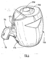
- the figure 1 represents an elongated tank body 1 having a cylindrical main portion 10 and two lower 11 and upper 12 substantially domed ends.
- the upper rounded end 12 has a filling head 2 and distribution.
- the filling and dispensing head 2 comprises in particular a connection interface 3, a status indicator of the capacity 4, an anti-shock shield 5 and a central orifice 6 giving access to the interior of the reservoir 1.
- the tank 1 comprises a tight inner envelope 13 (or "liner"), for example aluminum alloy or the like for containing the fluid and in particular pressurized gas.
- the casing 13 is reinforced on its outer surface by a winding of yarns 14 of carbon fibers bonded with epoxy resin or any other similar means.
- a filling head 2 and oblong distribution is disposed in the tank 1, at the orifice of the tank 1, inside the casing 13.
- the body 20 of the filling and dispensing head 2 is mechanically connected to the casing 13 by means of a threading 21 cooperating with a thread formed on the casing 13.
- An annular seal 7 is arranged in a groove formed in the casing 13. 13. The groove is located at the upper end of the casing 13 and is closed by the body 20 of the filling head 2 and distribution, so as to ensure the insulation between the body 20 and the interior of the tank 1.
- the filling and dispensing head 2 comprises in its lower part a pre-expansion cartridge 22 which is screwed into its body 20 by means of a threading / tapping system 221.
- the filling and dispensing head 2 Downstream of the pre-expansion cartridge 22 (towards the top of the cartridge 2), the filling and dispensing head 2 comprises a low pressure chamber 23.
- the seal between the inside of the tank 1 and the low pressure chamber 23 is provided by the association 222 of an O-ring and anti-extrusion rings disposed between the cartridge 22 and the body 20 of the head 2.
- the pre-expansion cartridge 22 comprises, from upstream to downstream (that is from its lower part to its upper part on the figure 2 ) a filter 24, and a valve 26 of pre-expansion.
- the filter 24 is held in the cartridge 22 by an elastic ring 241 housed in a groove 223 formed in the body of the cartridge 22.
- valve 26 pre-expansion is subjected to the action of a spring 261 to a seat 27 held in the cartridge 22 under the action of threaded seat holder 271.
- the valve 26 is subject to the force of the respect of valve 261 and the force of the gas under pressure.
- the upper end of the valve 26 is provided with an upwardly extending rod 261 whose end is in contact with a pre-expansion piston 28.
- the piston 28 is subject to a constraint on the part of of a spring 281 in direction of the valve 26. Due to the force of the spring 281 and the action of the gas on the section 282 of the piston 28, the valve 26 provides a pressure regulating role.
- the gas contained in the tank 1 under high pressure passes by relaxing through the pre-expansion cartridge 22 to the low pressure chamber 23.
- connection interface 3 is mounted at the level of the upper end of the head 2.
- the chamber 32 comprises an isolation valve 8 having a seal with the interior of the reservoir provided by a seal 81 with the body 30 of the connection interface 3.
- the isolation valve 8 is closed by default.
- the isolation valve 8 is for example a valve of conventional type, such as a valve comprising a fixed tubular body and a movable bronchus within the body adapted to make the valve passing or not depending on the position of the spindle.
- the valve 8 is operable via a valve sprocket described in more detail below and belonging to a receiving system of the storage assembly or a gas distribution head or a conditioning outlet.
- connection interface 3 protrudes outside the filling and dispensing head 2 and the tank 1.
- connection interface 3 comprises four protruding pins 35 (bayonets), positioned at 90 ° to each other to allow attachment of a receiving system of a storage assembly or a gas distribution head or conditioning outlet.
- protruding pins 35 bayonets
- this exemplary embodiment is not limiting, in particular because of the large number of combinations of numbers and possible pin positions and corresponding keying (ie geometric identity) possibilities.
- other clipping means providing the same function are possible such as a screw / nut connection, a knee, a retractable latch, etc ...
- connection interface 3 comprises a tubular housing forming a receiving zone 36 responsible for receiving and guiding a conjugated tubular end of a recipient system or a gas distribution head or a conditioning outlet as described below.
- the conjugate tubular end of the control member intended to be connected to the tank 1 comprises for this purpose and preferably an O-ring and possibly an anti-extrusion ring to ensure the continuity of the seal between the control device. and the tank 1.
- connection interface 3 preferably comprises a removable protective membrane 33 intended to prevent the entry of particles or dirt into the receiving zone 36 which may cause malfunctions of the system.
- the membrane 33 is for example of precut shape memory polymer.
- the membrane is for example maintained at the entrance to the receiving zone 36 by a shock shield 34 made of plastic.
- any other embodiment can be envisaged to protect the entrance of the reception zone, for example a punching cap, or a sticker to be removed.
- the precut membrane 33 will be erased against the surface 37 of the connection interface 3.
- the membrane 33 of shape memory protection is pre-cut according to four lobes shaped "petals".
- the male tubular end of a control device will push the four lobes against the surface 37 of the connection interface 3.
- the lobes automatically return to their original place ( figure 3 ) during the extraction of this same tubular end.
- the tank 1 comprises a status indicator 4 comprising a body 41 screwed into the body 20 of the device of the head 2 of filling and dispensing by means of a threaded system 47.
- the seal between the status indicator and the filling head 2 is provided by means of a constrained metal seal 42.
- a movable axis 43 is guided in the body 41 of the status indicator 4.
- the seal between the axis 43 and the body 41 being formed by the 45 combination of an O-ring and an anti-extrusion ring.
- the axis 43 of the status indicator 4 is subjected to the opposing forces of a return spring 44 and the pressure of the gas contained in the tank 1 conveyed in the control 4 via a thread 21 and holes 46.
- the end of the axis 43 appears in a viewing chamber 48 formed in the body 41 of the status indicator 4. way, the status indicator indicates that the gas storage is full (gas pressure contained in the tank 1 optimal). In the opposite case, the end of the axis 43 does not appear in a viewing chamber 48, which indicates that the gas storage is not full (the pressure of the gas contained in the tank 1 is less than optimal pressure).
- a safety device (thermal fuse type and / or discharge valve, rupture disc, etc .7) can equip the tank 1 via a port 9 formed in the body 20 of the head 2 filling and distribution. This safety device can be fed by the gas contained in the tank 1 via a groove 92 machined in the thread 21 and via holes 91.
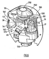
- the figures 3 and 4 illustrate a removable gas delivery head 150 comprising an opening control of the gas flow 250, an annular button for closing the gas flow 350, an access 105 to the outlet connection naturally closed by a shutter 54 avoiding pollution and a Connection interface 516.
- the gas delivery head 150 also includes exhaust louvers 115 of medium and low pressure relief valves.
- the figure 4 illustrates the gas delivery head 150 equipped with an outlet fitting 75 whose port 70 is connected to a fluid supply hose (not shown).
- the connector is adapted to be removably connected in an orifice 105 of the delivery head.
- the figure 5 represents the detail of the gas delivery head according to the same embodiment.
- the protective casing of the delivery head 150 is composed of two half-shells 511 linked together by clips and two screws 135.
- the delivery head 150 contains on the one hand a body 512 comprising the various active delivery members of gas and secondly the interface commands with the user.
- the delivery head 150 comprises an opening control of the gas flow 250, an annular closing button of the gas flow 350, an access 105 to the outlet connection 75.
- the lower part of the body 512 is terminated by a tubular end 514 having an O-ring 515 and a part of revolution 516 here having four countersinks 161 positioned at 90 °.
- a tubular end 514 having an O-ring 515 and a part of revolution 516 here having four countersinks 161 positioned at 90 °.
- the invention is not limited to this configuration and any other combination of numbers and positions of countersinks can be considered.
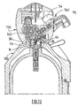
- the lower part of the body 512 forms a connection interface that can cooperate and bond with the connection interface of a tank 1 as described above, as illustrated in FIG. figure 12 .
- the delivery head of the gas 150 docked and extended a protective sheath 100 of the tank 1.
- the body 512 is traversed by a valve sprocket 17 having a dynamic seal with said body 512 through an O-ring.
- the upper end of the valve plunger 17 comes into contact with the axis surface of the gas flow opening control 250 when the latter is pressed and locked.
- the axis of the opening control of the gas flow 250 can thus transmit a translational movement to the valve sprocket 17 which itself carries this translational movement on the valve stem 8 of the tank 1 described above.
- the valve sprout 17 then protrudes beyond the lower part of the body 512 to enter the head 2 of the tank 1, to achieve the opening of the gas flow.
- the fluid stored in the tank 1 then enters the body 512 through the annular orifice 121.
- the annular orifice 121 feeds simultaneously, via the transverse bore 122, a medium pressure safety valve 123 and an expansion stage 58.
- expansion stage 58 comprises a mechanism enclosed in a cartridge 88 which is screwed into the body 512 and sealed therewith by an O-ring.
- the medium pressure safety valve 123 comprises a discharge valve 124 whose opening is determined by the setting force of a spring 125.
- the medium pressure safety valve 123 is shaped to let the excess pressure escape through the louvers. 115 formed in the two half-shells 511.
- the gas inlet into the expansion stage 58 is through the passage of a filter 881 maintained by an elastic ring 582 trapped in a groove in the body 512.
- the gas inlet in the expansion stage 58 is also achieved by the passage around a spacer 83 allowing a radial and homogeneous fluid inlet on a relief valve 84.
- the expansion valve 84 cooperates with a seat 86.
- the seat 86 is held in the cartridge 88 under the action of a seat seat threaded P7.
- the expansion valve 84 is provided with an upwardly extending rod 841 whose end is in contact with a metal bellows 89.
- the metal bellows 89 is held in a sealed manner in the body 512 under the combined action of a screw cap 894 and an O-ring 893.
- the valve 84 is subjected to the force of an expansion spring 891 prestressed by an expansion screw 892 and the force of the gas on the section of the metal bellows 89 In this way, the expansion valve 84 provides pressure regulation.
- the expansion screw 892 is adjustable to allow the user to vary the spring force and therefore the pressure regulation.
- a bore (not shown) formed in the body 512 can ensure the transit of the gas expanded from inside the metal bellows 89 to an outlet connection 95.
- this bore in the body 512 can ensure the transit of the gas expanded between the metal bellows 89 and a low pressure relief valve (not shown and for example of the same type as the valve 123 described above).
- the opening instructions of the two relief valves can be chosen according to the needs of the application.
- An outlet connection 95 is screwed tightly into the body 512.
- This male output connection comprises a skirt 591 enclosing a shutter 592 which is closed by default and sealed with said skirt 591 by the action of a spring 93.
- L shutter 592 prevents firstly the entry of particles and dirt into the gas circuit when the outlet fitting 75 is not connected.
- the shutter 592 prevents a flow of fluid to the atmosphere in the event of a forced action on the opening control 250 while the outlet fitting 75 is not connected, or in case of disconnection of the connection 75.
- the outlet fitting 75 is composed of a body 71 enclosing a shutter 72.
- the shutter 72 is subjected to the action of a spring 73 so as to be closed by default and sealed with said body 71.
- This shutter 72 prevents on the one hand the entry of particles and dirt into the gas circuit when the outlet fitting 75 is not connected and also prevents the purging of the fluid contained in the pipe into the atmosphere. supplying the application in case of disconnection of said output connector 75.
- the outlet fitting 75 is connected to the male output connection 95, on the one hand the circuit becomes sealed under the action of an O-ring and on the other hand the circuit opens thanks to the mutual actions of the two shutters 72 and 592.
- the orifice 105 of the head 150 comprises inside it a male connection device 95 intended to cooperate with a complementary connection device carried by a connector 75.
- a male connection device 95 intended to cooperate with a complementary connection device carried by a connector 75.
- the figure 8 shows the detail of the gas delivery head 150 according to the same embodiment and the on-off device equipped with its connection of At the time of connection, the outlet connection 75 rotates a shutter 54 relative to an axis 38 secured to the body 150.
- the cam profile 542 of the flap 54 pushes a fork 55.
- the fork 55 is guided in translation relative to the body 150 by means of a groove 101 (cf. figure 6 and 7 ).
- the locking fork 55 is kept in contact on the cam profile 542 by a tension spring 412.
- This tension spring 412 is hooked on the one hand on the axis 38 of rotation of the flap 54 and, on the other hand, on an axis 513 secured to the fork 55.
- the fluid delivery system can be started and locked.
- the figure 9 shows the detail of the gas delivery head 150 according to the same embodiment and the on-off device equipped with its outlet connector 75 in the unlocked position for disconnection.
- the flap 54 has a portion forming an unlocking trigger 541 accessible from the outside.
- the action maintained on the trigger 541 for unlocking forces the shutter shutter 54 to open in rotation about the axis 38 until it stops the cam profile 542 on a bearing surface 102 of the body 150.
- the shutter 54 exits and a conjugate housing 142 formed on the outer surface of the connector.
- the outlet fitting 75 is thus unlocked and can be disconnected.
- the shutter 54 Upon extraction of the outlet fitting 75 and the action released on the unlocking trigger 541, the shutter 54 closes by the action of an angular spring 57 (cf. figures 6 and 9 ). The shutter 54 then drives the locking fork 55 is in the stop position of the device. This is achieved by the fact that the locking fork 55 kept in contact with the cam profile 542 via the tension spring 412.
- the figures 10 and 11 illustrate the detail of the gas delivery head 150 according to the same embodiment and the on / off device equipped with its outlet connector 75.
- the locking fork 55 is indexed in the start-up position of the system (see connection of the outlet fitting 75 in figure 8 ).
- the start button 250 comprises a rod provided with a cone 532 ( figure 11 ).
- the cone 532 integral with the rod separates two elastic blades 51 forming the body of the locking fork 55 ( figure 10 ).
- the cone 532 integral with the rod separates the two elastic blades 51 until completely beyond them.
- the action exerted on the button 250 can be stopped as soon as it reaches the stop. With the cone 532 passed, the elastic strips 51 return to their original shapes and hold the rod at the base of the cone 532. The end of the stem 31 of the start-up button 250 then holds the positon pressed against the valve pushrod. 17.
- the annular stop button 350 comprises a cone 521 able to move the elastic blades 51 away from the fork ( figure 11 ). By applying a determined pressure on the annular stop button 350, the cone 521 stops forcing the spacing of the elastic blades 51 releasing the cone 532 start.
- the spring 411 held so far in compression can then reposition the switch button 250 in the off position.
- the axis of the cone 521 stop is shifted transversely of the cone 532 start.
- the cone 521 stop could be coaxial with the cone 532 start.
- the pressure exerted on the annular stop button 350 can then be stopped.
- a spring 56 cooperating with the annular stop button 350 reposition the latter in the relaxed position.
- Two flats 122 may be provided on the stop button 350 for its mounting and in particular for its indexing and that of the cone 521.
- the invention thus makes it possible to manage the conditions for authorizing the delivery of gas from a gas delivery device.
- the invention also provides protection for the outlet of the delivery device.
- the system according to the invention thus forms a circuit breaker in which the button 250 for starting (that is to say, authorizing the delivery of gas) can only remain engaged if the conditions of -connection-are -respected. This start button 250 disrupts if these connection conditions are no longer met.
- the protection of the output connector is designed so that it also gives the status information connected or not.
- the invention can relate to all applications requiring a high level of security, ease of use, good visibility of the state of the system, a good compromise lightness.
- the invention can be applied to the storage and distribution of hydrogen for portable or mobile fuel cells, medical gases, gases for analyzes and laboratories.
Abstract
Description
La présente invention concerne un dispositif de commande du remplissage et/ou du soutirage de fluide ainsi qu'un ensemble comprenant un réservoir et un tel dispositif. Un example de dispositif de commande du remplissage et/ou du soutirage est divulgué dans le document
L'invention concerne plus particulièrement un dispositif-de-commande du remplissage et/ou du soutirage de fluide à partir notamment d'un réservoir de fluide sous pression comportant un corps ayant une extrémité de connexion pourvue de moyens d'accrochage destinés à coopérer avec des moyens d'accrochages complémentaires, notamment d'une interface de connexion d'un réservoir, un organe d'ouverture de vanne mobile relativement au corps, des moyens d'actionnement aptes à déplacer sélectivement l'organe d'ouverture, les moyens d'actionnement étant mobiles entre une position de marche et une position d'arrêt correspondant respectivement à une position de travail et une position de repos de l'organe d'ouverture, un orifice destiné à accueillir un raccord de sortie ou d'arrivée pour assurer la distribution de fluide depuis ou vers le réservoir.The invention relates more particularly to a device for controlling the filling and / or withdrawal of fluid from, in particular, a pressurized fluid reservoir comprising a body having a connection end provided with attachment means intended to cooperate with complementary hooking means, in particular a connection interface of a tank, a valve opening member movable relative to the body, actuating means adapted to selectively move the opening member, the means for actuating being movable between a running position and a stopping position respectively corresponding to a working position and a rest position of the opening member, an orifice intended to accommodate an outlet or arrival fitting to ensure the distribution of fluid from or to the reservoir.
Un besoin est la diffusion large à un public de non-spécialiste de systèmes nécessitant l'utilisation de gaz. (professionnels tels qu'infirmières, laborantins par exemple ou grand public tels que des bricoleurs, automobilistes,..).One need is broad dissemination to a non-specialist public of systems requiring the use of gas. (professionals such as nurses, laboratory technicians for example or general public such as handymen, motorists, ..).
Un objectif des systèmes de stockage de fluide et de leurs dispositifs de remplissage et/ou de soutirage est de rendre faciles les manipulations nécessitées par l'action d'échanger un réservoir plein contre un réservoir vide. Les systèmes de stockage doivent de plus assurer implicitement un niveau de sécurité rendant possible ces manipulations par des non specialistes, tout en permettant d'améliorer la sécurité et la productivité dans des centres de conditionnement.An objective of the fluid storage systems and their filling and / or withdrawal devices is to make easy the manipulations required by the action of exchanging a full tank against an empty tank. In addition, the storage systems must implicitly provide a level of security that makes it possible for these non-specialists to handle them, while at the same time improving safety and productivity in packaging centers.
Un problème à résoudre par ces systèmes est la simplification et la sécurisation d'un dispositif associé à-un raccord de sortie d'un système délivrant du gaz (par exemple sans utilisation d'outil).A problem to be solved by these systems is the simplification and securing of a device associated with an outlet connection of a system delivering gas (for example without the use of a tool).
Il y a donc nécessité de rendre évidentes les manipulations liées à l'ouverture et la fermeture d'un système délivrant du gaz tout en assurant que la délivrance ne soit effective que quand toutes les conditions de sécurité sont réunies. En effet, ces systèmes doivent pouvoir empêcher la diffusion du gaz dans l'environnement direct de l'utilisateur.There is therefore a need to make obvious the manipulations related to the opening and closing of a system delivering gas while ensuring that the delivery is only effective when all security conditions are met. Indeed, these systems must be able to prevent the diffusion of the gas in the direct environment of the user.
Par ailleurs, un autre problème posé par les systèmes actuels réside dans le fait qu'il arrive que les raccords de sortie soient pollués (par exemple par des salissures ou parce que des insectes y font leur nid).On the other hand, another problem posed by current systems is that the outlet connections are sometimes polluted (for example by dirt or because insects are nesting there).
Un but de la présente invention est de pallier tout ou partie des inconvénients de l'art antérieur relevés ci-dessus.An object of the present invention is to overcome all or part of the disadvantages of the prior art noted above.
A cette fin, le dispositif de commande du remplissage et/ou du soutirage de fluide à partir notamment d'un réservoir de fluide sous pression selon l'invention, par ailleurs conforme à la définition générique qu'en donne le préambule ci-dessus, est essentiellement caractérisé en ce qu'il comporte des moyens de verrouillage escamotables des moyens d'actionnement dans la position marche, les moyens de verrouillage escamotables étant conformés de façon à coopérer avec l'orifice, de façon que, lorsque qu'un raccord n'est pas connecté au dispositif de commande dans l'orifice, les moyens de verrouillage sont sollicités vers leur position escamotée, empêchant le maintien stable des moyens d'actionnement dans la position marche.To this end, the device for controlling the filling and / or withdrawal of fluid from, in particular, a pressurized fluid reservoir according to the invention, which moreover complies with the generic definition given in the preamble above, is essentially characterized in that it comprises retractable locking means of the actuating means in the on position, the retractable locking means being shaped so as to cooperate with the orifice, so that when a coupling n is not connected to the control device in the orifice, the locking means are biased towards their retracted position, preventing stable holding of the actuating means in the on position.
Par ailleurs, l'invention peut comporter l'une ou plusieurs des caractéristiques suivantes :
- les moyens de verrouillage escamotables sont conformés de façon que, lorsque qu'un raccord est connecté au dispositif de commande dans l'orifice, un témoin de connexion transmet un effort aux moyens de verrouillage de façon à maintenir ces derniers dans une position active de verrouillage des moyens d'actionnement dans la position de marche.
- le dispositif comporte des moyens intermédiaires assurant la transmission de l'effort de maintien aux moyens de verrouillage ; les moyens intermédiaire de transmission comportant un organe mobile comprenant une première extrémité apte à venir coopérer en butée avec un raccord dans l'orifice et une seconde extrémité apte à venir coopérer en butée avec les moyens de verrouillage escamotables.
- lorsque qu'un raccord -est déconnecté et sorti de l'orifice, l'effort de maintien aux moyens de verrouillage est supprimé automatiquement, les moyens de verrouillage étant escamotés pour commuter les moyens d'actionnement dans la position d'arrêt.
- les moyens d'actionnement comportent un interrupteur mobile en translation.
- le dispositif comporte des moyens de rappel sollicitant les moyens de verrouillage vers la position escamotée.
- le dispositif comporte un obturateur apte à être déplacé entre des positions d'ouverture et de fermeture de l'orifice pour le raccord et en ce que l'obturateur constitue l'organe mobile des moyens intermédiaires de transmission de l'effort de maintien aux moyens de verrouillage.
- l'obturateur comporte une portion d'accrochage, en position d'ouverture de l'obturateur, la portion d'accrochage faisant saillie dans l'orifice de façon à permettre sa coopération en accrochage avec une portion conjuguée d'un raccord.
- le dispositif comporte des moyens de fermeture destinés à commander le déplacement de l'organe vers sa position de repos.
- les moyens de verrouillage comportent une portion d'accrochage élastique, la portion d'accrochage élastique et les moyens d'actionnement ayant des formes conjuguées de façon que lorsque les moyens de verrouillage sont en position active de verrouillage, le déplacement des moyens d'actionnement vers la position de marche provoque l'accrochage de la portion élastique et des moyens d'actionnement.
- les moyens de fermeture sont mobiles entre une position inactive et une position active, en position active, les moyens de fermeture coopérant avec les moyens d'actionnement pour déplacer et/ou déformer de la portion d'accrochage élastique et ainsi libérer le verrouillage des moyens d'actionnement.
- the retractable locking means are shaped so that, when a connector is connected to the control device in the orifice, a connection indicator transmits a force to the locking means so as to keep the latter in an active locking position actuating means in the operating position.
- the device comprises intermediate means ensuring the transmission of the holding force to the locking means; the intermediate transmission means comprising a movable member comprising a first end adapted to cooperate in abutment with a connection in the orifice and a second end adapted to cooperate abutting with the retractable locking means.
- when a coupling is disconnected and out of the orifice, the holding force of the locking means is automatically removed, the means latch being retracted to switch the actuating means in the off position.
- the actuating means comprise a movable switch in translation.
- the device comprises biasing means biasing the locking means to the retracted position.
- the device comprises a shutter capable of being displaced between the opening and closing positions of the orifice for the connection and in that the shutter constitutes the movable member of the intermediate means for transmitting the holding force to the means locking.
- the shutter comprises a hooking portion, in the open position of the shutter, the hooking portion projecting into the orifice so as to allow its cooperation in engagement with a conjugate portion of a coupling.
- the device comprises closure means for controlling the movement of the member towards its rest position.
- the locking means comprise an elastic hooking portion, the elastic hooking portion and the actuating means having conjugate shapes so that when the locking means are in the active locking position, the movement of the actuating means towards the running position causes the attachment of the elastic portion and the actuating means.
- the closing means are movable between an inactive position and an active position, in the active position, the closing means co-operating with the actuating means for moving and / or deforming the elastic hooking portion and thus releasing the locking means actuating.
Un autre but de l'invention est de proposer un ensemble réservoir de fluide sous pression et dispositif de commande le réservoir comprenant une enveloppe délimitant un volume de stockage et pourvu d'un orifice permettant la communication avec l'intérieur du réservoir une tête de remplissage et de distribution disposée au niveau de l'orifice, un organe d'isolement tel qu'une valve, une interface de connexion destinée à coopérer de façon amovible avec un dispositif de commande, le dispositif de commande étant conforme à l'une quelconque des caractéristiques précédentes ou suivantes.Another object of the invention is to propose a set of pressurized fluid reservoir and control device the reservoir comprising an envelope defining a storage volume and provided with an orifice allowing communication with the interior of the reservoir a filling head and a distribution device disposed at the orifice, an isolating member such as a valve, a connection interface intended to cooperate in a detachable manner with a control device, the control device being in conformity with any of the previous or following features.
D'autres particularités et avantages apparaîtront à la lecture de la description ci-après, faite en référence aux figures dans lesquelles :
- la
figure 1 représente une vue extérieure en perspective isométrique d'un exemple de réalisation d'un réservoir selon l'invention, - la
figure 2 est une vue en coupe longitudinale à plus grande échelle de la partie supérieure du réservoir de lafigure 1 , - les
figures 3 et4 sont des vues extérieures en perspective isométrique d'un exemple de réalisation d'une tête de délivrance de fluide selon l'invention avec, à lafigure 4 , un raccord de sortie connecté, - la
figure 5 est une vue en coupe longitudinale de la tête de délivrance de lafigure 4 équipée de son raccord de sortie; - la
figure 6 est une vue en perspective isométrique illustrant l'intérieur de la tête de délivrance sans son raccord de sortie, - la
figure 7 est une vue en coupe longitudinale illustrant l'intérieur de la tête de délivrance sans son raccord de sortie, - la
figure 8 est une vue en coupe longitudinale de la tête de délivrance équipée de son raccord de sortie et en position d'arrêt; - la
figure 9 est une vue en coupe longitudinale de la tête de délivrance équipée de son raccord de sortie en position déverrouillée, - les
figures 10 et11 représentent des vues respectivement en perspective isométrique en coupe longitudinale de la tête de délivrance équipée de son raccord de sortie et en position de marche, - la
figure 12 est une vue en coupe longitudinale de la tête de délivrance équipée de son raccord de sortie et montée sur un réservoir selon lafigure 2 .
- the
figure 1 represents an external perspective view in isometric perspective of an exemplary embodiment of a tank according to the invention, - the
figure 2 is a longitudinal sectional view on a larger scale of the upper part of the tank of thefigure 1 , - the
figures 3 and4 are external views in isometric perspective of an exemplary embodiment of a fluid delivery head according to the invention with, at thefigure 4 , a connected output connection, - the
figure 5 is a longitudinal sectional view of the delivery head of thefigure 4 equipped with its outlet fitting; - the
figure 6 is an isometric perspective view illustrating the interior of the delivery head without its outlet fitting, - the
figure 7 is a longitudinal sectional view illustrating the interior of the delivery head without its outlet connection, - the
figure 8 is a longitudinal sectional view of the delivery head equipped with its outlet connection and in the off position; - the
figure 9 is a longitudinal sectional view of the delivery head equipped with its outlet connection in the unlocked position, - the
figures 10 and11 represent views respectively in isometric perspective in longitudinal section of the delivery head equipped with its output connection and in the running position, - the
figure 12 is a longitudinal sectional view of the delivery head equipped with its outlet fitting and mounted on a tank according to thefigure 2 .
La
En se référant à présent à la
Une tête 2 de remplissage et de distribution oblongue est disposée dans le réservoir 1, au niveau de l'orifice du réservoir 1, à l'intérieur de l'enveloppe 13.A filling
Le corps 20 de la tête de remplissage et de distribution 2 est lié mécaniquement à l'enveloppe 13 grâce à un filetage 21 coopérant avec un taraudage formé sur l'enveloppe 13. Un joint 7 annulaire est disposé dans une gorge ménagée dans le l'enveloppe 13. La gorge est située à l'extrémité supérieure de l'enveloppe 13 et est refermée par le corps 20 de la tête 2 de remplissage et de distribution, de façon à assurer l'isolation entre le corps 20 et l'intérieur du réservoir 1.The
La tête 2 de remplissage et de distribution comprend dans sa partie inférieure une cartouche de pré-détente 22 qui est vissée dans son corps 20 grâce à un système de filetage/taraudage 221.The filling and dispensing
En aval de la cartouche de pré-détente 22 (vers le haut de la cartouche 2), la tête 2 de remplissage et de distribution comprend une chambre basse pression 23. L'étanchéité entre l'intérieur du réservoir 1 et la chambre basse pression 23 est assurée par l'association 222 d'un joint torique et de bagues anti-extrusion disposés entre la cartouche 22 et le corps 20 de la tête 2.Downstream of the pre-expansion cartridge 22 (towards the top of the cartridge 2), the filling and dispensing
La cartouche de pré-détente 22 comporte, d'amont en aval (c'est-à-dire de sa partie inférieure vers sa partie supérieure sur la
Le clapet 26 pré-détente est soumis à l'action d'un ressort 261 vers un siège 27 maintenu dans la cartouche 22 sous l'action du porte-siège fileté 271. Le clapet 26 est soumis à l'effort du respect de clapet 261 et à l'effort du gaz sous pression.The
L'extrémité supérieure du clapet 26 est munie d'une tige 261 s'étendant vers le haut dont l'extrémité est en contact avec un piston de pré-détente 28. Le piston 28 est soumis quant à lui à une contrainte de la part d'un ressort 281 en direction du clapet 26. Du fait de l'effort du ressort 281 et de l'action du gaz sur la section 282 du piston 28, le clapet 26 assure un rôle de régulation de pression.The upper end of the
Lors des phases de soutirage de gaz à partir du réservoir 1, le gaz contenu dans le réservoir 1 sous haute pression transite en se détendant par la cartouche de pré-détente 22 vers la chambre basse pression 23.During the phases of gas withdrawal from the tank 1, the gas contained in the tank 1 under high pressure passes by relaxing through the
Le gaz détendu traverse ensuite le piston 28 par un perçage 283 formé dans le corps du piston, pour déboucher dans une chambre 32 située dans le corps 30 d'une l'interface de connexion 3. L'interface de connexion est montée au niveau de l'extrémité supérieure de la tête 2.The expanded gas then passes through the
La chambre 32 comprend une valve d'isolement 8 ayant une étanchéité avec l'intérieur du réservoir assurée par un joint 81 avec le corps 30 de l'interface de connexion 3.The
La valve 8 d'isolement est par défaut fermée. La valve 8 d'isolement est par exemple une valve de type classique, telle qu'une valve comportant un corps tubulaire fixe et une bronche mobile à l'intérieur du corps apte à rendre la valve passante ou non suivant la position de la broche.The
La valve 8 est susceptible d'être actionnée via un pousse-valve décrit plus en détail ci-après et appartenant à un système receveur de l'ensemble de stockage ou à une tête de distribution du gaz ou à une prise de conditionnement.The
L'extrémité supérieure de l'interface de connexion 3 fait saillie à l'extérieur de la tête 2 de remplissage et de distribution et du réservoir 1.The upper end of the
Cette partie extérieure de l'interface de connexion 3 comporte quatre goupilles protubérantes 35 (baïonnettes), positionnées à 90° l'une de l'autre pour permettre l'accrochage d'un système receveur d'un ensemble de stockage ou d'une tête de distribution du gaz ou d'une prise de conditionnement. Bien entendu, cet exemple de réalisation n'est pas limitatif du fait notamment du nombre important de combinaisons de nombres et positions de goupilles envisageables et de possibilités de détrompage (c'est à dire d'identité géométrique) correspondants. De plus, d'autres moyens d'accrochages assurant la même fonction sont envisageables tels qu'une liaison vis / écrou, une genouillère, un verrou escamotable, etc ...This outer portion of the
-- La partie extérieure de l'interface de connexion 3 comporte un logement tubulaire formant une zone de réception 36 chargée de recevoir et de guider une extrémité tubulaire conjuguée d'un système receveur ou d'une tête de distribution du gaz ou d'une prise de conditionnement comme décrit ci-après.- The outer part of the
L'extrémité tubulaire conjuguée de l'organe de commande destiné à être connecté au réservoir 1 comprend à cet effet et de préférence un joint torique et éventuellement d'une bague anti-extrusion pour assurer la continuité de l'étanchéité entre le dispositif de commande et le réservoir 1.The conjugate tubular end of the control member intended to be connected to the tank 1 comprises for this purpose and preferably an O-ring and possibly an anti-extrusion ring to ensure the continuity of the seal between the control device. and the tank 1.
La partie extérieure de l'interface de connexion 3 comporte de préférence une membrane 33 de protection amovible destinée à éviter l'entrée de particules ou salissures dans la zone de réception 36 pouvant entraîner des dysfonctionnements du système. La membrane 33 est par exemple en polymère à mémoire de forme prédécoupée. La membrane est par exemple maintenue au niveau de l'entrée de la zone de réception 36 par un bouclier anti-chocs 34 en plastique. Bien entendu, toute autre forme de réalisation est envisageable pour protéger l'entrée de la zone de réception, par exemple un opercule à poinçonner, ou un autocollant à ôter.The outer part of the
Ainsi, lors de l'introduction de l'extrémité tubulaire d'un dispositif de commande (système receveur ou tête de distribution de gaz ou prise de conditionnement) dans la zone de réception 36, la membrane prédécoupée 33 va s'effacer contre la surface 37 de l'interface de connexion 3. Par exemple, la membrane 33 de protection à mémoire de forme est prédécoupée selon quatre lobes en forme de « pétales ». L'extrémité tubulaire mâle d'un dispositif de commande va repousser les quatre lobes contre la surface 37 de l'interface de connexion 3. Les lobes retrouvent automatiquement leur place originelle (
Le réservoir 1 comporte un témoin d'état 4 comprenant un corps 41 vissé dans le corps 20 du dispositif de la tête 2 de remplissage et de distribution au moyen d'un système à filetage 47. L'étanchéité entre le témoin d'état et la tête 2 de remplissage est assurée au moyen d'un joint métallique contraint 42. Un axe 43 mobile est guidé dans le corps 41 du témoin d'état 4. L'étanchéité entre l'axe 43 et le corps 41 étant réalisée par l'association 45 d'un joint torique et d'une bague anti-extrusion.The tank 1 comprises a status indicator 4 comprising a
L'axe 43 du témoin d'état 4 est soumis aux efforts antagonistes d'un ressort de rappel 44 et de la pression du gaz contenu dans le réservoir 1 acheminé dans le témoin 4 via un filetage 21 et des perçages 46.The axis 43 of the status indicator 4 is subjected to the opposing forces of a
Lorsque l'action de la pression du gaz est supérieure à l'effort du ressort de rappel 44, l'extrémité de l'axe 43 apparaît dans une chambre de visualisation 48 formée dans le corps 41 du témoin d'état 4. De cette façon, le témoin d'état indique que le stockage de gaz est plein (pression du gaz contenu dans le réservoir 1 optimale). Dans le cas contraire, l'extrémité de l'axe 43 n'apparaît pas dans une chambre de visualisation 48, ce qui indique que le stockage de gaz n'est pas plein (la pression du gaz contenu dans le réservoir 1 est inférieure à la pression optimale).When the action of the gas pressure is greater than the force of the
Un dispositif de sécurité (de type fusible thermique et/ou soupape de décharge, disque de rupture, etc....) peut équiper le réservoir 1 via un port 9 ménagé dans le corps 20 de la tête 2 de remplissage et de distribution. Ce dispositif de sécurité peut être alimenté par le gaz contenu dans le réservoir 1 via une saignée 92 usinée dans le filetage 21 et via des perçages 91.A safety device (thermal fuse type and / or discharge valve, rupture disc, etc ....) can equip the tank 1 via a
Les
La
La
La partie basse du corps 512 est terminée par une extrémité tubulaire 514 ayant un joint torique 515 et une pièce de révolution 516 ayant ici quatre fraisures 161 positionnées à 90°. Bien entendu, l'invention ne se limite pas à cette configuration et toute autre combinaison de nombres et positions de fraisures peut être envisagée.The lower part of the
La partie basse du corps 512 forme une interface de connexion pouvant coopérer et se lier avec l'interface de raccordement d'un réservoir 1 tel que décrit ci-dessus, comme illustré à la
Le corps 512 est traversé par un pousse-valve 17 ayant une étanchéité dynamique avec ledit corps 512 grâce à un joint torique. L'extrémité supérieure du pousse-valve 17 vient en contact avec la surface de l'axe de la commande d'ouverture du débit de gaz 250 lorsque cette dernière est appuyée et verrouillée.The
L'axe de la commande d'ouverture du débit de gaz 250 peut ainsi transmettre un mouvement de translation au pousse-valve 17 qui lui-même reporte ce mouvement de translation sur la tige de valve 8 du réservoir 1 décrit ci-dessus. Le pousse-valve 17 fait alors saillie au-delà de la partie basse du corps 512 pour pénétrer au sein de la tête 2 du réservoir 1, pour réaliser l'ouverture du débit de gaz.The axis of the opening control of the
Le fluide stocké dans le réservoir 1 entre alors dans le corps 512 par l'orifice annulaire 121. L'orifice annulaire 121 alimente simultanément, via le perçage transverse 122, une soupape de sécurité moyenne pression 123 et un étage de détente 58. L'étage de détente 58 comprend un mécanisme enfermé dans une cartouche 88 qui est vissée dans le corps 512 et étanche avec celui-ci grâce à un joint torique.The fluid stored in the tank 1 then enters the
La soupape de sécurité moyenne pression 123 comprend un clapet de décharge 124 dont l'ouverture est déterminée par l'effort de tarage d'un ressort 125. La soupape de sécurité moyenne pression 123 est conformée pour laisser évacuer le surplus de pression par les persiennes 115 ménagées dans les deux demi-coquilles 511.The medium pressure safety valve 123 comprises a
L'entrée du gaz dans l'etage de détente 58 se fait par la traversée d'un filtre 881 maintenu par une bague élastique 582 prisonnière d'une gorge ménagée dans le corps 512. L'entrée du gaz dans l'étage de détente 58 est réalisée également par le passage autour d'une entretoise 83 permettant une arrivée radiale et homogène du fluide sur un clapet de détente 84.The gas inlet into the expansion stage 58 is through the passage of a
Du fait de l'effort d'un ressort de clapet 85 et l'action du gaz, le clapet de détente 84 coopère avec un siège 86. Le siège 86 est maintenu dans la cartouche 88 sous l'action d'un porte siège fileté P7. le clapet de détente 84 est muni d'une tige 841 s'étendant vers le haut dont l'extrémité est en contact avec un soufflet métallique 89. Le soufflet métallique 89 est maintenu de façon étanche dans le corps 512 sous l'action combinée d'un capot vissé 894 et d'un joint torique 893. Le clapet 84 est soumis à l'effort d'un ressort de détente 891 précontraint par une vis de détente 892 et à l'effort du gaz sur la section du soufflet métallique 89. De cette façon, le clapet de détente 84 assure une régulation de pression.Because of the force of a
Avantageusement, la vis de détente 892 est réglable pour permettre à l'utilisateur de faire varier l'effort du ressort et donc la régulation de pression.Advantageously, the
Un perçage (non représenté) formé dans le corps 512 peut assurer le transit du gaz détendu depuis l'intérieur du soufflet métallique 89 vers une connexion de sortie 95. En parallèle, ce perçage ménagé dans le corps 512 peut assure le transit du gaz détendu entre le soufflet métallique 89 et une soupape de décharge basse pression (non représentée et par exemple du même type que la soupape 123 décrite ci-dessus). Les consignes d'ouverture des deux soupapes de décharge peuvent être choisies en adéquation avec les besoins de l'application.A bore (not shown) formed in the
Une connexion de sortie 95 est vissé de façon étanche dans le corps 512. Cette connexion de sortie mâle comprend une jupe 591 enfermant un obturateur 592 qui est par défaut fermé et étanche avec ladite jupe 591 par l'action d'un ressort 93. L'obturateur 592 prévient d'une part l'entrée de particules et de salissures dans le circuit de gaz lorsque le raccord de sortie 75 n'est pas connecté. De plus l'obturateur 592 empêche un débit de fluide à l'atmosphère en cas soit d'une action forcée sur la commande d'ouverture 250 alors que le raccord de sortie 75 n'est pas connecté, soit en cas de déconnexion du raccord de sortie 75.An
Le raccord de sortie 75 est composé d'un corps 71 enfermant un obturateur 72. L'obturateur 72 est soumis à l'action d'un ressort 73 de façon à être fermé par défaut et étanche avec ledit corps 71.The outlet fitting 75 is composed of a
Cet obturateur 72 prévient d'une part l'entrée de particules et de salissures dans le circuit de gaz lorsque le raccord de sortie 75 n'est pas connecté et empêche d'autre part la purge à l'atmosphère du fluide contenu dans le tuyau d'alimentation de l'application en cas de déconnexion dudit raccord de sortie 75. Lorsque le raccord de sortie 75 est connecté sur la connexion de sortie mâle 95, d'une part le circuit devient étanche sous l'action d'un joint torique et d'autre part le circuit s'ouvre grâce aux actions mutuelles des deux obturateurs 72 et 592.This
Avantageusement selon l'invention, et comme décrit plus en détail ci-après, la tête 150 peut être conformée de façon que :
- si le raccord de sortie 75 n'est pas connecté dans l'orifice 105, le verrouillage de la commande d'ouverture du débit de
gaz 250 est impossible, - si le raccord de sortie 75 est connecté sur la tête 150 amovible de délivrance du gaz dans l'orifice 105, le verrouillage de la commande d'ouverture du débit de
gaz 250 est autorisé, l'arrêt de débit de gaz est commandé par une action sur le bouton annulaire 350 et la commande 541 de déverrouillage du raccord de sortie 75 est accessible, - si le raccord de sortie 75 est déconnecté subitement alors que la commande d'ouverture du gaz est active, cette dernière disjoncte instantanément.
- if the outlet fitting 75 is not connected in the
orifice 105, the locking of the opening control of thegas flow 250 is impossible, - if the outlet fitting 75 is connected to the removable
gas delivery head 150 in theorifice 105, the lock of the gasflow opening control 250 is enabled, the gas flow stop is controlled by a action on theannular button 350 and thecontrol 541 for unlocking the outlet fitting 75 is accessible, - if the outlet fitting 75 is suddenly disconnected while the gas opening control is active, it will instantaneously trip.
L'orifice 105 de la tête 150 comprend en son sein un dispositif de connexion 95 mâle destiné à coopérer avec un dispositif de connexion complémentaire porté par un raccord 75. Lors de l'actionnement du bouton de mise en marche 250, le pousse-valve 17 d'ouverture du gaz de l'appareil est activé mais la présence au niveau du dispositif de connexion 95 mâle d'un obturateur 54 interdit tout débit de gaz.The
La
Pendant la rotation du volet 54, le profil came 542 du volet 54 vient pousser une fourchette 55. La fourchette 55 est guidée en translation par rapport au corps 150 au moyen d'une rainure 101 (cf.
La fourchette de verrouillage 55 est maintenue en contact sur le profil de came 542 par un ressort de traction 412. Ce ressort de traction 412 est accroché d'une part sur l'axe 38 de rotation du volet 54 et, d'autre part, sur un axe 513 solidaire de la fourchette 55. Le système de délivrance de fluide peut être mis en marche et verrouillé.The locking
La
Le volet 54 présente une portion formant une gâchette de déverrouillage 541 accessible depuis l'extérieur. L'action maintenue sur la gâchette 541 de déverrouillage force l'ouverture du volet d'obturation 54 en rotation autour de l'axe 38 jusqu'à mettre en butée le profil came 542 sur une portée 102 du corps 150. Le volet 54 sort ainsi d'un logement 142 conjugué formé sur la surface extérieure du raccord. Le raccord de sortie 75 est ainsi déverrouillé et peut être déconnecté.The
Dès l'extraction du raccord de sortie 75 et l'action relâchée sur la gâchette de déverrouillage 541, le volet d'obturation 54 se referme par l'action d'un ressort angulaire 57 (cf.
Les
Différentes situations d'utilisation du dispositif sont décrites ci-dessous.Different situations of use of the device are described below.
La fourchette de verrouillage 55 est indexée en position de mise en marche du système (cf. connexion du raccord de sortie 75 en
L'action exercée sur le bouton 250 peut être stoppée dès son arrivée en butée. Le cône 532 passé, les lames élastiques 51 reprennent leur formes initiales et maintiennent la tige au niveau de la base du cône 532. L'extrémité de la tige 31 du bouton 250 de mise en marche maintient alors la positon enfoncée sur le pousse-valve 17.The action exerted on the
Le bouton annulaire d'arrêt 350 comprend un cône 521 apte à écarter les lames élastiques 51 de la fourchette (
Le ressort 411 maintenu jusqu'ici en compression peut repositionner alors le bouton 250 de mise en marche en position d'arrêt.The
Dans l'exemple représenté, l'axe du cône 521 d'arrêt est décalé transversalement du cône 532 de mise en marche. Bien entendu, en variante, le cône 521 d'arrêt pourrait être coaxial au cône 532 de mise en marche.In the example shown, the axis of the
La pression exercée sur le bouton annulaire d'arrêt 350 peut alors être stoppée. Un ressort 56 coopérant avec le bouton annulaire d'arrêt 350 vient repositionner ce dernier en position relâchée. Deux méplats 122 peuvent être ménagés sur le bouton 350 d'arrêt pour son montage et en particulier pour son indexage et celui du cône 521.The pressure exerted on the
Dans cette configuration le système est arrêté mais toujours connecté via le raccord de sortie 75. Le système peut être de nouveau mis en marche comme précédemment expliqué ou le raccord 75 de sortie peut-être déconnecté de l'orifice 105 comme décrit dans le paragraphe relatif à la
Si le raccord de sortie 75 est déconnecté subitement alors que la commande d'ouverture du gaz est active, la fourchette de verrouillage 55 va reprendre sa position non active. De cette façon, le cône 532 est libéré. Le ressort 411 maintenu jusqu'alors en compression va repositionner le bouton de mise en marche 250 en position relevée d'arrêt (cf. paragraphe relatif à la
L'invention permet ainsi de gérer les conditions d'autorisation de délivrance du gaz d'un dispositif de délivrance de gaz. L'invention permet également une protection l'orifice de sortie du dispositif de délivrance.The invention thus makes it possible to manage the conditions for authorizing the delivery of gas from a gas delivery device. The invention also provides protection for the outlet of the delivery device.
Le système selon l'invention forme ainsi un disjoncteur dans lequel le bouton 250 de mise en marche (c'est-à-dire autorisant la délivrance du gaz) ne peut rester enclenché que si les conditions de -connexion-sont -respectées. Ce bouton de mise en marche 250 disjoncte si ces conditions de connexion ne sont plus respectées.The system according to the invention thus forms a circuit breaker in which the
Dans la solution proposée, la protection du raccord de sortie est conçue de sorte qu'elle donne également l'information d'état connecté ou non.In the proposed solution, the protection of the output connector is designed so that it also gives the status information connected or not.
L'invention, peut concerner toutes les applications demandant un haut niveau de sécurité, une grande facilité d'emploi, une bonne visibilité de l'état du système, un bon compromis légèreté. A titre d'exemple, l'invention peut s'appliquer au stockage et à la distribution d'hydrogène pour pile à combustible portable ou mobile, de gaz médicaux, de gaz pour analyses et laboratoires.The invention can relate to all applications requiring a high level of security, ease of use, good visibility of the state of the system, a good compromise lightness. By way of example, the invention can be applied to the storage and distribution of hydrogen for portable or mobile fuel cells, medical gases, gases for analyzes and laboratories.
Claims (12)
- Device for controlling the filling and/or the extraction of fluid particularly from a tank of pressurized fluid comprising a body having a connection end (516) provided with attachment means intended to collaborate with complementary attachment means, particularly of a tank connection interface, a member (17) for opening a valve that can move relative to the body, actuating means (250) capable selectively of moving the opening member (17), the actuating means (250) being able to move between an on position and an off position which correspond respectively to a work position and a rest position of the opening member (17), an orifice (105) intended to accommodate a removable inlet or outlet coupling (75) for distributing fluid, characterized in that it comprises retractable means (55) of locking the actuating means (250) in the on position, the retractable locking means (55) being configured in such a way as to collaborate with the orifice (105) in such a way that when a coupling (75) is not connected to the control device in the orifice, the locking means (55) are urged into their retracted position preventing the actuating means (250) from remaining stably in the on position.
- Control device according to Claim 1, characterized in that the retractable locking means (55) are configured in such a way that when a coupling (75) is connected to the control device in the orifice, a connection tell-tale (54) transmits a force to the locking means (55) so as to maintain the latter in an active position that locks the actuating means (250) in the on position.
- Control device according to Claim 2, characterized in that it comprises intermediate means (54, 542) that transmit the maintaining force to the locking means (55); the intermediate transmission means (54, 542) comprising a moving member (54) that has a first end capable of collaborating in abutment with a coupling (75) in the orifice (105) and a second end (542) capable of collaborating in abutment with the retractable locking means (55).
- Control device according to Claim 2 or 3, characterized in that when a coupling (75) is disconnected and extracted from the orifice, the maintaining force on the locking means (55) is automatically removed, the locking means (55) being retracted in order to switch the actuating means (250) into the off position.
- Control device according to any one of the preceding claims, characterized in that the actuating means (250) comprise a translationally mobile switch.
- Control device according to any one of the preceding claims, characterized in that it comprises return means (412) urging the locking means (55) toward the retracted position.
- Control device according to Claim 3, characterized in that it comprises a shut-off element (54) capable of being moved between positions in which it opens and closes the orifice (105) for the coupling, and in that the shut-off element (54) constitutes the moving member of the intermediate means (54, 542) for transmitting the maintaining force to the locking means.
- Control device according to Claim 7, characterized in that the shut-off element (54) comprises an attachment portion, when the shut-off element (54) is in the opening position, the attachment portion projecting into the orifice so as to allow it to collaborate for the purposes of attachment with a mating portion belonging to a coupling (75).
- Control device according to any one of the preceding claims, characterized in that it comprises closure means (350) intended to make the member (17) move into its rest position.
- Control device according to any one of Claims 2 to 4, characterized in that the locking means (55) comprise an elastic attachment portion (51), the elastic attachment portion (51) and the actuating means (250) having mating shapes so that when the locking means (55) are in the active locking position the movement of the actuating means (250) toward the on position causes the elastic portion (51) to become attached to the actuating means (250).
- Control device according to Claims 9 and 10, characterized in that the closure means (350) are able to move between an inactive position and an active position, in the active position, the closure means (350) collaborating with the actuating means (250) in order to move and/or to deform the elastic attachment portion (51) and thus release the locking of the actuating means (250).
- Assembly made up of a pressurized-fluid tank and a control device, the tank (1) comprising a casing (13) delimiting a storage volume and provided with an orifice allowing communication with the inside of the tank, a filling and distribution head (2) positioned at the orifice, an isolating member (8) such as an isolating valve, a connection interface (3) intended to collaborate removably with a control device, characterized in that the control device is a control device according to any one of the preceding claims.
Applications Claiming Priority (2)
| Application Number | Priority Date | Filing Date | Title |
|---|---|---|---|
| FR0553265A FR2892799B1 (en) | 2005-10-27 | 2005-10-27 | FLUID FILLING AND / OR SUPPLY CONTROL DEVICE AND TANK COMPRISING SUCH A DEVICE |
| PCT/FR2006/051047 WO2007048952A1 (en) | 2005-10-27 | 2006-10-18 | Fluid filling and/or extraction control device and tank including one such device |
Publications (2)
| Publication Number | Publication Date |
|---|---|
| EP1943458A1 EP1943458A1 (en) | 2008-07-16 |
| EP1943458B1 true EP1943458B1 (en) | 2011-09-07 |
Family
ID=36592871
Family Applications (1)
| Application Number | Title | Priority Date | Filing Date |
|---|---|---|---|
| EP06820305A Active EP1943458B1 (en) | 2005-10-27 | 2006-10-18 | Fluid filling and/or extraction control device and tank including one such device |
Country Status (12)
| Country | Link |
|---|---|
| US (1) | US8136791B2 (en) |
| EP (1) | EP1943458B1 (en) |
| JP (1) | JP2009513904A (en) |
| KR (1) | KR20080069585A (en) |
| CN (1) | CN101297152B (en) |
| AT (1) | ATE523730T1 (en) |
| AU (1) | AU2006307762A1 (en) |
| BR (1) | BRPI0618005A2 (en) |
| CA (1) | CA2637319A1 (en) |
| FR (1) | FR2892799B1 (en) |
| RU (1) | RU2008121180A (en) |
| WO (1) | WO2007048952A1 (en) |
Families Citing this family (30)
| Publication number | Priority date | Publication date | Assignee | Title |
|---|---|---|---|---|
| FR2892798B1 (en) | 2005-10-27 | 2011-02-18 | Air Liquide | ASSEMBLY COMPRISING A PRESSURIZED FLUID RESERVOIR AND A FILLING AND / OR STRAINING CONTROL DEVICE |
| FR2892799B1 (en) | 2005-10-27 | 2007-12-28 | Air Liquide | FLUID FILLING AND / OR SUPPLY CONTROL DEVICE AND TANK COMPRISING SUCH A DEVICE |
| US20090114294A1 (en) * | 2007-10-25 | 2009-05-07 | Rubicon Manufacturing, Inc. | Portable gas shock or air bag inflator or deflator |
| US9027591B2 (en) * | 2009-10-21 | 2015-05-12 | Victor Equipment Company | Gas pressure regulator with particle trap and diffuser |
| FR2956185B1 (en) * | 2010-02-11 | 2012-05-04 | Air Liquide | COMPOSITE TANK AND ASSEMBLY COMPRISING SUCH A RESERVOIR AND A GAS RECEIVER AND / OR DISPENSER ORGAN |
| DE102010003016B4 (en) * | 2010-03-18 | 2018-11-08 | Hyptec Gmbh | Pressure regulator for supplying fuel and fuel supply system with a control unit from these pressure regulators |
| FR2988157B1 (en) * | 2012-03-14 | 2014-04-11 | Air Liquide | TAP FOR STORAGE CONTAINER, CONTAINER HAVING SUCH FAUCET AND USE THEREOF |
| WO2013162526A1 (en) * | 2012-04-24 | 2013-10-31 | International Engine Intellectual Property Company, Llc | Biasing of ammonia lines to facilitate canister removal and insertion |
| GB201309046D0 (en) * | 2013-05-20 | 2013-07-03 | Linde Ag | A pressurised fluid container |
| FR3022972B1 (en) | 2014-06-25 | 2017-08-25 | Air Liquide | DEVICE AND METHOD FOR SUPPLYING FLUID UNDER PRESSURE. |
| JP6421013B2 (en) * | 2014-10-28 | 2018-11-07 | 株式会社ジェイテクト | Throttle valve |
| FR3033387B1 (en) | 2015-03-04 | 2017-10-27 | Air Liquide | PRESSURIZED FLUID SUPPLY DEVICE AND CORRESPONDING FLUID TRANSFER MEMBER |
| FR3033388B1 (en) | 2015-03-04 | 2017-10-27 | Air Liquide | DEVICE FOR SUPPLYING FLUID UNDER PRESSURE |
| FR3052844B1 (en) * | 2016-06-21 | 2018-05-25 | L'air Liquide, Societe Anonyme Pour L'etude Et L'exploitation Des Procedes Georges Claude | GAS DISTRIBUTION ASSEMBLY COMPRISING A COVERAGE AGENCY AROUND A TAP BLOCK EQUIPPED WITH A GAS CONTAINER |
| FR3054291B1 (en) | 2016-07-20 | 2018-11-16 | Air Liquide | DEVICE FOR SUPPLYING FLUID UNDER PRESSURE |
| FR3054639B1 (en) * | 2016-07-29 | 2019-05-10 | L'air Liquide, Societe Anonyme Pour L'etude Et L'exploitation Des Procedes Georges Claude | GAS DISTRIBUTION ASSEMBLY |
| US10843808B2 (en) * | 2016-11-29 | 2020-11-24 | Insitu, Inc. | Methods and apparatus for cryogenic fuel bayonet transfers |
| JP6878040B2 (en) * | 2017-02-20 | 2021-05-26 | 株式会社Soken | Valve device |
| FR3067788A1 (en) * | 2017-06-16 | 2018-12-21 | L'air Liquide, Societe Anonyme Pour L'etude Et L'exploitation Des Procedes Georges Claude | COVERING FOR A GAS CONTAINER CARRYING AN ORDERING MEMBER OF THE INSULATION VALVE OF AN INTEGRATED REGULATOR VALVE |
| GB201711670D0 (en) * | 2017-07-20 | 2017-09-06 | Qinov8 Uk | Safety valve |
| USD867519S1 (en) * | 2017-10-02 | 2019-11-19 | Ini Power Systems, Inc. | Fuel tank |
| FR3081965B1 (en) | 2018-06-04 | 2020-05-08 | L'air Liquide, Societe Anonyme Pour L'etude Et L'exploitation Des Procedes Georges Claude | DEVICE FOR PROVIDING PRESSURE FLUID |
| FR3092644B1 (en) | 2019-02-11 | 2021-01-08 | Air Liquide | Pressurized fluid supply device and pressurized fluid storage assembly (s) comprising such a device |
| FR3092643B1 (en) * | 2019-02-11 | 2021-06-18 | Air Liquide | Pressurized fluid supply device and pressurized fluid storage assembly (s) comprising such a device |
| FR3092894B1 (en) * | 2019-02-20 | 2021-10-15 | Air Liquide | Device for supplying pressurized fluid and bottle (s) for pressurized fluid comprising such a device |
| USD898575S1 (en) * | 2019-04-04 | 2020-10-13 | Societe Anonyme Des Eaux Minerales D'evian | Bottle for water dispensers |
| CN110043798A (en) * | 2019-05-08 | 2019-07-23 | 河南查瑞特种设备有限公司 | A kind of LNG accumulating tank with fire-fighting system |
| FR3122236B1 (en) * | 2021-04-21 | 2023-09-15 | Applic Gaz Sa | Gas appliance connection device |
| US11732843B2 (en) * | 2021-07-19 | 2023-08-22 | Caterpillar Inc. | On-tank regulator for high-pressure tank |
| FR3140924A1 (en) * | 2022-10-18 | 2024-04-19 | L'air Liquide, Societe Anonyme Pour L'etude Et L'exploitation Des Procedes Georges Claude | Fluid delivery device |
Family Cites Families (39)
| Publication number | Priority date | Publication date | Assignee | Title |
|---|---|---|---|---|
| US2756105A (en) | 1953-02-09 | 1956-07-24 | American Can Co | Protective shatterproof outer container for bottle |
| US3035605A (en) * | 1957-12-21 | 1962-05-22 | Ninnelt Fred | Protecting, actuating, and sealing devices for valves in receptacles for gaseous media and the like |
| US3788511A (en) | 1971-08-16 | 1974-01-29 | R Marsh | Protective jacket and base for pressure vessel |
| US3921872A (en) | 1974-04-23 | 1975-11-25 | Jr Clarence E Buell | Gas cylinder carrier |
| US4832398A (en) | 1987-10-02 | 1989-05-23 | Tecca Frank G | Scuba tank holder and carrier |
| US4905855A (en) | 1988-07-08 | 1990-03-06 | Troiano Joseph M | Propane carry safe |
| ES2044466T3 (en) * | 1989-05-29 | 1994-01-01 | Air Liquide | VALVE ASSEMBLY FOR LOW PRESSURE FLUID CONTAINER, AND CONTAINER EQUIPPED WITH SUCH ASSEMBLY. |
| US4964529A (en) | 1989-06-30 | 1990-10-23 | Houston Robert S | Gas tank container |
| LU87671A1 (en) * | 1990-01-31 | 1990-05-15 | Ceodeux Sa | TAP FOR COMPRESSED OR LIQUIFIED GAS |
| FR2664962B1 (en) | 1990-07-17 | 1992-09-18 | Air Liquide | GAS DISTRIBUTION ADAPTER-REGULATOR DEVICE FOR HIGH PRESSURE GAS CONTAINERS. |
| FR2706051B1 (en) * | 1993-06-03 | 1995-07-28 | Taema | Gas distribution control assembly and gas cylinder equipped with such an assembly. |
| DE4334182A1 (en) | 1993-10-07 | 1995-04-13 | Flow Instr & Engineering Gmbh | Shut-off device, especially a valve |
| US5452738A (en) | 1994-02-22 | 1995-09-26 | Amcast Industrial Corporation | Crashworthy solenoid actuated valve for CNG powered vehicle |
| FR2716951B1 (en) | 1994-03-03 | 1996-05-15 | Claude Leon Hembert | Protective cover for gas cylinders in composite materials. |
| JP3244381B2 (en) | 1994-05-11 | 2002-01-07 | 昭和炭酸株式会社 | Valve device |
| FR2735209B1 (en) * | 1995-06-08 | 1997-07-25 | Air Liquide | TAP / REGULATOR ASSEMBLY FOR GAS BOTTLE AND GAS BOTTLE PROVIDED WITH SUCH A SET |
| FR2749641B1 (en) * | 1996-06-05 | 1998-08-21 | Taema | GAS CONTROL AND DISTRIBUTION ASSEMBLY FOR HIGH PRESSURE GAS TANK |
| US5829629A (en) | 1997-06-09 | 1998-11-03 | Usher; Timothy J. | Compressed gas cylinder container |
| US6003547A (en) * | 1997-08-04 | 1999-12-21 | Tippmann Pneumatics, Inc. | Valve and filling arrangement |
| FR2774452A1 (en) * | 1998-01-30 | 1999-08-06 | Air Liquide | Protective cap for gas bottles |
| US6620256B1 (en) | 1998-04-28 | 2003-09-16 | Advanced Technology Materials, Inc. | Non-plasma in-situ cleaning of processing chambers using static flow methods |
| DE19917431C2 (en) * | 1999-04-19 | 2001-04-12 | Vti Ventil Technik Gmbh | Valve fitting for a pressure vessel |
| FR2793297A1 (en) * | 1999-05-07 | 2000-11-10 | Air Liquide | Tap for gas bottle used in welding is actuated using lever, and comprises pressure gage allowing permanent reading of gas pressure inside bottle |
| US6539970B1 (en) * | 1999-10-21 | 2003-04-01 | Prime Solutions, Llc | Method and apparatus for servicing a pressurized system |
| FR2803366A1 (en) * | 2000-01-05 | 2001-07-06 | Air Liquide | Container e.g. gas cylinder has protective cap with pommel which can be set in fixed or rotary positions |
| ATE366389T1 (en) | 2000-02-09 | 2007-07-15 | Amtrol Inc | FULL LINING FOR GAS CYLINDERS |
| CA2312186A1 (en) | 2000-06-23 | 2001-12-23 | Erick Girouard | Crashproof instant-on tank valve |
| JP2002115798A (en) | 2000-10-06 | 2002-04-19 | Neriki:Kk | Valve device |
| CN2482625Y (en) * | 2001-06-22 | 2002-03-20 | 陈祥州 | Liquefied gas steel cylinder integrated valve for automotive vehicle |
| JP2003166700A (en) | 2001-11-30 | 2003-06-13 | Nippon Sanso Corp | Valve for liquefied petroleum cylinder with decompression function |
| GB0211410D0 (en) | 2002-05-17 | 2002-06-26 | Air Prod & Chem | Intra-cylinder tubular pressure regulator |
| US6786131B2 (en) | 2002-08-27 | 2004-09-07 | Lung-Po Tsai | Valve used for an inflatable article |
| US6932238B2 (en) | 2003-01-28 | 2005-08-23 | Air Liquide Advanced Technologies U.S. Llc | Non-refillable valve device |
| US20040154668A1 (en) | 2003-02-10 | 2004-08-12 | Larsen Todd W. | Gas control assembly |
| US6860468B1 (en) * | 2003-09-05 | 2005-03-01 | Spill Free Oil Drainage Products, Llc | Flowable-material transfer device and system |
| FR2875891B1 (en) | 2004-09-29 | 2008-06-13 | Air Liquide Sante Int | BOTTLE OF MEDICAL GAS WITH PERIPHERAL PROTECTIVE SHELL |
| FR2892799B1 (en) | 2005-10-27 | 2007-12-28 | Air Liquide | FLUID FILLING AND / OR SUPPLY CONTROL DEVICE AND TANK COMPRISING SUCH A DEVICE |
| FR2892798B1 (en) | 2005-10-27 | 2011-02-18 | Air Liquide | ASSEMBLY COMPRISING A PRESSURIZED FLUID RESERVOIR AND A FILLING AND / OR STRAINING CONTROL DEVICE |
| FR2892797B1 (en) | 2005-10-27 | 2008-02-22 | Air Liquide | PROTECTIVE DEVICE FOR PRESSURIZED FLUID RESERVOIR AND RESERVOIR WITH SUCH A DEVICE |
-
2005
- 2005-10-27 FR FR0553265A patent/FR2892799B1/en not_active Expired - Fee Related
-
2006
- 2006-10-18 KR KR1020087009878A patent/KR20080069585A/en not_active Application Discontinuation
- 2006-10-18 WO PCT/FR2006/051047 patent/WO2007048952A1/en active Application Filing
- 2006-10-18 BR BRPI0618005-1A patent/BRPI0618005A2/en active Search and Examination
- 2006-10-18 US US12/091,669 patent/US8136791B2/en not_active Expired - Fee Related
- 2006-10-18 CA CA002637319A patent/CA2637319A1/en not_active Abandoned
- 2006-10-18 CN CN2006800402323A patent/CN101297152B/en not_active Expired - Fee Related
- 2006-10-18 AU AU2006307762A patent/AU2006307762A1/en not_active Abandoned
- 2006-10-18 EP EP06820305A patent/EP1943458B1/en active Active
- 2006-10-18 RU RU2008121180/06A patent/RU2008121180A/en unknown
- 2006-10-18 JP JP2008537146A patent/JP2009513904A/en active Pending
- 2006-10-18 AT AT06820305T patent/ATE523730T1/en not_active IP Right Cessation
Also Published As
| Publication number | Publication date |
|---|---|
| CN101297152A (en) | 2008-10-29 |
| US20080308181A1 (en) | 2008-12-18 |
| BRPI0618005A2 (en) | 2011-08-16 |
| CA2637319A1 (en) | 2007-05-03 |
| AU2006307762A1 (en) | 2007-05-03 |
| ATE523730T1 (en) | 2011-09-15 |
| JP2009513904A (en) | 2009-04-02 |
| RU2008121180A (en) | 2009-12-10 |
| FR2892799B1 (en) | 2007-12-28 |
| CN101297152B (en) | 2010-05-19 |
| KR20080069585A (en) | 2008-07-28 |
| WO2007048952A1 (en) | 2007-05-03 |
| FR2892799A1 (en) | 2007-05-04 |
| EP1943458A1 (en) | 2008-07-16 |
| US8136791B2 (en) | 2012-03-20 |
Similar Documents
| Publication | Publication Date | Title |
|---|---|---|
| EP1943458B1 (en) | Fluid filling and/or extraction control device and tank including one such device | |
| EP1943457B1 (en) | Pressurised gas filling and distribution head and tank equipped with one such head | |
| EP2250426B1 (en) | Gas filling and dispensing device, and filling method | |
| FR2970313A1 (en) | DEVICE FOR MONITORING A GAS FLOW AND PRESSURIZED FLUID RESERVOIR COMPRISING SUCH A DEVICE | |
| FR2927687A1 (en) | DEVICE FOR FILLING AND DISPENSING GAS, CONTAINER COMPRISING SUCH DEVICE AND CIRCUIT FOR USE | |
| EP2825814B1 (en) | Tap for a storage container, container provided with such a tap, and corresponding use | |
| FR2984448A1 (en) | INTEGRATED PRESSURE SAFETY GAS REGULATOR | |
| EP0374493A1 (en) | Gas bottle valve | |
| EP2283223A1 (en) | Pressurized gas receiving device, dispenser-receiving device assembly, and corresponding supply system | |
| EP1000635A1 (en) | Valve and portable permanently presurized fire extinguisher provided with such a valve | |
| EP2816436B1 (en) | Gas regulator with integrated excess pressure safety | |
| EP4257868A1 (en) | Improved valve for gas container with integrated expansion valve | |
| FR3065512A1 (en) | DETENDER WITH INTEGRATED SAFETY VALVE FOR DISCHARGE IN CASE OF DOWNSTREAM PRESSURE | |
| FR2726346A1 (en) | FLUID CONNECTION DEVICE | |
| FR3012202A1 (en) | PRESSURE FLUID VALVE |
Legal Events
| Date | Code | Title | Description |
|---|---|---|---|
| PUAI | Public reference made under article 153(3) epc to a published international application that has entered the european phase |
Free format text: ORIGINAL CODE: 0009012 |
|
| 17P | Request for examination filed |
Effective date: 20080527 |
|
| AK | Designated contracting states |
Kind code of ref document: A1 Designated state(s): AT BE BG CH CY CZ DE DK EE ES FI FR GB GR HU IE IS IT LI LT LU LV MC NL PL PT RO SE SI SK TR |
|
| AX | Request for extension of the european patent |
Extension state: AL BA HR MK RS |
|
| GRAP | Despatch of communication of intention to grant a patent |
Free format text: ORIGINAL CODE: EPIDOSNIGR1 |
|
| GRAS | Grant fee paid |
Free format text: ORIGINAL CODE: EPIDOSNIGR3 |
|
| GRAA | (expected) grant |
Free format text: ORIGINAL CODE: 0009210 |
|
| REG | Reference to a national code |
Ref country code: GB Ref legal event code: FG4D Free format text: NOT ENGLISH |
|
| REG | Reference to a national code |
Ref country code: CH Ref legal event code: EP |
|
| REG | Reference to a national code |
Ref country code: IE Ref legal event code: FG4D Free format text: LANGUAGE OF EP DOCUMENT: FRENCH |
|
| REG | Reference to a national code |
Ref country code: DE Ref legal event code: R096 Ref document number: 602006024280 Country of ref document: DE Effective date: 20111103 |
|
| REG | Reference to a national code |
Ref country code: NL Ref legal event code: VDEP Effective date: 20110907 |
|
| PG25 | Lapsed in a contracting state [announced via postgrant information from national office to epo] |
Ref country code: FI Free format text: LAPSE BECAUSE OF FAILURE TO SUBMIT A TRANSLATION OF THE DESCRIPTION OR TO PAY THE FEE WITHIN THE PRESCRIBED TIME-LIMIT Effective date: 20110907 Ref country code: LT Free format text: LAPSE BECAUSE OF FAILURE TO SUBMIT A TRANSLATION OF THE DESCRIPTION OR TO PAY THE FEE WITHIN THE PRESCRIBED TIME-LIMIT Effective date: 20110907 Ref country code: SE Free format text: LAPSE BECAUSE OF FAILURE TO SUBMIT A TRANSLATION OF THE DESCRIPTION OR TO PAY THE FEE WITHIN THE PRESCRIBED TIME-LIMIT Effective date: 20110907 |
|
| LTIE | Lt: invalidation of european patent or patent extension |
Effective date: 20110907 |
|
| PG25 | Lapsed in a contracting state [announced via postgrant information from national office to epo] |
Ref country code: GR Free format text: LAPSE BECAUSE OF FAILURE TO SUBMIT A TRANSLATION OF THE DESCRIPTION OR TO PAY THE FEE WITHIN THE PRESCRIBED TIME-LIMIT Effective date: 20111208 Ref country code: CY Free format text: LAPSE BECAUSE OF FAILURE TO SUBMIT A TRANSLATION OF THE DESCRIPTION OR TO PAY THE FEE WITHIN THE PRESCRIBED TIME-LIMIT Effective date: 20110907 Ref country code: LV Free format text: LAPSE BECAUSE OF FAILURE TO SUBMIT A TRANSLATION OF THE DESCRIPTION OR TO PAY THE FEE WITHIN THE PRESCRIBED TIME-LIMIT Effective date: 20110907 Ref country code: AT Free format text: LAPSE BECAUSE OF FAILURE TO SUBMIT A TRANSLATION OF THE DESCRIPTION OR TO PAY THE FEE WITHIN THE PRESCRIBED TIME-LIMIT Effective date: 20110907 Ref country code: SI Free format text: LAPSE BECAUSE OF FAILURE TO SUBMIT A TRANSLATION OF THE DESCRIPTION OR TO PAY THE FEE WITHIN THE PRESCRIBED TIME-LIMIT Effective date: 20110907 |
|
| REG | Reference to a national code |
Ref country code: AT Ref legal event code: MK05 Ref document number: 523730 Country of ref document: AT Kind code of ref document: T Effective date: 20110907 |
|
| REG | Reference to a national code |
Ref country code: IE Ref legal event code: FD4D |
|
| BERE | Be: lapsed |
Owner name: L'AIR LIQUIDE, S.A. POUR L'ETUDE ET L'EXPLOITATIO Effective date: 20111031 |
|
| PG25 | Lapsed in a contracting state [announced via postgrant information from national office to epo] |
Ref country code: SK Free format text: LAPSE BECAUSE OF FAILURE TO SUBMIT A TRANSLATION OF THE DESCRIPTION OR TO PAY THE FEE WITHIN THE PRESCRIBED TIME-LIMIT Effective date: 20110907 Ref country code: IS Free format text: LAPSE BECAUSE OF FAILURE TO SUBMIT A TRANSLATION OF THE DESCRIPTION OR TO PAY THE FEE WITHIN THE PRESCRIBED TIME-LIMIT Effective date: 20120107 Ref country code: IE Free format text: LAPSE BECAUSE OF FAILURE TO SUBMIT A TRANSLATION OF THE DESCRIPTION OR TO PAY THE FEE WITHIN THE PRESCRIBED TIME-LIMIT Effective date: 20110907 Ref country code: CZ Free format text: LAPSE BECAUSE OF FAILURE TO SUBMIT A TRANSLATION OF THE DESCRIPTION OR TO PAY THE FEE WITHIN THE PRESCRIBED TIME-LIMIT Effective date: 20110907 |
|
| PG25 | Lapsed in a contracting state [announced via postgrant information from national office to epo] |
Ref country code: RO Free format text: LAPSE BECAUSE OF FAILURE TO SUBMIT A TRANSLATION OF THE DESCRIPTION OR TO PAY THE FEE WITHIN THE PRESCRIBED TIME-LIMIT Effective date: 20110907 Ref country code: EE Free format text: LAPSE BECAUSE OF FAILURE TO SUBMIT A TRANSLATION OF THE DESCRIPTION OR TO PAY THE FEE WITHIN THE PRESCRIBED TIME-LIMIT Effective date: 20110907 Ref country code: PT Free format text: LAPSE BECAUSE OF FAILURE TO SUBMIT A TRANSLATION OF THE DESCRIPTION OR TO PAY THE FEE WITHIN THE PRESCRIBED TIME-LIMIT Effective date: 20120109 Ref country code: MC Free format text: LAPSE BECAUSE OF NON-PAYMENT OF DUE FEES Effective date: 20111031 Ref country code: IT Free format text: LAPSE BECAUSE OF FAILURE TO SUBMIT A TRANSLATION OF THE DESCRIPTION OR TO PAY THE FEE WITHIN THE PRESCRIBED TIME-LIMIT Effective date: 20110907 Ref country code: NL Free format text: LAPSE BECAUSE OF FAILURE TO SUBMIT A TRANSLATION OF THE DESCRIPTION OR TO PAY THE FEE WITHIN THE PRESCRIBED TIME-LIMIT Effective date: 20110907 Ref country code: PL Free format text: LAPSE BECAUSE OF FAILURE TO SUBMIT A TRANSLATION OF THE DESCRIPTION OR TO PAY THE FEE WITHIN THE PRESCRIBED TIME-LIMIT Effective date: 20110907 |
|
| REG | Reference to a national code |
Ref country code: CH Ref legal event code: PL |
|
| PLBE | No opposition filed within time limit |
Free format text: ORIGINAL CODE: 0009261 |
|
| STAA | Information on the status of an ep patent application or granted ep patent |
Free format text: STATUS: NO OPPOSITION FILED WITHIN TIME LIMIT |
|
| PG25 | Lapsed in a contracting state [announced via postgrant information from national office to epo] |
Ref country code: LI Free format text: LAPSE BECAUSE OF NON-PAYMENT OF DUE FEES Effective date: 20111031 Ref country code: CH Free format text: LAPSE BECAUSE OF NON-PAYMENT OF DUE FEES Effective date: 20111031 Ref country code: DK Free format text: LAPSE BECAUSE OF FAILURE TO SUBMIT A TRANSLATION OF THE DESCRIPTION OR TO PAY THE FEE WITHIN THE PRESCRIBED TIME-LIMIT Effective date: 20110907 Ref country code: BE Free format text: LAPSE BECAUSE OF NON-PAYMENT OF DUE FEES Effective date: 20111031 |
|
| 26N | No opposition filed |
Effective date: 20120611 |
|
| REG | Reference to a national code |
Ref country code: DE Ref legal event code: R097 Ref document number: 602006024280 Country of ref document: DE Effective date: 20120611 |
|
| PG25 | Lapsed in a contracting state [announced via postgrant information from national office to epo] |
Ref country code: ES Free format text: LAPSE BECAUSE OF FAILURE TO SUBMIT A TRANSLATION OF THE DESCRIPTION OR TO PAY THE FEE WITHIN THE PRESCRIBED TIME-LIMIT Effective date: 20111218 |
|
| PG25 | Lapsed in a contracting state [announced via postgrant information from national office to epo] |
Ref country code: LU Free format text: LAPSE BECAUSE OF NON-PAYMENT OF DUE FEES Effective date: 20111018 |
|
| PG25 | Lapsed in a contracting state [announced via postgrant information from national office to epo] |
Ref country code: BG Free format text: LAPSE BECAUSE OF FAILURE TO SUBMIT A TRANSLATION OF THE DESCRIPTION OR TO PAY THE FEE WITHIN THE PRESCRIBED TIME-LIMIT Effective date: 20111207 |
|
| PG25 | Lapsed in a contracting state [announced via postgrant information from national office to epo] |
Ref country code: TR Free format text: LAPSE BECAUSE OF FAILURE TO SUBMIT A TRANSLATION OF THE DESCRIPTION OR TO PAY THE FEE WITHIN THE PRESCRIBED TIME-LIMIT Effective date: 20110907 |
|
| PG25 | Lapsed in a contracting state [announced via postgrant information from national office to epo] |
Ref country code: HU Free format text: LAPSE BECAUSE OF FAILURE TO SUBMIT A TRANSLATION OF THE DESCRIPTION OR TO PAY THE FEE WITHIN THE PRESCRIBED TIME-LIMIT Effective date: 20110907 |
|
| REG | Reference to a national code |
Ref country code: FR Ref legal event code: PLFP Year of fee payment: 10 |
|
| REG | Reference to a national code |
Ref country code: FR Ref legal event code: PLFP Year of fee payment: 11 |
|
| REG | Reference to a national code |
Ref country code: FR Ref legal event code: PLFP Year of fee payment: 12 |
|
| REG | Reference to a national code |
Ref country code: FR Ref legal event code: PLFP Year of fee payment: 13 |
|
| PGFP | Annual fee paid to national office [announced via postgrant information from national office to epo] |
Ref country code: DE Payment date: 20191021 Year of fee payment: 14 |
|
| PGFP | Annual fee paid to national office [announced via postgrant information from national office to epo] |
Ref country code: GB Payment date: 20191021 Year of fee payment: 14 |
|
| REG | Reference to a national code |
Ref country code: DE Ref legal event code: R119 Ref document number: 602006024280 Country of ref document: DE |
|
| GBPC | Gb: european patent ceased through non-payment of renewal fee |
Effective date: 20201018 |
|
| PG25 | Lapsed in a contracting state [announced via postgrant information from national office to epo] |
Ref country code: DE Free format text: LAPSE BECAUSE OF NON-PAYMENT OF DUE FEES Effective date: 20210501 |
|
| PG25 | Lapsed in a contracting state [announced via postgrant information from national office to epo] |
Ref country code: GB Free format text: LAPSE BECAUSE OF NON-PAYMENT OF DUE FEES Effective date: 20201018 |
|
| PGFP | Annual fee paid to national office [announced via postgrant information from national office to epo] |
Ref country code: FR Payment date: 20231023 Year of fee payment: 18 |