EP3867636B1 - Procédé et dispositif de détermination non invasive de caractéristiques d'un courant polyphasé - Google Patents
Procédé et dispositif de détermination non invasive de caractéristiques d'un courant polyphasé Download PDFInfo
- Publication number
- EP3867636B1 EP3867636B1 EP19802076.0A EP19802076A EP3867636B1 EP 3867636 B1 EP3867636 B1 EP 3867636B1 EP 19802076 A EP19802076 A EP 19802076A EP 3867636 B1 EP3867636 B1 EP 3867636B1
- Authority
- EP
- European Patent Office
- Prior art keywords
- wave
- transducers
- flow
- fraction
- downstream
- Prior art date
- Legal status (The legal status is an assumption and is not a legal conclusion. Google has not performed a legal analysis and makes no representation as to the accuracy of the status listed.)
- Active
Links
- 238000000034 method Methods 0.000 title claims description 54
- 239000007788 liquid Substances 0.000 claims description 103
- 238000011144 upstream manufacturing Methods 0.000 claims description 65
- 238000000691 measurement method Methods 0.000 claims description 55
- BLRBOMBBUUGKFU-SREVYHEPSA-N (z)-4-[[4-(4-chlorophenyl)-5-(2-methoxy-2-oxoethyl)-1,3-thiazol-2-yl]amino]-4-oxobut-2-enoic acid Chemical compound S1C(NC(=O)\C=C/C(O)=O)=NC(C=2C=CC(Cl)=CC=2)=C1CC(=O)OC BLRBOMBBUUGKFU-SREVYHEPSA-N 0.000 claims description 42
- XLYOFNOQVPJJNP-UHFFFAOYSA-N water Substances O XLYOFNOQVPJJNP-UHFFFAOYSA-N 0.000 claims description 34
- 230000001902 propagating effect Effects 0.000 claims description 19
- 238000005259 measurement Methods 0.000 claims description 17
- 239000000203 mixture Substances 0.000 claims description 17
- 238000011156 evaluation Methods 0.000 claims description 12
- 235000019687 Lamb Nutrition 0.000 claims description 10
- 230000002123 temporal effect Effects 0.000 claims description 10
- 230000002596 correlated effect Effects 0.000 claims description 7
- 229930195733 hydrocarbon Natural products 0.000 claims description 7
- 150000002430 hydrocarbons Chemical class 0.000 claims description 7
- 239000004215 Carbon black (E152) Substances 0.000 claims description 4
- 229910052802 copper Inorganic materials 0.000 claims description 2
- 239000010949 copper Substances 0.000 claims description 2
- RYGMFSIKBFXOCR-UHFFFAOYSA-N Copper Chemical compound [Cu] RYGMFSIKBFXOCR-UHFFFAOYSA-N 0.000 claims 1
- 230000005540 biological transmission Effects 0.000 description 10
- 230000000875 corresponding effect Effects 0.000 description 8
- 230000008878 coupling Effects 0.000 description 8
- 238000010168 coupling process Methods 0.000 description 8
- 238000005859 coupling reaction Methods 0.000 description 8
- 238000010586 diagram Methods 0.000 description 7
- 239000003921 oil Substances 0.000 description 5
- 238000009434 installation Methods 0.000 description 4
- 238000004519 manufacturing process Methods 0.000 description 4
- 235000019198 oils Nutrition 0.000 description 4
- 230000003313 weakening effect Effects 0.000 description 3
- 230000000295 complement effect Effects 0.000 description 2
- 230000007423 decrease Effects 0.000 description 2
- 238000011161 development Methods 0.000 description 2
- 230000018109 developmental process Effects 0.000 description 2
- 230000000694 effects Effects 0.000 description 2
- 230000005284 excitation Effects 0.000 description 2
- 238000002955 isolation Methods 0.000 description 2
- 239000011800 void material Substances 0.000 description 2
- 241000237858 Gastropoda Species 0.000 description 1
- 230000001427 coherent effect Effects 0.000 description 1
- 239000004020 conductor Substances 0.000 description 1
- 150000001879 copper Chemical class 0.000 description 1
- 239000010779 crude oil Substances 0.000 description 1
- 238000013016 damping Methods 0.000 description 1
- 238000001514 detection method Methods 0.000 description 1
- 239000012530 fluid Substances 0.000 description 1
- 230000005484 gravity Effects 0.000 description 1
- 238000012544 monitoring process Methods 0.000 description 1
- 235000019476 oil-water mixture Nutrition 0.000 description 1
- 230000002093 peripheral effect Effects 0.000 description 1
- 239000007787 solid Substances 0.000 description 1
Images


Classifications
-
- G—PHYSICS
- G01—MEASURING; TESTING
- G01F—MEASURING VOLUME, VOLUME FLOW, MASS FLOW OR LIQUID LEVEL; METERING BY VOLUME
- G01F1/00—Measuring the volume flow or mass flow of fluid or fluent solid material wherein the fluid passes through a meter in a continuous flow
- G01F1/66—Measuring the volume flow or mass flow of fluid or fluent solid material wherein the fluid passes through a meter in a continuous flow by measuring frequency, phase shift or propagation time of electromagnetic or other waves, e.g. using ultrasonic flowmeters
- G01F1/663—Measuring the volume flow or mass flow of fluid or fluent solid material wherein the fluid passes through a meter in a continuous flow by measuring frequency, phase shift or propagation time of electromagnetic or other waves, e.g. using ultrasonic flowmeters by measuring Doppler frequency shift
-
- G—PHYSICS
- G01—MEASURING; TESTING
- G01N—INVESTIGATING OR ANALYSING MATERIALS BY DETERMINING THEIR CHEMICAL OR PHYSICAL PROPERTIES
- G01N29/00—Investigating or analysing materials by the use of ultrasonic, sonic or infrasonic waves; Visualisation of the interior of objects by transmitting ultrasonic or sonic waves through the object
- G01N29/02—Analysing fluids
- G01N29/024—Analysing fluids by measuring propagation velocity or propagation time of acoustic waves
-
- G—PHYSICS
- G01—MEASURING; TESTING
- G01N—INVESTIGATING OR ANALYSING MATERIALS BY DETERMINING THEIR CHEMICAL OR PHYSICAL PROPERTIES
- G01N29/00—Investigating or analysing materials by the use of ultrasonic, sonic or infrasonic waves; Visualisation of the interior of objects by transmitting ultrasonic or sonic waves through the object
- G01N29/02—Analysing fluids
- G01N29/032—Analysing fluids by measuring attenuation of acoustic waves
-
- G—PHYSICS
- G01—MEASURING; TESTING
- G01N—INVESTIGATING OR ANALYSING MATERIALS BY DETERMINING THEIR CHEMICAL OR PHYSICAL PROPERTIES
- G01N29/00—Investigating or analysing materials by the use of ultrasonic, sonic or infrasonic waves; Visualisation of the interior of objects by transmitting ultrasonic or sonic waves through the object
- G01N29/22—Details, e.g. general constructional or apparatus details
- G01N29/222—Constructional or flow details for analysing fluids
-
- G—PHYSICS
- G01—MEASURING; TESTING
- G01N—INVESTIGATING OR ANALYSING MATERIALS BY DETERMINING THEIR CHEMICAL OR PHYSICAL PROPERTIES
- G01N29/00—Investigating or analysing materials by the use of ultrasonic, sonic or infrasonic waves; Visualisation of the interior of objects by transmitting ultrasonic or sonic waves through the object
- G01N29/22—Details, e.g. general constructional or apparatus details
- G01N29/24—Probes
- G01N29/2412—Probes using the magnetostrictive properties of the material to be examined, e.g. electromagnetic acoustic transducers [EMAT]
-
- G—PHYSICS
- G01—MEASURING; TESTING
- G01N—INVESTIGATING OR ANALYSING MATERIALS BY DETERMINING THEIR CHEMICAL OR PHYSICAL PROPERTIES
- G01N33/00—Investigating or analysing materials by specific methods not covered by groups G01N1/00 - G01N31/00
- G01N33/26—Oils; Viscous liquids; Paints; Inks
- G01N33/28—Oils, i.e. hydrocarbon liquids
- G01N33/2835—Specific substances contained in the oils or fuels
- G01N33/2847—Water in oils
-
- G—PHYSICS
- G01—MEASURING; TESTING
- G01P—MEASURING LINEAR OR ANGULAR SPEED, ACCELERATION, DECELERATION, OR SHOCK; INDICATING PRESENCE, ABSENCE, OR DIRECTION, OF MOVEMENT
- G01P5/00—Measuring speed of fluids, e.g. of air stream; Measuring speed of bodies relative to fluids, e.g. of ship, of aircraft
- G01P5/24—Measuring speed of fluids, e.g. of air stream; Measuring speed of bodies relative to fluids, e.g. of ship, of aircraft by measuring the direct influence of the streaming fluid on the properties of a detecting acoustical wave
- G01P5/241—Measuring speed of fluids, e.g. of air stream; Measuring speed of bodies relative to fluids, e.g. of ship, of aircraft by measuring the direct influence of the streaming fluid on the properties of a detecting acoustical wave by using reflection of acoustical waves, i.e. Doppler-effect
-
- G—PHYSICS
- G01—MEASURING; TESTING
- G01N—INVESTIGATING OR ANALYSING MATERIALS BY DETERMINING THEIR CHEMICAL OR PHYSICAL PROPERTIES
- G01N2291/00—Indexing codes associated with group G01N29/00
- G01N2291/01—Indexing codes associated with the measuring variable
- G01N2291/015—Attenuation, scattering
-
- G—PHYSICS
- G01—MEASURING; TESTING
- G01N—INVESTIGATING OR ANALYSING MATERIALS BY DETERMINING THEIR CHEMICAL OR PHYSICAL PROPERTIES
- G01N2291/00—Indexing codes associated with group G01N29/00
- G01N2291/01—Indexing codes associated with the measuring variable
- G01N2291/017—Doppler techniques
-
- G—PHYSICS
- G01—MEASURING; TESTING
- G01N—INVESTIGATING OR ANALYSING MATERIALS BY DETERMINING THEIR CHEMICAL OR PHYSICAL PROPERTIES
- G01N2291/00—Indexing codes associated with group G01N29/00
- G01N2291/02—Indexing codes associated with the analysed material
- G01N2291/024—Mixtures
-
- G—PHYSICS
- G01—MEASURING; TESTING
- G01N—INVESTIGATING OR ANALYSING MATERIALS BY DETERMINING THEIR CHEMICAL OR PHYSICAL PROPERTIES
- G01N2291/00—Indexing codes associated with group G01N29/00
- G01N2291/02—Indexing codes associated with the analysed material
- G01N2291/024—Mixtures
- G01N2291/02433—Gases in liquids, e.g. bubbles, foams
-
- G—PHYSICS
- G01—MEASURING; TESTING
- G01N—INVESTIGATING OR ANALYSING MATERIALS BY DETERMINING THEIR CHEMICAL OR PHYSICAL PROPERTIES
- G01N2291/00—Indexing codes associated with group G01N29/00
- G01N2291/02—Indexing codes associated with the analysed material
- G01N2291/028—Material parameters
- G01N2291/02836—Flow rate, liquid level
-
- G—PHYSICS
- G01—MEASURING; TESTING
- G01N—INVESTIGATING OR ANALYSING MATERIALS BY DETERMINING THEIR CHEMICAL OR PHYSICAL PROPERTIES
- G01N2291/00—Indexing codes associated with group G01N29/00
- G01N2291/02—Indexing codes associated with the analysed material
- G01N2291/028—Material parameters
- G01N2291/0289—Internal structure, e.g. defects, grain size, texture
-
- G—PHYSICS
- G01—MEASURING; TESTING
- G01N—INVESTIGATING OR ANALYSING MATERIALS BY DETERMINING THEIR CHEMICAL OR PHYSICAL PROPERTIES
- G01N2291/00—Indexing codes associated with group G01N29/00
- G01N2291/04—Wave modes and trajectories
- G01N2291/042—Wave modes
- G01N2291/0425—Parallel to the surface, e.g. creep waves
-
- G—PHYSICS
- G01—MEASURING; TESTING
- G01N—INVESTIGATING OR ANALYSING MATERIALS BY DETERMINING THEIR CHEMICAL OR PHYSICAL PROPERTIES
- G01N2291/00—Indexing codes associated with group G01N29/00
- G01N2291/04—Wave modes and trajectories
- G01N2291/044—Internal reflections (echoes), e.g. on walls or defects
-
- G—PHYSICS
- G01—MEASURING; TESTING
- G01N—INVESTIGATING OR ANALYSING MATERIALS BY DETERMINING THEIR CHEMICAL OR PHYSICAL PROPERTIES
- G01N2291/00—Indexing codes associated with group G01N29/00
- G01N2291/10—Number of transducers
- G01N2291/106—Number of transducers one or more transducer arrays
-
- G—PHYSICS
- G01—MEASURING; TESTING
- G01N—INVESTIGATING OR ANALYSING MATERIALS BY DETERMINING THEIR CHEMICAL OR PHYSICAL PROPERTIES
- G01N2291/00—Indexing codes associated with group G01N29/00
- G01N2291/26—Scanned objects
- G01N2291/263—Surfaces
- G01N2291/2634—Surfaces cylindrical from outside
Definitions
- the invention relates to a method and a device for the non-invasive determination of properties of a multiphase flow, which comprises a liquid portion, in particular comprising water and/or a liquid containing hydrocarbons, and a gaseous portion and through an electrically conductive object, preferably a pipe or a pipeline , flows.
- Monitoring media occurring as a mixture of different phases is relevant, for example, in the oil and gas industry, where, among other things, oil-water-gas mixtures are pumped or transported.
- the flow rates of the individual phases are of particular interest, on the basis of which statements can be made, for example, about the amount of oil produced.
- Non-invasive methods are characterized in that the corresponding measuring devices or parts thereof are arranged on the outside of the pipes or pipelines and thus do not impair the media transport.
- the reliable determination of properties of a multi-phase current represents a technical challenge.
- different ones can be used Measuring methods or measuring devices can be particularly suitable.
- the use of several individual measuring devices is cumbersome. For example, these must be positioned one behind the other on the object, which requires a lot of installation space. Installing and maintaining multiple gauges is also time consuming and expensive.
- the WO 2018/175503 A2 discloses an apparatus for determining the composition, fluid flow rate, and damping effects of a through multiphase current flowing in a pipeline. Ultrasonic waves are transmitted and recorded simultaneously at one point upstream and one downstream, perpendicular to the direction of flow. Selected properties of the multi -phase current can then be determined, for example, by cross-correlation of the signals.
- the EP 2 913 641 A2 shows a further device for flow measurement of a multiphase current as a combination of two flow meters, which are arranged on the one hand on a vertical pipe section and on the other hand on a horizontal pipe section.
- the flow rate is determined from the measurement signals of the two flow meters. Obviously, such a device can only be used where the pipeline has both vertical and horizontal sections.
- the object of the present invention is to provide an improved method and an improved device for determining properties of a multiphase current, which in particular also delivers reliable results when slug flow is present.
- This object is achieved by a method according to claim 1.
- the object is achieved by a device according to claim 24.
- At least one of these properties is reliably determined from a group of relevant properties of the multiphase current using a relatively small number of EMAT converters.
- EMAT transducers makes it possible to dispense with complex acoustic coupling using, in particular, gel-like coupling media.
- there are higher tolerances when positioning the EMAT converters relative to one another which makes a method with different measurement methods, in which one converter possibly interacts with several converters at different positions, more reliable.
- the method is also suitable for reliably determining properties of the multiphase flow when a slug flow is present.
- An EMAT transducer arranged on or near the wall of the object generates ultrasonic waves in the magnetized or magnetic wall of the object, in particular in the form of guided waves, preferably Lamb waves.
- the waves propagate in the object wall axially or parallel to a longitudinal central axis of the object upstream and/or downstream.
- Some of the ultrasonic waves are coupled at an oblique angle as a longitudinal wave into at least one part, for example the liquid or gaseous portion or a single phase, of the multiphase flow.
- the angle at which the longitudinal wave couples is determined by the phase velocity of the ultrasonic wave and the speed of sound of that portion of the multiphase stream into which the longitudinal wave couples (angular relationship).
- the main direction of propagation of the longitudinal wave points always a component towards downstream or upstream.
- the longitudinal waves coupled into the multiphase flow can, for example after they have crossed the flow or been reflected by a reflection source in the flow, in turn coupled into the object wall as ultrasonic waves, in particular designed as Lamb waves, whereby this presupposes an entry angle of the longitudinal wave that corresponds to the angular relationship.
- Reflection sources are, in particular, phase boundaries in the multiphase flow, for example gas bubbles and/or gas bubbles in the liquid portion, oil droplets in the water or possibly also solid bodies.
- the ultrasonic waves generated in the object wall or coupled in from the current can be detected by the same or another EMAT converter.
- Such an ultrasonic wave ultimately induces an alternating current in at least one conductor track of the receiving EMAT converter via eddy currents in the magnetized or magnetic object wall, which results in an electrical (received) signal.
- ultrasonic waves are not specified as to whether they are longitudinal waves or guided waves. These are collectively referred to as "waves".
- a wave that "couples into the multi-phase current” is understood to mean a wave that couples into at least part of the multi-phase current.
- the generation of a wave and the detection of at least one signal resulting from this wave is also referred to below as “pulse”.
- One or more permanent magnets are preferably used to magnetize the object wall. Alternatively or additionally, the use of one or more electromagnets that are quasi-stationary in comparison to the high-frequency alternating fields of the converters is possible.
- a “single setup” is understood to mean a fixed arrangement of transducers to be positioned or positioned on or near the object wall, in which neither the arrangement as a whole nor individual components of the arrangement have to be changed locally in order to carry out different measurement methods. This enables the properties of the multiphase current to be determined in a way that is easy to handle, with such a setup requiring little space due to the use of the electromagnetic-acoustic transducers (EMAT transducers) and their coils, which are generally short in the direction of the pipeline.
- EMAT transducers electromagnetic-acoustic transducers
- At least the flow rate of the liquid portion and/or the flow rate of the gaseous portion is determined from at least two properties of the multiphase stream.
- at least one of the flow rates can be reliably determined with one and the same setup using fewer measurement methods.
- At least one signal resulting from a wave reflected by a reflection source in the multiphase flow is evaluated to determine the speed of the liquid portion.
- a A first transducer arranged at or near the object wall on a first side of the object generates a wave propagating axially in the object wall, a part of the wave coupling into the multiphase current at a certain angle. If the wave coupled into the multiphase current hits a reflection source in the multiphase current, it is reflected. When the incident angle of the wave satisfies the angular relationship described above, the reflected wave couples into the object wall and a resultant signal based on this wave is received.
- Information regarding the speed of the reflection source can be obtained from the signal.
- small reflection sources in the liquid portion of the multiphase stream such as gas bubbles, move with the liquid portion, so that the velocity of the liquid portion can be determined from the velocity of such reflection sources.
- Waves are preferably generated periodically and for a specific period of time and the signals resulting from reflected waves are evaluated.
- a temporal position or transit time of the signal remains constant. From a shift in the temporal position of a signal going back to a specific reflection source, conclusions are drawn about the speed of the reflection source. This is in particular the velocity component perpendicular to the reflection surface of the reflection source. It can be seen that the repetition frequency of the generation of waves - also called pulse frequency in the following - is sufficient must be high. With a constant pulse frequency, the shift in the temporal position of the signals is generally proportional to the speed of the reflection source.
- a signal analysis in particular a cross-correlation, is preferably carried out to determine whether two signals originate from the same reflection source. This is in particular a so-called "pulsed Doppler measurement".
- a signal resulting from a wave reflected by a reflection surface running perpendicularly to the main flow direction of the multiphase current is preferably evaluated.
- this signal is received by a further transducer which is arranged on a side opposite the first side of the object on or near the object wall.
- a reflection surface extending parallel to the main flow direction of the multiphase flow is preferably used on the basis of a reflection surface reflected wave resulting signal evaluated.
- this signal is received by a transducer arranged on the first side of the object at or near the wall of the object.
- the first converter is preferably also designed as a receiving converter and receives this signal.
- the signal is received by a further transducer which is spaced apart from the first transducer, in particular in the longitudinal direction of the object.
- v ⁇ is the radial velocity of the reflection source
- ⁇ t is the time shift of the signal
- f PRF is the pulse repetition frequency
- c ph is the phase velocity of the wave in the medium
- ⁇ is the angle between the main propagation direction of the wave coupled into the multiphase current and a vertical line perpendicular to the object inner wall.
- a signal resulting from a wave reflected from a reflection surface running perpendicularly to the main propagation direction of the wave coupled into the multiphase current is preferably evaluated.
- a reflection surface causes the wave coupled into the multiphase current to be thrown back by 180°.
- This reflection surface usually runs neither parallel nor perpendicular to the longitudinal direction of the object.
- this signal is received by a transducer arranged on the first side of the object at or near the wall of the object.
- This can be the first transducer, provided that it is designed to receive signals, or it can be a further transducer which is spaced apart from the first transducer, in particular in the longitudinal direction of the object.
- the axial speed component can be determined in isolation.
- the radial speed component can be determined in isolation in combination with the determined speed of an exclusively axially moving reflection source. To determine both the radial and the axial velocity of reflection sources, it is therefore sufficient to observe two of the three types of reflection sources described above.
- At least one, in particular transmitting, converter is preferably arranged at a lowest position (6 o'clock position) of the object. This increases the likelihood that the waves will couple into the liquid portion, since in most types of flow the majority of the gaseous portion is in an upper area of the object (10 o'clock position to 2 o'clock position), particularly in a top of the object (12 o'clock position).
- Lamb waves are advantageously generated by the transmitting transducer in the object wall. These couple into the medium as so-called “leaky lamb waves” over a wide longitudinal section of the object wall. This allows the moving reflection sources to be observed over a longer distance. Furthermore, more energy is made available for the longitudinal waves coupling into the medium.
- a frequency shift of the signal resulting from a wave reflected by a reflection source in the multiphase current is evaluated according to a further embodiment of the invention.
- the Doppler effect makes it possible to draw conclusions about the speed of the reflection source from the frequency shift. The speed of the reflection source can thus be determined even more reliably. This is in particular a so-called "continuous wave Doppler measurement".
- the measurement method described above for determining the speed of the liquid portion of the multiphase flow based on an evaluation of signals resulting from a reflection surface that is perpendicular or parallel to the main flow direction of the multiphase flow or perpendicular to the main propagation direction of the wave coupled into the multiphase flow can also be carried out independently of the other measurement methods described.
- this method is also performed with the minimal setup of converters described below. Therefore, no realignment of the transducers is necessary to perform different measurement methods, which makes it more practical to determine properties of the multiphase current.
- At least one signal resulting from a wave transmitted upstream and coupled into at least part of the multiphase stream and at least one signal resulting from a wave transmitted downstream and coupled into at least part of the multiphase stream are used to determine the speed of the liquid portion resulting signal are evaluated.
- These waves coupled into at least a portion of the multiphase stream, traverse the multiphase stream and couple into the object wall. From the transit time difference In one embodiment of the invention, the two signals are used to determine the speed of the liquid portion. This is in particular a so-called "runtime difference measurement”.
- the waves each have at least one propagation path extending between a 3 o'clock position and a 9 o'clock position.
- the propagation paths preferably run in a plane running at least substantially transversely to the direction of gravity. This increases the likelihood that the waves will cross the liquid portion, since in most types of flow the majority of the gaseous portion collects in an upper area of the object (especially the 12 o'clock position).
- a plane is essentially transverse to the direction of gravitation if its angle of intersection with the direction of gravitation is 90° ⁇ 10°.
- Such a configuration is realized in particular by an arrangement of two transducers arranged upstream on opposite sides of the object and two transducers arranged downstream on opposite sides of the object.
- a signal resulting from a part of the transmitted wave propagating exclusively in the object wall is used as a reference for calculating the propagation times.
- this method is also performed with the minimal setup of converters described below. Therefore, no realignment of the transducers is necessary to perform different measurement methods, which makes it more practical to determine properties of the multiphase current.
- At least two signals are spatially correlated with one another in order to determine the speed of the gaseous component.
- Signals received at two different positions with a time delay which are based on waves interacting with a medium and have a common characteristic signal property, for example in the form of a specific signal pattern, can provide information about speeds in the medium.
- the speeds of individual phases or portions of the multi-phase current can be determined in this way.
- At least two signals are correlated with one another at two positions spaced apart from one another in the longitudinal direction of the object.
- signals are evaluated that go back to waves interacting with reflection sources in the multiphase current.
- a first transducer located at or near the object wall on a first side of the object generates a wave propagating axially in the object wall, a portion of the wave coupling into the multiphase current at a certain angle. If the wave coupled into the multiphase current hits a reflection source in the multiphase current, it is reflected. If the angle of entry of the wave satisfies the above-mentioned angular relationship, it couples into the wall of the object.
- the signal resulting from the reflected wave is preferably analyzed with regard to at least one signal property, for example an amplitude fluctuation. If this signal characteristic is observed at two positions spaced apart from one another in the longitudinal direction of the object, the speed of the associated reflection source can be determined on the basis of the time that has elapsed between the two observations and the distance between the two positions.
- This measuring method is implemented in particular by two transducers arranged on the same side of the object and spaced apart from one another in the longitudinal direction of the object.
- each converter is preferably designed for sending and receiving, so that the generated wave and the signal resulting from the reflected wave are sent or received by the same converter.
- this measuring method is implemented by two pairs of transducers which are spaced apart from one another in the longitudinal direction of the object and each have at least one transmitting transducer and one receiving transducer.
- the transmitting transducer and the receiving transducer are preferably arranged opposite one another with respect to a longitudinal central axis of the object.
- the maximum distance between the correlation positions is ten times the pipe diameter, preferably four times the pipe diameter.
- Different signal properties are preferably used to correlate two signals.
- a frequency shift of the signal resulting from a wave reflected by a reflection source in the multiphase current is evaluated.
- the correlation preferably includes a cross-correlation.
- this method is also performed with the minimal setup of converters described below. Therefore, no realignment of the transducers is necessary to perform different measurement methods, which makes it more practical to determine properties of the multiphase current.
- At least one signal resulting from a wave transmitted upstream or downstream and coupled into at least part of the multiphase flow is evaluated to determine the flow cross-sectional fraction of the gaseous fraction (gas void fraction).
- the wave coupled into the multi-phase flow is either, in particular, parallel to a reflects or crosses the multiphase flow at least once or is transmitted through the multiphase flow at least once.
- the multiphase current along the propagation path of the wave has a sufficiently large, coherent gaseous component (not exclusively small gas bubbles), this will usually collect in an upper area, especially near the 12 o'clock position.
- the phase boundary between the upper gaseous portion and the liquid portion will at least partially form a number of reflection sources with a horizontal reflection surface.
- the flow cross-sectional fraction of the gaseous fraction is then preferably determined by measuring the height of the phase boundary.
- the height of the phase boundary is calculated in particular from the propagation time of a signal resulting from the wave reflected on a horizontally running reflection surface. Larger gas bubbles in the multiphase flow, in particular Taylor bubbles in the presence of slug flow, are preferably detected in this way.
- a signal based on a part of the transmitted wave propagating exclusively in the object wall is used as a reference for calculating the propagation time.
- the wave can traverse the multiphase flow and couple into the object wall. Preferably, this will be based on the multi-phase current crossing wave resulting signal evaluated. This signal is an indicator that the flow cross section is completely occupied by the liquid portion of the multiphase flow, at least along a propagation path of the wave.
- the wave coupled into the multiphase flow from a first side of the object wall can traverse it twice, with the wave reflecting on the opposite side and coupled into it on the first side of the object wall.
- the signal resulting from the wave crossing the multiphase current at least twice is preferably evaluated. This signal is an additional indicator that the flow cross section, at least along a propagation path of the wave, is completely occupied by the liquid portion of the multiphase flow, the evaluation of which enables a more precise determination of the flow cross section portion of the gaseous portion.
- At least one transmitting transducer is arranged at the 6 o'clock position.
- at least one receiving transducer is placed at the 6 o'clock position.
- at least one receiving transducer is placed at the 12 o'clock position. This provides a propagation path for the wave running between the 6 o'clock position and the 12 o'clock position, so that the flow cross-sectional proportion of the gaseous portion can be optimally determined.
- the measurement method described above for determining the flow cross-section proportion of the gaseous proportion of the multiphase flow based on an evaluation of signals resulting from a wave reflected by a reflection source in the multiphase flow or a wave transmitted at least once through at least part of the multiphase flow can also be used independently of the others described Measurement methods are carried out as an independent method.
- this method is also performed with the minimal setup of converters described below. Therefore, no realignment of the transducers is necessary to perform different measurement methods, which makes it more practical to determine properties of the multiphase current.
- At least one signal resulting from a part of a wave transmitted upstream or downstream that propagates exclusively in the object wall is evaluated to determine the flow cross-sectional fraction of the gaseous fraction (gas void fraction).
- the composition of the multiphase stream includes in particular the information as to whether it is a liquid or a gaseous component. Furthermore, the composition also includes information on whether the liquid portion is water or a liquid containing hydrocarbons.
- the part of the multiphase flow adjoining the wall of the object can be, for example, the liquid part, to which a sound velocity of the mixture is assigned as an oil-water mixture with a specific water part.
- the at least one signal resulting from a part of a wave transmitted at a first position upstream or downstream, which propagates exclusively in the object wall, is received at a second position spaced apart from the first position in the longitudinal direction of the object, with the amplitude of the signal being used to determine the Composition of the part of the multiphase current adjacent to the object wall is determined.
- a plurality of propagation paths running parallel to the longitudinal direction of the object are preferably provided along the perimeter of the object.
- a wave preferably generated by a transducer surrounding the object at a first position or along a first cross section of the object—is generated transmitted upstream or downstream over the entire circumference of the object wall, with the signals resulting from the part of this wave propagating exclusively in the object wall being received at a second object cross-section spaced apart from the first object cross-section in the longitudinal direction of the object or a second position at at least two different circumferential positions .
- the received signals go back to a common wave or possibly to a common wave pulse or wave burst and can therefore be better compared with one another.
- several individually generated waves are sent along the object's circumference.
- Signals are preferably received at at least four, preferably at least six, particularly preferably at least eight and at most 40 different circumferential positions at the second position or along the second object circumference. From this, the flow cross-sectional proportion of the gaseous portion can be determined more reliably.
- the extent of the attenuation of the amplitude is preferably calibrated using known compositions.
- the measurement method described above for determining the flow cross-sectional proportion of the gaseous proportion of the multiphase flow based on an evaluation of waves transmitted downstream or upstream on the basis of parts propagating exclusively in the object wall signals can also be carried out independently of the other measurement methods described.
- this method is also performed with the minimal setup of converters described below. Therefore, no realignment of the transducers is necessary to perform different measurement methods, which makes it more practical to determine properties of the multiphase current.
- At least one signal based on a part of a wave transmitted upstream or downstream that propagates exclusively in the object wall is used to determine the water content in the liquid proportion evaluated.
- the transmit transducer and receive transducer are positioned between the 3 o'clock position and the 9 o'clock position, preferably between the 4 o'clock position and the 8 o'clock position. arranged running lower peripheral region. This ensures, for most applications, that the converters are arranged in those areas of the object wall behind which the liquid part of the multiphase flow is located.
- at least one transmitting transducer is arranged at the 6 o'clock position.
- at least one receiving transducer is placed at the 6 o'clock position.
- the measurement method described above for determining the water content in the liquid portion of the multiphase flow based on an evaluation of at least one signal resulting from the part of at least one wave transmitted downstream or upstream that propagates exclusively in the object wall can also be used independently of the other measurement methods described as an independent method be performed.
- this method is also performed with the minimal setup of converters described below. Therefore, no realignment of the transducers is necessary to perform different measurement methods, which makes it more practical to determine properties of the multiphase current.
- At least one signal resulting from a wave transmitted upstream or downstream and coupled into at least part of the multiphase flow is evaluated to determine the water content in the liquid portion.
- the speed of sound of the liquid portion is determined from the propagation time of a signal resulting from a wave crossing the liquid portion. Knowing the sound velocities of the individual components of the liquid portion, i.e. the water and/or the hydrocarbon-containing liquid, the respective portion of the component and thus the water content in the liquid portion can be determined.
- a signal based on a part of the transmitted wave propagating exclusively in the object wall is used as a reference for calculating the propagation time.
- the waves each have at least one propagation path extending between a 3 o'clock position and a 9 o'clock position.
- the propagation paths run, in particular, in a plane running essentially transversely to the direction of gravitation. This increases the likelihood that the waves will cross the liquid portion, since in most flow modes the majority of the gaseous portion resides in an upper region of the object (10 o'clock to 2 o'clock), particularly an uppermost one position (12 o'clock position), collects.
- Such a configuration is realized in particular by an arrangement of two transducers spaced apart in the longitudinal direction of the object on two opposite sides of the object.
- a further receiving transducer is preferably arranged on the same side on which the transmitting transducer is arranged in order to receive a direct wall signal.
- the water content in the liquid portion is preferably determined on the one hand by means of a wave transmitted downstream and on the other hand by means of a wave transmitted upstream. Accordingly, in order to determine the water content in the liquid fraction, at least one signal based on a wave transmitted upstream or downstream and coupled into at least part of the multiphase flow and a signal based on a further one sent in the other direction (upstream or downstream), at least evaluated in a part of the multiphase current coupled wave resulting signal. From the combination of the two results, the water content in the liquid portion can be determined more precisely.
- Such a configuration is realized in particular by an arrangement of two transducers arranged upstream on opposite sides of the object and two transducers arranged downstream on opposite sides of the object. In particular, this method is also performed with the minimal setup of converters described below. Therefore, no realignment of the transducers is necessary to perform different measurement methods, which makes it more practical to determine properties of the multiphase current.
- At least one of the measurement methods is assigned configuration parameters, which are used to control the converters required for the measurement method.
- the configuration parameters are used in particular to determine which transducers are transmitting at what point in time, with what pulse repetition frequency, in pulses or bursts, with what frequency and/or with what amplitude. This means that different measurement methods can be efficiently carried out in parallel or sequentially.
- the configuration parameters are used in particular to determine which converters receive at which time intervals, with reception preferably only beginning after a predetermined delay time has elapsed after the transmission of the signal to be received. In this way, a more targeted reception of signals can be ensured, in particular when different measurement methods are carried out in parallel.
- At least one of the converters is used both as a transmitter and as a receiver.
- All converters are preferably designed in such a way that they can be used both as transmitters and as receivers.
- one of the transducers transmits in a direction upstream and/or downstream.
- the transmission of waves is therefore targeted according to the respective need of the measuring method.
- the transmitting EMAT converter is preferably designed as a phased array converter. All converters are preferably designed as phased array converters.
- At least one of the transducers generates Lamb waves in the wall of the object.
- Lamb waves as so-called “leaky lamb waves”
- moving reflection sources in the multiphase current can be better detected in this way.
- the measuring method determining this is selected for at least one property of the multiphase stream as a function of the ratio of the gaseous portion to the liquid portion of the multiphase stream.
- the measurement method determining this is preferably selected as a function of the flow rate of the liquid component and/or the flow rate of the gaseous component.
- the gaseous content increases, waves are less able to cross the multiphase flow, so that measurement methods based on this only work to a limited extent.
- measurement methods based on transmission of the waves through the multiphase current are dispensed with and another measurement method is used instead.
- the further measurement method for determining the respective property is also carried out and the results of the measurement method based on a transmission of the waves and the further measurement method are evaluated together. This applies in particular to a GVF value greater than or equal to 50%.
- the number of reflection sources in the multiphase flow also decreases as the content of the gaseous fraction decreases, so that measurement methods in which signals are evaluated on the basis of waves reflected from reflection sources only work to a limited extent. Therefore, to determine the velocity of the liquid portion and/or to determine the flow cross-sectional portion of the gaseous portion as the content of the gaseous portion falls, measurement methods in which signals resulting from waves reflected from reflection sources are evaluated are preferably dispensed with and a further measurement method used instead deployed.
- the further measurement method for determining the respective property is also carried out as an alternative and the results of the a transmission of the wave-based measurement method and the other measurement method evaluated together. This applies in particular to a GVF value of less than 50%.
- a plurality of individual measurements are carried out and evaluated to determine at least one of the properties for at least one measurement method, with a mean value and/or a maximum being determined in particular.
- fluctuating measured values can be recorded over a longer period of time and properties of the multi-phase current can be reliably determined.
- properties such as the speed of the liquid portion or the flow cross section of the gaseous portion are subject to relatively strong fluctuations, so that these are preferably determined at least over a number of slug runs using a number of individual measurements and the results are then used to form a (temporal ) mean value can be used.
- a pulse repetition frequency of at least 200 Hz, preferably at least 400 Hz, particularly preferably at least 800 Hz, and at most 5 kHz is used for at least one measurement method.
- strongly fluctuating properties of the multiphase current are determined in a sufficiently time-resolved manner so that such a reliable mean value can be formed.
- a number of properties can be determined by different measurement methods carried out in parallel or sequentially, which can be offset against one another or related in some other way due to the temporal proximity of their determination.
- the respective pulse repetition frequency for the respective measurement method depends in particular on the fluctuation of one or more properties.
- Such a pulse repetition frequency is preferably used when at least one signal resulting from a wave reflected by a reflection source in the multiphase current is evaluated to determine the speed of the liquid portion.
- a pulse repetition frequency of 1 Hz to 50 Hz, preferably 5 Hz to 25 Hz, is used.
- a signal based on a part of a wave transmitted upstream or downstream that propagates exclusively in the object wall is used as a reference signal.
- GVF gas volume fraction
- the task set at the outset is also achieved by a device for the non-invasive determination of properties of a multiphase flow, which comprises a liquid portion, in particular comprising water and/or a liquid containing hydrocarbons, and a gaseous portion, and by a electrically conductive object, preferably a pipe or a pipeline, flows, which is the subject of claim 25.
- the device comprises at least four EMAT transducers to be positioned upstream along a first object cross-section at or near the object wall and at least four EMAT transducers to be positioned downstream along a second object cross-section at or near the object wall.
- Every two of the transducers to be positioned upstream and every two of the transducers to be positioned downstream are arranged oppositely on the object, in particular diametrically in the case of a tubular object.
- the positions of the transducers to be positioned upstream are varied from the positions of the transducers to be positioned downstream only in the longitudinal direction of the object.
- the device comprises a control unit which, in particular using specific configuration parameters, controls the converters required for the respective measurement method, and an evaluation unit which evaluates the data generated from the received signals.
- Control unit and evaluation unit are preferably combined in a common unit.
- the control unit and evaluation unit are alternatively positioned at different locations.
- the simple setup of EMAT converters means that the device can be manufactured, installed and maintained with little expenditure of time and money.
- the device is preferably suitable for carrying out a method according to one of Claims 1 to 24 and in particular delivers reliable results even when slug flow is present.
- EMAT transducers make it possible to dispense with complex acoustic coupling using, in particular, gel-like coupling media.
- gel-like coupling media there are higher tolerances when positioning the EMAT converters relative to one another, which simplifies the manufacture and installation of the device.
- EMAT transducers arranged along one of the object cross sections in their entirety at least essentially cover the object in the circumferential direction.
- the object is considered substantially covered when at least 90% of the perimeter is covered by the transducers.
- the object is considered to be completely covered if there are technically required minimum distances in the circumferential direction of the object between the individual transducers.
- the device comprises at least six, preferably at least eight, in particular at most 40 EMAT converters to be positioned on or near the object wall along a first object cross section and/or a second object cross section.
- the device for determining the flow cross-sectional proportion of the gaseous portion of the multiphase flow based on an evaluation of signals based on parts of waves transmitted downstream or upstream that propagate exclusively in the object wall, better resolution is achieved along the object circumference, which means that this property can be determined more reliably can.
- the number of transducers used depends in particular on the diameter of the object or pipe, with a larger number of transducers tending to be provided for larger diameters.
- the device also comprises at least one EMAT converter which essentially encompasses the entire circumference of the object.
- a transducer can send a wave upstream or downstream completely into the object wall, which is particularly advantageous for determining the flow cross-sectional proportion of the gaseous portion of the multiphase flow.
- signals resulting from the part of this wave propagating exclusively in the object wall are received at at least two different circumferential positions. These go back to a common wave or possibly to a common wave pulse or wave burst and can therefore be better compared.
- the object is said to be substantially covered if at least 90%, preferably at least 95%, of the perimeter is covered by the EMAT transducer.
- the device comprises at least two full-circumference EMAT converters, with a first full-circumference EMAT converter being arranged upstream of the at least four EMAT converters to be positioned upstream along a first object cross-section on or near the object wall, and a second full-circumferential EMAT converter is arranged downstream of the at least four EMAT converters to be positioned downstream along a second object cross-section on or near the object wall.
- This symmetrical arrangement makes it possible to carry out at least the majority of the measurement methods described above independently of the main direction of flow of the multiphase current.
- At least one of the converters is designed as a phased array converter comprising at least two coils that are spatially offset relative to one another.
- a wave in the object wall can be sent upstream or downstream in a directed manner.
- the transmission of waves is therefore targeted and in particular according to the respective necessity of the measuring method.
- waves can are mainly sent in the direction of a recipient.
- no or hardly any waves are sent along other propagation paths, which also results in a better signal-to-noise ratio.
- At least one further transducer which is designed to generate ultrasonic waves with a different wavelength, is arranged in the radial direction of the object above at least a first transducer, which is designed to generate ultrasonic waves with a first wavelength.
- converters with a larger wavelength are preferably arranged above converters with a smaller wavelength.
- the device has at least one flexible carrier in which the converters to be positioned upstream and/or the converters to be positioned downstream and/or the full-circumferential EMAT converters are arranged.
- the transducers and in particular their coils can be optimally positioned on the outer contour of the object wall.
- the positioning of the transducers relative to one another for example 12, 3, 6 and 9 o'clock positions of the incompletely formed transducers
- the coils of the converters are preferably printed on a flexible printed circuit board, in particular in the form of a copper image.
- the coils of a transducer are arranged one above the other in the radial direction of one of the longitudinal central axes of the object, in particular in different layers of the carrier. This enables a particularly simple production of converters designed in particular as phased array converters with coils that are offset relative to one another.
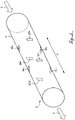
- a transducer setup is shown as part of a device for non-invasive determination of properties of a multiphase current, which is arranged on an electrically conductive, tubular object 2 through which the multiphase current (not shown) flows along the main flow direction S.
- the device has four EMAT transducers 10a, 10b, 10c, 10d positioned upstream along a first object cross section on or near the object wall 4, with one transducer each being arranged at the 12, 3, 6 and 9 o'clock positions is.
- the device further comprises four EMAT transducers 12a, 12b, 12c, 12d positioned downstream along a second object cross-section at or near the object wall 4, one transducer each being located at a 12, 3, 6 and 9 o'clock position is.
- the positions of the upstream positioned transducers 10a, 10b, 10c, 10d are opposite the positions of the downstream positioned transducers 12a, 12b, 12c, 12d only in Longitudinal direction L of the object 2 varies.
- Each two of the upstream positioned transducers 10a, 10b, 10c, 10d and each two of the downstream positioned transducers 12a, 12b, 12c, 12d are arranged on the object 2 diametrically opposite each other.
- the converters 10a, 10b, 10c, 10d, 12a, 12b, 12c, 12d are preferably designed both for sending and for receiving.
- the converters 10a, 10b, 10c, 10d, 12a, 12b, 12c, 12d are designed as phased array converters (see 17 ).
- the multiphase flow comprises a liquid portion 6 and a gaseous portion, which is transported predominantly in the form of large Taylor bubbles 8 and occasionally in the form of small gas bubbles 8 '.
- the phase boundaries between the gaseous component and the liquid component 6 form reflection sources, at which waves coupled into the multi-phase current can be reflected.
- Smaller gas bubbles 8' can occur not only in the area between two Taylor bubbles 8, but in the entire volume of the liquid portion 6.
- a surge section 18 and a subsequent Taylor bubble section 20 together form a surge cycle 16.
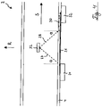
- the Figures 3 to 5 show exemplary embodiments in which, in order to determine the speed of the liquid portion, signals resulting from a wave 28 reflected by a reflection source 22 in the multiphase flow are evaluated.
- a transmitting transducer 24 arranged on or near the object wall 4 on a first side of the object 2 generates an axially propagating in the object wall 4 Shaft 26 wherein a portion of shaft 26 couples at an angle into the multiphase current.
- the wave 27 coupled into the multiphase current hits the reflection source 22 in the multiphase current.
- the wave 28 reflected on the reflection surface couples into the object wall 4 at the entry angle and generates a wave 30 there in the object wall 4.
- a wave 30 is based on this in the object wall 4 generated wave 30 is received by a receiving transducer 32 .
- the waves 26 in the object wall 4 are Lamb waves.
- FIG. 1 shows an embodiment in which the reflection source 22 has a reflection surface running perpendicularly to the main flow direction S of the multiphase current.
- the reflected wave 28 is coupled into the object wall 4 on the side opposite the transmitting transducer 24, where a receiving transducer 32 receives a corresponding signal.
- Information regarding the speed of the reflection source 22 can be obtained from this signal.
- small reflection sources 22 in the liquid portion 6 of the multiphase flow which can be traced back to smaller gas bubbles 8', oil droplets in the water or water droplets in the oil, for example, move with the liquid portion 6, so that the speed of such reflection sources 22 determines the speed of the liquid portion 6 can be determined.
- Waves are preferably generated periodically and for a specific period of time, and the signals resulting from reflected waves 28 are evaluated. If the reflection source 22 moves in the direction of the main flow direction S of the multiphase current, the time interval between the transmission of the wave 26 and the reception of the signal resulting from the wave 30 increases. Conclusions about the axial speed of the reflection source 22 are drawn from a shift in the temporal position of a signal going back to a specific reflection source 22 .
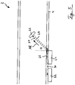
- FIG. 4 shows an embodiment similar 3 with a reflection source 22, the reflection surface of which runs parallel to the main flow direction S of the multiphase current.
- a corresponding signal is received by a receiving transducer 32, which is arranged on the same side as the transmitting transducer 24. If the reflection source 22 moves perpendicularly to the main flow direction S of the multiphase current or in the radial direction R of the tubular object 2, a shift in the temporal Position of the signal returning to the reflection source 22 allows conclusions to be drawn about the radial velocity of the reflection source 22 .
- figure 5 shows an embodiment similar 3 and 4 with a reflection source 22, which has a reflection surface running perpendicular to the main propagation direction AR of the wave 27 coupled into the multiphase current.
- the reflected wave 28 is thrown back by 180° in relation to the wave 27 coupled into the multiphase current.
- the speed of this reflection source 22 has a axial and radial velocity components.
- the signal resulting from the wave 30 coupled into the object wall 4 is received by a receiving transducer 32 on the same side of the object 2 .
- the transmission converter 24 is also designed to receive the signal.
- FIG. 6 shows schematically the course of a propagation time measurement using a wave 27 that is coupled into at least part of the multiphase current.
- a transmitting transducer 24 arranged on or near the object wall 4 on a first side of the object 2 generates a wave 26 that propagates axially in the object wall 4. A part of this Wave 26 couples into the multiphase current.
- the wave 27 coupled into at least part of the multiphase current traverses the multiphase current and couples into the object wall 4 on the opposite side, where it generates a wave 30 in the object wall 4. From the time interval between the transmission of the wave 26 and the reception of the In one embodiment of the invention, the speed of sound of the medium is determined on the basis of the signal resulting from the wave 30 by a receiving transducer 32 arranged on the opposite side.
- the speed of sound of the liquid portion 6 is preferably determined in this case. With knowledge of the sound velocities of the individual components of the liquid portion 6, ie the water and/or the hydrocarbon-containing liquid, the respective portion of the component and thus the water content in the liquid portion itself can be determined.
- a signal (direct wall signal) based on the part of the transmitted wave 26 propagating exclusively in the object wall 4 is used as a reference. This is received by a further receiving transducer 32' on the same side on which the transmitting transducer 24 is arranged.
- the wave 27 traversing the multiphase current has a propagation path extending between a 3 o'clock position and a 9 o'clock position. This runs in particular in a plane running essentially transversely to the direction of gravitation. This increases the probability that the wave 27 will traverse the liquid portion 6 since, in most types of flow, the major part of the gaseous portion collects in an upper area of the object 2 (10 o'clock position to 2 o'clock position).
- a transit time difference between the signals measured upstream and downstream is determined both downstream and upstream, from which the speed of the liquid portion is determined.
- This is realized in a further embodiment according to the invention by an arrangement of two transducers 10b, 10d arranged upstream on opposite sides of the object and two transducers 12b, 12d arranged downstream on two opposite sides of the object.
- a transmitting transducer 24 and a receiving transducer 32 are arranged opposite one another along a first cross section of the object.
- a further transmitting transducer 24' and a further receiving transducer 32' are arranged along a second object cross-section, which is spaced apart from the first object cross-section by the distance d in the longitudinal direction L of the object 2.
- a signal resulting from a wave 28 reflected from a reflection source 22 is observed at the first object cross section. After a certain time, the same or a similar signal is observed at the second object cross-section.
- the speed of the reflection source 22 can be determined from the distance d and the time elapsed between the observations.
- the determination of the flow cross-sectional fraction of the gaseous fraction is explained on the basis of a wave 27 transmitted downstream or upstream and coupled into at least part of the multiphase flow.
- a transmitter transducer 24 arranged in a lowermost position (6 o'clock position) at or near the object wall 4 generates a wave 26 propagating axially in the object wall 4, a part of the wave coupling into the multiphase current at a certain angle.
- the wave 27 coupled into the multiphase flow is either reflected at a horizontal phase boundary 34 running parallel to the main flow direction S of the multiphase flow ( 8 ) or crosses the multiphase current at least once ( 9 ).
- the flow cross-sectional proportion of the gaseous proportion is determined via the height h of the horizontal phase boundary 34 .
- the height h is calculated in particular from the propagation time of a signal resulting from the wave 28 reflected on the reflection surface, which signal is received by a receiving transducer 32' arranged at a lowermost position (6 o'clock position).
- a signal directly wall signal
- resulting from a part of the transmitted wave 26 propagating exclusively in the object wall is used as a reference for calculating the propagation time.
- the wave 27 can cross the multiphase flow and on the opposite side of the object wall 4 couple ( 9 ).
- a resultant signal based on the wave 27 crossing the multiphase current is received by a receiving transducer 32 disposed at an uppermost position (12 o'clock position) on or near the object wall 4 .
- the wave 27 coupled into the multiphase flow from a first side of the object wall 4 can traverse it twice, with the wave coming from the opposite side of the Object wall 4 is reflected (reflected wave 28) and is coupled into the object wall 4 on the first side thereof, where it generates a wave 30' in the object wall 4.
- a signal resulting from this wave 30' is received by the receiving transducer 32'.
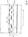
- the signals repeatedly recorded by the receiving transducers 32, 32' over a longer period of time are shown according to their propagation time ⁇ t.
- the receiving transducer 32' arranged at the lowest position (6 o'clock position) receives on the one hand the direct wall signal 36, which is used in particular as a reference for calculating the propagation times ⁇ t.
- the receiving transducer 32 arranged at the top position (12 o'clock position) only receives a signal when the flow cross section along a propagation path of the wave 27 coupled into the multiphase flow is completely occupied by the liquid portion 6 of the multiphase flow. These signals are shown along line RX1.
- the receiving transducer 32' arranged at the 6 o'clock position also receives a corresponding signal, which is characterized in particular by the maximum possible propagation time ⁇ t.
- signals are shown along line RX2.
- Signals reflected at horizontal phase boundary 34 received by receive transducer 32' located at the 6 o'clock position are between lines RX1 and RX2. It can be seen that, over time T, transmission areas 38, which point in particular to a surge section 18, and reflection areas 40, which point in particular to a Taylor bubble section 20 indicate cyclically follow one another.
- the measured transit times ⁇ t at a specific time T provide information about the height of the horizontal phase boundary and thus about the flow cross-section share of the gaseous part.
- a further method for determining the flow cross-sectional proportion of the gaseous proportion on the basis of a part of a wave transmitted downstream or upstream that propagates exclusively in the object wall is described below using 11 and 12 described.
- FIG. 11 shows a tubular object with a full-circumferential transmitting transducer 42 arranged along a first cross-section of the object on or near the object wall 4, which transmits a wave upstream along its full circumference into the object wall, with the signals resulting from the part of this wave propagating exclusively in the object wall 4 at a second object cross section spaced apart from the first object cross section in the longitudinal direction L of the object 2 can be received at different circumferential positions by eight receiving transducers 44a to 44h arranged along the circumference.
- the wave generated in the object wall 4 couples into the multiphase current to different degrees. How out 12 becomes clear, the weakening of the amplitude allows conclusions to be drawn about the composition of the part of the multiphase current adjoining the object wall 4 .
- 12 shows the progression of the amplitudes the time T of signals resulting from the part of the transmitted wave propagating exclusively in the object wall 4, which were received at different circumferential positions of the object.
- Diagram e) shows the evaluation of the signals received at a 6 o'clock position. The amplitude of the direct signal is relatively small since a large part of the wave is coupled into the part of the multiphase current located behind the part of the object wall 4 .
- a part of a signal for determining the water content in the liquid part 6 of the multiphase stream which is transmitted by a transmitter transducer 24 arranged in a 6 o'clock position, is shown, propagating exclusively in the object wall 4.
- the signal received by the receiving transducer 32 is in accordance with its amplitude in the in 14 shown plotted over time.
- the measurement curve A1 corresponds to a water content of 0%, the measurement curve A2 to a water content of 20% and the measurement curve A3 to a water content of 100%.
- the proportion of the flow rate of the gaseous portion of the total flow phase was 33% for all three measurements.
- a flexible carrier 46 which is designed in particular as a printed circuit board, with four transducers 48 to be arranged along an object cross section.
- the transducers 48 can thus be optimally positioned on the outer contour of the object wall 4, with the positioning of the transducers in relation to one another (12 o'clock, 3 o'clock, 6 o'clock and 9 o'clock position) is specified, which makes the installation of the device more practical.
- Converter 50 also has eight converters 48 that essentially cover the object 2 in the circumferential direction in their entirety.
- 17 1 schematically shows a structure of a converter 48 designed as a phased array converter, comprising two mutually offset coils 52, 54 which are spatially offset from one another by ⁇ /4, where ⁇ is the wavelength of the wave 26 generated in the object wall 4.
- the spatial offset in combination with a corresponding phase offset of the excitation currents of ⁇ 90° allows the wave 26 in the object wall 4 (not shown)—depending on the sign of the phase offset—to be sent in direction W or in direction W′.
Landscapes
- Physics & Mathematics (AREA)
- General Physics & Mathematics (AREA)
- Chemical & Material Sciences (AREA)
- Health & Medical Sciences (AREA)
- Life Sciences & Earth Sciences (AREA)
- Analytical Chemistry (AREA)
- Biochemistry (AREA)
- General Health & Medical Sciences (AREA)
- Immunology (AREA)
- Pathology (AREA)
- Acoustics & Sound (AREA)
- Engineering & Computer Science (AREA)
- Electromagnetism (AREA)
- Fluid Mechanics (AREA)
- Chemical Kinetics & Catalysis (AREA)
- General Chemical & Material Sciences (AREA)
- Oil, Petroleum & Natural Gas (AREA)
- Food Science & Technology (AREA)
- Medicinal Chemistry (AREA)
- Multimedia (AREA)
- Aviation & Aerospace Engineering (AREA)
- Investigating Or Analyzing Materials By The Use Of Ultrasonic Waves (AREA)
- Measuring Volume Flow (AREA)
- Investigating Or Analyzing Materials By The Use Of Electric Means (AREA)
Claims (33)
- Procédé de détermination non invasive de propriétés d'un flux polyphasique qui comprend une fraction liquide (6), comprenant notamment de l'eau et/ou un liquide contenant des hydrocarbures, et une fraction gazeuse et qui s'écoule à travers un objet électriquement conducteur (2), de préférence un tube ou une canalisation, les propriétés du flux polyphasique comprenant notamment au moins la vitesse de la fraction gazeuse, la vitesse de la fraction liquide (6), la proportion de la fraction gazeuse au niveau d'une section transversale d'écoulement et/ou la teneur en eau dans la fraction liquide (6), dans le procédé- à l'aide d'une configuration unique comprenant une pluralité de transducteurs EMAT (10a, 10b, 10c, 10d, 12a, 12b, 12c, 12d, 24, 24', 32, 32', 42, 44a, 44b, 44c, 44d, 44e, 44f, 44g, 44h, 48, 50), notamment selon la revendication de dispositif 24,- au moins deux signaux étant spatialement corrélés entre eux pour déterminer la vitesse de la fraction gazeuse,- au moins un signal obtenu sur la base d'une onde (28) réfléchie par une source de réflexion (22) située dans le flux polyphasique, et/ou au moins un signal obtenu sur la base d'une onde (27) émise vers l'amont et injectée par couplage au moins dans une partie du flux polyphasique et au moins un signal obtenu sur la base d'une onde (27) émise vers l'aval et injectée par couplage dans au moins une partie du flux polyphasique, étant évalués pour déterminer la vitesse de la fraction liquide (6), et- au moins un signal obtenu sur la base d'une onde (27) émise vers l'aval ou vers l'amont et injectée par couplage dans au moins une partie du flux polyphasique, et/ou au moins un signal obtenu sur la base d'une partie, se propageant exclusivement dans la paroi d'objet (4), d'une onde (26) émise vers l'aval ou vers l'amont, étant évalués pour déterminer la proportion de la fraction gazeuse au niveau d'une section transversale d'écoulement.
- Procédé selon la revendication 1, caractérisé en ce qu'au moins le débit de la fraction liquide (6) et/ou le débit de la fraction gazeuse sont déterminés à partir d'au moins deux propriétés du flux polyphasique.
- Procédé selon l'une des revendications précédentes, caractérisé en ce qu'au moins un signal obtenu sur la base d'une partie, se propageant exclusivement dans la paroi d'objet (4), d'une onde (26) émise vers l'aval ou vers l'amont, et/ou au moins un signal obtenu sur la base d'une onde (27) émise vers l'amont ou vers l'aval et injectée par couplage dans au moins une partie du flux polyphasé, sont évalués pour déterminer la teneur en eau dans la fraction liquide (6) .
- Procédé selon la revendication 3, caractérisé en ce qu'au moins un signal obtenu sur la base d'une onde (27) émise vers l'amont ou vers l'aval et injectée par couplage dans au moins une partie du flux polyphasique et un signal obtenu sur la base d'une autre onde (27) émise dans l'autre direction respective (vers l'amont ou vers l'aval) et injectée par couplage dans au moins une partie du flux polyphasique sont évalués pour déterminer la teneur en eau dans la fraction liquide (6) .
- Procédé selon l'une des revendications précédentes, caractérisé en ce que, notamment pour déterminer la proportion de la fraction gazeuse au niveau d'une section transversale d'écoulement et/ou pour déterminer la teneur en eau de la fraction liquide (6), l'au moins un signal obtenu sur la base d'une partie, se propageant exclusivement dans la paroi d'objet (4), d'une onde (26) émise à une première position en amont ou en aval est reçu à une deuxième position distante de la première position dans la direction longitudinale (L) de l'objet (2), la composition de la partie, adjacente à la paroi d'objet (4), du flux polyphasique étant déterminée sur la base de l'amplitude (A) du signal.
- Procédé selon l'une des revendications précédentes, caractérisé en ce que, dans le cas d'un objet (2) s'étendant horizontalement, au moins une partie des ondes (27, 28), émises vers l'amont et/ou vers l'aval et injectées par couplage dans au moins partie du flux polyphasique, ont chacune au moins un chemin de propagation qui s'étend entre une position à 3 heures et une position à 9 heures.
- Procédé selon l'une des revendications précédentes, caractérisé en ce que, notamment pour déterminer la vitesse de la fraction gazeuse, au moins deux signaux situés à deux positions distantes l'une de l'autre dans la direction longitudinale (L) de l'objet (2) sont corrélés entre eux.
- Procédé selon l'une des revendications précédentes, caractérisé en ce qu'un décalage en fréquence du signal, obtenu sur la base d'une onde (28) réfléchie par une source de réflexion située dans le flux polyphasique, est évalué notamment pour déterminer la vitesse de la fraction liquide (6) et/ou la vitesse de la fraction gazeuse.
- Procédé selon l'une des revendications précédentes, caractérisé en ce que des ondes (26) sont générées périodiquement et les signaux obtenus sur la base des ondes réfléchies (28) sont évalués notamment pour déterminer la vitesse de la fraction liquide (6), au moins la vitesse d'une source de réflexion déterminée (22) étant déterminée à partir d'un décalage de la position temporelle d'au moins un signal remontant vers la source de réflexion (22).
- Procédé selon l'une des revendications précédentes, caractérisé en ce qu'au moins un signal, obtenu sur la base d'une onde réfléchie (28) par une surface de réflexion qui s'étend perpendiculairement ou parallèlement à la direction d'écoulement principale (S) du flux polyphasique ou perpendiculairement à la direction de propagation principale (AR) de l'onde (27) injectée par couplage dans le flux polyphasique, est évalué notamment pour déterminer la vitesse de la fraction liquide (6).
- Procédé selon l'une des revendications précédentes, caractérisé en ce que la différence de temps de propagation entre l'au moins un signal, obtenu sur la base d'une onde (27) émise vers l'amont et injectée par couplage dans au moins une partie du flux polyphasique, et l'au moins un signal, obtenu sur la base d'une onde (27) émise vers l'aval et injectée par couplage dans au moins une partie du flux polyphasique, est évaluée notamment pour déterminer la vitesse de la fraction liquide (6).
- Procédé selon l'une des revendications précédentes, caractérisé en ce qu'au moins un signal, obtenu sur la base d'une onde (28) qui est réfléchie par une source de réflexion (22) située dans le flux polyphasique et qui est obtenue au moins partiellement à partir d'une onde (27) émise vers l'aval ou vers l'amont à première position et injectée par couplage dans au moins une partie du flux polyphasique, est reçu à une deuxième position distante de la première position dans la direction longitudinale (L) de l'objet (2) notamment pour déterminer la proportion de la fraction gazeuse au niveau d'une section transversale d'écoulement.
- Procédé selon la revendication 12, caractérisé en ce que l'onde (26), émise vers l'aval ou vers l'amont à une première position, est émise depuis une position circonférentielle la plus basse (position à 6 heures) et en ce que le signal, obtenu sur la base de l'onde (28) réfléchie par la source de réflexion (22) située dans le flux polyphasique, est reçu à une position circonférentielle la plus basse (position à 6 heures).
- Procédé selon l'une des revendications précédentes, caractérisé en ce qu'au moins un signal, obtenu sur la base d'une onde (27) transmise à travers au moins une partie du flux polyphasique, est évalué notamment pour déterminer la proportion de la fraction gazeuse au niveau d'une section transversale d'écoulement, l'onde transmise (27) étant obtenue au moins en partie à partir de l'onde (26) émise vers l'aval ou vers l'amont dans le flux polyphasique.
- Procédé selon l'une des revendications précédentes, caractérisé en ce qu'au moins un signal, obtenu à partir d'une onde (28) transmise deux fois à travers au moins une partie du flux polyphasique est évalué notamment pour déterminer la proportion de la fraction gazeuse au niveau d'une section transversale d'écoulement, l'onde transmise deux fois (28) étant obtenue au moins en partie à partir de l'onde (26) émise vers l'aval ou vers l'amont dans le flux polyphasique.
- Procédé selon l'une des revendications précédentes, caractérisé en ce que l'au moins une onde émise vers l'amont ou vers l'aval (26) est émise le long d'un première section transversale d'objet sur toute la circonférence jusque dans la paroi d'objet (4) et les signaux, obtenus sur la base de la partie de cette onde (26) qui se propage exclusivement dans la paroi d'objet (4) sont reçus en au moins deux positions circonférentielles différentes au niveau d'une deuxième section transversale d'objet distante de la première section transversale d'objet dans la direction longitudinale (L) de l'objet (2), notamment pour déterminer la proportion de la fraction gazeuse au niveau d'une section transversale d'écoulement.
- Procédé selon l'une des revendications précédentes, caractérisé en ce qu'au moins une des méthodes de mesure est associée à des paramètres de configuration déterminés en fonction desquels les transducteurs (10a, 10b, 10c, 10d, 12a, 12b, 12c, 12d, 24, 24', 32, 32', 42, 44a, 44b, 44c, 44d, 44e, 44f, 44g, 44h, 48, 50) nécessaires à la méthode de mesure sont commandés.
- Procédé selon l'une des revendications précédentes, caractérisé en ce qu'au moins un des transducteurs (10a, 10b, 10c, 10d, 12a, 12b, 12c, 12d, 24, 24', 32, 32', 42, 44a, 44b, 44c, 44d, 44e, 44f, 44g, 44h, 48, 50) est utilisé aussi bien comme émetteur que comme récepteur.
- Procédé selon l'une des revendications précédentes, caractérisé en ce qu'au moins un des transducteurs (10a, 10b, 10c, 10d, 12a, 12b, 12c, 12d, 24, 24', 32, 32', 42, 44a, 44b, 44c, 44d, 44e, 44f, 44g, 44h, 48, 50) émet en étant dirigé vers l'amont et/ou vers l'aval.
- Procédé selon l'une des revendications précédentes, caractérisé en ce qu'au moins un des transducteurs (10a, 10b, 10c, 10d, 12a, 12b, 12c, 12d, 24, 24', 32, 32', 42, 44a, 44b, 44c, 44d, 44e, 44f, 44g, 44h, 48, 50) génère des ondes Lamb dans la paroi d'objet (4).
- Procédé selon l'une des revendications précédentes, caractérisé en ce que, en ce qui concerne au moins une propriété du flux polyphasique, la méthode de mesure déterminant celle-ci est sélectionnée en fonction du rapport fraction gazeuse à fraction liquide (6) du flux polyphasique, en notamment en fonction du débit de la fraction liquide (6) et/ou du débit de la fraction gazeuse.
- Procédé selon l'une des revendications précédentes, caractérisé en ce qu'une pluralité de mesures individuelles sont réalisées et évaluées pour déterminer au moins une des propriétés pour au moins une méthode de mesure, notamment de préférence une valeur moyenne et/ou une valeur maximale étant déterminée.
- Procédé selon l'une des revendications précédentes, caractérisé en ce qu'une fréquence de répétition d'impulsions d'au moins 200 Hz, de préférence d'au moins 400 Hz, de manière particulièrement préférée d'au moins 800 Hz, et au maximum de 5 kHz est utilisée pour au moins une méthode de mesure.
- Dispositif de détermination non invasive de propriétés d'un flux polyphasique qui comprend une fraction liquide (6), comprenant notamment de l'eau et/ou un liquide contenant des hydrocarbures, et une fraction gazeuse et qui s'écoule à travers un objet électriquement conducteur (2), de préférence un tube ou une canalisation, ledit dispositif comprenant- au moins quatre transducteurs EMAT (10a, 10b, 10c, 10d, 24, 24', 32, 32', 48) destinés à être positionnés en amont le long d'une première section transversale d'objet au niveau ou à proximité de la paroi d'objet (4) et- au moins quatre transducteurs EMAT (12a, 12b, 12c, 12d, 24, 24', 32, 32', 48) destinés à être positionnés en aval le long d'une deuxième section transversale d'objet au niveau ou à proximité de la paroi d'objet (4),- deux des transducteurs (10a, 10b, 10c, 10d, 24, 24', 32, 32', 48) destinés être positionnés en amont et deux des transducteurs (12a, 12b, 12c, 12d, 24, 24', 32, 32', 48) destinés à être positionnés en aval étant à chaque fois disposés face à face sur l'objet (2) et- les positions des transducteurs (10a, 10b, 10c, 10d, 24, 24', 32, 32', 48) destinés à être positionnés en amont par rapport aux positions des transducteurs (12a, 12b, 12c, 12d, 24, 24', 32, 32', 48) destinés à être positionnés en aval ne variant que dans la direction longitudinale (L) de l'objet (2),- ledit dispositif comprenant en outre une unité de commande qui commande les transducteurs (10a, 10b, 10c, 10d, 12a, 12b, 12c, 12d, 24, 24', 32, 32', 48) nécessaires à la méthode de mesure respective, notamment à l'aide de paramètres de configuration déterminés, et- une unité d'évaluation qui évalue les données générées à partir des signaux reçus,caractérisé en ce que l'unité de commande et l'unité d'évaluation sont conçues pour réaliser les étapes du procédé selon l'une des revendications 1 à 23.
- Dispositif selon la revendication 24, caractérisé en ce qu'au moins les transducteurs EMAT (10a, 10b, 10c, 10d, 12a, 12b, 12c, 12d, 24, 24', 32, 32', 48) disposés le long d'une des sections transversales d'objet recouvrent au moins sensiblement intégralement l'objet (2) dans la direction circonférentielle.
- Dispositif selon la revendication 24 ou 25, caractérisé en ce que le dispositif comprend au moins six, de préférence au moins huit, notamment au maximum 40, transducteurs EMAT (44a, 44b, 44c, 44d, 44e, 44f, 44g, 44h, 48), destinés à être positionnés au niveau ou à proximité de la paroi d'objet (4), le long d'une première section transversale d'objet et/ou une deuxième section transversale d'objet.
- Dispositif selon l'une des revendications 24 à 26, caractérisé en ce que le dispositif comprend en outre au moins un transducteur EMAT (42, 50) qui englobe l'objet (2) sensiblement sur toute la circonférence.
- Dispositif selon l'une des revendications 24 à 27, caractérisé en ce que le dispositif comprend au moins deux transducteurs EMAT (42, 50) de conception circonférentielle, un premier transducteur EMAT (42, 50) de conception circonférentielle étant disposé en amont des au moins quatre transducteurs EMAT (10a, 10b, 10c, 10d, 24, 24', 32, 32', 48) destinés à être positionnés en amont le long d'une première section transversale d'objet au niveau ou à proximité de la paroi d'objet (4) et un deuxième transducteur EMAT (42, 50) de conception circonférentielle étant disposé en aval des au moins quatre transducteurs EMAT (12a, 12b, 12c, 12d, 24, 24', 32, 32', 48) destinés à être positionnés en aval le long d'une deuxième section transversale d'objet au niveau ou à proximité de la paroi d'objet (4).
- Dispositif selon l'une des revendications 24 à 28, caractérisé en ce qu'au moins un des transducteurs (10a, 10b, 10c, 10d, 12a, 12b, 12c, 12d, 24, 24', 32, 32', 42, 44a, 44b, 44c, 44d, 44e, 44f, 44g, 44h, 48, 50) est conçu comme un transducteur multiéléments comprenant au moins deux bobines (53, 54) décalées spatialement l'une de l'autre.
- Dispositif selon l'une des revendications 24 à 29, caractérisé en ce que dans la direction radiale (R) de l'objet (2), au-dessus d'au moins un premier transducteur (10a, 10b, 10c, 10d, 12a, 12b, 12c, 12d, 24, 24', 32, 32', 42, 44a, 44b, 44c, 44d, 44e, 44f, 44g, 44h, 48, 50) qui est conçu pour générer des ondes ultrasonores (26) d'une première longueur d'onde (λ), est disposé au moins un autre transducteur (10a, 10b, 10c, 10d, 12a, 12b, 12c, 12d, 24, 24', 32, 32', 42, 44a, 44b, 44c, 44d, 44e, 44f, 44g, 44h, 48, 50) qui est conçu pour générer des ondes ultrasonores (26) d'une autre longueur d'onde (λ).
- Dispositif selon l'une des revendications 24 à 30, caractérisé en ce que le dispositif comporte au moins un support souple (46) dans lequel sont disposés les transducteurs (10a, 10b, 10c, 10d, 24, 24', 32, 32', 48) destinés à être positionnés en amont et/ou les transducteurs (12a, 12b, 12c, 12d, 24, 24', 32, 32', 48) destinés à être positionnés en aval et/ou les transducteurs EMAT (42, 50) de conception circonférentielle.
- Dispositif selon la revendication 31, caractérisé en ce que le support souple (46) est réalisé sous la forme d'un circuit imprimé souple et les bobines (52, 54) d'au moins un des transducteurs (10a, 10b, 10c, 10d, 12a, 12b, 12c, 12d, 24, 24', 32, 32', 42, 44a, 44b, 44c, 44d, 44e, 44f, 44g, 44h, 48, 50) sont imprimés sur un circuit imprimé souple, en particulier dans l'image de cuivre.
- Dispositif selon l'une des revendications 24 à 32, caractérisé en ce que les bobines (52, 54) d'au moins un des transducteurs (10a, 10b, 10c, 10d, 12a, 12b, 12c, 12d, 24, 24', 32, 32', 42, 44a, 44b, 44c, 44d, 44e, 44f, 44g, 44h, 48, 50) sont disposées les unes au-dessus des autres dans la direction radiale (R) de l'objet (2).
Applications Claiming Priority (2)
| Application Number | Priority Date | Filing Date | Title |
|---|---|---|---|
| DE102018125923.9A DE102018125923A1 (de) | 2018-10-18 | 2018-10-18 | Verfahren und Vorrichtung zur nichtinvasiven Bestimmung von Eigenschaften eines Multiphasenstroms |
| PCT/EP2019/077533 WO2020078833A2 (fr) | 2018-10-18 | 2019-10-10 | Procédé et dispositif de détermination non invasive de caractéristiques d'un courant polyphasé |
Publications (2)
| Publication Number | Publication Date |
|---|---|
| EP3867636A2 EP3867636A2 (fr) | 2021-08-25 |
| EP3867636B1 true EP3867636B1 (fr) | 2022-11-23 |
Family
ID=68542582
Family Applications (1)
| Application Number | Title | Priority Date | Filing Date |
|---|---|---|---|
| EP19802076.0A Active EP3867636B1 (fr) | 2018-10-18 | 2019-10-10 | Procédé et dispositif de détermination non invasive de caractéristiques d'un courant polyphasé |
Country Status (5)
| Country | Link |
|---|---|
| US (1) | US20210381866A1 (fr) |
| EP (1) | EP3867636B1 (fr) |
| CA (1) | CA3116799C (fr) |
| DE (1) | DE102018125923A1 (fr) |
| WO (1) | WO2020078833A2 (fr) |
Families Citing this family (2)
| Publication number | Priority date | Publication date | Assignee | Title |
|---|---|---|---|---|
| FR3118178B1 (fr) * | 2020-12-23 | 2023-07-21 | Buerkert Werke Gmbh & Co Kg | Moyen de mesure de fluide |
| JP7254232B1 (ja) | 2022-04-22 | 2023-04-07 | 株式会社日立パワーソリューションズ | アレイ型超音波送受信装置およびパルス信号生成部の駆動開始時間調整方法 |
Family Cites Families (13)
| Publication number | Priority date | Publication date | Assignee | Title |
|---|---|---|---|---|
| US6386018B1 (en) * | 1996-03-11 | 2002-05-14 | Daniel Industries, Inc. | Ultrasonic 2-phase flow apparatus and stratified level detector |
| WO1997039314A1 (fr) * | 1996-04-16 | 1997-10-23 | Mobil Oil Corporation | Procede de controle d'un ecoulement de fluide a trois phases dans des conduits tubulaires |
| US6065350A (en) * | 1998-07-10 | 2000-05-23 | Panametrics, Inc. | Flow measurement system with guided signal launched in lowest mode |
| JP2000097742A (ja) * | 1998-09-25 | 2000-04-07 | Tokyo Electric Power Co Inc:The | ドップラ式超音波流量計 |
| GB9823675D0 (en) * | 1998-10-30 | 1998-12-23 | Schlumberger Ltd | Flowmeter |
| WO2002077635A2 (fr) * | 2001-03-23 | 2002-10-03 | Joseph Baumoel | Procede de determination de quantites relatives de constituants dans un ecoulement polyphasique |
| US6568271B2 (en) * | 2001-05-08 | 2003-05-27 | Halliburton Energy Services, Inc. | Guided acoustic wave sensor for pipeline build-up monitoring and characterization |
| DE102009022492A1 (de) * | 2009-05-25 | 2010-12-02 | Sensaction Ag | Vorrichtung zur Bestimmung der Eigenschaften eines Mediums in Form einer Flüssigkeit oder eines weichen Materials |
| BR112012015646B1 (pt) * | 2009-12-22 | 2021-02-02 | Xsens As | aparelho de medição |
| DE102012019217B4 (de) * | 2012-10-01 | 2014-08-07 | Rosen Swiss Ag | Akustischer Durchflussmesser und Verfahren zur Bestimmung des Flusses in einem Objekt |
| EP2913641B1 (fr) * | 2014-02-28 | 2019-07-31 | Yokogawa Electric Corporation | Débitmètre multiphase |
| US10222247B2 (en) * | 2016-07-07 | 2019-03-05 | Joseph Baumoel | Multiphase ultrasonic flow meter |
| WO2018175503A2 (fr) * | 2017-03-20 | 2018-09-27 | Los Alamos National Security, Llc | Mesure simultanée en temps réel de composition, de flux, d'atténuation, de densité et d'épaisseur de paroi de tuyau dans des fluides polyphasés |
-
2018
- 2018-10-18 DE DE102018125923.9A patent/DE102018125923A1/de not_active Withdrawn
-
2019
- 2019-10-10 CA CA3116799A patent/CA3116799C/fr active Active
- 2019-10-10 WO PCT/EP2019/077533 patent/WO2020078833A2/fr active Search and Examination
- 2019-10-10 EP EP19802076.0A patent/EP3867636B1/fr active Active
- 2019-10-10 US US17/285,934 patent/US20210381866A1/en active Pending
Also Published As
| Publication number | Publication date |
|---|---|
| CA3116799C (fr) | 2024-02-13 |
| WO2020078833A3 (fr) | 2020-06-11 |
| CA3116799A1 (fr) | 2020-04-23 |
| WO2020078833A2 (fr) | 2020-04-23 |
| DE102018125923A1 (de) | 2020-04-23 |
| US20210381866A1 (en) | 2021-12-09 |
| EP3867636A2 (fr) | 2021-08-25 |
Similar Documents
| Publication | Publication Date | Title |
|---|---|---|
| EP3267159B1 (fr) | Dispositif de mesure des ultrasons et procédé de mesure de la vitesse d'écoulement d'un liquide dans un pipeline | |
| EP2291619A1 (fr) | Procédé et système de mesure pour déterminer et/ou surveiller le débit d un milieu à mesurer à travers un tube de mesure | |
| DE19933473B4 (de) | Verfahren zum Messen einer horizontalen mittleren Strömungsgeschwindigkeit eines Flusses | |
| EP3577427B1 (fr) | Compteur à ultrasons et procédé d'acquisition d'une grandeur de débit | |
| DE19722274A1 (de) | Verfahren zur Messung von Dichte und Massenstrom | |
| EP3867636B1 (fr) | Procédé et dispositif de détermination non invasive de caractéristiques d'un courant polyphasé | |
| DE4430223A1 (de) | Ultraschallströmungs-Meßverfahren und Vorrichtung zur Durchführung des Verfahrens | |
| DE102009048646A1 (de) | Verfahren zur Bestimmung der Strömungsgeschwindigkeit eines Mediums und Vorrichtung zur Bestimmung der Strömungsgeschwindigkeit eines Mediums | |
| EP2440888B1 (fr) | Procédé de mesure d'un mesurande | |
| EP2872857A1 (fr) | Débitmètre à ultrasons | |
| DE102014115203B3 (de) | Verfahren und Anordnung zur Ultraschall-Clamp-on-Durchflussmessung und Schaltungsanordnung zur Steuerung einer Ultraschall-Clamp-on-Durchflussmessung | |
| DE2828937C2 (fr) | ||
| EP3894799B1 (fr) | Agencement de transducteurs ultrasonores d'un appareil de mesure de debit a ultrasons a pinces, et appareil de mesure de debit a ultrasons a pinces et procede de mise en marche de l'appareil de mesure de debit a ultrasons a pinces | |
| DE102015102200A1 (de) | Verfahren zur Bestimmung von Eigenschaften eines Mediums und Vorrichtung zur Bestimmung von Eigenschaften eines Mediums | |
| DE19934212B4 (de) | Verfahren und Vorrichtung zum Messen der Strömungsgeschwindigkeit eines Fluidstromes | |
| EP3405780B1 (fr) | Procédé de détermination de caractéristiques d'un milieu et dispositif pour la détermination de caractéristiques d'un milieu | |
| DE19605164C2 (de) | Ultraschall-Strömungsmeßgerät | |
| WO2020120091A1 (fr) | Ensemble de transducteurs ultrasonores d'un point de mesure de débit à ultrasons du type "clamp-on", ainsi que point de mesure de débit à ultrasons du type "clamp-on" et procédé de mise en service dudit point de mesure de débit à ultrasons du type "clamp-on" | |
| DE19633558A1 (de) | Ultraschall-Durchflußmeßverfahren | |
| EP3855134B1 (fr) | Dispositif de mesure du débit d'écoulement d'un fluide | |
| DE19957905B4 (de) | Verfahren und Vorrichtung zur zerstörungsfreien Prüfung von Schweißnähten mittels Ultraschall | |
| DE102015106695A1 (de) | Verfahren und Vorrichtung zur Durchflussmessung | |
| WO2005031369A2 (fr) | Capteur a ultrasons, et procede pour mesurer des vitesses d'ecoulement | |
| EP2511673A1 (fr) | Procédé de mesure de la quantité de débit selon le principe de la différence du temps de parcours des ultrasons | |
| DE2813754A1 (de) | Verfahren und vorrichtung zum erkennen der stroemung eines materials durch wellenenergiestrahlung |
Legal Events
| Date | Code | Title | Description |
|---|---|---|---|
| STAA | Information on the status of an ep patent application or granted ep patent |
Free format text: STATUS: UNKNOWN |
|
| STAA | Information on the status of an ep patent application or granted ep patent |
Free format text: STATUS: THE INTERNATIONAL PUBLICATION HAS BEEN MADE |
|
| STAA | Information on the status of an ep patent application or granted ep patent |
Free format text: STATUS: THE INTERNATIONAL PUBLICATION HAS BEEN MADE |
|
| PUAI | Public reference made under article 153(3) epc to a published international application that has entered the european phase |
Free format text: ORIGINAL CODE: 0009012 |
|
| STAA | Information on the status of an ep patent application or granted ep patent |
Free format text: STATUS: REQUEST FOR EXAMINATION WAS MADE |
|
| 17P | Request for examination filed |
Effective date: 20210514 |
|
| AK | Designated contracting states |
Kind code of ref document: A2 Designated state(s): AL AT BE BG CH CY CZ DE DK EE ES FI FR GB GR HR HU IE IS IT LI LT LU LV MC MK MT NL NO PL PT RO RS SE SI SK SM TR |
|
| DAV | Request for validation of the european patent (deleted) | ||
| DAX | Request for extension of the european patent (deleted) | ||
| GRAP | Despatch of communication of intention to grant a patent |
Free format text: ORIGINAL CODE: EPIDOSNIGR1 |
|
| STAA | Information on the status of an ep patent application or granted ep patent |
Free format text: STATUS: GRANT OF PATENT IS INTENDED |
|
| INTG | Intention to grant announced |
Effective date: 20220510 |
|
| GRAS | Grant fee paid |
Free format text: ORIGINAL CODE: EPIDOSNIGR3 |
|
| GRAA | (expected) grant |
Free format text: ORIGINAL CODE: 0009210 |
|
| STAA | Information on the status of an ep patent application or granted ep patent |
Free format text: STATUS: THE PATENT HAS BEEN GRANTED |
|
| AK | Designated contracting states |
Kind code of ref document: B1 Designated state(s): AL AT BE BG CH CY CZ DE DK EE ES FI FR GB GR HR HU IE IS IT LI LT LU LV MC MK MT NL NO PL PT RO RS SE SI SK SM TR |
|
| REG | Reference to a national code |
Ref country code: GB Ref legal event code: FG4D Free format text: NOT ENGLISH |
|
| REG | Reference to a national code |
Ref country code: CH Ref legal event code: EP |
|
| REG | Reference to a national code |
Ref country code: AT Ref legal event code: REF Ref document number: 1533435 Country of ref document: AT Kind code of ref document: T Effective date: 20221215 Ref country code: DE Ref legal event code: R096 Ref document number: 502019006379 Country of ref document: DE |
|
| REG | Reference to a national code |
Ref country code: IE Ref legal event code: FG4D Free format text: LANGUAGE OF EP DOCUMENT: GERMAN |
|
| REG | Reference to a national code |
Ref country code: NL Ref legal event code: FP |
|
| REG | Reference to a national code |
Ref country code: LT Ref legal event code: MG9D |
|
| REG | Reference to a national code |
Ref country code: NO Ref legal event code: T2 Effective date: 20221123 |
|
| PG25 | Lapsed in a contracting state [announced via postgrant information from national office to epo] |
Ref country code: SE Free format text: LAPSE BECAUSE OF FAILURE TO SUBMIT A TRANSLATION OF THE DESCRIPTION OR TO PAY THE FEE WITHIN THE PRESCRIBED TIME-LIMIT Effective date: 20221123 Ref country code: PT Free format text: LAPSE BECAUSE OF FAILURE TO SUBMIT A TRANSLATION OF THE DESCRIPTION OR TO PAY THE FEE WITHIN THE PRESCRIBED TIME-LIMIT Effective date: 20230323 Ref country code: LT Free format text: LAPSE BECAUSE OF FAILURE TO SUBMIT A TRANSLATION OF THE DESCRIPTION OR TO PAY THE FEE WITHIN THE PRESCRIBED TIME-LIMIT Effective date: 20221123 Ref country code: FI Free format text: LAPSE BECAUSE OF FAILURE TO SUBMIT A TRANSLATION OF THE DESCRIPTION OR TO PAY THE FEE WITHIN THE PRESCRIBED TIME-LIMIT Effective date: 20221123 Ref country code: ES Free format text: LAPSE BECAUSE OF FAILURE TO SUBMIT A TRANSLATION OF THE DESCRIPTION OR TO PAY THE FEE WITHIN THE PRESCRIBED TIME-LIMIT Effective date: 20221123 |
|
| PG25 | Lapsed in a contracting state [announced via postgrant information from national office to epo] |
Ref country code: RS Free format text: LAPSE BECAUSE OF FAILURE TO SUBMIT A TRANSLATION OF THE DESCRIPTION OR TO PAY THE FEE WITHIN THE PRESCRIBED TIME-LIMIT Effective date: 20221123 Ref country code: PL Free format text: LAPSE BECAUSE OF FAILURE TO SUBMIT A TRANSLATION OF THE DESCRIPTION OR TO PAY THE FEE WITHIN THE PRESCRIBED TIME-LIMIT Effective date: 20221123 Ref country code: LV Free format text: LAPSE BECAUSE OF FAILURE TO SUBMIT A TRANSLATION OF THE DESCRIPTION OR TO PAY THE FEE WITHIN THE PRESCRIBED TIME-LIMIT Effective date: 20221123 Ref country code: IS Free format text: LAPSE BECAUSE OF FAILURE TO SUBMIT A TRANSLATION OF THE DESCRIPTION OR TO PAY THE FEE WITHIN THE PRESCRIBED TIME-LIMIT Effective date: 20230323 Ref country code: HR Free format text: LAPSE BECAUSE OF FAILURE TO SUBMIT A TRANSLATION OF THE DESCRIPTION OR TO PAY THE FEE WITHIN THE PRESCRIBED TIME-LIMIT Effective date: 20221123 Ref country code: GR Free format text: LAPSE BECAUSE OF FAILURE TO SUBMIT A TRANSLATION OF THE DESCRIPTION OR TO PAY THE FEE WITHIN THE PRESCRIBED TIME-LIMIT Effective date: 20230224 |
|
| PG25 | Lapsed in a contracting state [announced via postgrant information from national office to epo] |
Ref country code: SM Free format text: LAPSE BECAUSE OF FAILURE TO SUBMIT A TRANSLATION OF THE DESCRIPTION OR TO PAY THE FEE WITHIN THE PRESCRIBED TIME-LIMIT Effective date: 20221123 Ref country code: RO Free format text: LAPSE BECAUSE OF FAILURE TO SUBMIT A TRANSLATION OF THE DESCRIPTION OR TO PAY THE FEE WITHIN THE PRESCRIBED TIME-LIMIT Effective date: 20221123 Ref country code: EE Free format text: LAPSE BECAUSE OF FAILURE TO SUBMIT A TRANSLATION OF THE DESCRIPTION OR TO PAY THE FEE WITHIN THE PRESCRIBED TIME-LIMIT Effective date: 20221123 Ref country code: DK Free format text: LAPSE BECAUSE OF FAILURE TO SUBMIT A TRANSLATION OF THE DESCRIPTION OR TO PAY THE FEE WITHIN THE PRESCRIBED TIME-LIMIT Effective date: 20221123 Ref country code: CZ Free format text: LAPSE BECAUSE OF FAILURE TO SUBMIT A TRANSLATION OF THE DESCRIPTION OR TO PAY THE FEE WITHIN THE PRESCRIBED TIME-LIMIT Effective date: 20221123 |
|
| REG | Reference to a national code |
Ref country code: DE Ref legal event code: R097 Ref document number: 502019006379 Country of ref document: DE |
|
| PG25 | Lapsed in a contracting state [announced via postgrant information from national office to epo] |
Ref country code: SK Free format text: LAPSE BECAUSE OF FAILURE TO SUBMIT A TRANSLATION OF THE DESCRIPTION OR TO PAY THE FEE WITHIN THE PRESCRIBED TIME-LIMIT Effective date: 20221123 Ref country code: AL Free format text: LAPSE BECAUSE OF FAILURE TO SUBMIT A TRANSLATION OF THE DESCRIPTION OR TO PAY THE FEE WITHIN THE PRESCRIBED TIME-LIMIT Effective date: 20221123 |
|
| PLBE | No opposition filed within time limit |
Free format text: ORIGINAL CODE: 0009261 |
|
| STAA | Information on the status of an ep patent application or granted ep patent |
Free format text: STATUS: NO OPPOSITION FILED WITHIN TIME LIMIT |
|
| REG | Reference to a national code |
Ref country code: DE Ref legal event code: R081 Ref document number: 502019006379 Country of ref document: DE Owner name: ROSEN 2 HOLDING AG, CH Free format text: FORMER OWNER: ROSEN SWISS AG, STANS, CH |
|
| 26N | No opposition filed |
Effective date: 20230824 |
|
| PG25 | Lapsed in a contracting state [announced via postgrant information from national office to epo] |
Ref country code: SI Free format text: LAPSE BECAUSE OF FAILURE TO SUBMIT A TRANSLATION OF THE DESCRIPTION OR TO PAY THE FEE WITHIN THE PRESCRIBED TIME-LIMIT Effective date: 20221123 |
|
| PGFP | Annual fee paid to national office [announced via postgrant information from national office to epo] |
Ref country code: NL Payment date: 20231023 Year of fee payment: 5 |
|
| REG | Reference to a national code |
Ref country code: GB Ref legal event code: 732E Free format text: REGISTERED BETWEEN 20231207 AND 20231213 |
|
| PGFP | Annual fee paid to national office [announced via postgrant information from national office to epo] |
Ref country code: GB Payment date: 20231025 Year of fee payment: 5 |
|
| PGFP | Annual fee paid to national office [announced via postgrant information from national office to epo] |
Ref country code: NO Payment date: 20231023 Year of fee payment: 5 Ref country code: IT Payment date: 20231031 Year of fee payment: 5 Ref country code: FR Payment date: 20231023 Year of fee payment: 5 Ref country code: DE Payment date: 20231018 Year of fee payment: 5 Ref country code: CH Payment date: 20231102 Year of fee payment: 5 |