EP3867044B1 - Verfahren und einleger zum verschweissen thermoplastischer bauteile - Google Patents
Verfahren und einleger zum verschweissen thermoplastischer bauteile Download PDFInfo
- Publication number
- EP3867044B1 EP3867044B1 EP19789667.3A EP19789667A EP3867044B1 EP 3867044 B1 EP3867044 B1 EP 3867044B1 EP 19789667 A EP19789667 A EP 19789667A EP 3867044 B1 EP3867044 B1 EP 3867044B1
- Authority
- EP
- European Patent Office
- Prior art keywords
- conductor elements
- conductor
- cross
- joining zone
- insert
- Prior art date
- Legal status (The legal status is an assumption and is not a legal conclusion. Google has not performed a legal analysis and makes no representation as to the accuracy of the status listed.)
- Active
Links
Images




Classifications
-
- B—PERFORMING OPERATIONS; TRANSPORTING
- B29—WORKING OF PLASTICS; WORKING OF SUBSTANCES IN A PLASTIC STATE IN GENERAL
- B29C—SHAPING OR JOINING OF PLASTICS; SHAPING OF MATERIAL IN A PLASTIC STATE, NOT OTHERWISE PROVIDED FOR; AFTER-TREATMENT OF THE SHAPED PRODUCTS, e.g. REPAIRING
- B29C65/00—Joining or sealing of preformed parts, e.g. welding of plastics materials; Apparatus therefor
- B29C65/02—Joining or sealing of preformed parts, e.g. welding of plastics materials; Apparatus therefor by heating, with or without pressure
- B29C65/18—Joining or sealing of preformed parts, e.g. welding of plastics materials; Apparatus therefor by heating, with or without pressure using heated tools
- B29C65/20—Joining or sealing of preformed parts, e.g. welding of plastics materials; Apparatus therefor by heating, with or without pressure using heated tools with direct contact, e.g. using "mirror"
- B29C65/2007—Joining or sealing of preformed parts, e.g. welding of plastics materials; Apparatus therefor by heating, with or without pressure using heated tools with direct contact, e.g. using "mirror" characterised by the type of welding mirror
-
- B—PERFORMING OPERATIONS; TRANSPORTING
- B29—WORKING OF PLASTICS; WORKING OF SUBSTANCES IN A PLASTIC STATE IN GENERAL
- B29C—SHAPING OR JOINING OF PLASTICS; SHAPING OF MATERIAL IN A PLASTIC STATE, NOT OTHERWISE PROVIDED FOR; AFTER-TREATMENT OF THE SHAPED PRODUCTS, e.g. REPAIRING
- B29C65/00—Joining or sealing of preformed parts, e.g. welding of plastics materials; Apparatus therefor
- B29C65/02—Joining or sealing of preformed parts, e.g. welding of plastics materials; Apparatus therefor by heating, with or without pressure
- B29C65/18—Joining or sealing of preformed parts, e.g. welding of plastics materials; Apparatus therefor by heating, with or without pressure using heated tools
- B29C65/20—Joining or sealing of preformed parts, e.g. welding of plastics materials; Apparatus therefor by heating, with or without pressure using heated tools with direct contact, e.g. using "mirror"
- B29C65/2007—Joining or sealing of preformed parts, e.g. welding of plastics materials; Apparatus therefor by heating, with or without pressure using heated tools with direct contact, e.g. using "mirror" characterised by the type of welding mirror
- B29C65/2038—Joining or sealing of preformed parts, e.g. welding of plastics materials; Apparatus therefor by heating, with or without pressure using heated tools with direct contact, e.g. using "mirror" characterised by the type of welding mirror being a wire
-
- B—PERFORMING OPERATIONS; TRANSPORTING
- B29—WORKING OF PLASTICS; WORKING OF SUBSTANCES IN A PLASTIC STATE IN GENERAL
- B29C—SHAPING OR JOINING OF PLASTICS; SHAPING OF MATERIAL IN A PLASTIC STATE, NOT OTHERWISE PROVIDED FOR; AFTER-TREATMENT OF THE SHAPED PRODUCTS, e.g. REPAIRING
- B29C65/00—Joining or sealing of preformed parts, e.g. welding of plastics materials; Apparatus therefor
- B29C65/02—Joining or sealing of preformed parts, e.g. welding of plastics materials; Apparatus therefor by heating, with or without pressure
- B29C65/18—Joining or sealing of preformed parts, e.g. welding of plastics materials; Apparatus therefor by heating, with or without pressure using heated tools
- B29C65/22—Heated wire resistive ribbon, resistive band or resistive strip
- B29C65/221—Heated wire resistive ribbon, resistive band or resistive strip characterised by the type of heated wire, resistive ribbon, band or strip
- B29C65/222—Heated wire resistive ribbon, resistive band or resistive strip characterised by the type of heated wire, resistive ribbon, band or strip comprising at least a single heated wire
- B29C65/223—Heated wire resistive ribbon, resistive band or resistive strip characterised by the type of heated wire, resistive ribbon, band or strip comprising at least a single heated wire comprising several heated wires
-
- B—PERFORMING OPERATIONS; TRANSPORTING
- B29—WORKING OF PLASTICS; WORKING OF SUBSTANCES IN A PLASTIC STATE IN GENERAL
- B29C—SHAPING OR JOINING OF PLASTICS; SHAPING OF MATERIAL IN A PLASTIC STATE, NOT OTHERWISE PROVIDED FOR; AFTER-TREATMENT OF THE SHAPED PRODUCTS, e.g. REPAIRING
- B29C65/00—Joining or sealing of preformed parts, e.g. welding of plastics materials; Apparatus therefor
- B29C65/02—Joining or sealing of preformed parts, e.g. welding of plastics materials; Apparatus therefor by heating, with or without pressure
- B29C65/18—Joining or sealing of preformed parts, e.g. welding of plastics materials; Apparatus therefor by heating, with or without pressure using heated tools
- B29C65/22—Heated wire resistive ribbon, resistive band or resistive strip
- B29C65/228—Heated wire resistive ribbon, resistive band or resistive strip characterised by the means for electrically connecting the ends of said heated wire, resistive ribbon, resistive band or resistive strip
-
- B—PERFORMING OPERATIONS; TRANSPORTING
- B29—WORKING OF PLASTICS; WORKING OF SUBSTANCES IN A PLASTIC STATE IN GENERAL
- B29C—SHAPING OR JOINING OF PLASTICS; SHAPING OF MATERIAL IN A PLASTIC STATE, NOT OTHERWISE PROVIDED FOR; AFTER-TREATMENT OF THE SHAPED PRODUCTS, e.g. REPAIRING
- B29C66/00—General aspects of processes or apparatus for joining preformed parts
- B29C66/01—General aspects dealing with the joint area or with the area to be joined
- B29C66/05—Particular design of joint configurations
- B29C66/10—Particular design of joint configurations particular design of the joint cross-sections
- B29C66/11—Joint cross-sections comprising a single joint-segment, i.e. one of the parts to be joined comprising a single joint-segment in the joint cross-section
- B29C66/112—Single lapped joints
- B29C66/1122—Single lap to lap joints, i.e. overlap joints
-
- B—PERFORMING OPERATIONS; TRANSPORTING
- B29—WORKING OF PLASTICS; WORKING OF SUBSTANCES IN A PLASTIC STATE IN GENERAL
- B29C—SHAPING OR JOINING OF PLASTICS; SHAPING OF MATERIAL IN A PLASTIC STATE, NOT OTHERWISE PROVIDED FOR; AFTER-TREATMENT OF THE SHAPED PRODUCTS, e.g. REPAIRING
- B29C66/00—General aspects of processes or apparatus for joining preformed parts
- B29C66/40—General aspects of joining substantially flat articles, e.g. plates, sheets or web-like materials; Making flat seams in tubular or hollow articles; Joining single elements to substantially flat surfaces
- B29C66/41—Joining substantially flat articles ; Making flat seams in tubular or hollow articles
- B29C66/43—Joining a relatively small portion of the surface of said articles
-
- B—PERFORMING OPERATIONS; TRANSPORTING
- B29—WORKING OF PLASTICS; WORKING OF SUBSTANCES IN A PLASTIC STATE IN GENERAL
- B29C—SHAPING OR JOINING OF PLASTICS; SHAPING OF MATERIAL IN A PLASTIC STATE, NOT OTHERWISE PROVIDED FOR; AFTER-TREATMENT OF THE SHAPED PRODUCTS, e.g. REPAIRING
- B29C66/00—General aspects of processes or apparatus for joining preformed parts
- B29C66/70—General aspects of processes or apparatus for joining preformed parts characterised by the composition, physical properties or the structure of the material of the parts to be joined; Joining with non-plastics material
- B29C66/71—General aspects of processes or apparatus for joining preformed parts characterised by the composition, physical properties or the structure of the material of the parts to be joined; Joining with non-plastics material characterised by the composition of the plastics material of the parts to be joined
-
- B—PERFORMING OPERATIONS; TRANSPORTING
- B29—WORKING OF PLASTICS; WORKING OF SUBSTANCES IN A PLASTIC STATE IN GENERAL
- B29C—SHAPING OR JOINING OF PLASTICS; SHAPING OF MATERIAL IN A PLASTIC STATE, NOT OTHERWISE PROVIDED FOR; AFTER-TREATMENT OF THE SHAPED PRODUCTS, e.g. REPAIRING
- B29C66/00—General aspects of processes or apparatus for joining preformed parts
- B29C66/70—General aspects of processes or apparatus for joining preformed parts characterised by the composition, physical properties or the structure of the material of the parts to be joined; Joining with non-plastics material
- B29C66/72—General aspects of processes or apparatus for joining preformed parts characterised by the composition, physical properties or the structure of the material of the parts to be joined; Joining with non-plastics material characterised by the structure of the material of the parts to be joined
- B29C66/721—Fibre-reinforced materials
-
- B—PERFORMING OPERATIONS; TRANSPORTING
- B29—WORKING OF PLASTICS; WORKING OF SUBSTANCES IN A PLASTIC STATE IN GENERAL
- B29C—SHAPING OR JOINING OF PLASTICS; SHAPING OF MATERIAL IN A PLASTIC STATE, NOT OTHERWISE PROVIDED FOR; AFTER-TREATMENT OF THE SHAPED PRODUCTS, e.g. REPAIRING
- B29C66/00—General aspects of processes or apparatus for joining preformed parts
- B29C66/70—General aspects of processes or apparatus for joining preformed parts characterised by the composition, physical properties or the structure of the material of the parts to be joined; Joining with non-plastics material
- B29C66/73—General aspects of processes or apparatus for joining preformed parts characterised by the composition, physical properties or the structure of the material of the parts to be joined; Joining with non-plastics material characterised by the intensive physical properties of the material of the parts to be joined, by the optical properties of the material of the parts to be joined, by the extensive physical properties of the parts to be joined, by the state of the material of the parts to be joined or by the material of the parts to be joined being a thermoplastic or a thermoset
- B29C66/739—General aspects of processes or apparatus for joining preformed parts characterised by the composition, physical properties or the structure of the material of the parts to be joined; Joining with non-plastics material characterised by the intensive physical properties of the material of the parts to be joined, by the optical properties of the material of the parts to be joined, by the extensive physical properties of the parts to be joined, by the state of the material of the parts to be joined or by the material of the parts to be joined being a thermoplastic or a thermoset characterised by the material of the parts to be joined being a thermoplastic or a thermoset
- B29C66/7392—General aspects of processes or apparatus for joining preformed parts characterised by the composition, physical properties or the structure of the material of the parts to be joined; Joining with non-plastics material characterised by the intensive physical properties of the material of the parts to be joined, by the optical properties of the material of the parts to be joined, by the extensive physical properties of the parts to be joined, by the state of the material of the parts to be joined or by the material of the parts to be joined being a thermoplastic or a thermoset characterised by the material of the parts to be joined being a thermoplastic or a thermoset characterised by the material of at least one of the parts being a thermoplastic
- B29C66/73921—General aspects of processes or apparatus for joining preformed parts characterised by the composition, physical properties or the structure of the material of the parts to be joined; Joining with non-plastics material characterised by the intensive physical properties of the material of the parts to be joined, by the optical properties of the material of the parts to be joined, by the extensive physical properties of the parts to be joined, by the state of the material of the parts to be joined or by the material of the parts to be joined being a thermoplastic or a thermoset characterised by the material of the parts to be joined being a thermoplastic or a thermoset characterised by the material of at least one of the parts being a thermoplastic characterised by the materials of both parts being thermoplastics
-
- B—PERFORMING OPERATIONS; TRANSPORTING
- B29—WORKING OF PLASTICS; WORKING OF SUBSTANCES IN A PLASTIC STATE IN GENERAL
- B29C—SHAPING OR JOINING OF PLASTICS; SHAPING OF MATERIAL IN A PLASTIC STATE, NOT OTHERWISE PROVIDED FOR; AFTER-TREATMENT OF THE SHAPED PRODUCTS, e.g. REPAIRING
- B29C66/00—General aspects of processes or apparatus for joining preformed parts
- B29C66/80—General aspects of machine operations or constructions and parts thereof
- B29C66/81—General aspects of the pressing elements, i.e. the elements applying pressure on the parts to be joined in the area to be joined, e.g. the welding jaws or clamps
- B29C66/818—General aspects of the pressing elements, i.e. the elements applying pressure on the parts to be joined in the area to be joined, e.g. the welding jaws or clamps characterised by the cooling constructional aspects, or by the thermal or electrical insulating or conducting constructional aspects of the welding jaws or of the clamps ; comprising means for compensating for the thermal expansion of the welding jaws or of the clamps
- B29C66/8187—General aspects of the pressing elements, i.e. the elements applying pressure on the parts to be joined in the area to be joined, e.g. the welding jaws or clamps characterised by the cooling constructional aspects, or by the thermal or electrical insulating or conducting constructional aspects of the welding jaws or of the clamps ; comprising means for compensating for the thermal expansion of the welding jaws or of the clamps characterised by the electrical insulating constructional aspects
- B29C66/81871—General aspects of the pressing elements, i.e. the elements applying pressure on the parts to be joined in the area to be joined, e.g. the welding jaws or clamps characterised by the cooling constructional aspects, or by the thermal or electrical insulating or conducting constructional aspects of the welding jaws or of the clamps ; comprising means for compensating for the thermal expansion of the welding jaws or of the clamps characterised by the electrical insulating constructional aspects of the welding jaws
-
- B—PERFORMING OPERATIONS; TRANSPORTING
- B29—WORKING OF PLASTICS; WORKING OF SUBSTANCES IN A PLASTIC STATE IN GENERAL
- B29C—SHAPING OR JOINING OF PLASTICS; SHAPING OF MATERIAL IN A PLASTIC STATE, NOT OTHERWISE PROVIDED FOR; AFTER-TREATMENT OF THE SHAPED PRODUCTS, e.g. REPAIRING
- B29C66/00—General aspects of processes or apparatus for joining preformed parts
- B29C66/80—General aspects of machine operations or constructions and parts thereof
- B29C66/83—General aspects of machine operations or constructions and parts thereof characterised by the movement of the joining or pressing tools
- B29C66/832—Reciprocating joining or pressing tools
- B29C66/8322—Joining or pressing tools reciprocating along one axis
- B29C66/83221—Joining or pressing tools reciprocating along one axis cooperating reciprocating tools, each tool reciprocating along one axis
-
- B—PERFORMING OPERATIONS; TRANSPORTING
- B29—WORKING OF PLASTICS; WORKING OF SUBSTANCES IN A PLASTIC STATE IN GENERAL
- B29C—SHAPING OR JOINING OF PLASTICS; SHAPING OF MATERIAL IN A PLASTIC STATE, NOT OTHERWISE PROVIDED FOR; AFTER-TREATMENT OF THE SHAPED PRODUCTS, e.g. REPAIRING
- B29C65/00—Joining or sealing of preformed parts, e.g. welding of plastics materials; Apparatus therefor
- B29C65/48—Joining or sealing of preformed parts, e.g. welding of plastics materials; Apparatus therefor using adhesives, i.e. using supplementary joining material; solvent bonding
- B29C65/4805—Joining or sealing of preformed parts, e.g. welding of plastics materials; Apparatus therefor using adhesives, i.e. using supplementary joining material; solvent bonding characterised by the type of adhesives
- B29C65/481—Non-reactive adhesives, e.g. physically hardening adhesives
- B29C65/4815—Hot melt adhesives, e.g. thermoplastic adhesives
-
- B—PERFORMING OPERATIONS; TRANSPORTING
- B29—WORKING OF PLASTICS; WORKING OF SUBSTANCES IN A PLASTIC STATE IN GENERAL
- B29C—SHAPING OR JOINING OF PLASTICS; SHAPING OF MATERIAL IN A PLASTIC STATE, NOT OTHERWISE PROVIDED FOR; AFTER-TREATMENT OF THE SHAPED PRODUCTS, e.g. REPAIRING
- B29C65/00—Joining or sealing of preformed parts, e.g. welding of plastics materials; Apparatus therefor
- B29C65/48—Joining or sealing of preformed parts, e.g. welding of plastics materials; Apparatus therefor using adhesives, i.e. using supplementary joining material; solvent bonding
- B29C65/50—Joining or sealing of preformed parts, e.g. welding of plastics materials; Apparatus therefor using adhesives, i.e. using supplementary joining material; solvent bonding using adhesive tape, e.g. thermoplastic tape; using threads or the like
- B29C65/5057—Joining or sealing of preformed parts, e.g. welding of plastics materials; Apparatus therefor using adhesives, i.e. using supplementary joining material; solvent bonding using adhesive tape, e.g. thermoplastic tape; using threads or the like positioned between the surfaces to be joined
-
- B—PERFORMING OPERATIONS; TRANSPORTING
- B29—WORKING OF PLASTICS; WORKING OF SUBSTANCES IN A PLASTIC STATE IN GENERAL
- B29L—INDEXING SCHEME ASSOCIATED WITH SUBCLASS B29C, RELATING TO PARTICULAR ARTICLES
- B29L2031/00—Other particular articles
- B29L2031/30—Vehicles, e.g. ships or aircraft, or body parts thereof
- B29L2031/3076—Aircrafts
-
- B—PERFORMING OPERATIONS; TRANSPORTING
- B29—WORKING OF PLASTICS; WORKING OF SUBSTANCES IN A PLASTIC STATE IN GENERAL
- B29L—INDEXING SCHEME ASSOCIATED WITH SUBCLASS B29C, RELATING TO PARTICULAR ARTICLES
- B29L2031/00—Other particular articles
- B29L2031/30—Vehicles, e.g. ships or aircraft, or body parts thereof
- B29L2031/3097—Cosmonautical vehicles; Rockets
Definitions
- the present invention relates to a method for welding thermoplastic components, in particular thermoplastic fiber composite structural components for an aircraft or spacecraft, and an insert for resistance welding thermoplastic components, in particular using such a method.
- thermoplastic fiber composite structural components for aircraft or spacecraft
- it is not restricted to this but can be used for a wide variety of thermoplastic components.
- thermoplastic components that are to be welded over their entire surface are often welded in a static process using a heating element.
- This is usually a conductive grid or fabric inserted between the components, which remains in the joining zone after the welding process.
- a metal foil provided with anchoring sections to be inserted between a thermoplastic structural component and a thermoplastic fiber composite component and welding the fiber composite component to the structural component after the metal foil has been inserted, the anchoring sections extending into the respectively associated component.
- the font WO 2007/016152 A2 discloses a method of joining a first part and a second part, the parts comprising a polymeric material, the method comprising: providing a first part having a surface containing a groove; aligning the surface of the first part and a surface of the second part; placing a conductive element in the groove; and joining the first part and the second part along the aligned surfaces.
- the font EP 1099533 A1 discloses a device for connecting a mounting clip seat to a protective strip, the clip being integrally connected to an edge of the strip via a hinge, the clip having projections which can be brought into contact with a surface of the strip by bending about the hinge, wherein electrically heated elements are arranged between the projections and the ledge, whereby such parts of the clip can be melted and bonded to the ledge; characterized in that an electrical wire heating element has a first electrical connection element connected to one end of the heating element, with means for moving the first connection element and the heating element into contact with a surface of the bar, a second electrical connection element being adapted so that it touches and is connected to the other end of the heating element, a bending device for rotating the clip about the hinge and overlapping the clip with the back of the bar and overlying the heating element, a pressure element for holding the overlapped clip seat in position, a A power source for applying electrical current between the first connector and the second connector to fuse portions of the clip to the surface of the bar, with
- the present invention is based on the object of specifying an improved method for welding thermoplastic components.
- this object is achieved by a method for welding thermoplastic components with the features of patent claim 1 and by an insert for welding thermoplastic components with the features of patent claim 14.
- thermoplastic components in particular thermoplastic fiber composite structural components for an aircraft or spacecraft.
- the method comprises the following steps: arranging an insert, which has a conductor structure with a multiplicity of parallel electrical conductor elements, in a joining zone between a first thermoplastic component and a second thermoplastic component, so that the parallel electrical conductor elements are at least partially in the joining zone; Local melting of the components in the area of the joining zone by energizing the conductor structure; separating the conductor elements; and removing the insert from the joining zone by pulling out the separated conductor elements.
- an insert for resistance welding of thermoplastic components in particular with a method according to the invention, is provided.
- the insert comprises: a multiplicity of parallel electrical conductor elements with a common longitudinal direction; a first cross-connection at a first longitudinal end and a second cross-connection at a second longitudinal end of the ladder members; and a predetermined separation point on each conductor element, which is designed to separate the conductor element by a tensile force applied to at least one of the cross-connections.
- Inserts also known as inlays
- Inserts are to be removed from the joining zone after the material has melted in the joining zone, in particular when the material is still in a molten state.
- a large number of conductor elements running parallel to one another are provided for this purpose, which are separated in a predetermined manner after melting. The separated conductor elements can then be pulled out of the joining zone, in particular laterally.
- the lengths and cross-sections of the conductor elements can be variably adjusted, particularly with regard to the geometry of the components to be joined.
- the welding energy introduced can be controlled by a corresponding design of the conductor elements.
- the conductor elements preferably have an insulating coating so that a short circuit with any fibers embedded in the thermoplastic material is avoided and thus problem-free use in fiber-reinforced thermoplastic components, in particular also in the case of conductive fibers, is made possible.
- the insulating coating locally thicker in an edge area of the joining zone and/or in any area of the conductor elements extending beyond the joining zone than in a center of the joining zone. In this way, the so-called "edge effect", which is understood to mean local overheating at the edge of a joining zone, is avoided or minimized.
- the typical advantages of the resistance welding process for thermoplastic components for example the efficient and rapid introduction of heat directly into the joining zone, which results in lower thermal loads and deformations of the components to be joined, are retained.
- the thermoplastic components can contain, for example, thermoplastic fiber composite materials with a thermoplastic matrix system.
- thermoplastic fiber composite materials with a thermoplastic matrix system.
- high-temperature-resistant plastics such as polyetherketone (PEK), for example polyetheretherketone (PEEK), polyetherketoneketone (PEKK), polyaryletherketone (PAEK), or polyphenylene sulfide (PPS) are suitable for use in structural components for aircraft or spacecraft.
- PEK polyetherketone
- PEEK polyetheretherketone
- PEKK polyetherketoneketone
- PAEK polyaryletherketone
- PPS polyphenylene sulfide
- automatic process control of the welding process can be implemented because at the point in time at which the conductor element is separated, the current flow is automatically interrupted and the joining zone begins to cool down.
- the thermoplastic material is still molten, i.e. before the temperature drops below the melting point, the separated conductor elements are pulled out of the joining zone and the insert is thus removed.
- a final consolidation of the joining zone can be carried out, in particular by means of pressure that presses the components together.
- the conductor elements are separated by applying a tensile force to the conductor elements.
- the conductor elements can be separated and pulled out in a single step.
- the disconnection can also be carried out or supported electrically, for example by a current surge leading to disconnection of the conductor element.
- the conductor elements are each elongate and straight along a common longitudinal direction.
- the application of the pulling force and the pulling out are made in the longitudinal direction accordingly. In this way, pulling out is simplified and any influence on the joining zone is minimized as a result.
- the conductor structure has a cross-connection arranged outside or at the edge of the joining zone on each of the two longitudinal ends of the conductor elements.
- the separation comprises a separation of at least one section of each of the conductor elements from one of the cross-connections.
- a conductor structure is thus to be understood as meaning an arrangement of electrical conductor elements running parallel in the longitudinal direction and electrically conductive cross-connections running transversely thereto. In this way, on the one hand, a common energization of the conductor elements can be implemented in a simple manner and, on the other hand, a tensile force can be applied jointly to the conductor elements for separating and pulling them out.
- the ladder structure can be formed in the form of a ladder or ladder-like with the cross-connections as bars and the ladder elements as rungs before the separation.
- a connection between the conductor elements at the cross-connections can be fixed, in particular materially bonded, or reversibly detachable, for example non-positively.
- the conductor elements are separated in a central region of the conductor elements.
- a central tapering of the conductor elements can be provided for this purpose.
- the central taper serves as a predetermined breaking point so that the conductor elements are separated in the area of the taper.
- the taper can be a notch, for example.
- Such a notch can be provided circumferentially or only on one side of the conductor element.
- it can be a continuous tapering, for example a one-dimensional tapering, such as a flattening, a two-dimensional tapering, such as a flattening and narrowing, or a circumferential tapering, for example a conical tapering.
- the tapering can also be used to control the heat distribution along the conductor elements.
- a central taper makes it possible to design a profile of the introduced ohmic heat as uniformly as possible, since the ohmic resistance is also varied with the variation of the cross section.
- the central taper due to the locally reduced cross section ensures higher heat dissipation in a central area of the joining zone, which would otherwise be cooler than an edge area of the joining zone due to heat conduction in the components or would need longer to heat up to a temperature suitable for welding.
- the taper particularly in the case of a notch, can also be used to induce local high heating with a current surge at the end of the welding process, in order to support the detachment.
- the conductor elements are each separated in a joint area with one of the cross-connections. This advantageously allows separation without breaking, for example by means of a coupling and separation based on a non-positive and/or positive connection, which is reversible. As a further advantage, the entire conductor elements can be pulled out by applying a pulling force only to the opposite cross-connection in a common direction.
- the conductor elements are non-positively coupled to one of the cross-connections.
- the frictional connection is overcome when separating.
- the traction is overcome by the tensile force.
- the frictional connection can preferably be restored in a reversible manner. In this way, the insert is advantageously reusable.
- the cross-connects have a jacket containing a connection conductor and an insulating layer, with the tensile force being applied via the jacket.
- the jacket is therefore a function-integrated part that is used for power supply, insulation and removal of the insert.
- the insulating layer is in particular simultaneously designed to transmit the tensile force, for example in the case of manual application of the tensile force with an easily grippable surface or in the case of mechanical application of the tensile force with a suitable coupling point to a traction actuator.
- the cross-connections can be coupled to the casing, in particular in a form-fitting manner.
- the jacket can also form or represent the cross connection.
- the jacket can also be designed in such a way that it also serves as a lateral melt pool support at the edge of the joining zone during the welding.
- a material of the thermoplastic components is above its melting point during the removal in the region of the joining zone.
- it is the thermoplastic material or a thermoplastic matrix material of the components. In this way, consolidation after extraction is possible.
- the components are pressed together after being pulled out, at least in the region of the joining zone.
- the components are pressed together during melting. During melting, this serves to improve heat transfer into the material.
- the external pressure can be used to quickly equalize the volume and consolidate the joining zone.
- a pressure compressing the components during separation and/or extraction is released or reduced. In this way, friction is reduced and relative movement of the conductor elements to the molten material is facilitated.
- the conductor elements are completely removed from the joining zone when they are pulled out. In this way, the strength of the joining zone is permanently guaranteed.
- a welding filler material in particular a thermoplastic film, is arranged in the joining zone, which is also melted and/or by means of which volume compensation is carried out when or after the conductor elements are pulled out.
- the conductor elements can be easily pulled out after melting.
- an integral connection of the joining zone with high strength can then be achieved.
- a plurality of inserts arranged next to one another in the transverse direction are provided for dividing the joining zone into a plurality of joining sections.
- the depositor in the transverse direction in a A plurality of sections, particularly isolated sections are separated. In particular, this can be done by disconnecting the cross-connections. In this way, sequential joining of the joining sections or—if sufficient energy sources are available—also joint joining of all joining sections is made possible. Any length of the joining zone can thus be realized.
- the parallel electrical conductor elements are each elongate and straight along a longitudinal direction. In this way, the joint application of the tensile force via the cross connection is made possible. Furthermore, the conductor elements can thus be pulled out of the joining zone together in the longitudinal direction.
- the point of separation includes a central tapering of the conductor elements.
- it can be a notch or a continuous taper.
- the conductor elements are frictionally coupled to one of the cross-connections, with the frictional connection being designed such that it can be overcome by the tensile force.
- the insert can thus be separated in a simple, predetermined manner. Furthermore, a reversibly detachable and connectable coupling is created that allows the insert to be reused.
- the cross-connections have a jacket with a cross-conductor and an insulating layer, wherein the tensile force for separating and/or pulling out the conductor elements can be applied via the jacket.
- the casing can be coupled to a cross-connection, for example coupled in a form-fitting manner, or it can itself be provided as a cross-connection.
- the cross-connections are designed to be separable or divisible in the transverse direction, so that the insert can be divided into a plurality of isolated sections.
- a length of the insert is freely adjustable.
- the conductor elements have an electrically insulating coating.
- the coating is designed for sufficient and uniform heat transfer into the joining zone.
- the electrically insulating coating has an adhesion with the conductor elements that is higher than an adhesion with the thermoplastic material of the components.
- the coating is prevented from peeling off when it is pulled out.
- the coating contains a non-stick coating, so that no thermoplastic material is pulled out of the joining zone during the pulling out.
- a non-stick coating can be provided on the outer surface of an insulation.
- the non-stick coating can also be useful to facilitate cleaning for reuse of the conductor structure in the event of a reversible separation.
- the coating in the case of a non-positive connection between the conductor element and the cross-connection, is designed to support the mechanical locking or non-positive pressure. This ensures reusability.
- 1 shows a schematic perspective representation of an insert 3 arranged between two components 1, 2.
- the components 1, 2 are shown here purely schematically as a cuboid for illustration purposes. Of course, further embodiments can also involve a wide variety of different component geometries, for example curved components or the like. It would be conceivable, for example, to arrange structural parts of an aircraft or spacecraft, such as parts of an aircraft fuselage or the like, in this way in order to join them.
- the insert 3 has a conductor structure 4 with a multiplicity of parallel electrically conductive conductor elements 5 .
- the conductor elements 5 are arranged in a joining zone 6 between the first thermoplastic component 1 and the second thermoplastic component 2 and are therefore located at least in sections in the joining zone 6.
- the conductor structure 4 has a cross-connection 8 , 9 which is arranged outside or at the edge of the joining zone 6 on both longitudinal ends of the conductor elements 5 and is provided with an insulating jacket 13 .
- the cross-connections 8, 9 are shown purely schematically with a round cross-section.
- the respective coats 13 are shown purely as an example with a semi-oval cross section. Of course, a wide variety of cross-sectional shapes are possible and can be adapted to the component and joint situation.
- a welding filler material 16 is also arranged in the joining zone 6 here.
- this can be a thermoplastic film.
- Such a welding filler material is only optional and can be provided or omitted or provided in different ways and in different quantities depending on the type of materials to be joined and the geometry of the insert. For example, it would be conceivable to fill gaps provided between the conductor elements with the welding filler material.
- the welding filler material 16 can be provided in a wide variety of forms, in addition to foils, for example, also in block, wire, powder or granulate form.
- FIG 2 shows the insert 3 inserted between the components 1, 2 according to FIG 1 with a power supply for welding the components 1.2.
- the power supply can be coupled to a connection conductor integrated in the jacket 13 .
- the power supply is, for example, a direct current and/or alternating current source.
- the insert can thus be used as a heat conduction element for resistance welding of components 1 and 2 as a joining partner.
- a chemical or material connection is produced between the components 1, 2.
- the heat required for this is generated by means of electrical energy, which is generated by the electrical resistance of the conductor elements is converted into thermal energy, released directly in the joining zone 6.
- the electrical energy input can be variable over the process. In this way, the components 1 , 2 are melted locally in the area of the joining zone by energizing the insert 3 , as illustrated here by the dotted area around the conductor elements 5 .
- the welding filler material 16 is also melted.
- the conductor elements 5 have an electrically insulating coating which prevents any short circuits with any reinforcement fibers contained in the components 1, 2. At the same time, the coating is made thin enough to allow sufficient and uniform heat transfer from the conductor element 5 into the joining zone 6 .
- FIG 3 shows the insert 3 according to FIG Figures 1 and 2 with separate conductor elements 5.
- the conductor elements 5 are separated by applying a tensile force 7, shown here only schematically with arrows, to the conductor elements 5.
- the tensile force 7 is applied, for example, via the jacket 13 of the cross-connections. For this purpose, it can be applied to the jacket 13 by machine or manually.
- the tensile force 7 leads to at least one section of each of the conductor elements 5 being separated from one of the cross-connections 8, 9.
- the section of the conductor element 5 remains connected to the other of the two cross-connections 8, 9. If the conductor elements 5 are separated by the tensile force 7, they can still be pulled out of the joining zone 6 laterally.
- the conductor elements 5 are removed from the joining zone 6, preferably completely, when they are pulled out.
- the complete insert 3 is removed from the joining zone 6 by pulling out the separate conductor elements 5 .
- the welding filler material 16 equalizes the volume in the joining zone 6 so that inclusions do not occur.
- thermoplastic components 1, 2 or, in the case of fiber-reinforced components, their thermoplastic matrix is above its melting point during the removal of the insert 3 in the region of the joining zone 6, so that subsequent consolidation is possible.
- the insulating coating of the conductor elements 5 has an adhesion with the conductor elements which is higher than the adhesion with the thermoplastic material of the components 1, 2. Thus, the coating is prevented from peeling off when it is pulled out. Furthermore, the coating can have an anti-stick coating so that no thermoplastic material is pulled out of the joining zone 6 when it is pulled out.
- FIG. 4 shows a schematic sectional view of a consolidated joining zone 6 after the conductor elements 5 have been pulled out.
- the components 1, 2 can also be pressed together at least in the area of the joining zone 6 during the melting process. In this way the heat conduction in the joining zone 6 is improved.
- the pressure 17 compressing the components 1, 2 is released or reduced during separation and/or extraction in order to reduce friction and allow the conductor elements to be extracted, if possible without molten material in the joining zone 6 also being extracted.
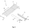
- figure 5 shows a perspective view of the individual elements of an insert according to one embodiment.
- the conductor structure 4 is shown separately from the jacket 13 here.
- the conductor structure 4 has a first cross-connection 8 provided for arrangement outside or at the edge of the joining zone 6 at a first longitudinal end and a second cross-connection 9 at a second longitudinal end of the conductor elements 5 .
- the conductor elements 5 end at the cross-connections 8, 9, so that the electrical conductor structure 4 is designed in the form of a ladder or in the form of a ladder with the cross-connections 8, 9 as bars and the conductor elements 5 as rungs.
- a coupling between the conductor elements 5 and the cross-connections 8, 9 can be designed to be fixed, in particular materially bonded, or reversibly detachable, for example with a non-positive fit. In this way, on the one hand, a common current can be applied to the conductor elements 5 and, on the other hand, a common tensile force can be applied to the conductor elements 5 .
- the cross-connections 8, 9 are also designed as conductors here. In order to avoid heating in the area of the cross-connections 8, 9 as far as possible is here a significantly larger cross section is selected than in the area of the conductor elements 5.
- the jackets 13 also provide a conductor cross section that can be directly coupled therewith.
- the jackets 13 each have a connecting conductor 14 in addition to an outer insulating layer 15 .
- This extends over the entire length of the respective casing 13, i.e. parallel to the cross-connections 8, 9 in the assembled state.
- the connecting conductors 14 are provided here with a groove 18 corresponding to the negative form of the cross-connection 8, 9, in which the cross-connections 8, 9 can be taken in a form-fitting manner.
- the coats 13 can thus be pushed laterally onto the cross-connections 8, 9.
- the insulating layer 15 also serves to provide a contact surface suitable for applying the tensile force 7 for either manual or mechanical pulling.
- the tensile force 7 is transmitted directly to the cross-connection 8 , 9 and thus to the conductor elements 5 as a result of the positive connection with the connecting conductor 14 .
- the conductor elements 5 are each elongate and straight along a common longitudinal direction 20 . In the illustrated embodiment, they run perpendicular to the cross-connections 8, 9. The form-fitting accommodation of the cross-connections 8, 9 in the groove 18 transmits forces normal to the transverse direction 19. The application of the tensile force 7 and the pulling out of the conductor elements 5 is thus automatically in the Longitudinally 20 made.
- the conductor elements 5 also each have a predetermined separation point 11, which is designed to separate the conductor element 5 by a tensile force 7 applied to at least one of the cross-connections 8, 9.
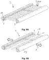
- Figure 6A shows a perspective view of an insert 3 with a separation point 11 in the central area 10 of the conductor elements 5.
- the illustration shows an assembled depositor 3, which in relation to figure 5 explained manner is constructed.
- the separating point 11 arranged in the central region 10 can be designed as a predetermined breaking point, for example.
- Figure 6B shows the insert 3 according to Figure 6A with separate conductor elements 5.
- the conductor elements 5 were all separated in the same way by a tensile force 7 applied to the jacket 13 at the separation point 11 arranged in the central area 10 .
- This can in particular be an irreversible separation, for example a break in the conductor element 5 at a predetermined breaking point as the separation point 11 .
- a reversible separation would also be conceivable, for example with a plug connection as the separation point 11.
- FIG. 7 shows a schematic sectional view of a central area 10 of a conductor element 5 according to an embodiment.
- the separation point 11 has a peripheral notch 21 in the central area 10 .
- a notch 21 acts as a crack nucleus, so that when a tensile force is applied, a crack that ultimately leads to fracture propagates from the notch 21 .
- a predetermined breaking point is provided in this way.
- FIG. 8 shows a schematic representation of a central area 10 of a conductor element 5 according to a further embodiment.
- the conductor element 5 in the central region 10 tapers continuously from both sides towards the center.
- a separation point 11 is thus provided in the area of the smallest cross section.
- such a conductor element 5 also has a temperature profile that increases towards the center when energized because of the decreasing cross section and thus increasing ohmic resistance, which is particularly advantageous for uniform heating of a joining zone 6 .
- Figure 9A shows a perspective view of an insert 3 with a separation point 11 in a joint area 12 of the conductor elements 5 with a cross connection 8.
- Such an arrangement is particularly advantageous when the conductor elements 5 are coupled in a non-positive manner to one of the cross-connections 8, 9 and the non-positive connection is overcome when they are separated.
- the separation point 11 can have a latching connection of the conductor elements 5 with the cross connection 8 . In this way, the conductor elements 5 are separated from the cross-connections 8 in the joint area 12 when the tensile force is applied.
- Figure 9B shows the insert according to Figure 9A with separate conductor elements 5.
- the frictional connection was released here by the tensile force 7 , so that the conductor elements 5 are released from the cross-connection 8 in the joint area 12 .
- An insulating coating of the conductor elements 5 is designed here to support the mechanical locking or frictional pressure. In conjunction with an anti-adhesion property of the coating, cleaning for reuse of the conductor structure 4 connected in a non-positive manner is thus made possible.
- FIG. 10 shows a schematic representation of a coupling of a conductor element 5 with a cross-connection 8 according to an embodiment.
- the cross connection 8 is formed by the jacket 13.
- the conductor element 5 here has a cylinder or ball head 22 which is received in the groove 18 of the connecting conductor 14 in a form-fitting manner. In this way, all of the conductor elements 5 can be threaded into the jacket 13 . A uniform spacing for producing a parallel arrangement of the conductor elements 5 can be ensured, for example, by spacer elements introduced into the groove 18 .
- differently shaped individual receptacles for each conductor element 5 in the jacket 13 acting as a cross connection 8 can also be provided in further embodiments.
- FIG. 11 shows a schematic representation of separable segments 8a, 8b, 8c of a cross connection 8.
- the cross connection 8 is divided here into three segments 8a, 8b, 8c of equal size, which is made possible by simply cutting to size. Of course, any other divisions or cuts are possible.
- the segments 8a, 8b, 8c can be energized individually or independently and in particular isolated from one another. Thus, if required, very individual heating of different sections of a joining zone 6 is made possible.
- the length of a joining zone 6 thus advantageously does not represent a restriction in the construction and design, which is particularly advantageous in particular in the case of large-area components, such as structural components of an aircraft or spacecraft.
Landscapes
- Engineering & Computer Science (AREA)
- Mechanical Engineering (AREA)
- Physics & Mathematics (AREA)
- Thermal Sciences (AREA)
- Lining Or Joining Of Plastics Or The Like (AREA)
- Connections Effected By Soldering, Adhesion, Or Permanent Deformation (AREA)
- Manufacturing Of Electrical Connectors (AREA)
Description
- Die vorliegende Erfindung betrifft ein Verfahren zum Verschweißen thermoplastischer Bauteile, insbesondere thermoplastischer Faserverbundstrukturbauteile für ein Luft- oder Raumfahrzeug, sowie einen Einleger zum Widerstandsschweißen thermoplastischer Bauteile, insbesondere mit einem derartigen Verfahren.
- Obwohl die vorliegende Erfindung sowie die ihr zugrunde liegende Problematik nachfolgend in Bezug auf das flächige Verschweißen thermoplastischer Faserverbundstrukturbauteile für Luft- oder Raumfahrzeuge näher beschrieben wird, ist sie darauf nicht beschränkt sondern auf vielfältige thermoplastische Bauteile anwendbar.
- Bisweilen werden flächig zu verschweißende thermoplastische Bauteile oftmals in einem statischen Prozess mit einem Heizelement verschweißt. Hierbei handelt es sich in der Regel um ein zwischen die Bauteile eingelegtes leitfähiges Gitter oder Gewebe, welche nach dem Schweißvorgang in der Fügezone verbleiben. Beispielsweise beschreibt die
DE 10 2009 047 671 A1 eine zwischen ein thermoplastisches Strukturbauteil und ein thermoplastisches Faserverbundbauteil einzubringende mit Verankerungsabschnitten versehene Metallfolie und ein Verschweißen des Faserverbundbauteils mit dem Strukturbauteil nach dem Einfügen der Metallfolie, wobei sich die Verankerungsabschnitte in das jeweils zugehörige Bauteil erstrecken. - Die Schrift
WO 2007/016152 A2 offenbart ein Verfahren zum Verbinden eines ersten Teils und eines zweiten Teils, wobei die Teile ein Polymermaterial umfassen, wobei das Verfahren umfasst: Bereitstellen eines ersten Teils mit einer Oberfläche, die eine Nut enthält; Ausrichten der Oberfläche des ersten Teils und einer Oberfläche des zweiten Teils; Anordnen eines leitenden Elements in der Nut; und Verbinden des ersten Teils und des zweiten Teils entlang der ausgerichteten Oberflächen. Die SchriftEP 1099533 A1 offenbart eine Vorrichtung zum Verbinden eines Befestigungsklammersitzes mit einer Schutzleiste, wobei die Klammer einstückig mit einer Kante der Leiste über ein Scharnier verbunden ist, wobei die Klammer Vorsprünge aufweist, die durch Biegen um das Scharnier in Kontakt mit einer Oberfläche der Leiste gebracht werden können, wobei elektrisch beheizte Elemente zwischen den Vorsprüngen und der Leiste angeordnet sind, wodurch solche Teile des Clips geschmolzen und mit der Leiste verbunden werden können; dadurch gekennzeichnet, dass ein elektrisches Drahtheizelement ein erstes elektrisches Verbindungselement aufweist, das mit einem Ende des Heizelements verbunden ist, mit einem Mittel zum Bewegen des ersten Verbindungselements und des Heizelements in Kontakt mit einer Oberfläche der Leiste, wobei ein zweites elektrisches Verbindungselement so angepasst ist, dass es das andere Ende des Heizelements berührt und mit diesem verbunden ist, eine Biegevorrichtung zum Drehen der Klammer um das Scharnier und zum Überlappen der Klammer mit der Rückseite der Leiste und zum Überlagern des Heizelements, ein Druckelement zum Halten des überlappten Klammersitzes in Position, eine Stromquelle zum Anlegen von elektrischem Strom zwischen dem ersten Verbindungselement und dem zweiten Verbindungselement, um Teile der Klammer mit der Oberfläche der Leiste zu verschmelzen, mit Mitteln, die zum anschließenden Herausziehen der Heizelemente dienen. - Vor diesem Hintergrund liegt der vorliegenden Erfindung die Aufgabe zugrunde, ein verbessertes Verfahren zum Verschweißen thermoplastischer Bauteile anzugeben.
- Erfindungsgemäß wird diese Aufgabe gelöst durch ein Verfahren zum Verschweißen thermoplastischer Bauteile mit den Merkmalen des Patentanspruchs 1 sowie durch einen Einleger zum Verschweißen thermoplastischer Bauteile mit den Merkmalen des Patentanspruchs 14.
- Demgemäß ist ein Verfahren zum Verschweißen thermoplastischer Bauteile, insbesondere thermoplastischer Faserverbundstrukturbauteile für ein Luft- oder Raumfahrzeug, vorgesehen. Das Verfahren umfasst die folgenden Schritte: Anordnen eines Einlegers, der eine Leiterstruktur mit einer Vielzahl paralleler elektrischer Leiterelemente aufweist, in einer Fügezone zwischen einem ersten thermoplastischen Bauteil und einem zweiten thermoplastischen Bauteil, so dass sich die parallelen elektrischen Leiterelemente zumindest abschnittsweise in der Fügezone befinden; Lokales Aufschmelzen der Bauteile im Bereich der Fügezone durch Bestromen der Leiterstruktur; Trennen der Leiterelemente; und Entfernen des Einlegers aus der Fügezone durch Herausziehen der getrennten Leiterelemente.
- Darüber hinaus ist ein Einleger zum Widerstandsschweißen thermoplastischer Bauteile, insbesondere mit einem erfindungsgemäßen Verfahren, vorgesehen. Der Einleger umfasst: Eine Vielzahl paralleler elektrischer Leiterelemente mit einer gemeinsamen Längsrichtung; eine erste Querverbindung an einem ersten längsseitigen Ende und eine zweite Querverbindung an einem zweiten längsseitigen Ende der Leiterelemente; und eine vorbestimmte Trennstelle an jedem Leiterelement, welche zum Trennen des Leiterelements durch eine an zumindest einer der Querverbindungen aufgebrachte Zugkraft ausgebildet ist.
- Die der vorliegenden Erfindung zugrunde liegende Idee besteht darin, einen zum Einbringen der zum Schweißen benötigten Wärme in die Fügezone vorgesehenen Einleger, auch als Inlay bezeichnet, nach dem Schmelzen des Materials in der Fügezone, insbesondere noch in einem schmelzflüssigen Zustand des Materials, aus der Fügezone zu entfernen. Erfindungsgemäß werden dazu eine Vielzahl parallel zueinander verlaufender Leiterelemente vorgesehen, welche nach dem Schmelzen in einer vorbestimmten Weise getrennt werden. Die getrennten Leiterelemente können sodann, insbesondere seitlich, aus der Fügezone herausgezogen werden.
- Vorteilhaft verbleibt somit keinerlei nach dem Schweißen nicht mehr benötigtes Einlegermaterial in der Fügezone. Auf diese Weise werden die mechanischen Eigenschaften der Fügezone verbessert. Ferner werden dabei Korrosionsaspekte eliminiert sowie innere Spannungen durch thermische Dehnung und auch Einflüsse auf Blitzableitungseigenschaften vermieden.
- Die Längen und Querschnitte der Leiterelemente sind variabel anpassbar, insbesondere hinsichtlich der Geometrie der zu fügenden Bauteile. Beispielsweise kann durch eine entsprechende Auslegung der Leiterelemente die eingebrachte Schweißenergie gesteuert werden.
- Vorzugsweise weisen die Leiterelemente eine isolierende Beschichtung auf, sodass ein Kurzschluss mit etwaigen in das thermoplastische Material eingebetteten Fasern vermieden und somit ein problemloser Einsatz bei faserverstärkten thermoplastischen Bauteilen, insbesondere auch im Falle leitfähiger Fasern, ermöglicht ist. Darüber hinaus besteht bei einer Weiterbildung die Möglichkeit, die isolierende Beschichtung in einem Randbereich der Fügezone und/oder in einem etwaigen über die Fügezone hinausgehenden Bereich der Leiterelemente lokal dicker als in einem Zentrum der Fügezone vorzusehen. Auf diese Weise wird der sogenannte "Edge Effect", unter welchem eine lokale Überhitzung am Rand einer Fügezone verstanden wird, vermieden oder minimiert.
- Erfindungsgemäß werden dabei die typischen Vorteile des Widerstandsschweißprozesses für thermoplastische Bauteile, beispielsweise der effiziente und schnelle Wärmeeintrag direkt in die Fügezone, was in geringeren thermischen Belastungen und Deformationen der zu fügenden Bauteile resultiert, beibehalten.
- Die thermoplastischen Bauteile können beispielsweise thermoplastische Faserverbundwerkstoffe mit einem thermoplastischen Matrixsystem enthalten. Beispielsweise kommen für die Anwendung bei Strukturbauteilen für Luft-oder Raumfahrzeuge hochtemperaturfeste Kunststoffe wie Polyetherketone (PEK), beispielsweise Polyetheretherketon (PEEK), Polyetherketonketon (PEKK), Polyaryletherketon (PAEK), oder auch Polyphenylensulfid (PPS) in Frage.
- Erfindungsgemäß kann insbesondere eine automatische Prozesssteuerung des Schweißprozesses realisiert werden, denn zu dem Zeitpunkt in dem das Leiterelement getrennt wird ist automatisch auch der Stromfluss unterbrochen und die Fügezone beginnt sich abzukühlen. Vorzugsweise während das thermoplastische Material noch geschmolzen ist, d.h. bevor die Temperatur unterhalb des Schmelzpunktes sinkt, werden die getrennten Leiterelemente aus der Fügezone herausgezogen und so der Einleger entfernt.
- Nach dem Entfernen des Einlegers aus der Fügezone kann eine abschließende Konsolidierung der Fügezone vorgenommen werden, insbesondere mittels eines die Bauteile miteinander verpressenden Drucks.
- Vorteilhafte Ausgestaltungen und Weiterbildungen ergeben sich aus den weiteren Unteransprüchen sowie aus der Beschreibung unter Bezugnahme auf die Figuren. Gemäß einer vorteilhaften Weiterbildung wird das Trennen der Leiterelemente durch Aufbringen einer Zugkraft auf die Leiterelemente vorgenommen. Somit können das Trennen und das Herausziehen der Leiterelemente in einen gemeinsamen Schritt erfolgen. Alternativ oder zusätzlich zu der Zugkraft kann das Trennen auch elektrisch vorgenommen oder unterstützt werden, beispielsweise durch einen zu einer Trennung des Leiterelements führenden Stromstoß.
- Gemäß einer vorteilhaften Ausführungsform sind die Leiterelemente jeweils länglich und entlang einer gemeinsamen Längsrichtung gerade ausgebildet. Das Aufbringen der Zugkraft und das Herausziehen wird entsprechend in der Längsrichtung vorgenommen. Auf diese Weise ist das Herausziehen vereinfacht und eine Beeinflussung der Fügezone wird dadurch minimiert.
- Gemäß einer Ausführungsform weist die Leiterstruktur an beiden längsseitigen Enden der Leiterelemente jeweils eine außerhalb oder am Rand der Fügezone angeordnete Querverbindung auf. Das Trennen umfasst dabei ein Abtrennen zumindest eines Abschnitts eines jeden der Leiterelemente von einer der Querverbindungen. Unter einer Leiterstruktur ist somit eine Anordnung von in Längsrichtung parallel verlaufenden elektrischen Leiterelementen und quer dazu verlaufenden elektrisch leitfähigem Querverbindungen zu verstehen. Auf diese Weise lässt sich einerseits eine gemeinsame Bestromung der Leiterelemente in einfacher Weise realisieren und zudem eine Zugkraft gemeinsam auf die Leiterelemente zum Trennen und Herausziehen derselben aufbringen. Sofern die Leiterelemente an den Querverbindungen enden kann die Leiterstruktur vor dem Trennen in der Form einer Leiter bzw. leiterförmig mit den Querverbindungen als Holme und den Leiterelementen als Sprossen gebildet sein. Eine Verbindung zwischen den Leiterelementen an den Querverbindungen kann fest, insbesondere stoffschlüssig, oder reversibel lösbar, beispielsweise kraftschlüssig, ausgebildet sein.
- Gemäß einer Ausführungsform werden die Leiterelemente in einem mittigen Bereich der Leiterelemente getrennt. Insbesondere kann dazu eine mittige Verjüngung der Leiterelemente vorgesehen sein. Die mittige Verjüngung dient als Sollbruchstelle, sodass die Leiterelemente im Bereich der Verjüngung getrennt werden. Bei der Verjüngung kann es sich beispielsweise um eine Kerbe handeln. Eine derartige Kerbe kann umlaufend oder lediglich an einer Seite des Leiterelements vorgesehen sein. Alternativ oder zusätzlich kann es sich um eine kontinuierliche Verjüngung handeln, beispielsweise eine eindimensionale Verjüngung, wie eine Abflachung, eine zweidimensionale Verjüngung, wie eine Abflachung und Schmälerung oder eine umlaufende Verjüngung, beispielsweise eine konisch zulaufende Verjüngung. Neben der Funktion als Sollbruchstelle kann über die Verjüngung auch die Wärmeverteilung entlang der Leiterelemente gesteuert werden. Insbesondere ist es durch eine mittige Verjüngung ermöglicht, ein Profil der eingebrachten ohmschen Wärme möglichst gleichmäßig zu gestalten, da mit der Variation des Querschnitts auch der ohmsche Widerstand variiert wird. Dabei sorgt die mittige Verjüngung aufgrund des lokal verringerten Querschnitts für eine höhere Wärmeabgabe in einem mittigen Bereich der Fügezone, welcher ansonsten aufgrund der Wärmeleitung in den Bauteilen kühler als ein Randbereich der Fügezone wäre bzw. länger zum Aufheizen auf eine zum Schweißen geeignete Temperatur bräuchte. Ferner kann die Verjüngung, insbesondere im Fall einer Kerbe, auch eingesetzt werden um mit einem Stromstoß am Ende des Schweißvorgangs eine lokale starke Erhitzung herbeizuführen, um so das Abtrennen zu unterstützen.
- Gemäß einer weiteren Ausführungsform werden die Leiterelemente jeweils in einem Stoßbereich mit einer der Querverbindungen getrennt. Vorteilhaft erlaubt dies eine Trennung ohne Bruch, beispielsweise mittels einer auf einem Kraft- und/oder Formschluss basierenden Kopplung und Trennung, welche reversibel ist. Als weiteren Vorteil kann das Herausziehen der gesamten Leiterelemente somit durch Aufbringen einer Zugkraft lediglich an der gegenüberliegenden Querverbindung in einer gemeinsamen Richtung vorgenommen werden.
- Gemäß einer Ausführungsform sind die Leiterelemente mit einer der Querverbindungen kraftschlüssig gekoppelt. Der Kraftschluss wird bei dem Trennen überwunden. Insbesondere wird der Kraftschluss durch die Zugkraft überwunden. Vorzugsweise ist der Kraftschluss reversibel wiederherstellbar. Auf diese Weise ist der Einleger vorteilhaft wiederverwendbar.
- Gemäß einer Ausführungsform weisen die Querverbindungen einen Mantel auf, der einen Anschlussleiter und eine Isolierschicht enthält, wobei die Zugkraft über den Mantel aufgebracht wird. Bei dem Mantel handelt es sich somit um ein funktionsintegriertes Teil, welches zur Stromversorgung, zur Isolation und zum Entfernen des Einlegers dient. Die Isolierschicht ist insbesondere gleichzeitig zur Kraftübertragung der Zugkraft ausgelegt, beispielsweise im Falle einer händischen Aufbringung der Zugkraft mit einer gut greifbaren Oberfläche oder im Falle einer maschinellen Aufbringung der Zugkraft mit einer geeigneten Koppelstelle zu einem Zugaktuator. Die Querverbindungen können, insbesondere formschlüssig, mit dem Mantel gekoppelt sein. Alternativ kann der Mantel auch die Querverbindung bilden bzw. darstellen. Ferner kann der Mantel bei einer Ausführungsform zusätzlich derart ausgebildet sein, dass er bei dem Schweißen gleichzeitig auch als seitliche Schmelzbadstütze am Rand der Fügezone dient.
- Gemäß einer Ausführungsform befindet sich ein Material der thermoplastischen Bauteile während des Entfernens im Bereich der Fügezone oberhalb seiner Schmelztemperatur. Insbesondere handelt es sich um das thermoplastische Material oder ein thermoplastisches Matrixmaterial der Bauteile. Auf diese Weise ist eine Konsolidierung nach dem Herausziehen ermöglicht.
- Gemäß einer Ausführungsform werden die Bauteile nach dem Herausziehen zumindest in dem Bereich der Fügezone zusammengepresst. Alternativ oder zusätzlich werden die Bauteile während des Aufschmelzens zusammengepresst. Während des Aufschmelzens dient dies der besseren Wärmeübertragung in das Material. Nach dem Herausziehen kann durch den äußeren Druck ein schneller Volumenausgleich und eine Konsolidierung der Fügezone vorgenommen werden.
- Gemäß einer Weiterbildung wird ein die Bauteile zusammenpressender Druck während des Trennens und/oder Herausziehens gelöst oder verringert. Auf diese Weise wird Reibung reduziert und eine Relativbewegung der Leiterelemente zu dem geschmolzenen Material erleichtert.
- Gemäß einer Ausführungsform werden die Leiterelemente bei dem Herausziehen vollständig aus der Fügezone entfernt. Auf diese Weise wird die Festigkeit der Fügezone dauerhaft gewährleistet.
- Gemäß einer Ausführungsform wird zusätzlich zu dem Einleger ein Schweißzusatzwerkstoff, insbesondere eine thermoplastische Folie, in der Fügezone angeordnet, welcher mit aufgeschmolzen wird und/oder mittels welchem bei oder nach dem Herausziehen der Leiterelemente ein Volumenausgleich vorgenommen wird. Auf diese Weise können die Leiterelemente nach dem Aufschmelzen leicht herausgezogen werden. Ferner kann anschließend eine stoffschlüssigen Verbindung der Fügezone mit hoher Festigkeit erreicht werden.
- Gemäß einer Ausführungsform ist zur Aufteilung der Fügezone in mehrere Fügeabschnitte eine Mehrzahl in Querrichtung nebeneinander angeordneter Einleger vorgesehen. Alternativ oder zusätzlich kann der Einleger in Querrichtung in eine Mehrzahl von Abschnitten, insbesondere isolierten Abschnitten, getrennt werden. Insbesondere kann dies durch Trennen der Querverbindungen vorgenommen werden. Auf diese Weise ist ein sequenzielles Fügen der Fügeabschnitte oder - sofern genügend Energiequellen zur Verfügung stehen - auch ein gemeinsames Fügen sämtlicher Fügeabschnitte ermöglicht. Es kann somit eine beliebige Länge der Fügezone realisiert werden.
- Bei einer Ausführungsform eines erfindungsgemäßen Einlegers sind die parallelen elektrischen Leiterelemente jeweils länglich und entlang einer Längsrichtung gerade ausgebildet. Auf diese Weise ist das gemeinsame Aufbringen der Zugkraft über die Querverbindung ermöglicht. Ferner können die Leiterelemente so gemeinsam in der Längsrichtung aus der Fügezone herausgezogen werden.
- Gemäß einer weiteren Ausführungsform umfasst die Trennstelle eine mittige Verjüngung der Leiterelemente. Insbesondere kann es sich um eine Kerbe oder um eine kontinuierliche Verjüngung handeln.
- Gemäß einer Ausführungsform sind die Leiterelemente mit einer der Querverbindungen kraftschlüssig gekoppelt, wobei der Kraftschluss durch die Zugkraft überwindbar ausgebildet ist. Somit kann der Einleger in einfacher vorbestimmter Weise getrennt werden. Ferner ist so eine reversibel lösbare und verbindbare Kopplung geschaffen, die eine Wiederverwendung des Einlegers erlaubt.
- Gemäß einer weiteren Ausführungsform weisen die Querverbindungen einen Mantel mit einem Querleiter und einer Isolierschicht auf, wobei die Zugkraft zum Trennen und/oder Herausziehen der Leiterelemente über den Mantel aufbringbar ist. Der Mantel kann mit einer Querverbindung gekoppelt, beispielsweise formschlüssig gekoppelt sein, oder selbst als Querverbindung vorgesehen sein.
- Gemäß einer Ausführungsform sind die Querverbindungen in Querrichtung trennbar bzw. aufteilbar ausgebildet, sodass der Einleger in eine Mehrzahl von isolierten Abschnitten aufteilbar ist. Somit ist eine Länge des Einlegers frei anpassbar.
- Gemäß einer bevorzugten Ausführungsform weisen die Leiterelemente eine elektrisch isolierende Beschichtung auf. Insbesondere ist die Beschichtung zur ausreichenden und gleichmäßigen Wärmeübertragung in die Fügezone ausgebildet.
- Gemäß einer Ausführungsform weist die elektrisch isolierende Beschichtung eine Adhäsion mit den Leiterelementen auf, welche höher als eine Adhäsion mit dem thermoplastischen Material der Bauteile vorgesehen ist. Somit wird eine Abschälung der Beschichtung bei dem Herausziehen vermieden.
- Gemäß einer Ausführungsform enthält die Beschichtung eine Antihaftbeschichtung, sodass bei dem Herausziehen kein thermoplastisches Material aus der Fügezone herausgezogen wird. Beispielsweise kann dazu eine Antihaftbeschichtung an der äußeren Oberfläche einer Isolation vorgesehen sein. Die Antihaftbeschichtung kann ferner dienlich sein um im Falle einer reversiblen Trennung eine Reinigung zur Wiederverwendung der Leiterstruktur zu erleichtern.
- Gemäß einer Ausführungsform ist die Beschichtung im Falle eine kraftschlüssigen Verbindung zwischen Leiterelement und Querverbindung zur Abstützung der mechanischen Verschluss- bzw. Kraftschlusspressung ausgelegt. Somit bleibt eine Wiederverwendbarkeit gewährleistet.
- Die obigen Ausgestaltungen und Weiterbildungen lassen sich, sofern sinnvoll, beliebig miteinander kombinieren. Weitere mögliche Ausgestaltungen, Weiterbildungen und Implementierungen der Erfindung umfassen auch nicht explizit genannte Kombinationen von zuvor oder im Folgenden bezüglich der Ausführungsbeispiele beschriebenen Merkmale der Erfindung. Insbesondere wird dabei der Fachmann auch Einzelaspekte als Verbesserungen oder Ergänzungen zu der jeweiligen Grundform der vorliegenden Erfindung hinzufügen.
- Die vorliegende Erfindung wird nachfolgend anhand der in den schematischen Figuren angegebenen Ausführungsbeispiele näher erläutert. Es zeigen dabei:
- Fig. 1
- eine schematische perspektivische Darstellung eines zwischen zwei thermoplastischen Bauteilen angeordneten Einlegers;
- Fig. 2
- den Einleger gemäß
Fig. 1 mit einer Stromversorgung zum Verschweißen der Bauteile; - Fig. 3
- den Einleger gemäß
Fig. 1 und 2 mit getrennten Leiterelementen; - Fig. 4
- eine schematische Schnittansicht einer konsolidierten Fügezone nach dem Herausziehen der Leiterelemente;
- Fig. 5
- eine perspektivische Darstellung der einzelnen Elemente eines Einlegers gemäß einer Ausführungsform;
- Fig. 6A
- eine perspektivische Darstellung eines Einlegers mit einer Trennstelle im mittigen Bereich der Leiterelemente;
- Fig. 6B
- der Einleger gemäß
Fig. 6A mit getrennten Leiterelementen; - Fig. 7
- eine schematische Schnittdarstellung eines mittigen Bereichs eines Leiterelements gemäß einer Ausführungsform;
- Fig. 8
- eine schematische Darstellung eines mittigen Bereich eines Leiterelements gemäß einer weiteren Ausführungsform;
- Fig. 9A
- eine perspektivische Darstellung eines Einlegers mit einer Trennstelle in einem Stoßbereich der Leiterelemente mit einer Querverbindung;
- Fig. 9B
- der Einleger gemäß
Fig. 9A mit getrennten Leiterelementen; - Fig. 10
- eine schematische Darstellung einer Kopplung eines Leiterelements mit einer Querverbindung gemäß einer Ausführungsform;
- Fig. 11
- eine schematische Darstellung trennbarer Bereiche einer Querverbindung; und
- Fig. 12
- eine schematische Darstellung einer Aneinanderreihung von Einlegern in einer gemeinsamen Fügezone.
- Die beiliegenden Figuren sollen ein weiteres Verständnis der Ausführungsformen der Erfindung vermitteln. Sie veranschaulichen Ausführungsformen und dienen im Zusammenhang mit der Beschreibung der Erklärung von Prinzipien und Konzepten der Erfindung. Andere Ausführungsformen und viele der genannten Vorteile ergeben sich im Hinblick auf die Zeichnungen. Die Elemente der Zeichnungen sind nicht notwendigerweise maßstabsgetreu zueinander gezeigt.
- In den Figuren der Zeichnung sind gleiche, funktionsgleiche und gleich wirkende Elemente, Merkmale und Komponenten - sofern nichts anderes ausgeführt ist - jeweils mit denselben Bezugszeichen versehen.
-
Fig. 1 zeigt eine schematische perspektivische Darstellung eines zwischen zwei Bauteilen 1, 2 angeordneten Einlegers 3. - Rein schematisch sind die Bauteile 1, 2 hier zur Illustration quaderförmig dargestellt. Selbstverständlich kann es sich bei weiteren Ausführungsformen auch um unterschiedlichste andersartige Bauteilgeometrien, beispielsweise gewölbte Bauteile oder dergleichen, handeln. Denkbar wäre beispielsweise Strukturteile eines Luft oder Raumfahrzeugs, wie Teile eines Flugzeugrumpfes oder dergleichen, zum Fügen derselben auf diese Weise anzuordnen.
- Der Einleger 3 weist eine Leiterstruktur 4 mit einer Vielzahl paralleler elektrisch leitender Leiterelemente 5 auf. Die Leiterelemente 5 sind in einer Fügezone 6 zwischen dem ersten thermoplastischen Bauteil 1 und dem zweiten thermoplastischen Bauteil 2 angeordnet und befinden sich somit zumindest abschnittsweise in der Fügezone 6.
- Neben den Leiterelementen 5 weist die Leiterstruktur 4 an beiden längsseitigen Enden der Leiterelemente 5 jeweils eine außerhalb oder am Rand der Fügezone 6 angeordnete Querverbindung 8, 9 auf, welche mit einem isolierenden Mantel 13 versehen sind. Bei der dargestellten Ausführungsform sind die Querverbindungen 8, 9 rein schematisch mit rundem Querschnitt dargestellt. Die jeweiligen Mäntel 13 sind rein beispielhaft mit einem halbovalen Querschnitt dargestellt. Selbstverständlich sind unterschiedlichste Querschnittsformen möglich und an die Bauteil- und Stoßsituation anpassbar.
- Darüber hinaus ist hier zusätzlich zu dem Einleger 3 ein Schweißzusatzwerkstoff 16 in der Fügezone 6 angeordnet. Beispielsweise kann es sich dabei um eine thermoplastische Folie handeln. Ein derartiger Schweißzusatzwerkstoff ist lediglich optional und kann je nach Art der zu fügenden Werkstoffe und Geometrie des Einlegers vorgesehen oder weggelassen bzw. in unterschiedlicher Weise und unterschiedlicher Menge vorgesehen werden. Beispielsweise wäre es denkbar, zwischen den Leiterelementen vorgesehene Zwischenräume mit dem Schweißzusatzwerkstoff auszufüllen. Der Schweißzusatzwerkstoff 16 kann in unterschiedlichster Form, neben Folien beispielsweise auch in Block-, Draht-, Pulver- oder Granulatform, vorgesehen sein.
-
Fig. 2 zeigt den zwischen die Bauteile 1, 2 eingelegten Einleger 3 gemäßFig. 1 mit einer Stromversorgung zum Verschweißen der Bauteile 1,2. - Die Stromversorgung kann insbesondere mit einem in dem Mantel 13 integrierten Anschlussleiter gekoppelt sein. Es handelt sich bei der Stromversorgung beispielsweise um eine Gleichstrom- und/oder Wechselstromquelle. Mit der Stromversorgung lässt sich der Einleger somit als Wärmeleitungselement zum Widerstandsschweißen der Bauteile 1 und 2 als Fügepartner einsetzen. Durch lokales Schmelzen der Bauteile 1, 2 und ihrer jeweiligen Oberflächen im Bereich der Fügezone 6 mittels des Einlegers 3 wird eine chemische beziehungsweise stoffschlüssige Verbindung zwischen den Bauteilen 1, 2 hergestellt. Die dazu benötigte Wärme wird mittels elektrischer Energie, welche durch den elektrischen Widerstand der Leiterelemente in thermische Energie umgewandelt wird, direkt in der Fügezone 6 abgegeben. Der elektrische Energieeintrag kann dabei über den Prozess variabel vorgesehen sein. Auf diese Weise werden die Bauteile 1, 2 lokal im Bereich der Fügezone durch Bestromen des Einlegers 3 aufgeschmolzen, wie hier mit dem um die Leiterelemente 5 herum dargestellten gepunkteten Bereich illustriert. Darüber hinaus wird auch der Schweißzusatzwerkstoff 16 aufgeschmolzen.
- Die Leiterelemente 5 weisen eine elektrisch isolierende Beschichtung auf, welche etwaige Kurzschlüsse mit etwaigen in den Bauteilen 1, 2 enthaltenen Verstärkungsfasern verhindert. Die Beschichtung ist gleichzeitig dünn genug ausgebildet, um eine ausreichende und gleichmäßige Wärmeübertragung von dem Leiterelement 5 in die Fügezone 6 zu erlauben.
-
Fig. 3 zeigt den Einleger 3 gemäßFig. 1 und 2 mit getrennten Leiterelementen 5. - Das Trennen der Leiterelemente 5 wird durch Aufbringen einer hier lediglich schematisch mit Pfeilen dargestellten Zugkraft 7 auf die Leiterelemente 5 vorgenommen. Die Zugkraft 7 wird beispielsweise über den Mantel 13 der Querverbindungen aufgebracht. Sie kann dazu maschinell oder manuell an dem Mantel 13 angelegt werden.
- Die Zugkraft 7 führt zu einem Abtrennen zumindest eines Abschnitts eines jeden der Leiterelemente 5 von einer der Querverbindungen 8, 9. Mit der anderen der beiden Querverbindungen 8, 9 bleibt der Abschnitt des Leiterelements 5 verbunden. Sind die Leiterelemente 5 durch die Zugkraft 7 getrennt, können Sie somit dennoch aus der Fügezone 6 seitlich herausgezogen werden. Die Leiterelemente 5 werden bei dem Herausziehen, vorzugsweise vollständig, aus der Fügezone 6 entfernt.
- Auf diese Weise wird der komplette Einleger 3 aus der Fügezone 6 durch Herausziehen der getrennten Leiterelemente 5 entfernt. Durch den Schweißzusatzwerkstoff 16 wird bei dem Herausziehen der Leiterelemente 5 ein Volumenausgleich in der Fügezone 6 vorgenommen, sodass es nicht zu Einschlüssen kommt.
- Das Material der thermoplastischen Bauteile 1, 2 bzw. im Falle faserverstärkte Bauteile deren thermoplastische Matrix befindet sich während des Entfernens des Einlegers 3 im Bereich der Fügezone 6 oberhalb seiner Schmelztemperatur, sodass eine anschließende Konsolidierung ermöglicht ist.
- Die isolierende Beschichtung der Leiterelemente 5 weist eine Adhäsion mit den Leiterelementen auf, welche höher als eine Adhäsion mit dem thermoplastischen Material der Bauteile 1, 2 vorgesehen ist. Somit wird eine Abschälung der Beschichtung bei dem Herausziehen vermieden. Ferner kann die Beschichtung eine Antihaftbeschichtung aufweisen, sodass bei dem Herausziehen kein thermoplastisches Material aus der Fügezone 6 mit herausgezogen wird.
-
Fig. 4 zeigt eine schematische Schnittansicht einer konsolidierten Fügezone 6 nach dem Herausziehen der Leiterelemente 5. - Zum Konsolidieren wird ein hier schematisch mit Pfeilen dargestellter Druck 17 auf die Fügezone 6 ausgeübt. Denkbar wäre ferner ein Nachwärmen der Fügezone 6, um etwaige innere Spannungen abzubauen.
- Ferner können auch bereits während des Aufschmelzens die Bauteile 1, 2 zumindest in dem Bereich der Fügezone 6 zusammengepresst werden. Auf diese Weise wird die Wärmeleitung in der Fügezone 6 verbessert. Der die Bauteile 1, 2 zusammenpressende Druck 17 wird jedoch während des Trennens und/oder Herausziehens gelöst oder verringert, um die Reibung zu reduzieren und ein Herausziehen der Leiterelemente zu erlauben, möglichst ohne dass schmelzflüssiges Material der Fügezone 6 mit herausgezogen wird.
-
Fig. 5 zeigt eine perspektivische Darstellung der einzelnen Elemente eines Einlegers gemäß einer Ausführungsform. - Die Leiterstruktur 4 ist hier separat von dem Mantel 13 dargestellt. Gemäß der dargestellten Ausführungsform weist die Leiterstruktur 4 jeweils eine zur Anordnung außerhalb oder am Rand der Fügezone 6 vorgesehene erste Querverbindung 8 an einem ersten längsseitigen Ende und zweite Querverbindung 9 an einem zweiten längsseitigen Ende der Leiterelemente 5 auf. Die Leiterelemente 5 enden an den Querverbindungen 8, 9, sodass die elektrische Leiterstruktur 4 in der Form einer Leiter bzw. leiterförmig mit den Querverbindungen 8, 9 als Holmen und den Leiterelementen 5 als Sprossen ausgebildet ist.
- Eine Kopplung zwischen den Leiterelementen 5 und den Querverbindungen 8, 9 kann fest, insbesondere stoffschlüssig, oder reversibel lösbar, beispielsweise kraftschlüssig, ausgebildet sein. Auf diese Weise lässt sich einerseits eine gemeinsame Bestromung der Leiterelemente 5 und zudem eine gemeinsame Zugkraft auf die Leiterelemente 5 aufbringen.
- Die Querverbindungen 8, 9 sind hier ebenfalls als Leiter ausgebildet. Um eine Erwärmung im Bereich der Querverbindungen 8, 9 möglichst zu vermeiden ist hier ein deutlich größerer Querschnitt gewählt als im Bereich der Leiterelemente 5. Zusätzlich stellen auch die Mäntel 13 einen damit direkt koppelbaren Leiterquerschnitt bereit.
- Die Mäntel 13 weisen dazu jeweils neben einer äußeren Isolierschicht 15 einen Anschlussleiter 14 auf. Dieser erstreckt sich über die gesamte Länge des jeweiligen Mantels 13, d.h. im montierten Zustand parallel zu den Querverbindungen 8, 9. Die Anschlussleiter 14 sind hier mit einer der Negativform der Querverbindung 8, 9 entsprechenden Nut 18 versehen, in welcher die Querverbindungen 8, 9 formschlüssig aufnehmbar sind. Zur Montage lassen sich die Mäntel 13 somit auf die Querverbindungen 8, 9 seitlich aufschieben.
- Die Isolierschicht 15 dient neben der Isolation auch der Bereitstellung einer zum Aufbringen der Zugkraft 7 geeigneten Angriffsfläche für entweder ein manuelles oder maschinelles Ziehen. Durch den Formschluss mit dem Anschlussleiter 14 wird die Zugkraft 7 direkt auf die Querverbindung 8, 9 und somit auf die Leiterelemente 5 übertragen.
- Die Leiterelemente 5 sind jeweils länglich und entlang einer gemeinsamen Längsrichtung 20 gerade ausgebildet. In der dargestellten Ausführungsform verlaufen sie senkrecht zu den Querverbindungen 8, 9. Die formschlüssige Aufnahme der Querverbindungen 8, 9 in der Nut 18 überträgt Kräfte normal zu der Querrichtung 19. Das Aufbringen der Zugkraft 7 und das Herausziehen der Leiterelemente 5 wird somit automatisch in der Längsrichtung 20 vorgenommen.
- Die Leiterelemente 5 weisen ferner jeweils eine vorbestimmten Trennstelle 11 auf, welche zum Trennen des Leiterelements 5 durch eine an zumindest einer der Querverbindungen 8, 9 aufgebrachte Zugkraft 7 ausgebildet ist.
-
Fig. 6A zeigt eine perspektivische Darstellung eines Einlegers 3 mit einer Trennstelle 11 im mittigen Bereich 10 der Leiterelemente 5. - Die Darstellung zeigt einen montierten Einleger 3, der in der in Bezug auf
Fig. 5 erläuterten Weise aufgebaut ist. Die in dem mittigen Bereich 10 angeordnete Trennstelle 11 kann beispielsweise als Sollbruchstelle ausgebildet sein. -
Fig. 6B zeigt der Einleger 3 gemäßFig. 6A mit getrennten Leiterelementen 5. - Die Leiterelement 5 wurden alle gleichermaßen durch eine an dem Mantel 13 aufgebrachte Zugkraft 7 an der in dem mittigen Bereich 10 angeordneten Trennstelle 11 getrennt. Hierbei kann es sich insbesondere um eine irreversible Trennung, beispielsweise einen Bruch des Leiterelements 5 an einer Sollbruchstelle als Trennstelle 11, handeln. Bei weiteren Ausführungsformen wäre auch eine reversible Trennung denkbar, beispielsweise mit einer Steckverbindung als Trennstelle 11.
-
Fig. 7 zeigt eine schematische Schnittdarstellung eines mittigen Bereichs 10 eines Leiterelements 5 gemäß einer Ausführungsform. - Bei dieser Ausführungsform weist die Trennstelle 11 in dem mittigen Bereich 10 eine umlaufende Kerbe 21 auf. Eine derartige Kerbe 21 fungiert als Risskeim, sodass sich bei Aufbringen einer Zugkraft ein letztlich zum Bruch führender Riss ausgehend von der Kerbe 21 ausbreitet. Auf diese Weise ist eine Sollbruchstelle bereitgestellt.
-
Fig. 8 zeigt eine schematische Darstellung eines mittigen Bereichs 10 eines Leiterelements 5 gemäß einer weiteren Ausführungsform. - Bei dieser Ausführungsform läuft das Leiterelement 5 in dem mittigen Bereich 10 stetig von beiden Seiten zur Mitte hin konisch zu. Eine Trennstelle 11 ist somit im Bereich eines geringsten Querschnitts vorgesehen. Bei Aufbringen einer Zugkraft schnürt sich das Leiterelement 5 im Bereich dieser Trennstelle mit zunehmender Zugkraft immer weiter ein, bis es zu einem Bruch kommt.
- Weiterhin weist ein derartiges Leiterelement 5 bei der Bestromung auch ein zur Mitte hin wegen des sinkenden Querschnitts und somit steigenden ohmschen Widerstands ansteigendes Temperaturprofil auf, was zur gleichmäßigen Erwärmung einer Fügezone 6 besonders vorteilhaft ist.
- Sowohl bei der Ausführungsform nach
Fig. 7 als auch bei der Ausführungsform nachFig. 8 werden die Leiterelemente 5 somit in dem mittigen Bereich 10 der Leiterelemente 5 getrennt. -
Fig. 9A zeigt eine perspektivische Darstellung eines Einlegers 3 mit einer Trennstelle 11 im einem Stoßbereich 12 der Leiterelemente 5 mit einer Querverbindung 8. - Eine derartige Anordnung ist insbesondere dann vorteilhaft, wenn die Leiterelemente 5 mit einer der Querverbindungen 8, 9 kraftschlüssig gekoppelt sind und der Kraftschluss bei dem Trennen überwunden wird. Beispielsweise kann dazu die Trennstelle 11 eine Rastverbindung der Leiterelemente 5 mit der Querverbindung 8 aufweisen. Die Leiterelemente 5 werden auf diese Weise bei Aufbringen der Zugkraft jeweils in dem Stoßbereich 12 von der Querverbindungen 8 getrennt.
-
Fig. 9B zeigt den Einleger gemäßFig. 9A mit getrennten Leiterelementen 5. - Durch die Zugkraft 7 wurde hier die kraftschlüssige Verbindungen gelöst, sodass die Leiterelemente 5 in dem Stoßbereich 12 von der Querverbindung 8 gelöst sind.
- Eine isolierende Beschichtung der Leiterelemente 5 ist hier zur Abstützung der mechanischen Verschluss- bzw. Kraftschlusspressung ausgelegt. In Verbindung mit einer Antihafteigenschaft der Beschichtung ist somit eine Reinigung zur Wiederverwendung der kraftschlüssig verbundenen Leiterstruktur 4 ermöglicht.
-
Fig. 10 zeigt eine schematische Darstellung einer Kopplung eines Leiterelements 5 mit einer Querverbindung 8 gemäß einer Ausführungsform. - In diesem Fall ist die Querverbindung 8 durch den Mantel 13 gebildet. Das Leiterelement 5 weist hier einen Zylinder- oder Kugelkopf 22 auf, welcher in der Nut 18 des Anschlussleiters 14 formschlüssig aufgenommen ist. Auf diese Weise können sämtliche Leiterelemente 5 in dem Mantel 13 aufgefädelt werden. Ein gleichmäßiger Abstand zur Herstellung einer parallelen Anordnung der Leiterelemente 5 kann beispielsweise durch in die Nut 18 eingebrachte Abstandselemente gewährleistet werden. Selbstverständlich können bei weiteren Ausführungsformen auch anders geformte individuelle Aufnahmen für jedes Leiterelement 5 in dem als Querverbindung 8 fungierenden Mantel 13 vorgesehen sein.
- Eine derartige Anordnung mit einer individuellen Aufnahme eines jeden Leiterelements 5 in dem Querverbindungselement 8 ermöglicht besonders vorteilhaft eine völlig freie und insbesondere auch nachträglich mögliche Trennbarkeit des Einlegers 3 in Querrichtung 19. Auf diese Weise ist der Einleger 3 beispielsweise durch Trennen der Querverbindung 8 auf eine gewünschte Länge zuschneidbar.
-
Fig. 11 zeigt eine schematische Darstellung trennbarer Segmente 8a, 8b, 8c einer Querverbindung 8. - Rein beispielhaft ist die Querverbindung 8 hier in drei gleich große Segmente 8a, 8b, 8c getrennt, was durch einfaches zuschneiden ermöglicht ist. Selbstverständlich sind beliebige andere Aufteilungen bzw. Zuschnitte möglich. Auf diese Weise können die Segmente 8a, 8b, 8c individuell bzw. unabhängig und insbesondere isoliert voneinander bestromt werden. Somit ist bei Bedarf eine sehr individuelle Erwärmung unterschiedlicher Abschnitte einer Fügezone 6 ermöglicht.
-
Fig. 12 zeigt eine schematische Darstellung einer Aneinanderreihung von Einlegern 3 in einer gemeinsamen Fügezone 6. - Dazu können mehrere der in Bezug auf die
Figuren 5 bis 9 beschriebenen Einleger in Querrichtung nebeneinander angeordnet und somit Fügeabschnitte 6a, 6b, 6c,..., 6n gebildet werden. Diese können entweder sequenziell oder mit mehreren Stromquellen gleichzeitig bestromt werden. Damit kann eine beliebige Länge einer Fügezone 6 gefügt werden. Die Länge einer Fügezone 6 stellt somit vorteilhaft keine Beschränkung bei der Konstruktion und Auslegung dar, was insbesondere bei großflächigen Bauteilen, wie Strukturbauteilen eines Luft- oder Raumfahrzeugs, besonders vorteilhaft ist. - Obwohl die vorliegende Erfindung anhand bevorzugter Ausführungsbeispiele vorstehend vollständig beschrieben wurde, ist sie darauf nicht beschränkt, sondern auf vielfältige Art und Weise modifizierbar. Insbesondere sind unterschiedlichste Querschnittsformen der Leiterelemente, beispielsweise neben runden auch flache oder eckige Querschnittsformen, möglich.
-
- 1
- Bauteil
- 2
- Bauteil
- 3
- Einleger
- 4
- Leiterstruktur
- 5
- Leiterelement
- 6
- Fügezone
- 7
- Zugkraft
- 8
- Querverbindung
- 9
- Querverbindung
- 10
- mittiger Bereich
- 11
- Trendstelle
- 12
- Stoßbereich
- 13
- Mantel
- 14
- Anschlussleiter
- 15
- Isolierschicht
- 16
- Schweißzusatzwerkstoff
- 17
- Druck
- 18
- Nut
- 19
- Querrichtung
- 20
- Längsrichtung
- 21
- Kerbe
- 22
- Zylinder-oder Kugelkopf
Claims (15)
- Verfahren zum Verschweißen thermoplastischer Bauteile (1, 2), insbesondere thermoplastischer Faserverbundstrukturbauteile für ein Luft- oder Raumfahrzeug, mit den Schritten:Anordnen eines Einlegers (3), der eine Leiterstruktur (4) mit einer Vielzahl paralleler elektrischer Leiterelemente (5) aufweist, in einer Fügezone (6) zwischen einem ersten thermoplastischen Bauteil (1) und einem zweiten thermoplastischen Bauteil (2), so dass sich die parallelen elektrischen Leiterelemente (5) zumindest abschnittsweise in der Fügezone (6) befinden;Lokales Aufschmelzen der Bauteile (1, 2) im Bereich der Fügezone (6) durch Bestromen der Leiterstruktur (4);gekennzeichnet durchTrennen der Leiterelemente (5); undEntfernen des Einlegers (3) aus der Fügezone (6) durch Herausziehen der getrennten Leiterelemente (5).
- Verfahren nach Anspruch 1, wobei das Trennen der Leiterelemente (5) durch Aufbringen einer Zugkraft (7) auf die Leiterelemente (5) vorgenommen wird.
- Verfahren nach Anspruch 1 oder 2, wobei die Leiterelemente (5) jeweils länglich und entlang einer gemeinsamen Längsrichtung (20) gerade ausgebildet sind, wobei das Aufbringen der Zugkraft (7) und das Herausziehen in der Längsrichtung (20) vorgenommen wird.
- Verfahren nach einem der vorangehenden Ansprüche, wobei die Leiterstruktur (4) an beiden längsseitigen Enden der Leiterelemente (5) jeweils eine außerhalb oder am Rand der Fügezone (6) angeordnete Querverbindung (8, 9) aufweist, wobei das Trennen ein Abtrennen zumindest eines Abschnitts eines jeden der Leiterelemente (5) von einer der Querverbindungen (8, 9) umfasst.
- Verfahren nach einem der vorangehenden Ansprüche, wobei die Leiterelemente (5) in einem mittigen Bereich (10) der Leiterelemente getrennt werden, insbesondere im Bereich einer mittigen Verjüngung (11) der Leiterelemente.
- Verfahren nach Anspruch 4 oder 5, wobei die Leiterelemente (5) jeweils in einem Stoßbereich (12) mit einer der Querverbindungen (8, 9) getrennt werden.
- Verfahren nach Anspruch 6, wobei die Leiterelemente (5) mit einer der Querverbindungen (8, 9) kraftschlüssig gekoppelt sind und der Kraftschluss bei dem Trennen überwunden wird.
- Verfahren nach einem der Ansprüche 2 bis 7, wobei die Querverbindungen einen Mantel (13) aufweisen der einen Anschlussleiter (14) und eine Isolierschicht (15) enthält, wobei die Zugkraft (7) über den Mantel (13) aufgebracht wird.
- Verfahren nach einem der vorangehenden Ansprüche, wobei sich ein Material der thermoplastischen Bauteile (1, 2) während des Entfernens im Bereich der Fügezone (6) oberhalb seiner Schmelztemperatur befindet.
- Verfahren nach einem der vorangehenden Ansprüche, wobei die Bauteile (1, 2) während des Aufschmelzens und/oder nach dem Herausziehen zumindest in dem Bereich der Fügezone (6) zusammengepresst werden.
- Verfahren nach Anspruch 10, wobei ein die Bauteile (1, 2) zusammenpressender Druck (17) während des Trennens und/oder Herausziehens gelöst oder verringert wird.
- Verfahren nach einem der vorangehenden Ansprüche, wobei zusätzlich zu dem Einleger (3) ein Schweißzusatzwerkstoff (16), insbesondere eine thermoplastische Folie, in der Fügezone (6) angeordnet wird, welcher mit aufgeschmolzen wird und/oder mittels welchem, insbesondere bei dem Herausziehen der Leiterelemente (5), ein Volumenausgleich vorgenommen wird.
- Verfahren nach einem der vorangehenden Ansprüche, wobei zur Aufteilung der Fügezone (6) in mehrere Fügeabschnitte (6a, 6b, 6c, ... 6n) eine Mehrzahl in Querrichtung nebeneinander angeordneter Einleger (3) vorgesehen ist oder der Einleger (3) in Querrichtung in eine Mehrzahl von Abschnitten getrennt wird, insbesondere durch Trennen der Querverbindungen (8, 9).
- Einleger (3) zum Widerstandsschweißen thermoplastischer Bauteile, insbesondere mit einem Verfahren gemäß einem der vorangehenden Ansprüche, mit:einer Vielzahl paralleler elektrischer Leiterelemente (5) mit einer gemeinsamen Längsrichtung (20);einer ersten Querverbindung (8) an einem ersten längsseitigen Ende und einer zweiten Querverbindung (9) an einem zweiten längsseitigen Ende der Leiterelemente (5);gekennzeichnet durcheine vorbestimmten Trennstelle (11) an jedem Leiterelement (5), welche zum Trennen des Leiterelements (5) durch eine an zumindest einer der Querverbindungen (8, 9) aufgebrachte Zugkraft (7) ausgebildet ist.
- Einleger nach Anspruch 14, wobei die Leiterelemente (5) eine elektrisch isolierende Beschichtung aufweisen, welche eine Wärmeübertragung zulässt und/oder eine Antihaftbeschichtung enthält.
Applications Claiming Priority (2)
| Application Number | Priority Date | Filing Date | Title |
|---|---|---|---|
| DE102018217586.1A DE102018217586A1 (de) | 2018-10-15 | 2018-10-15 | Verfahren und Einleger zum Verschweißen thermoplastischer Bauteile |
| PCT/EP2019/077991 WO2020079010A1 (de) | 2018-10-15 | 2019-10-15 | Verfahren und einleger zum verschweissen thermoplastischer bauteile |
Publications (2)
| Publication Number | Publication Date |
|---|---|
| EP3867044A1 EP3867044A1 (de) | 2021-08-25 |
| EP3867044B1 true EP3867044B1 (de) | 2023-01-04 |
Family
ID=68281454
Family Applications (1)
| Application Number | Title | Priority Date | Filing Date |
|---|---|---|---|
| EP19789667.3A Active EP3867044B1 (de) | 2018-10-15 | 2019-10-15 | Verfahren und einleger zum verschweissen thermoplastischer bauteile |
Country Status (5)
| Country | Link |
|---|---|
| US (1) | US11618222B2 (de) |
| EP (1) | EP3867044B1 (de) |
| CN (1) | CN112867598B (de) |
| DE (1) | DE102018217586A1 (de) |
| WO (1) | WO2020079010A1 (de) |
Families Citing this family (5)
| Publication number | Priority date | Publication date | Assignee | Title |
|---|---|---|---|---|
| CN112123793A (zh) * | 2020-08-13 | 2020-12-25 | 上海复合材料科技有限公司 | 曲面蜂窝的拼接方法 |
| FR3117400B1 (fr) | 2020-12-11 | 2024-03-01 | Stelia Aerospace | Système et procédé de solidarisation de pièces thermoplastiques hautes performances |
| EP4241967A1 (de) | 2022-03-07 | 2023-09-13 | Rohr, Inc. | Shimmen von geschweissten grenzflächen zwischen thermoplastischen komponenten |
| TR2023017517A2 (tr) | 2023-12-18 | 2025-06-23 | Tusas Tuerk Havacilik Ve Uzay Sanayii Anonim Sirketi | Bir Kaynak Tezgâhı. |
| FR3161873A1 (fr) | 2024-05-03 | 2025-11-07 | Airbus Atlantic | Dispositif et procédé de solidarisation de pièces thermoplastiques |
Citations (1)
| Publication number | Priority date | Publication date | Assignee | Title |
|---|---|---|---|---|
| EP1099533B1 (de) * | 1999-11-10 | 2004-04-21 | Munekata Co., Ltd. | Vorrichtung zum Heissverbinden von Kunststoffbändern und -clips |
Family Cites Families (13)
| Publication number | Priority date | Publication date | Assignee | Title |
|---|---|---|---|---|
| DE1136814B (de) * | 1956-10-03 | 1962-09-20 | Basf Ag | Verfahren und Vorrichtung zum Verschweissen von Kunststoffrohren |
| US3480505A (en) * | 1965-08-09 | 1969-11-25 | Union Carbide Corp | Heat sealing |
| US3769124A (en) * | 1972-03-21 | 1973-10-30 | Mobil Oil Corp | Method and apparatus for splicing foam sheet material |
| US4110506A (en) * | 1976-09-08 | 1978-08-29 | Bhn Corporation | Thermoplastic control complex |
| JPS5770612A (en) * | 1980-10-21 | 1982-05-01 | Sumitomo Bakelite Co Ltd | Bonding method of thermoplastic resin molded object |
| FR2648076B1 (fr) * | 1989-06-09 | 1991-11-15 | Boulet D Auria Terlizzi | Fil gaine profile destine notamment a former un insert d'electro-soudure |
| US7126096B1 (en) * | 1991-04-05 | 2006-10-24 | Th Boeing Company | Resistance welding of thermoplastics in aerospace structure |
| GB9226795D0 (en) * | 1992-12-23 | 1993-02-17 | Short Michael C | Jointing plastics sheets |
| JP4542926B2 (ja) * | 2005-03-15 | 2010-09-15 | 株式会社東芝 | 接合方法 |
| KR20080031466A (ko) | 2005-07-27 | 2008-04-08 | 어플라이드 머티어리얼스, 인코포레이티드 | 플라스틱의 열선 용접 방법 |
| DE102009026216A1 (de) * | 2009-07-21 | 2011-01-27 | Benecke-Kaliko Ag | Flexibles Flächengebilde |
| DE102009047671A1 (de) | 2009-12-08 | 2011-06-09 | Airbus Operations Gmbh | Verfahren zum Anbinden eines Faserverbundbauteils an ein Strukturbauteil eines Luft- und Raumfahrzeuges und eine entsprechende Anordnung |
| EP3034276B1 (de) * | 2014-12-19 | 2021-06-30 | Airbus Defence and Space GmbH | Bauteil mit stoffschlüssiger Verbindung und ein Fügeverfahren |
-
2018
- 2018-10-15 DE DE102018217586.1A patent/DE102018217586A1/de not_active Withdrawn
-
2019
- 2019-10-15 WO PCT/EP2019/077991 patent/WO2020079010A1/de not_active Ceased
- 2019-10-15 EP EP19789667.3A patent/EP3867044B1/de active Active
- 2019-10-15 US US17/285,003 patent/US11618222B2/en active Active
- 2019-10-15 CN CN201980068221.3A patent/CN112867598B/zh active Active
Patent Citations (1)
| Publication number | Priority date | Publication date | Assignee | Title |
|---|---|---|---|---|
| EP1099533B1 (de) * | 1999-11-10 | 2004-04-21 | Munekata Co., Ltd. | Vorrichtung zum Heissverbinden von Kunststoffbändern und -clips |
Also Published As
| Publication number | Publication date |
|---|---|
| DE102018217586A1 (de) | 2020-04-16 |
| CN112867598B (zh) | 2025-09-23 |
| US11618222B2 (en) | 2023-04-04 |
| CN112867598A (zh) | 2021-05-28 |
| US20210387424A1 (en) | 2021-12-16 |
| WO2020079010A1 (de) | 2020-04-23 |
| EP3867044A1 (de) | 2021-08-25 |
Similar Documents
| Publication | Publication Date | Title |
|---|---|---|
| WO2020079010A1 (de) | Verfahren und einleger zum verschweissen thermoplastischer bauteile | |
| DE69317812T2 (de) | Heizelement für eine Schlauch-Ankuppel-Anordnung | |
| DE69708405T2 (de) | Spritzgiessdüseverfahren unter Verwendung eines Elementes zum Fixieren und Abdichten eines Kontakdrahtes | |
| EP2821198A1 (de) | Faserhalbzeug-Ablegekopf | |
| EP1467599A2 (de) | Vorrichtung zur Aufnahme von Keramik-Heizelementen und Verfahren zur Herstellung einer solchen | |
| EP3339633B1 (de) | Verfahren zur herstellung einer potentialausgleichsverbindung an einem windenergieanlagenrotorblatt | |
| DE102008008200A1 (de) | Verbundstruktur sowie Verfahren zu ihrer Herstellung | |
| EP2205419A1 (de) | Angussadapter sowie angusssystem für einen angussadapter | |
| EP2695687B1 (de) | Verfahren zur herstellung eines bauteils mit einer verbundstruktur | |
| WO2023104372A1 (de) | Verfahren zur herstellung eines elektromotors | |
| DE10333451A1 (de) | Vorrichtung zur Aufnahme von Keramik-Heizelementen und Verfahren zur Herstellung einer solchen | |
| EP3501801B1 (de) | Verfahren zum herstellen eines fahrzeugbauteils aus einem faserverstärkten kunststoff | |
| EP1135244A1 (de) | Vorrichtung zur spaltverstellung | |
| DE3636927A1 (de) | Verbindungskonstruktion fuer leitungsdraehte und verfahren zu ihrer herstellung | |
| EP3241666B1 (de) | Heizeinrichtung | |
| EP0496286A1 (de) | Verfahren zum Verschweissen von Kabelisolierungen | |
| DE102013105401A1 (de) | Bearbeitungswerkzeug zum thermischen Bearbeiten von Bauteilen und Bearbeitungsverfahren | |
| EP2260998A1 (de) | Spritzgießvorrichtung, Spritzgießdüse und Verteiler | |
| DE102017108848A1 (de) | Struktur zur Verringerung von Schwappgeräuschen, Vorrichtung und Verfahren zum Herstellen einer Struktur | |
| EP3575662B1 (de) | Elektroschweissband | |
| DE102008031222B4 (de) | Trennvorrichtung und Trennverfahren | |
| EP4112446B1 (de) | Abflussmast | |
| EP4220000A1 (de) | Beheizbare medienleitung sowie verfahren zum herstellen einer beheizbaren medienleitung | |
| EP2770106B1 (de) | Elektrisch isolierendes Kraftübertragungsglied zur Aufnahme von Zug- und Druckkräften sowie Verfahren zur Herstellung desselben | |
| EP2463080B1 (de) | Heizelement und Verfahren zum Verschweißen von rohrförmigen Kunststoffbauteilen mit einem Heizelement sowie System aus rohrförmigen Bauteilen und Heizelement |
Legal Events
| Date | Code | Title | Description |
|---|---|---|---|
| STAA | Information on the status of an ep patent application or granted ep patent |
Free format text: STATUS: UNKNOWN |
|
| STAA | Information on the status of an ep patent application or granted ep patent |
Free format text: STATUS: THE INTERNATIONAL PUBLICATION HAS BEEN MADE |
|
| PUAI | Public reference made under article 153(3) epc to a published international application that has entered the european phase |
Free format text: ORIGINAL CODE: 0009012 |
|
| STAA | Information on the status of an ep patent application or granted ep patent |
Free format text: STATUS: REQUEST FOR EXAMINATION WAS MADE |
|
| 17P | Request for examination filed |
Effective date: 20210517 |
|
| AK | Designated contracting states |
Kind code of ref document: A1 Designated state(s): AL AT BE BG CH CY CZ DE DK EE ES FI FR GB GR HR HU IE IS IT LI LT LU LV MC MK MT NL NO PL PT RO RS SE SI SK SM TR |
|
| DAV | Request for validation of the european patent (deleted) | ||
| DAX | Request for extension of the european patent (deleted) | ||
| GRAP | Despatch of communication of intention to grant a patent |
Free format text: ORIGINAL CODE: EPIDOSNIGR1 |
|
| STAA | Information on the status of an ep patent application or granted ep patent |
Free format text: STATUS: GRANT OF PATENT IS INTENDED |
|
| RIC1 | Information provided on ipc code assigned before grant |
Ipc: B29C 65/50 20060101ALN20220708BHEP Ipc: B29C 65/48 20060101ALN20220708BHEP Ipc: B29L 31/30 20060101ALN20220708BHEP Ipc: B29C 65/22 20060101ALI20220708BHEP Ipc: B29C 65/30 20060101ALI20220708BHEP Ipc: B29C 65/20 20060101ALI20220708BHEP Ipc: B29C 65/34 20060101AFI20220708BHEP |
|
| INTG | Intention to grant announced |
Effective date: 20220728 |
|
| GRAS | Grant fee paid |
Free format text: ORIGINAL CODE: EPIDOSNIGR3 |
|
| GRAA | (expected) grant |
Free format text: ORIGINAL CODE: 0009210 |
|
| STAA | Information on the status of an ep patent application or granted ep patent |
Free format text: STATUS: THE PATENT HAS BEEN GRANTED |
|
| AK | Designated contracting states |
Kind code of ref document: B1 Designated state(s): AL AT BE BG CH CY CZ DE DK EE ES FI FR GB GR HR HU IE IS IT LI LT LU LV MC MK MT NL NO PL PT RO RS SE SI SK SM TR |
|
| REG | Reference to a national code |
Ref country code: GB Ref legal event code: FG4D Free format text: NOT ENGLISH |
|
| REG | Reference to a national code |
Ref country code: DE Ref legal event code: R096 Ref document number: 502019006714 Country of ref document: DE |
|
| REG | Reference to a national code |
Ref country code: CH Ref legal event code: EP |
|
| REG | Reference to a national code |
Ref country code: AT Ref legal event code: REF Ref document number: 1541636 Country of ref document: AT Kind code of ref document: T Effective date: 20230115 |
|
| REG | Reference to a national code |
Ref country code: IE Ref legal event code: FG4D Free format text: LANGUAGE OF EP DOCUMENT: GERMAN |
|
| REG | Reference to a national code |
Ref country code: LT Ref legal event code: MG9D |
|
| REG | Reference to a national code |
Ref country code: NL Ref legal event code: MP Effective date: 20230104 |
|
| PG25 | Lapsed in a contracting state [announced via postgrant information from national office to epo] |
Ref country code: NL Free format text: LAPSE BECAUSE OF FAILURE TO SUBMIT A TRANSLATION OF THE DESCRIPTION OR TO PAY THE FEE WITHIN THE PRESCRIBED TIME-LIMIT Effective date: 20230104 |
|
| PG25 | Lapsed in a contracting state [announced via postgrant information from national office to epo] |
Ref country code: RS Free format text: LAPSE BECAUSE OF FAILURE TO SUBMIT A TRANSLATION OF THE DESCRIPTION OR TO PAY THE FEE WITHIN THE PRESCRIBED TIME-LIMIT Effective date: 20230104 Ref country code: PT Free format text: LAPSE BECAUSE OF FAILURE TO SUBMIT A TRANSLATION OF THE DESCRIPTION OR TO PAY THE FEE WITHIN THE PRESCRIBED TIME-LIMIT Effective date: 20230504 Ref country code: NO Free format text: LAPSE BECAUSE OF FAILURE TO SUBMIT A TRANSLATION OF THE DESCRIPTION OR TO PAY THE FEE WITHIN THE PRESCRIBED TIME-LIMIT Effective date: 20230404 Ref country code: LV Free format text: LAPSE BECAUSE OF FAILURE TO SUBMIT A TRANSLATION OF THE DESCRIPTION OR TO PAY THE FEE WITHIN THE PRESCRIBED TIME-LIMIT Effective date: 20230104 Ref country code: LT Free format text: LAPSE BECAUSE OF FAILURE TO SUBMIT A TRANSLATION OF THE DESCRIPTION OR TO PAY THE FEE WITHIN THE PRESCRIBED TIME-LIMIT Effective date: 20230104 Ref country code: HR Free format text: LAPSE BECAUSE OF FAILURE TO SUBMIT A TRANSLATION OF THE DESCRIPTION OR TO PAY THE FEE WITHIN THE PRESCRIBED TIME-LIMIT Effective date: 20230104 Ref country code: ES Free format text: LAPSE BECAUSE OF FAILURE TO SUBMIT A TRANSLATION OF THE DESCRIPTION OR TO PAY THE FEE WITHIN THE PRESCRIBED TIME-LIMIT Effective date: 20230104 |
|
| PG25 | Lapsed in a contracting state [announced via postgrant information from national office to epo] |
Ref country code: SE Free format text: LAPSE BECAUSE OF FAILURE TO SUBMIT A TRANSLATION OF THE DESCRIPTION OR TO PAY THE FEE WITHIN THE PRESCRIBED TIME-LIMIT Effective date: 20230104 Ref country code: PL Free format text: LAPSE BECAUSE OF FAILURE TO SUBMIT A TRANSLATION OF THE DESCRIPTION OR TO PAY THE FEE WITHIN THE PRESCRIBED TIME-LIMIT Effective date: 20230104 Ref country code: IS Free format text: LAPSE BECAUSE OF FAILURE TO SUBMIT A TRANSLATION OF THE DESCRIPTION OR TO PAY THE FEE WITHIN THE PRESCRIBED TIME-LIMIT Effective date: 20230504 Ref country code: GR Free format text: LAPSE BECAUSE OF FAILURE TO SUBMIT A TRANSLATION OF THE DESCRIPTION OR TO PAY THE FEE WITHIN THE PRESCRIBED TIME-LIMIT Effective date: 20230405 Ref country code: FI Free format text: LAPSE BECAUSE OF FAILURE TO SUBMIT A TRANSLATION OF THE DESCRIPTION OR TO PAY THE FEE WITHIN THE PRESCRIBED TIME-LIMIT Effective date: 20230104 |
|
| REG | Reference to a national code |
Ref country code: DE Ref legal event code: R097 Ref document number: 502019006714 Country of ref document: DE |
|
| PG25 | Lapsed in a contracting state [announced via postgrant information from national office to epo] |
Ref country code: SM Free format text: LAPSE BECAUSE OF FAILURE TO SUBMIT A TRANSLATION OF THE DESCRIPTION OR TO PAY THE FEE WITHIN THE PRESCRIBED TIME-LIMIT Effective date: 20230104 Ref country code: RO Free format text: LAPSE BECAUSE OF FAILURE TO SUBMIT A TRANSLATION OF THE DESCRIPTION OR TO PAY THE FEE WITHIN THE PRESCRIBED TIME-LIMIT Effective date: 20230104 Ref country code: EE Free format text: LAPSE BECAUSE OF FAILURE TO SUBMIT A TRANSLATION OF THE DESCRIPTION OR TO PAY THE FEE WITHIN THE PRESCRIBED TIME-LIMIT Effective date: 20230104 Ref country code: DK Free format text: LAPSE BECAUSE OF FAILURE TO SUBMIT A TRANSLATION OF THE DESCRIPTION OR TO PAY THE FEE WITHIN THE PRESCRIBED TIME-LIMIT Effective date: 20230104 Ref country code: CZ Free format text: LAPSE BECAUSE OF FAILURE TO SUBMIT A TRANSLATION OF THE DESCRIPTION OR TO PAY THE FEE WITHIN THE PRESCRIBED TIME-LIMIT Effective date: 20230104 |
|
| PLBE | No opposition filed within time limit |
Free format text: ORIGINAL CODE: 0009261 |
|
| STAA | Information on the status of an ep patent application or granted ep patent |
Free format text: STATUS: NO OPPOSITION FILED WITHIN TIME LIMIT |
|
| PG25 | Lapsed in a contracting state [announced via postgrant information from national office to epo] |
Ref country code: SK Free format text: LAPSE BECAUSE OF FAILURE TO SUBMIT A TRANSLATION OF THE DESCRIPTION OR TO PAY THE FEE WITHIN THE PRESCRIBED TIME-LIMIT Effective date: 20230104 |
|
| 26N | No opposition filed |
Effective date: 20231005 |
|
| PG25 | Lapsed in a contracting state [announced via postgrant information from national office to epo] |
Ref country code: SI Free format text: LAPSE BECAUSE OF FAILURE TO SUBMIT A TRANSLATION OF THE DESCRIPTION OR TO PAY THE FEE WITHIN THE PRESCRIBED TIME-LIMIT Effective date: 20230104 |
|
| PG25 | Lapsed in a contracting state [announced via postgrant information from national office to epo] |
Ref country code: IT Free format text: LAPSE BECAUSE OF FAILURE TO SUBMIT A TRANSLATION OF THE DESCRIPTION OR TO PAY THE FEE WITHIN THE PRESCRIBED TIME-LIMIT Effective date: 20230104 Ref country code: MC Free format text: LAPSE BECAUSE OF FAILURE TO SUBMIT A TRANSLATION OF THE DESCRIPTION OR TO PAY THE FEE WITHIN THE PRESCRIBED TIME-LIMIT Effective date: 20230104 |
|
| REG | Reference to a national code |
Ref country code: CH Ref legal event code: PL |
|
| REG | Reference to a national code |
Ref country code: BE Ref legal event code: MM Effective date: 20231031 |
|
| PG25 | Lapsed in a contracting state [announced via postgrant information from national office to epo] |
Ref country code: LU Free format text: LAPSE BECAUSE OF NON-PAYMENT OF DUE FEES Effective date: 20231015 |
|
| PG25 | Lapsed in a contracting state [announced via postgrant information from national office to epo] |
Ref country code: LU Free format text: LAPSE BECAUSE OF NON-PAYMENT OF DUE FEES Effective date: 20231015 |
|
| PG25 | Lapsed in a contracting state [announced via postgrant information from national office to epo] |
Ref country code: CH Free format text: LAPSE BECAUSE OF NON-PAYMENT OF DUE FEES Effective date: 20231031 |
|
| PG25 | Lapsed in a contracting state [announced via postgrant information from national office to epo] |
Ref country code: CH Free format text: LAPSE BECAUSE OF NON-PAYMENT OF DUE FEES Effective date: 20231031 |
|
| PG25 | Lapsed in a contracting state [announced via postgrant information from national office to epo] |
Ref country code: BE Free format text: LAPSE BECAUSE OF NON-PAYMENT OF DUE FEES Effective date: 20231031 |
|
| PG25 | Lapsed in a contracting state [announced via postgrant information from national office to epo] |
Ref country code: IE Free format text: LAPSE BECAUSE OF NON-PAYMENT OF DUE FEES Effective date: 20231015 |
|
| PG25 | Lapsed in a contracting state [announced via postgrant information from national office to epo] |
Ref country code: IE Free format text: LAPSE BECAUSE OF NON-PAYMENT OF DUE FEES Effective date: 20231015 |
|
| PG25 | Lapsed in a contracting state [announced via postgrant information from national office to epo] |
Ref country code: BG Free format text: LAPSE BECAUSE OF FAILURE TO SUBMIT A TRANSLATION OF THE DESCRIPTION OR TO PAY THE FEE WITHIN THE PRESCRIBED TIME-LIMIT Effective date: 20230104 |
|
| PG25 | Lapsed in a contracting state [announced via postgrant information from national office to epo] |
Ref country code: BG Free format text: LAPSE BECAUSE OF FAILURE TO SUBMIT A TRANSLATION OF THE DESCRIPTION OR TO PAY THE FEE WITHIN THE PRESCRIBED TIME-LIMIT Effective date: 20230104 |
|
| PG25 | Lapsed in a contracting state [announced via postgrant information from national office to epo] |
Ref country code: CY Free format text: LAPSE BECAUSE OF FAILURE TO SUBMIT A TRANSLATION OF THE DESCRIPTION OR TO PAY THE FEE WITHIN THE PRESCRIBED TIME-LIMIT; INVALID AB INITIO Effective date: 20191015 |
|
| PG25 | Lapsed in a contracting state [announced via postgrant information from national office to epo] |
Ref country code: HU Free format text: LAPSE BECAUSE OF FAILURE TO SUBMIT A TRANSLATION OF THE DESCRIPTION OR TO PAY THE FEE WITHIN THE PRESCRIBED TIME-LIMIT; INVALID AB INITIO Effective date: 20191015 |
|
| PG25 | Lapsed in a contracting state [announced via postgrant information from national office to epo] |
Ref country code: TR Free format text: LAPSE BECAUSE OF FAILURE TO SUBMIT A TRANSLATION OF THE DESCRIPTION OR TO PAY THE FEE WITHIN THE PRESCRIBED TIME-LIMIT Effective date: 20230104 |
|
| REG | Reference to a national code |
Ref country code: AT Ref legal event code: MM01 Ref document number: 1541636 Country of ref document: AT Kind code of ref document: T Effective date: 20241015 |
|
| PGFP | Annual fee paid to national office [announced via postgrant information from national office to epo] |
Ref country code: DE Payment date: 20251021 Year of fee payment: 7 |
|
| PGFP | Annual fee paid to national office [announced via postgrant information from national office to epo] |
Ref country code: GB Payment date: 20251022 Year of fee payment: 7 |
|
| PG25 | Lapsed in a contracting state [announced via postgrant information from national office to epo] |
Ref country code: AT Free format text: LAPSE BECAUSE OF NON-PAYMENT OF DUE FEES Effective date: 20241015 |
|
| PGFP | Annual fee paid to national office [announced via postgrant information from national office to epo] |
Ref country code: FR Payment date: 20251030 Year of fee payment: 7 |
|
| PGFP | Annual fee paid to national office [announced via postgrant information from national office to epo] |
Ref country code: AT Payment date: 20260410 Year of fee payment: 5 |