EP3866957B1 - Verfahren zur herstellung des membransystems - Google Patents
Verfahren zur herstellung des membransystems Download PDFInfo
- Publication number
- EP3866957B1 EP3866957B1 EP20788825.6A EP20788825A EP3866957B1 EP 3866957 B1 EP3866957 B1 EP 3866957B1 EP 20788825 A EP20788825 A EP 20788825A EP 3866957 B1 EP3866957 B1 EP 3866957B1
- Authority
- EP
- European Patent Office
- Prior art keywords
- membrane
- hollow fiber
- static mixer
- fiber membrane
- opening
- Prior art date
- Legal status (The legal status is an assumption and is not a legal conclusion. Google has not performed a legal analysis and makes no representation as to the accuracy of the status listed.)
- Active
Links
Images


Classifications
-
- B—PERFORMING OPERATIONS; TRANSPORTING
- B01—PHYSICAL OR CHEMICAL PROCESSES OR APPARATUS IN GENERAL
- B01D—SEPARATION
- B01D65/00—Accessories or auxiliary operations, in general, for separation processes or apparatus using semi-permeable membranes
- B01D65/08—Prevention of membrane fouling or of concentration polarisation
-
- B—PERFORMING OPERATIONS; TRANSPORTING
- B01—PHYSICAL OR CHEMICAL PROCESSES OR APPARATUS IN GENERAL
- B01D—SEPARATION
- B01D69/00—Semi-permeable membranes for separation processes or apparatus characterised by their form, structure or properties; Manufacturing processes specially adapted therefor
- B01D69/04—Tubular membranes
-
- B—PERFORMING OPERATIONS; TRANSPORTING
- B01—PHYSICAL OR CHEMICAL PROCESSES OR APPARATUS IN GENERAL
- B01D—SEPARATION
- B01D69/00—Semi-permeable membranes for separation processes or apparatus characterised by their form, structure or properties; Manufacturing processes specially adapted therefor
- B01D69/08—Hollow fibre membranes
- B01D69/082—Hollow fibre membranes characterised by the cross-sectional shape of the fibre
-
- B—PERFORMING OPERATIONS; TRANSPORTING
- B01—PHYSICAL OR CHEMICAL PROCESSES OR APPARATUS IN GENERAL
- B01D—SEPARATION
- B01D69/00—Semi-permeable membranes for separation processes or apparatus characterised by their form, structure or properties; Manufacturing processes specially adapted therefor
- B01D69/08—Hollow fibre membranes
- B01D69/085—Details relating to the spinneret
-
- B—PERFORMING OPERATIONS; TRANSPORTING
- B01—PHYSICAL OR CHEMICAL PROCESSES OR APPARATUS IN GENERAL
- B01F—MIXING, e.g. DISSOLVING, EMULSIFYING OR DISPERSING
- B01F25/00—Flow mixers; Mixers for falling materials, e.g. solid particles
- B01F25/40—Static mixers
- B01F25/42—Static mixers in which the mixing is affected by moving the components jointly in changing directions, e.g. in tubes provided with baffles or obstructions
-
- B—PERFORMING OPERATIONS; TRANSPORTING
- B01—PHYSICAL OR CHEMICAL PROCESSES OR APPARATUS IN GENERAL
- B01D—SEPARATION
- B01D2321/00—Details relating to membrane cleaning, regeneration, sterilization or to the prevention of fouling
- B01D2321/20—By influencing the flow
- B01D2321/2008—By influencing the flow statically
- B01D2321/2016—Static mixers; Turbulence generators
Definitions
- the present invention relates to a method for forming the membrane system including a hollow fiber membrane and static mixer arranged within the hollow portion of the hollow fiber membrane.
- membrane systems including a tubular membrane structure and a static mixer arranged within the tubular membrane structure are only available at specific sizes.
- prior art membrane systems have an inner diameter of the tubular membrane structure of substantially more than 10 mm (for instance see US 5 628 909 B1 ).
- membrane systems of smaller sizes are needed.
- Such applications include drinking water and wastewater treatment, food processing, dialysis, reverse osmosis, gas/liquid (e.g. bubble-free oxygenation) and liquid/liquid (e.g. nitrate removal) membrane contactors and membrane reactors (e.g. lignin depolymerisation).
- US 2003/140790 A1 discloses porous hollow polymer fiber membranes having convoluted inside and/or outside surfaces and spinneret to prepare them.
- WO 81/02683 A1 disclose tubular membranes with static mixers.
- the technical problem underlying the present invention is to provide a method for forming a membrane system including a hollow fiber membrane and a static mixer arranged within the hollow portion of the hollow fiber membrane, that should have a small size; a method for forming a membrane system including a hollow fiber membrane and a static mixer arranged within the hollow portion of the hollow fiber membrane, wherein the membrane structure should be produced without the necessity of introducing the static mixer into the hollow fiber membrane;
- a spinneret and a device for the method are described as well a spinneret and a device for the method.
- a membrane system including a hollow fiber membrane and a static mixer separately arranged within the hollow portion of the hollow fiber membrane, wherein the static mixer includes sections having the shape of a twisted ribbon and the hollow fiber membrane has an inner diameter of at most 10 mm.
- the static mixer is separately arranged within the hollow portion of the hollow fiber membrane, i.e. in terms of material choice and connection the present invention adopts a "decoupled” approach regarding the separate static mixer to be arranged within the hollow fiber membrane (cf. for example Figure 2 ) while insertion of the separate static mixer and fabrication of the membrane system occur simultaneously.
- the twisted ribbon of the static mixer has a maximal diameter that is 5% lower than the inner diameter of the hollow fiber membrane of the membrane system.
- the static mixer has a width of at most 9.5 mm, particularly at most 9 mm, preferably at most 6.5 mm, more preferably at most 4 mm, particularly preferably at most 2 mm.
- the static mixer separately arranged within the hollow portion of the hollow fiber membrane acts as a turbulence promoter. That is, when using the membrane system for filtering a fluid, the static mixer induces non-laminar flow within the hollow portion of the hollow fiber membrane by deflecting the fluid, inducing vortices, enhancing particle back-transport, increasing the shear rate at the membrane surface and the like. As a result, the performance of the membrane system in the filtration of a fluid is substantially improved.
- the membrane system can not only be used for filtration.
- the membrane system can be used as membrane contactor and as membrane reactor (gas/liquid and liquid/liquid contacting with a membrane in between a defined interface, wherein species interchange occurs by diffusive mass transfer (comparable to extraction processes)).
- the inventive membrane system has an improved surface to volume ratio as well as a higher mechanical stability.
- the hollow fiber membrane of the membrane system may have an inner diameter of 80 ⁇ m to less than 500 ⁇ m (hollow fiber membrane), 500 ⁇ m to less than 5 mm (capillary membrane), or 5 mm to 10 mm (tubular membrane).
- Tubular membranes are usually not self-supporting membranes. Conventionally, they are located on the inside of a tube, made of a special kind of material. This material is the supporting layer for the membrane. Because the location of tubular membranes is normally inside a tube, the flow in a tubular membrane is usually inside out. The main cause for this is that the attachment of the membrane to the supporting layer is usually very weak. Because of the size of the membrane surface, plugging of tubular membranes is not likely to occur. A drawback of tubular membranes is that the packing density may be low, which results in high prices per module.
- a capillary membrane usually has a mechanical stability which is sufficiently strong to resist filtration pressures. Because of this, the flow through capillary membranes can be both inside out and outside in.
- the diameter of capillary membranes is smaller than that of tubular membranes. Because of the smaller diameter the chances of plugging are much higher with a capillary membrane. A benefit is that the packing density can be much greater.
- Hollow fiber membranes conventionally are membranes with a low diameter. Consequentially, the chances of plugging of a hollow fiber membrane are rather high.
- the membranes are normally used for the treatment of water with a low suspended solids content.
- the packing density of a hollow fiber membrane can be very high.
- the fabrication of the membrane system requires only low costs
- hollow fiber membranes often consist of only one material
- the larger "tubular membranes” are often composite structures consisting of a non-woven support layer and porous polymer coating.
- the modular construction of the membrane system is much cheaper.
- the hollow fiber membrane of the membrane system is not particularly limited.
- the hollow fiber membrane may have a structure of a conventional hollow fiber membrane.
- the hollow fiber membrane has at least one opening which is suited as an inlet for a fluid to be filtrated.
- the hollow fiber membrane may include two openings opposed to one another.
- the hollow fiber membrane has an inner diameter of at most 10 mm.
- the inner diameter can be determined by measuring the greatest distance of a cross-section of the hollow fiber membrane, wherein the cross-section is taken in a plane that is perpendicular to the direction along which the hollow fiber membrane extends (fluid flow direction).
- the inner diameter of the hollow fiber membrane may vary along the fluid flow direction. However, it is preferred that the inner diameter is substantially constant along the fluid flow direction. Preferably, in case the inner diameter of the hollow fiber membrane varies, the smallest inner diameter is at least 85%, preferably at least 90%, more preferably at least 95%, particularly preferably at least 99% of the largest diameter of the hollow fiber membrane. Moreover, in case the diameter varies, the smallest value is taken as the inner diameter.
- the hollow fiber membrane has an inner diameter of at most 7.5 mm, preferably at most 5 mm, more preferably at most 3 mm.
- the cross-sectional shape of the hollow fiber membrane is not particularly limited. In principle, it may be of any shape such as a regular shape, an irregular shape, a symmetric shape, a polygonal shape such as square, triangle and the like. The polygonal shapes may have rounded edges.
- the hollow fiber membrane of the membrane system has a rotationally symmetric shape wherein the rotation symmetry axis is collinear with the direction along which the hollow fiber membrane extends/the fluid flow direction. It is particularly preferred that the hollow fiber membrane of the membrane system has an annular cross-sectional shape.
- the thickness of the membrane material constituting the hollow fiber membrane of the membrane system is not particularly limited.
- the hollow fiber membrane has a membrane thickness of at most 2.000 mm, more preferably at most 1.000 mm, even more preferably at most 750 ⁇ m, particularly preferably at most 500 ⁇ m.
- the membrane thickness of the hollow fiber membrane may vary along the direction along which the hollow fiber membrane extends.
- the smallest membrane thickness is at least 90%, more preferably at least 95%, particularly preferably at least 99% of the largest membrane thickness.
- the smallest value is taken as the membrane thickness.
- the hollow fiber membrane of the membrane system is formed by a porous membrane material.
- the membrane system is particularly suited for filtering a fluid or for being used as a membrane contactor or membrane reactor.
- the static mixer is arranged within the hollow portion (lumen) of the hollow fiber membrane.
- the length of the static mixer may be different from the length of the hollow fiber membrane.
- the "length" is the length dimension of the hollow fiber membrane or the static mixer along the fluid flow direction. That is, the static mixer may be longer than the hollow fiber membrane, shorter than the hollow fiber membrane or may have the same length as the hollow fiber membrane. It is preferred that the length of the static mixer corresponds to the length of the hollow fiber membrane.
- each of the hollow fiber membrane and the static mixer are formed from a polymer material.
- the hollow fiber membrane may be formed from any polymer material that is suitable for a hollow fiber membrane (membrane forming polymer).
- polymer materials include but are not limited to polyvinylidene fluoride (PVDF), polyacrylonitrile (PAN), polypropylene (PP), polyethylene (PE), polysulfone (PSU), polyethersulfone (PES/PESU), polyarylester sulfone (PAES), polyamide (PA), polyphenylene oxide (PPO) and polytetrafluoroethylene (PTFE).
- the static mixer may be formed from a polymer material that is the same or different from the polymer material of the hollow fiber membrane.
- materials include the same as mentioned above in the context of the polymer material of the hollow fiber membrane, i.e. membrane forming polymers such as PVDF, PAN, PP, PE, PSU, PES/PESU, PAES, PA and PPO.
- each of the hollow fiber membrane and the static mixer are formed from the same polymer material.
- Particularly preferred polymer materials are PSU, PVDF, PES/PESU and PAES.
- the static mixer includes sections having the shape of a twisted ribbon. In such a shape, each of the two outer edges of the twisted ribbon form a helix so that the twisted ribbon defines a double helix.
- the static mixer may include sections having the shape of a twisted ribbon defining a double ⁇ -helix and/or sections having the shape of a twisted ribbon defining a double ⁇ -helix.
- the sections of double ⁇ -helix and/or double ⁇ -helix may be interrupted by sections of the static mixer having the shape of a non-twisted (planar) ribbon, where the edges of the ribbon form straight lines (see Figure 4 ).
- a preferred embodiment relates to a membrane system wherein the entirety or only one or more sections of the static mixer has/have the shape of a twisted ribbon.
- the length of a section of the static mixer constituting a ribbon that has been twisted by an angle of 180° is at least 1.5 mm, preferably at least 2.4 mm; and at most 10 mm, preferably at most 7.0 mm.
- the "length of a section of the static mixer constituting a ribbon that has been twisted by an angle of 180°" refers to the length of one twist by 180° of the twisted ribbon section, i.e. the length of a half turnaround.
- the hollow fiber membrane and/or the static mixer of the membrane system include(s) particles (B), wherein the hollow fiber membrane and/or the static mixer has/have the particles (B) immobilized.
- the hollow fiber membrane and/or the static mixer includes the particles (B)
- the hollow fiber membrane and/or the static mixer is/are formed from a polymer material, as mentioned above. It is preferred that the static mixer includes the particles (B).
- the particles (B) may include particles of at least one second polymer (B').
- the second polymer is different from the polymer optionally constituting the hollow fiber membrane and the static mixer.
- the particles (B) may include non-polymer particles (B") such as inorganic compound particles, metal particles and the like. The particles (B") are particularly preferred.
- the particles (B) can be additives such as ion exchange resins, adsorbents, catalysts, conductive materials, magnetic particles, metal-organic frameworks (MOFs), enzymes, etc. or other (functional) polymers.
- Different kinds of particles (B) may be included in the hollow fiber membrane and/or the static mixer.
- the incorporation of the particles (B) into the hollow fiber membrane and/or the static mixer can be carried out by blending the particles (B) into polymer solution (a) and/or (c), as described below.
- the weight ratio of the particles (B) is not particularly limited. Preferably, the weight ratio is at most 50 wt%, more preferably at most 40 wt%, even more preferably at most 15 wt%, still more preferably at most 12.5 wt%, more preferably at most 10 wt%, particularly preferably at most 7.5 wt%, most preferably at most 5 wt%, based on the total weight of the membrane system and the particles (B).
- a low weight ratio of the particles (B) makes the manufacturing of the membrane system more economical.
- a high weight ratio of the particles (B) is not necessary in order for them to exhibit their respective effects.
- the weight ratio of the particles (B) may be at least 0.01 wt%, preferably at least 0.1 wt%, more preferably at least 0.5 wt% , particularly preferably at least 1.0 wt%, most preferably at least 2.5 wt%.
- the weight ratio of the particles (B) refers to the solid weight of the particles (B).
- the weight ratio of the particles (B) can be determined by thermogravimetric analysis.
- the hollow fiber membrane and/or the static mixer has the particles (B) immobilized. That is, the particles (B) are entrapped by the hollow fiber membrane and/or the static mixer. Therefore, the particles (B) cannot be easily removed (e.g. washed out) from the membrane system so that the effects of the partides (B) (such as an increased fouling resistance of the membrane system) is maintained even when the membrane system is used for filtration for a prolonged time period.
- the particles (B) have an equivalent circular area diameter of 10 nm to 2000 nm, preferably 40 nm to 1800 nm, particularly preferably 100 to 1500 nm, most preferably 400 to 1200 nm. Particles (B) having such a size can be stably immobilized by the hollow fiber membrane and/or the static mixer.
- the equivalent circular area diameter of a particle is the diameter of a circle that has the same area as the cross-sectional area of the particle.
- the cross-sectional area of the particle can be measured by recording a microscopic image of the particle (e.g. by TEM) and determining the area of the particle in the microscopic image. Based on the cross-sectional particle area taken from the microscopic image, the equivalent circular area diameter of a particle can be determined.
- At least a part of the particles (B) are present on at least one surface of the hollow fiber membrane and/or the surface of the static mixer.
- at least a part of the particles (B) present on the surface are both present on the surface as well as immobilized by the hollow fiber membrane and/or the static mixer.
- These particles (B) present on the surface are embedded in the hollow fiber membrane / the static mixer so that a highly stable connection with the hollow fiber membrane / the static mixer is established and such that a portion of each of the particles (B) is exposed to the environment of the membrane system.
- Particles (B) that are present on the surface of the hollow fiber membrane / static mixer can be made visible by means of field emission scanning electron microscopy (FESEM).
- the ratio of the surface area that is covered by the particles (B) is not particularly limited.
- the ratio of the surface area that is covered by the particles (B), based on the entire surface area of the surface under consideration is 1% to 99%, more preferably 10% to 90%, particularly preferably 25% to 75%, most preferably 40% to 60%.
- the particles (B) may include particles of an ion exchange resin, an adsorbent, a catalyst, a conductive material, a magnetic material, etc. or other (functional) polymers.
- Such kind of particles (B) are particularly advantageous when using the membrane system as a membrane contactor, a membrane reactor or a membrane adsorber.
- functional properties can be imparted to the membrane system.
- the above particles (B) can be helpful for catalyzing a chemical reaction, removing substances (e.g. by adsorption), providing electrical conductivity, enabling adjusting the temperature of the membrane system and the like.
- the particles (B) can be incorporated into the membrane system of the present invention by post-modifying the membrane system that does not yet have the particles (B). However, it is preferred that the particles (B) are incorporated at the same time the membrane is formed. Thereby, an even distribution of the particles (B) can be obtained and the particles (B) are firmly fixed in the membrane material so that they are not washed out easily. That is, the particles (B) can be incorporated and firmly bound to the membrane material. Furthermore, incorporating the particles (B) in this manner is more simple, cost effective and faster than post-modifying a preliminarily produced membrane.
- Incorporating the particles (B) at the same time the membrane is formed may under certain circumstances undesirably affect the structure of the membrane. For instance, even though the incorporated particles (B) are firmly bound to the membrane material, they can exceptionally be washed out. In such a case, a void or hole may remain were formerly a particle (B) was present in the membrane material. Since the particles can be larger than the pore size of the membrane material, the void or hole can be larger than the membrane material's pore size. Thus, the selectivity of the membrane system may worsen. However, when the particles (B) are present in the static mixer only, such a problem does not occur because the filtration effect is mainly governed by the hollow fiber membrane. Therefore, it is preferred that the particles (B) are only present in the static mixer.
- a spinneret having a first outlet opening, a second outlet opening and a third outlet opening, wherein the first outlet opening is arranged on an outlet axis of the spinneret, has an oblong cross-sectional shape and is movable around the outlet axis; the second outlet opening is arranged around the first outlet opening and within the circumference of the third outlet opening; and the third outlet opening is arranged around the first outlet opening and around the circumference of the second outlet opening.
- the spinneret is suitable for forming a membrane system including a hollow fiber membrane and a static mixer arranged within the hollow portion of the hollow fiber membrane.
- the expression "movable around the outlet axis” means that the first outlet opening can be rotated around the outlet axis.
- the outlet axis is collinear with the fluid flow direction of a membrane system formed by using the spinneret. Moreover, the outlet axis is collinear with the extrusion direction when using the spinneret for extruding
- the first outlet opening has an oblong cross-sectional shape in a cross-section along a plane that is perpendicular to the outlet axis. That is, when looking at the spinneret along a direction that is collinear with the outlet axis, the first outlet opening appears in an oblong shape.
- a shape is considered as "oblong” if it has an aspect ratio of more than 1.0, preferably at least 2, particularly preferably at least 5.
- the oblong cross-sectional shape of the first outlet opening may have the circumferential shape of the number "8" (8-like shape, see Figure 8 ).
- the oblong cross-sectional shape may have the shape of an ellipse, rectangle and the like. Due to the oblong shape of the first outlet opening, a static mixer having a ribbon shape can be formed by extrusion.
- the first outlet opening is movable around the outlet axis, it is possible to form sections of the static mixer having the shape of a twisted ribbon by moving the first outlet opening around the outlet axis at the time of extrusion (cf. see the below step (v)).
- the aspect ratio of the oblong cross-sectional shape is the ratio of the longest dimension of the oblong cross-sectional shape to the longest length dimension of the cross-sectional shape in a direction perpendicular to the direction of the overall longest length dimension.
- the first outlet opening has a diameter of at most 9 mm, preferably at most 6.5 mm, more preferably at most 4 mm, particularly preferably at most 2 mm.
- the static mixer can be formed with a corresponding width.
- the first outlet opening is arranged on an outlet axis of the spinneret. That is, the outlet axis intersects or cuts through the first outlet opening. Preferably, the outlet axis cuts through the centroid of the cross-sectional shape of the first outlet opening.
- the first outlet opening, the second outlet opening, and/or the third outlet opening has/have a rotationally symmetric shape and the outlet axis is collinear with the rotation symmetry axis of the first outlet opening, the rotation symmetry axis of the second outlet opening and/or the rotation symmetry axis of the third outlet opening. It is particularly preferred that each of the first, second and third outlet openings has a rotationally symmetric shape and that the outlet axis is collinear with the rotation symmetry axis of the first, second and third outlet opening.
- the second outlet opening is the outlet opening of a flow channel for a bore solution.
- the first outlet opening is an opening of a hollow shaft defining a flow channel for a polymer solution for forming a static mixer, the hollow shaft is movable around the outlet axis and fluidically connected to a reservoir for the static mixer polymer solution.
- the third outlet opening is the outlet opening of a flow channel for a polymer solution for forming a hollow fiber membrane.
- the second outlet opening and/or the third outlet opening has/have an annular cross-sectional shape. It is particularly preferred that each of the second and third outlet openings has an annular cross-sectional shape.
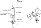
- Described here is also a device for extruding a membrane system including a hollow fiber membrane and a static mixer separately arranged within the hollow portion of the hollow fiber membrane, wherein the device includes the above spinneret.
- the device includes a motor for moving the first outlet opening around the outlet axis of the spinneret.
- the device includes a motor and a hollow shaft defining a flow path for a polymer solution for forming the static mixer (polymer solution (a)), wherein the first outlet opening is an opening of the hollow shaft and the hollow shaft is movable around the outlet axis and fluidically connected to a reservoir for the static mixer polymer solution (a), wherein the reservoir is also part of the device.
- the device includes a gear box which couples the motor to the hollow shaft.
- the motor is preferably a stepper motor.
- the connection between the reservoir for the polymer solution (a) and the hollow shaft is preferably established by a rotation coupling which connects to the hollow shaft such that the rotational movement of the hollow shaft is decoupled from the reservoir for polymer solution (a).
- a connector such as tubing may be comprised by the device in order to fluidically connect the rotation coupling to the reservoir.
- the present invention relates to a method for forming a membrane system including a hollow fiber membrane and a static mixer arranged within the hollow portion of the hollow fiber membrane, comprising the steps (i) providing the above spinneret; (ii) providing a polymer solution (a) for forming the static mixer; (iii) providing a bore solution (b); (iv) providing a polymer solution (c) for forming the hollow fiber membrane; (v) extruding the polymer solution (a) for forming the static mixer through the first opening, extruding the bore solution (b) through the second opening, extruding the polymer solution (c) for forming the hollow fiber membrane through the third opening to form a jet of the solutions (a), (b) and (c); (vi) moving the first opening around the outlet axis for at least a part of the duration of step (v); (vii) immersing the jet into a coagulation bath; to coagulate the hollow fiber membrane and the static mixer.
- the immersing comprising the above
- the hollow fiber membrane and the static mixer are formed simultaneously by extruding polymer solutions (a) and (c) as well as the bore solution (b) through the spinneret according to the present invention.
- the inventive method By employing the method of the present invention, it is possible to form the membrane system according to the present invention wherein the hollow fiber membrane has an inner diameter of at most 10 mm.
- the inventive method also enables the manufacture of membrane systems having larger inner diameters.
- step (i) of the inventive method the above-described spinneret is provided.
- the above explanations regarding said spinneret also apply to the method according to the present invention.
- step (i) not only the spinneret but the above device including the spinneret is provided.
- the polymer solution (a) for forming the static mixer is provided.
- the polymer solution (a) is of the same type as a conventional polymer solution for forming a hollow fiber membrane e.g. by temperature induced phase separation (TIPS) and/or non-solvent induced phase separation (NIPS).
- TIPS temperature induced phase separation
- NIPS non-solvent induced phase separation
- polymer solution (a) applies to polymer solution (c) for forming the hollow fiber membrane which is provided in step (iv) of the method according to the present invention.
- Each of polymer solution (a) and polymer solution (c) is a membrane-forming polymer solution.
- a membrane-forming solution contains at least one membrane-forming polymer and at least one solvent.
- Suitable polymers to be included in polymer solutions (a) and (c) include, but are not limited to, PVDF, PAN, PTFE, PP, PE, PSU, PES/PESU, PAES, as already explained above in the context of the membrane system according to the present invention.
- PVDF PVDF
- PAN PTFE
- PP PE
- PE PE
- PSU PES/PESU
- PAES PAES
- Polymer solutions (a) and (c) may have the same or different compositions. Specifically, the polymer included in solution (a) may be different from the polymer included in solution (c). Each of polymer solutions (a) and (c) may contain one of more different polymers. According to a preferred embodiment of the present invention, polymer solutions (a) and (c) are constituted by the same components but may have different concentrations of the said components. In particular, in view of the minute structure of the static mixer, it is preferred that the polymer solution (a) has a lower solid content/a higher solvent content than the polymer solution (c). Thereby, a lower viscosity of the polymer solution (a) can be achieved, which facilitates the production of the static mixer in the method according to the present invention.
- the hollow fiber membrane and the static mixer can be coagulated by TIPS and/or by NIPS.
- Typical membrane forming polymers for TIPS include but are not limited to PVDF, PAN, PTFE, PP and PE, wherein PVDF and PAN are also suited for a combination of TIPS and NIPS.
- Typical membrane forming polymers for NIPS (or a combination of NIPS and TIPS) include but are not limited to, PSU, PES/PESU, PAES, PVDF and PAN.
- Each of the solutions (a) and (c) includes at least one solvent.
- the at least one solvent is selected such that a solution can be formed of the respective at least one membrane-forming polymer.
- the at least one solvent preferably includes an organic solvent such as N-methyl-2-pyrrolidone (NMP), dimethylformamide (DMF), dimethylacetamide (DMAc), dimethylsulfoxide (DMSO), tetrahydrofuran (THF), wherein NMP and DMSO are preferred.
- NMP N-methyl-2-pyrrolidone
- DMF dimethylformamide
- DMAc dimethylacetamide
- DMSO dimethylsulfoxide
- THF tetrahydrofuran
- water may be contained as a non-solvent.
- the water is deionized water.
- the weight ratio of water to organic solvent in polymer solutions (a) and (c) is preferably 0 to 20%, more preferably 0 to 15%, even more preferably 1 to 15%, particularly preferably
- the polymer solutions (a) and (c) may contain a pore-forming additive.
- Suitable pore-forming additives are known to the skilled person.
- the pore-forming additive may be a polymer that does not form a membrane (non-membrane-forming polymer) such as polyvinylpyrrolidone (PVP), polyethyleneglycol (PEG), polyoxazoline, polypropylene glycol, polyglycolmonoester, a copolymer of polyethyleneglycol with polypropylene glycol, a water-soluble cellulose derivative, polysorbate, polyethylene-polypropylene oxide copolymer, polyethyleneimine, and combinations thereof.
- PVP polyvinylpyrrolidone
- PEG polyethyleneglycol
- polyoxazoline polypropylene glycol
- polyglycolmonoester polyoxazoline
- polypropylene glycol polyglycolmonoester
- pore-forming additives that can be used in solutions (a) and/or (c) are glycerol and lithium chloride.
- Preferred pore-forming additives are PVP K30 and PVP K90.
- K30 and K90 indicates that the PVP has a K-value of 30 and 90, respectively.
- the K-value is commonly used for characterizing polymers and directly relates to the average molecular mass of the polymer. The K-value can be taken as an indicator for the degree of polymerization and the polymer chain length.
- the bore solution (b) provided in step (iii) of the method according to the present invention is not particularly limited as long as it induces coagulation/precipitation of the membrane-forming polymer solutions (a) and (c).
- the bore solution contains a non-solvent for the membrane forming polymer, for instance water.
- the bore solution (b) further contains the same constituents as the polymer solutions (a) and (c), except for the membrane-forming polymer.
- the bore solution (b) may also contain constituents different from the ones of the solutions (a) and (c).
- the bore solution (b) contains an organic solvent such as NMP and deionized water.
- the weight ratio of water to organic solvent in the bore solution (b) is 20 to 100%, preferably 40 to 60%.
- the bore solution (b) may contain a non-membrane-forming polymer such as polyvinylpyrrolidone (PVP), polyethyleneglycol (PEG), glycerol, polyoxazoline, polypropylene glycol, polyglycolmonoester, a copolymer of polyethyleneglycol with polypropylene glycol, a water-soluble cellulose derivative, polysorbate, polyethylene-polypropylene oxide copolymer, polyethyleneimine, and combinations thereof.
- PVP polyvinylpyrrolidone
- PEG polyethyleneglycol
- glycerol polyoxazoline
- polypropylene glycol polyglycolmonoester
- copolymer of polyethyleneglycol with polypropylene glycol a water-soluble
- PVP is preferred, even more preferred are PVP K30 and K90.
- the non-membrane-forming polymer can be added in order to adjust the viscosity of the bore solution and/or for controlling the speed of coagulation.
- PVP e.g. PVP K30 or PVP K90
- the content of the non-membrane-forming polymer in the bore solution (b) is preferably 0 to 12 wt%, more preferably 1 to 10 wt%, particularly preferably 2 to 7 wt%.
- At least one of the polymer solution (a), the bore solution (b), the polymer solution (c) and the coagulation bath contains the particles (B) at least at the time of step (vii).
- the particles (B) are contained in the polymer solution at the time of step (vii) or before, the particles (B) will be substantially evenly distributed over the entire volume of the membrane system. In case the particles (B) are contained in the coagulation bath and/or the bore solution at the time of step (vii) or before, the particles (B) will be present on at least one surface of the hollow fiber membrane and/or the static mixer. It is preferred that the particles (B) are contained in the polymer solution (a) and/or (c) at the time of step (vii) or before. It is particularly preferred that the particles (B) are contained in the polymer solution for forming the static mixer at the time of step (vii) or before.
- step (v) of the method according to the present invention a jet of the solutions (a), (b) and (c) is extruded by employing the spinneret described above.
- the polymer solution (a) for forming the static mixer is extruded through the first opening of the spinneret
- the bore solution (b) is extruded through the second opening of the spinneret
- the polymer solution (c) for forming the hollow fiber membrane is extruded through the third opening of the spinneret.
- Solutions (a) to (c) are extruded through the respective first, second and third opening at the same time (simultaneously).
- the flow rate of the bore solution (b) in step (v) is 1 to 250 ml/min, preferably 2 to 150 ml/min, more preferably 5 to 50 ml/min, for example 7 ml/min.
- the flow rate (extrusion rate) of polymer solution (c) in step (v) is preferably 1 to 250 g/min, more preferably 2 to 150 g/min, particularly preferably 5 to 50 g/min, for example 7.5 g/min.
- the flow rate of polymer solution (a) is preferably 0.5 to 150 g/min, more preferably 1 to 50 g/min, particularly preferably 2 to 30 g/min, for instance 3.5 g/min.
- the method for forming a membrane system includes a step (vi) of moving the first opening around the outer axis for at least a part of the duration of step (v).
- the rotational movement of the first opening results in a static mixer that includes sections that have the shape of a twisted ribbon.
- the first opening is moved (rotated) around the outlet axis at 50 to 5000 rotations/minute, preferably 70 to 1000 rotations/minutes, more preferably 100 to 500 rotations per minute, for example 280 rotations/minutes.
- the rotation speed of the first opening By changing the rotation speed of the first opening, the length of a 180°-twist of the twisted ribbon shape of the static mixer can be adjusted (see Figure 5 ).
- the first opening is moved around the outlet axis for the entire duration of step (v); or (vi") the first opening is moved around the outlet axis for a part of the duration of step (v).
- the entirety of the static mixer has the shape of a twisted ribbon.
- step (vi) only one of more sections of the static mixer has/have the shape of a twisted ribbon, whereas the other sections of the static mixer have the form of a planar ribbon (i.e. a plate shape).
- the rotation direction of the first opening may be changed so that the static mixer may include sections having the shape of a twisted ribbon, wherein the outer edges of the twisted ribbon define an ⁇ - or a ⁇ -double helix.
- step (vii) of the method for forming a membrane system according to the present invention the jet of the solutions (a), (b) and (c) is immersed into a coagulation bath; to coagulate the hollow fiber membrane and the static mixer.
- the jet is exposed to conditions which result in the coagulation of the hollow fiber membrane as well as the static mixer.
- the coagulation of step (vii) is carried out by temperature induced phase separation (TIPS), by non-solvent induced phase separation (NIPS) or by a combination of TIPS and NIPS.
- TIPS temperature induced phase separation
- NIPS non-solvent induced phase separation
- the coagulation bath has a temperature that is different from the temperature of the jet. Due to the temperature difference, the polymers (a) and (c) are coagulated (precipitated).
- step (vii) includes NIPS
- the coagulation bath has a composition that results in coagulation of the hollow fiber membrane and the static mixer.
- the coagulation bath may include a solvent composition that represents a non-solvent for the polymers of solutions (a) and (c).
- the jet of solutions (a) to (c) may be directly immersed into the coagulation bath, i.e. without any gap between the spinneret and the coagulation bath.
- the gap may be absent (i.e. the gap may have a width of 0 cm)
- the gap preferably has a width of more than 0 cm, more preferably at least 5 cm, particularly preferably at least 15 cm.
- the gap width is preferably not longer than 150 cm, more preferably not longer than 50 cm.
- the method for forming a membrane system according to the present invention further includes a step of (viii) separating (removing) the coagulated hollow fiber membrane and static mixer (membrane system) from the coagulation bath. Subsequent to said step (viii), a step of (ix) immersing the coagulated hollow fiber membrane into a rinsing bath may be carried out. By virtue of said step (ix), the coagulated hollow fiber membrane and static mixture are rinsed (washed) so that components of solutions (a), (b) and (c) which are undesired in the membrane system can be removed.
- step (x') immersing the hollow fiber membrane and the static mixer (membrane system) into a collection bath can be carried out subsequent to step (viii) or optionally step (ix).
- the membrane system can be (x") collected on a collection drum.
- the respective composition of the coagulation bath, the rinsing bath and the collection bath is not particularly limited and may include a solvent or solvent composition.
- a solvent or solvent composition an organic solvent and/or water may be used.
- the coagulation bath has a composition and/or temperature that results in precipitation/coagulation of the membrane system.
- the coagulation bath, the rinsing bath and the collection bath each consist of deionized water.
- step (vii) and optionally steps (viii) to (x') are carried out by dragging the coagulated hollow fiber membrane and static mixer by means of a pulling wheel.
- the pulling wheel pulls the coagulated hollow fiber membrane and static mixer (membrane system) at a speed of 0.1 to 40 m/min, more preferably 0.5 to 20 m/min, particularly preferably 0.7 to 7 m/min, for example 1.5 m/min.
- Another possibility for manufacturing the membrane system including the particles (B) is post-modifying the membrane system that does not yet have the particles (B).
- the present invention is further illustrated based on the following Example without being limited thereto.
- a membrane system including a hollow fiber membrane and a static mixer was produced under the following experimental conditions.
- compositions of polymer solutions (a), (b) and (c)
- NMP N-Methyl-2-pyrrolidone
- PVP K30 Polyvinylpyrrolidone
- PVP K30 Polyvinylpyrrolidone
Landscapes
- Chemical & Material Sciences (AREA)
- Chemical Kinetics & Catalysis (AREA)
- Dispersion Chemistry (AREA)
- Separation Using Semi-Permeable Membranes (AREA)
Claims (6)
- Verfahren zur Bildung eines Membransystems, das eine Hohlfasermembran und einen statischen Mischer umfasst, der innerhalb des hohlen Abschnitts der Hohlfasermembran angeordnet ist, umfassend die Schritte(i) Bereitstellen einer Spinndüse mit einer ersten Auslassöffnung, einer zweiten Auslassöffnung und einer dritten Auslassöffnung, wobeidie erste Auslassöffnung auf einer Auslassachse der Spinndüse angeordnet ist, eine längliche Querschnittsform aufweist und um die Auslassachse beweglich ist; die zweite Auslassöffnung um die erste Auslassöffnung herum und innerhalb des Umfangs der dritten Auslassöffnung angeordnet ist; unddie dritte Auslassöffnung um die erste Auslassöffnung und um den Umfang der zweiten Auslassöffnung herum angeordnet ist;(ii) Bereitstellen einer Polymerlösung (a) zur Bildung des statischen Mischers;(iii) Bereitstellen einer Bohrlösung (b);(iv) Bereitstellen einer Polymerlösung (c) zur Bildung der Hohlfasermembran;(v) Extrudieren der Polymerlösung (a) zur Bildung des statischen Mischers durch die erste Öffnung, Extrudieren der Bohrlösung (b) durch die zweite Öffnung, Extrudieren der Polymerlösung (c) zur Bildung der Hohlfasermembran durch die dritte Öffnung, um einen Strahl der Lösungen (a), (b) und (c) bilden;(vi) Bewegen der ersten Öffnung um die Auslassachse für mindestens einen Teil der Dauer von Schritt (v);(vii) Eintauchen des Strahls in ein Koagulationsbad;
zum Koagulieren der Hohlfasermembran und des statischen Mischers. - Verfahren nach Anspruch 1,
wobei die Polymerlösungen (a) und (c) unabhängig voneinander ein oder mehrere Polymere umfassen, ausgewählt aus der Gruppe, bestehend aus Polyvinylidenfluorid (PVDF), Polyacrylnitril (PAN), Polypropylen (PP), Polyethylen (PE), Polysulfon (PSU), Polyethersulfon (PES/PESU), Polyarylethersulfon (PAES), Polyamid (PA) und Polyphenylenoxid (PPO). - Verfahren nach Anspruch 1 oder 2, wobei(vi') die erste Öffnung während der gesamten Dauer von Schritt (v) um die Auslassachse bewegt wird; oder(vi") die erste Öffnung für einen Teil der Dauer von Schritt (v) um die Auslassachse bewegt wird.
- Verfahren nach einem der Ansprüche 1 bis 3, wobei
die erste Öffnung mit 50 bis 5000 Umdrehungen/Minute um die Auslassachse bewegt wird. - Verfahren nach einem der Ansprüche 1 bis 4, wobei
die Koagulation von Schritt (vii) durch temperaturinduzierte Phasentrennung (TIPS) und/oder durch nicht-lösungsmittelinduzierte Phasentrennung (NIPS) erfolgt. - Verfahren nach einem der Ansprüche 1 bis 5, weiter umfassend einen Schritt
(viii) Trennen der koagulierten Hohlfasermembran und des statischen Mischers von dem Koagulationsbad.
Applications Claiming Priority (2)
| Application Number | Priority Date | Filing Date | Title |
|---|---|---|---|
| EP19203629.1A EP3808435A1 (de) | 2019-10-16 | 2019-10-16 | Membransystem, spinndüse zur herstellung des membransystems, vorrichtung mit der spinndüse und verfahren zur herstellung des membransystems |
| PCT/EP2020/078923 WO2021074235A1 (en) | 2019-10-16 | 2020-10-14 | Membrane system, spinneret for manufacturing the membrane system, device including the spinneret and method for forming the membrane system |
Publications (3)
| Publication Number | Publication Date |
|---|---|
| EP3866957A1 EP3866957A1 (de) | 2021-08-25 |
| EP3866957C0 EP3866957C0 (de) | 2024-07-24 |
| EP3866957B1 true EP3866957B1 (de) | 2024-07-24 |
Family
ID=68281211
Family Applications (2)
| Application Number | Title | Priority Date | Filing Date |
|---|---|---|---|
| EP19203629.1A Withdrawn EP3808435A1 (de) | 2019-10-16 | 2019-10-16 | Membransystem, spinndüse zur herstellung des membransystems, vorrichtung mit der spinndüse und verfahren zur herstellung des membransystems |
| EP20788825.6A Active EP3866957B1 (de) | 2019-10-16 | 2020-10-14 | Verfahren zur herstellung des membransystems |
Family Applications Before (1)
| Application Number | Title | Priority Date | Filing Date |
|---|---|---|---|
| EP19203629.1A Withdrawn EP3808435A1 (de) | 2019-10-16 | 2019-10-16 | Membransystem, spinndüse zur herstellung des membransystems, vorrichtung mit der spinndüse und verfahren zur herstellung des membransystems |
Country Status (4)
| Country | Link |
|---|---|
| EP (2) | EP3808435A1 (de) |
| KR (1) | KR102552301B1 (de) |
| CN (1) | CN113423489B (de) |
| WO (1) | WO2021074235A1 (de) |
Families Citing this family (1)
| Publication number | Priority date | Publication date | Assignee | Title |
|---|---|---|---|---|
| WO2016123708A1 (en) | 2015-02-03 | 2016-08-11 | Christou Peter James | Tubular membrane with spiral flow |
Family Cites Families (11)
| Publication number | Priority date | Publication date | Assignee | Title |
|---|---|---|---|---|
| EP0048730A1 (de) * | 1980-03-24 | 1982-04-07 | Baxter Travenol Laboratories, Inc. | Diffusionsvorrichtung mit röhrenförmige strömungsleiter enthaltenden kanälen |
| JPS6118404A (ja) * | 1984-07-04 | 1986-01-27 | Teijin Ltd | 中空糸膜及びその製造方法 |
| DE69322776T2 (de) * | 1992-05-06 | 1999-08-05 | Costar Corp., Cambridge, Mass. | Verfahren zur herstellung einer mikroporösen polyvinylidenfluorid-membran |
| GB9305788D0 (en) | 1993-03-19 | 1993-05-05 | Bellhouse Brian John | Filter |
| KR100485620B1 (ko) * | 2002-01-15 | 2005-04-27 | 주식회사 파라 | 보강용 지지체를 가진 중공사막, 그 제조방법 및 이를제조하기 위한 방사구금 |
| EP1469929A4 (de) * | 2002-01-29 | 2005-09-07 | Amersham Biosciences Membrane | Hohlfasermembrane mit gewundener oberfläche |
| FR3024663B1 (fr) * | 2014-08-11 | 2020-05-08 | Technologies Avancees Et Membranes Industrielles | Nouvelles geometries d'elements tubulaires monocanaux de separation par flux tangentiel integrant des promoteurs de turbulences et procede de fabrication |
| WO2016178835A1 (en) * | 2015-05-01 | 2016-11-10 | Sabic Global Technologies B.V. | Method for making porous asymmetric membranes and associated membranes and separation modules |
| KR102139208B1 (ko) * | 2016-06-27 | 2020-07-29 | 한국화학연구원 | 내오염성 중공사막의 제조방법 및 상기 방법으로 제조된 내오염성 중공사막 |
| DE102016224627A1 (de) * | 2016-12-09 | 2018-06-14 | Fresenius Medical Care Deutschland Gmbh | Hohlfasermembran mit verbesserter Trennleistung und Herstellung einer Hohlfasermembran mit verbesserter Trennleistung |
| WO2018235210A1 (ja) * | 2017-06-21 | 2018-12-27 | エム・テクニック株式会社 | ろ過膜モジュール及びろ過処理方法 |
-
2019
- 2019-10-16 EP EP19203629.1A patent/EP3808435A1/de not_active Withdrawn
-
2020
- 2020-10-14 WO PCT/EP2020/078923 patent/WO2021074235A1/en not_active Ceased
- 2020-10-14 EP EP20788825.6A patent/EP3866957B1/de active Active
- 2020-10-14 KR KR1020217015877A patent/KR102552301B1/ko active Active
- 2020-10-14 CN CN202080013852.8A patent/CN113423489B/zh active Active
Also Published As
| Publication number | Publication date |
|---|---|
| KR20210091184A (ko) | 2021-07-21 |
| EP3866957C0 (de) | 2024-07-24 |
| CN113423489B (zh) | 2023-07-04 |
| EP3866957A1 (de) | 2021-08-25 |
| KR102552301B1 (ko) | 2023-07-06 |
| CN113423489A (zh) | 2021-09-21 |
| WO2021074235A1 (en) | 2021-04-22 |
| EP3808435A1 (de) | 2021-04-21 |
Similar Documents
| Publication | Publication Date | Title |
|---|---|---|
| AU2002213293B2 (en) | Hydrophilic hollow fiber ultrafiltration membranes that include a hydrophobic polymer and a method of making these membranes | |
| CN103619449B (zh) | 加压中空纤维膜组件 | |
| KR101217070B1 (ko) | 폴리머 섬유체, 그 제조 방법 및 유체 여과용 필터 | |
| CN103816818B (zh) | 一种超亲水梯度孔中空纤维膜及其制备方法 | |
| WO2002102500A1 (en) | Membrane polymer compositions | |
| EP1098691A1 (de) | Anti-mikrobielle semipermeable membran | |
| JP2020090766A (ja) | 多孔質繊維、吸着材料及び浄化カラム | |
| US20240278185A1 (en) | Composite hollow fiber and related methods and products | |
| CN101721925B (zh) | 家用净水中空纤维超滤膜的制备方法 | |
| EP3866957B1 (de) | Verfahren zur herstellung des membransystems | |
| CN111282455B (zh) | 外压式中空纤维工业纳滤膜及制备方法 | |
| US20010047959A1 (en) | Polyacrylonitrile-based filtration membrane in a hollow fiber state | |
| CN101500695A (zh) | 氟树脂聚合物分离膜及其制备方法 | |
| JP3594946B2 (ja) | 高性能精密濾過膜 | |
| JP3464000B1 (ja) | 高性能中空糸状精密濾過膜の製造方法 | |
| JP7764989B1 (ja) | 中空糸膜、中空糸膜モジュール、浄水器用カートリッジおよび浄水器 | |
| KR102800965B1 (ko) | 바이러스 제거용 폴리술폰계 고분자 중공사막의 제조방법 | |
| JP6959329B2 (ja) | 正荷電膜の製造のための方法 | |
| JP2020171923A (ja) | 多孔質膜 | |
| Nagashima et al. | Preparation and characterization of microporous hollow fiber membranes containing hydrotalcite as an inorganic adsorbent | |
| CN108554189B (zh) | 一种原位自组装聚合物纳米粒子增强分离膜及其制备方法 | |
| JPH0722690B2 (ja) | 芳香族ポリスルホン中空糸膜およびその製法 | |
| EP2004748A1 (de) | Hohlfasermembran und herstellungsverfahren dafür | |
| MARUYAMA et al. | Ryohichi NAGASHIMA", Satoshi YAHAGI", Haruko HIROSE" Yoshikage OHMUKAI" |
Legal Events
| Date | Code | Title | Description |
|---|---|---|---|
| STAA | Information on the status of an ep patent application or granted ep patent |
Free format text: STATUS: UNKNOWN |
|
| STAA | Information on the status of an ep patent application or granted ep patent |
Free format text: STATUS: THE INTERNATIONAL PUBLICATION HAS BEEN MADE |
|
| PUAI | Public reference made under article 153(3) epc to a published international application that has entered the european phase |
Free format text: ORIGINAL CODE: 0009012 |
|
| STAA | Information on the status of an ep patent application or granted ep patent |
Free format text: STATUS: REQUEST FOR EXAMINATION WAS MADE |
|
| 17P | Request for examination filed |
Effective date: 20210520 |
|
| AK | Designated contracting states |
Kind code of ref document: A1 Designated state(s): AL AT BE BG CH CY CZ DE DK EE ES FI FR GB GR HR HU IE IS IT LI LT LU LV MC MK MT NL NO PL PT RO RS SE SI SK SM TR |
|
| DAV | Request for validation of the european patent (deleted) | ||
| DAX | Request for extension of the european patent (deleted) | ||
| GRAP | Despatch of communication of intention to grant a patent |
Free format text: ORIGINAL CODE: EPIDOSNIGR1 |
|
| STAA | Information on the status of an ep patent application or granted ep patent |
Free format text: STATUS: GRANT OF PATENT IS INTENDED |
|
| INTG | Intention to grant announced |
Effective date: 20240325 |
|
| GRAS | Grant fee paid |
Free format text: ORIGINAL CODE: EPIDOSNIGR3 |
|
| GRAA | (expected) grant |
Free format text: ORIGINAL CODE: 0009210 |
|
| STAA | Information on the status of an ep patent application or granted ep patent |
Free format text: STATUS: THE PATENT HAS BEEN GRANTED |
|
| AK | Designated contracting states |
Kind code of ref document: B1 Designated state(s): AL AT BE BG CH CY CZ DE DK EE ES FI FR GB GR HR HU IE IS IT LI LT LU LV MC MK MT NL NO PL PT RO RS SE SI SK SM TR |
|
| REG | Reference to a national code |
Ref country code: GB Ref legal event code: FG4D |
|
| REG | Reference to a national code |
Ref country code: CH Ref legal event code: EP |
|
| REG | Reference to a national code |
Ref country code: IE Ref legal event code: FG4D Ref country code: DE Ref legal event code: R096 Ref document number: 602020034543 Country of ref document: DE |
|
| U01 | Request for unitary effect filed |
Effective date: 20240731 |
|
| U07 | Unitary effect registered |
Designated state(s): AT BE BG DE DK EE FI FR IT LT LU LV MT NL PT SE SI Effective date: 20240820 |
|
| U20 | Renewal fee for the european patent with unitary effect paid |
Year of fee payment: 5 Effective date: 20241028 |
|
| PG25 | Lapsed in a contracting state [announced via postgrant information from national office to epo] |
Ref country code: NO Free format text: LAPSE BECAUSE OF FAILURE TO SUBMIT A TRANSLATION OF THE DESCRIPTION OR TO PAY THE FEE WITHIN THE PRESCRIBED TIME-LIMIT Effective date: 20241024 |
|
| PG25 | Lapsed in a contracting state [announced via postgrant information from national office to epo] |
Ref country code: PL Free format text: LAPSE BECAUSE OF FAILURE TO SUBMIT A TRANSLATION OF THE DESCRIPTION OR TO PAY THE FEE WITHIN THE PRESCRIBED TIME-LIMIT Effective date: 20240724 Ref country code: GR Free format text: LAPSE BECAUSE OF FAILURE TO SUBMIT A TRANSLATION OF THE DESCRIPTION OR TO PAY THE FEE WITHIN THE PRESCRIBED TIME-LIMIT Effective date: 20241025 |
|
| PG25 | Lapsed in a contracting state [announced via postgrant information from national office to epo] |
Ref country code: IS Free format text: LAPSE BECAUSE OF FAILURE TO SUBMIT A TRANSLATION OF THE DESCRIPTION OR TO PAY THE FEE WITHIN THE PRESCRIBED TIME-LIMIT Effective date: 20241124 |
|
| PG25 | Lapsed in a contracting state [announced via postgrant information from national office to epo] |
Ref country code: HR Free format text: LAPSE BECAUSE OF FAILURE TO SUBMIT A TRANSLATION OF THE DESCRIPTION OR TO PAY THE FEE WITHIN THE PRESCRIBED TIME-LIMIT Effective date: 20240724 |
|
| PG25 | Lapsed in a contracting state [announced via postgrant information from national office to epo] |
Ref country code: RS Free format text: LAPSE BECAUSE OF FAILURE TO SUBMIT A TRANSLATION OF THE DESCRIPTION OR TO PAY THE FEE WITHIN THE PRESCRIBED TIME-LIMIT Effective date: 20241024 Ref country code: ES Free format text: LAPSE BECAUSE OF FAILURE TO SUBMIT A TRANSLATION OF THE DESCRIPTION OR TO PAY THE FEE WITHIN THE PRESCRIBED TIME-LIMIT Effective date: 20240724 |
|
| PG25 | Lapsed in a contracting state [announced via postgrant information from national office to epo] |
Ref country code: RS Free format text: LAPSE BECAUSE OF FAILURE TO SUBMIT A TRANSLATION OF THE DESCRIPTION OR TO PAY THE FEE WITHIN THE PRESCRIBED TIME-LIMIT Effective date: 20241024 Ref country code: PL Free format text: LAPSE BECAUSE OF FAILURE TO SUBMIT A TRANSLATION OF THE DESCRIPTION OR TO PAY THE FEE WITHIN THE PRESCRIBED TIME-LIMIT Effective date: 20240724 Ref country code: NO Free format text: LAPSE BECAUSE OF FAILURE TO SUBMIT A TRANSLATION OF THE DESCRIPTION OR TO PAY THE FEE WITHIN THE PRESCRIBED TIME-LIMIT Effective date: 20241024 Ref country code: IS Free format text: LAPSE BECAUSE OF FAILURE TO SUBMIT A TRANSLATION OF THE DESCRIPTION OR TO PAY THE FEE WITHIN THE PRESCRIBED TIME-LIMIT Effective date: 20241124 Ref country code: HR Free format text: LAPSE BECAUSE OF FAILURE TO SUBMIT A TRANSLATION OF THE DESCRIPTION OR TO PAY THE FEE WITHIN THE PRESCRIBED TIME-LIMIT Effective date: 20240724 Ref country code: GR Free format text: LAPSE BECAUSE OF FAILURE TO SUBMIT A TRANSLATION OF THE DESCRIPTION OR TO PAY THE FEE WITHIN THE PRESCRIBED TIME-LIMIT Effective date: 20241025 Ref country code: ES Free format text: LAPSE BECAUSE OF FAILURE TO SUBMIT A TRANSLATION OF THE DESCRIPTION OR TO PAY THE FEE WITHIN THE PRESCRIBED TIME-LIMIT Effective date: 20240724 |
|
| PG25 | Lapsed in a contracting state [announced via postgrant information from national office to epo] |
Ref country code: RO Free format text: LAPSE BECAUSE OF FAILURE TO SUBMIT A TRANSLATION OF THE DESCRIPTION OR TO PAY THE FEE WITHIN THE PRESCRIBED TIME-LIMIT Effective date: 20240724 Ref country code: SM Free format text: LAPSE BECAUSE OF FAILURE TO SUBMIT A TRANSLATION OF THE DESCRIPTION OR TO PAY THE FEE WITHIN THE PRESCRIBED TIME-LIMIT Effective date: 20240724 |
|
| PG25 | Lapsed in a contracting state [announced via postgrant information from national office to epo] |
Ref country code: CZ Free format text: LAPSE BECAUSE OF FAILURE TO SUBMIT A TRANSLATION OF THE DESCRIPTION OR TO PAY THE FEE WITHIN THE PRESCRIBED TIME-LIMIT Effective date: 20240724 |
|
| PG25 | Lapsed in a contracting state [announced via postgrant information from national office to epo] |
Ref country code: SK Free format text: LAPSE BECAUSE OF FAILURE TO SUBMIT A TRANSLATION OF THE DESCRIPTION OR TO PAY THE FEE WITHIN THE PRESCRIBED TIME-LIMIT Effective date: 20240724 |
|
| PLBE | No opposition filed within time limit |
Free format text: ORIGINAL CODE: 0009261 |
|
| STAA | Information on the status of an ep patent application or granted ep patent |
Free format text: STATUS: NO OPPOSITION FILED WITHIN TIME LIMIT |
|
| REG | Reference to a national code |
Ref country code: CH Ref legal event code: PL |
|
| GBPC | Gb: european patent ceased through non-payment of renewal fee |
Effective date: 20241024 |
|
| 26N | No opposition filed |
Effective date: 20250425 |
|
| PG25 | Lapsed in a contracting state [announced via postgrant information from national office to epo] |
Ref country code: MC Free format text: LAPSE BECAUSE OF FAILURE TO SUBMIT A TRANSLATION OF THE DESCRIPTION OR TO PAY THE FEE WITHIN THE PRESCRIBED TIME-LIMIT Effective date: 20240724 |
|
| PG25 | Lapsed in a contracting state [announced via postgrant information from national office to epo] |
Ref country code: GB Free format text: LAPSE BECAUSE OF NON-PAYMENT OF DUE FEES Effective date: 20241024 |
|
| PG25 | Lapsed in a contracting state [announced via postgrant information from national office to epo] |
Ref country code: CH Free format text: LAPSE BECAUSE OF NON-PAYMENT OF DUE FEES Effective date: 20241031 |
|
| PG25 | Lapsed in a contracting state [announced via postgrant information from national office to epo] |
Ref country code: IE Free format text: LAPSE BECAUSE OF NON-PAYMENT OF DUE FEES Effective date: 20241014 |
|
| U20 | Renewal fee for the european patent with unitary effect paid |
Year of fee payment: 6 Effective date: 20251029 |
|
| PG25 | Lapsed in a contracting state [announced via postgrant information from national office to epo] |
Ref country code: CY Free format text: LAPSE BECAUSE OF FAILURE TO SUBMIT A TRANSLATION OF THE DESCRIPTION OR TO PAY THE FEE WITHIN THE PRESCRIBED TIME-LIMIT; INVALID AB INITIO Effective date: 20201014 |
|
| PG25 | Lapsed in a contracting state [announced via postgrant information from national office to epo] |
Ref country code: HU Free format text: LAPSE BECAUSE OF FAILURE TO SUBMIT A TRANSLATION OF THE DESCRIPTION OR TO PAY THE FEE WITHIN THE PRESCRIBED TIME-LIMIT; INVALID AB INITIO Effective date: 20201014 |