EP3866277A1 - Winkelstecker mit einem entlang einer gekrümmten bahn verschiebbaren modul - Google Patents
Winkelstecker mit einem entlang einer gekrümmten bahn verschiebbaren modul Download PDFInfo
- Publication number
- EP3866277A1 EP3866277A1 EP20157319.3A EP20157319A EP3866277A1 EP 3866277 A1 EP3866277 A1 EP 3866277A1 EP 20157319 A EP20157319 A EP 20157319A EP 3866277 A1 EP3866277 A1 EP 3866277A1
- Authority
- EP
- European Patent Office
- Prior art keywords
- holding module
- terminal holding
- housing
- connector according
- terminal
- Prior art date
- Legal status (The legal status is an assumption and is not a legal conclusion. Google has not performed a legal analysis and makes no representation as to the accuracy of the status listed.)
- Withdrawn
Links
- 230000013011 mating Effects 0.000 claims abstract description 4
- 230000000903 blocking effect Effects 0.000 claims description 6
- 238000003780 insertion Methods 0.000 claims description 2
- 230000037431 insertion Effects 0.000 claims description 2
- 238000000034 method Methods 0.000 description 3
- 238000007789 sealing Methods 0.000 description 3
- 238000002788 crimping Methods 0.000 description 2
- 239000003989 dielectric material Substances 0.000 description 2
- 239000000654 additive Substances 0.000 description 1
- 230000000996 additive effect Effects 0.000 description 1
- 230000001419 dependent effect Effects 0.000 description 1
- 239000002991 molded plastic Substances 0.000 description 1
Images

Classifications
-
- H—ELECTRICITY
- H01—ELECTRIC ELEMENTS
- H01R—ELECTRICALLY-CONDUCTIVE CONNECTIONS; STRUCTURAL ASSOCIATIONS OF A PLURALITY OF MUTUALLY-INSULATED ELECTRICAL CONNECTING ELEMENTS; COUPLING DEVICES; CURRENT COLLECTORS
- H01R13/00—Details of coupling devices of the kinds covered by groups H01R12/70 or H01R24/00 - H01R33/00
- H01R13/46—Bases; Cases
- H01R13/516—Means for holding or embracing insulating body, e.g. casing, hoods
-
- H—ELECTRICITY
- H01—ELECTRIC ELEMENTS
- H01R—ELECTRICALLY-CONDUCTIVE CONNECTIONS; STRUCTURAL ASSOCIATIONS OF A PLURALITY OF MUTUALLY-INSULATED ELECTRICAL CONNECTING ELEMENTS; COUPLING DEVICES; CURRENT COLLECTORS
- H01R13/00—Details of coupling devices of the kinds covered by groups H01R12/70 or H01R24/00 - H01R33/00
- H01R13/62—Means for facilitating engagement or disengagement of coupling parts or for holding them in engagement
- H01R13/629—Additional means for facilitating engagement or disengagement of coupling parts, e.g. aligning or guiding means, levers, gas pressure electrical locking indicators, manufacturing tolerances
-
- H—ELECTRICITY
- H01—ELECTRIC ELEMENTS
- H01R—ELECTRICALLY-CONDUCTIVE CONNECTIONS; STRUCTURAL ASSOCIATIONS OF A PLURALITY OF MUTUALLY-INSULATED ELECTRICAL CONNECTING ELEMENTS; COUPLING DEVICES; CURRENT COLLECTORS
- H01R13/00—Details of coupling devices of the kinds covered by groups H01R12/70 or H01R24/00 - H01R33/00
- H01R13/40—Securing contact members in or to a base or case; Insulating of contact members
-
- H—ELECTRICITY
- H01—ELECTRIC ELEMENTS
- H01R—ELECTRICALLY-CONDUCTIVE CONNECTIONS; STRUCTURAL ASSOCIATIONS OF A PLURALITY OF MUTUALLY-INSULATED ELECTRICAL CONNECTING ELEMENTS; COUPLING DEVICES; CURRENT COLLECTORS
- H01R13/00—Details of coupling devices of the kinds covered by groups H01R12/70 or H01R24/00 - H01R33/00
- H01R13/46—Bases; Cases
- H01R13/502—Bases; Cases composed of different pieces
-
- H—ELECTRICITY
- H01—ELECTRIC ELEMENTS
- H01R—ELECTRICALLY-CONDUCTIVE CONNECTIONS; STRUCTURAL ASSOCIATIONS OF A PLURALITY OF MUTUALLY-INSULATED ELECTRICAL CONNECTING ELEMENTS; COUPLING DEVICES; CURRENT COLLECTORS
- H01R13/00—Details of coupling devices of the kinds covered by groups H01R12/70 or H01R24/00 - H01R33/00
- H01R13/46—Bases; Cases
- H01R13/52—Dustproof, splashproof, drip-proof, waterproof, or flameproof cases
- H01R13/5205—Sealing means between cable and housing, e.g. grommet
-
- H—ELECTRICITY
- H01—ELECTRIC ELEMENTS
- H01R—ELECTRICALLY-CONDUCTIVE CONNECTIONS; STRUCTURAL ASSOCIATIONS OF A PLURALITY OF MUTUALLY-INSULATED ELECTRICAL CONNECTING ELEMENTS; COUPLING DEVICES; CURRENT COLLECTORS
- H01R13/00—Details of coupling devices of the kinds covered by groups H01R12/70 or H01R24/00 - H01R33/00
- H01R13/62—Means for facilitating engagement or disengagement of coupling parts or for holding them in engagement
- H01R13/639—Additional means for holding or locking coupling parts together, after engagement, e.g. separate keylock, retainer strap
-
- H—ELECTRICITY
- H01—ELECTRIC ELEMENTS
- H01R—ELECTRICALLY-CONDUCTIVE CONNECTIONS; STRUCTURAL ASSOCIATIONS OF A PLURALITY OF MUTUALLY-INSULATED ELECTRICAL CONNECTING ELEMENTS; COUPLING DEVICES; CURRENT COLLECTORS
- H01R13/00—Details of coupling devices of the kinds covered by groups H01R12/70 or H01R24/00 - H01R33/00
- H01R13/46—Bases; Cases
- H01R13/502—Bases; Cases composed of different pieces
- H01R13/506—Bases; Cases composed of different pieces assembled by snap action of the parts
-
- H—ELECTRICITY
- H01—ELECTRIC ELEMENTS
- H01R—ELECTRICALLY-CONDUCTIVE CONNECTIONS; STRUCTURAL ASSOCIATIONS OF A PLURALITY OF MUTUALLY-INSULATED ELECTRICAL CONNECTING ELEMENTS; COUPLING DEVICES; CURRENT COLLECTORS
- H01R2201/00—Connectors or connections adapted for particular applications
- H01R2201/26—Connectors or connections adapted for particular applications for vehicles
Definitions
- This disclosure generally relates to the field of automotive connections. More particularly this disclosure relates to non-straight or angled connectors, such as right-angle connectors for example.
- non-straight or angled connectors such as right-angle connectors for example.
- power connectors is taken as an example, but the person skilled in the art will easily understand how to transpose this disclosure to any kind of angled connectors.
- connectors In the connector field, at least two types of connectors are commonly used: straight connectors and angled connectors, such as right-angle connectors.
- the assembly of angled connectors may be more complex than the assembly of straight-connectors, in particular when angled terminals are used. Indeed, terminals must be accommodated in individual cavities insulated from one another by dielectric material. Further, the connection of the wires to the terminals, for example by crimping, can be carried out by harness makers while the final assembly of the connector can be carried out by another supplier or manufacturer. It then becomes difficult to insert the terminals in the connector housing. As a consequence, the assembly processes can be complex and costly.
- This disclosure aims at contributing to provide versatile assembly processes of angled connectors. This aim is at least partially achieved with a connector according to claim 1.
- the use of a terminal holding module allows connecting wires to terminals prior to the insertion of the terminals in the terminal holding module, and prior to the mounting of the terminal holding module in the housing. Consequently, the terminal holding module can be prepared with (typically) basic standard straight terminals and wires by a harness maker, while the final mounting of the terminal holding module in the housing can be made by another manufacturer.
- FIG. 1 An example of connector 1 is shown on FIG. 1 .
- This connector 1 is a right-angled connector for connecting power cables 2 to a socket connector 3.
- HVIL High Voltage Interlock Line
- this connector 1 comprises two power terminals (not shown), each respectively connected to a power cable 2, and two HVIL terminals 4 connected to the HVIL line.
- the connector 1 further comprises an outer housing 5 and an inner housing 6 ( FIG. 2 ), as well as electromagnetic shields and a mating assist mechanism 7.
- the general architecture of such a connector 1 is described for example in the patent document US9059540B2 which is incorporated by reference.
- the inner housing 6 of the connector 1 is made of a dielectric material.
- the inner housing 6 is made of moulded plastic.
- the inner housing 6 has two lateral cavities 8 for accommodating power terminals and a central cavity 9 for accommodating a terminal holding module 10 (See FIG. 3 ). More precisely, the terminal holding module 10 houses HVIL terminals 4 (See FIGS. 6A to 6D ).
- the inner housing 6 has a general right-angled shape.
- the central cavity 9 has a rear portion 11 (See FIGS. 6A to 6D ) extending in a first direction D and a front portion 12 extending in a second direction E which is orthogonal to the first direction D.
- the rear portion 11 has a rear opening 13 which is widely open.
- the front portion 12 has several front openings 14, one of which is configured to receive a counterpart connector comprised in the socket connector 3, to be mated with the HVIL terminals 4 accommodated in the terminal holding module 10.
- the rear portion 11 is a straight portion extending in the first direction D
- the front portion 12 is a straight portion extending in the second direction E and there is a curved portion 15 between the rear 11 and the front 12 portions.
- the central cavity 9 is thus configured to allow the terminal holding module 10 to be guided through the rear portion 11, the curved portion 15 and then finally the front portion 12 where it assumes its operation position.
- the inner housing 6 comprises guiding features 16 for guiding the terminal holding module 10 in the inner housing 6 from the rear opening 13 where it is first inserted, towards its operation position.
- the guiding features 16 have a generally curved shape. More particularly, the guiding features 16 have straight paths each corresponding respectively to the rear 11 and front 12 portions, as well as a curved path in between. These paths are defined by two upper rails 17 and a lower floor 18.
- the terminal holding module 10 comprises a first part 19 and a second part 20.
- the first part 19 has two pins 21 protruding on respective opposite lateral faces 22 and engaging in two corresponding openings 23 of the second part 20.
- the pins 21 extend parallel to a rotation axis A.
- the first part 19 is rotatable about this rotation axis A relative to the second part 20.
- the terminal holding module 10 also comprises temporary blocking means 24.
- this blocking means 24 comprises two bumps 25 on the first part 19, and two holes 26 in the second part 20.
- the bumps 25 protrude on respective opposite lateral faces 22 and engage in a corresponding hole 26 of the second part 20.
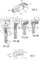
- the temporary blocking means 24 maintains aligned the first part 19 and the second part 20 while the terminal holding module 10 is inserted in the inner housing 6 (See FIG.6A ).
- the bumps 25 are forced out of the holes 26 and the first 19 and second 20 parts can rotate relative to each other about the rotation axis A.
- the guiding features 16 comprises a step 36 for tilting the first part 19 relative to the second part 20 (See FIG. 6B ), forcing the first part 19 and the second part 20 to be released from the blocking means 24.
- the first part 19 comprises two cavities 27 for accommodating each respectively an HVIL terminal 4 (basically a straight terminal).
- Each HVIL terminal 4 is electrically connected, for example by crimping, to an HVIL electrical wire 28.
- An HVIL terminal 4 extends in a straight direction in each one of the cavities 27.
- the HVIL electrical wires 28 extend out of the first part 19, in the second part 20.
- the HVIL electrical wires 28 remain flexible and free to move in the inner housing 6 between the first 19 and second 20 parts so as to accompany the rotation of the first part 19 relative to the second part 20 (See FIG. 6B to FIG. 6D ).
- the first part 19 has a protrusion 29 extending toward the lower floor 18.
- This protrusion 29 helps wedge the terminal holding module 10 in the inner housing 6, when the terminal holding module 10 is in its final operation position. Indeed, for rotating the first part 19 in the curved portion, the first part 19 cannot be as large as the curved portion. However, in its operation position, the terminal holding module 10 has to be tightly maintained in the inner module 6. Then the protrusion 29 wedges the terminal holding module 10 in its front region and the second part 20 pushes the rear region of the terminal holding module 10.
- the second part 20 comprises two cavities 30 through which the HVIL electrical wires 28 are guided.
- a single wire seal (SWS) is placed in each one of these cavities 30, for providing a sealing between each HVIL electrical wire 28 and the second part 20.
- An additive flat seal (not shown) covering both the HVIL terminal holding module 10 and the inner housing 6 can complete the sealing.
- the second part 20 also comprises a prehension area 21 (See FIG. 5 ) through which an operator can handle and push the terminal holding module 10 in the inner housing 6.
- the second part 20 comprises locking means 32 for locking the terminal holding module 10 in the inner housing 6, in its operation position.
- This locking means 32 comprises two beams 33 extending in an opening in respective opposite lateral faces of the second part 20, so as to provide some flexibility to the beams 33 (See FIG. 7 ).
- a tooth 34 is provided on each beam 33. Each tooth 34 protrudes from the lateral faces of the second part 20. When the terminal holding module 10 is in its operation position, each tooth 34 engages behind a stop 35 made on the inner housing 6 so as to lock the terminal holding module 10 in the inner housing 6.
- the connector assembly process comprises for example the following steps:
Landscapes
- Connector Housings Or Holding Contact Members (AREA)
- Details Of Connecting Devices For Male And Female Coupling (AREA)
Priority Applications (3)
| Application Number | Priority Date | Filing Date | Title |
|---|---|---|---|
| EP20157319.3A EP3866277A1 (de) | 2020-02-14 | 2020-02-14 | Winkelstecker mit einem entlang einer gekrümmten bahn verschiebbaren modul |
| US17/114,878 US20210257778A1 (en) | 2020-02-14 | 2020-12-08 | Angled connector with a module sliding along a curved path |
| CN202110013915.6A CN113270749A (zh) | 2020-02-14 | 2021-01-05 | 连接器 |
Applications Claiming Priority (1)
| Application Number | Priority Date | Filing Date | Title |
|---|---|---|---|
| EP20157319.3A EP3866277A1 (de) | 2020-02-14 | 2020-02-14 | Winkelstecker mit einem entlang einer gekrümmten bahn verschiebbaren modul |
Publications (1)
| Publication Number | Publication Date |
|---|---|
| EP3866277A1 true EP3866277A1 (de) | 2021-08-18 |
Family
ID=69593582
Family Applications (1)
| Application Number | Title | Priority Date | Filing Date |
|---|---|---|---|
| EP20157319.3A Withdrawn EP3866277A1 (de) | 2020-02-14 | 2020-02-14 | Winkelstecker mit einem entlang einer gekrümmten bahn verschiebbaren modul |
Country Status (3)
| Country | Link |
|---|---|
| US (1) | US20210257778A1 (de) |
| EP (1) | EP3866277A1 (de) |
| CN (1) | CN113270749A (de) |
Citations (4)
| Publication number | Priority date | Publication date | Assignee | Title |
|---|---|---|---|---|
| DE9101045U1 (de) * | 1991-01-30 | 1992-06-04 | Schaltbau Gmbh, 8000 Muenchen, De | |
| DE19805708A1 (de) * | 1998-02-12 | 1999-09-09 | Siemens Ag | Steckvorrichtung |
| US9059540B2 (en) | 2011-05-18 | 2015-06-16 | Delphi International Operations Luxembourg S.A.R.L. | Electrical connector assembly, and connector for such assembly |
| EP3584890A1 (de) * | 2018-06-18 | 2019-12-25 | Yazaki Corporation | Verbinder |
Family Cites Families (4)
| Publication number | Priority date | Publication date | Assignee | Title |
|---|---|---|---|---|
| EP0867978A3 (de) * | 1997-03-27 | 1999-06-16 | Siemens Aktiengesellschaft | Koaxialer Winkelsteckverbinder |
| CN101888049B (zh) * | 2010-06-21 | 2012-06-20 | 贵州航天电器股份有限公司 | 一种弯式射频三同轴电连接器 |
| US9257772B2 (en) * | 2013-02-08 | 2016-02-09 | Lear Corporation | Electric connector with a lock to retain a terminal within a housing |
| JP6730353B2 (ja) * | 2018-03-20 | 2020-07-29 | 矢崎総業株式会社 | コネクタ |
-
2020
- 2020-02-14 EP EP20157319.3A patent/EP3866277A1/de not_active Withdrawn
- 2020-12-08 US US17/114,878 patent/US20210257778A1/en not_active Abandoned
-
2021
- 2021-01-05 CN CN202110013915.6A patent/CN113270749A/zh active Pending
Patent Citations (4)
| Publication number | Priority date | Publication date | Assignee | Title |
|---|---|---|---|---|
| DE9101045U1 (de) * | 1991-01-30 | 1992-06-04 | Schaltbau Gmbh, 8000 Muenchen, De | |
| DE19805708A1 (de) * | 1998-02-12 | 1999-09-09 | Siemens Ag | Steckvorrichtung |
| US9059540B2 (en) | 2011-05-18 | 2015-06-16 | Delphi International Operations Luxembourg S.A.R.L. | Electrical connector assembly, and connector for such assembly |
| EP3584890A1 (de) * | 2018-06-18 | 2019-12-25 | Yazaki Corporation | Verbinder |
Also Published As
| Publication number | Publication date |
|---|---|
| US20210257778A1 (en) | 2021-08-19 |
| CN113270749A (zh) | 2021-08-17 |
Similar Documents
| Publication | Publication Date | Title |
|---|---|---|
| US10644416B2 (en) | Connector | |
| EP2686919B1 (de) | Hochspannungsverbinderanordnung | |
| CA2702928C (en) | Multi position electrical connector assembly | |
| CN108736198B (zh) | 连接器 | |
| CN108475889B (zh) | 大功率电连接器 | |
| CN101809822B (zh) | 具有冗余的端子锁定的连接器 | |
| EP1962390B1 (de) | Verbinder und Verbinderanordnung | |
| US9455523B1 (en) | Right angle connection assembly | |
| CN110690625B (zh) | 连接器装置 | |
| US20100317214A1 (en) | Electrical connector system with power and command connectors | |
| EP3709448A1 (de) | Endpositionssicherungselement mit mehreren verriegelungen | |
| US20150140846A1 (en) | Connector | |
| US5913691A (en) | Dual power/control connector | |
| JP6994880B2 (ja) | 回転可能なハウジングを有する電気ケーブルコネクタ | |
| US5820409A (en) | Rotatable pin connector | |
| US5823808A (en) | Cam lever operated connector | |
| US11489286B2 (en) | Electrical connector with a mate assist system | |
| EP3866277A1 (de) | Winkelstecker mit einem entlang einer gekrümmten bahn verschiebbaren modul | |
| US5934938A (en) | Split seal retainer for an electrical connector | |
| CN217215249U (zh) | 连接器组件和连接器模块的套件 | |
| US20220071040A1 (en) | Socket connector for a power connector system | |
| US10079445B2 (en) | Electrical connector for a twisted pair cable | |
| KR102550876B1 (ko) | 동축 케이블용 커넥터 | |
| JP2949488B2 (ja) | 電気コネクタ | |
| JP6688670B2 (ja) | コネクタ組立方法及びコネクタ |
Legal Events
| Date | Code | Title | Description |
|---|---|---|---|
| PUAI | Public reference made under article 153(3) epc to a published international application that has entered the european phase |
Free format text: ORIGINAL CODE: 0009012 |
|
| STAA | Information on the status of an ep patent application or granted ep patent |
Free format text: STATUS: THE APPLICATION HAS BEEN PUBLISHED |
|
| AK | Designated contracting states |
Kind code of ref document: A1 Designated state(s): AL AT BE BG CH CY CZ DE DK EE ES FI FR GB GR HR HU IE IS IT LI LT LU LV MC MK MT NL NO PL PT RO RS SE SI SK SM TR |
|
| STAA | Information on the status of an ep patent application or granted ep patent |
Free format text: STATUS: REQUEST FOR EXAMINATION WAS MADE |
|
| 17P | Request for examination filed |
Effective date: 20220216 |
|
| RBV | Designated contracting states (corrected) |
Designated state(s): AL AT BE BG CH CY CZ DE DK EE ES FI FR GB GR HR HU IE IS IT LI LT LU LV MC MK MT NL NO PL PT RO RS SE SI SK SM TR |
|
| RAP3 | Party data changed (applicant data changed or rights of an application transferred) |
Owner name: APTIV TECHNOLOGIES LIMITED |
|
| STAA | Information on the status of an ep patent application or granted ep patent |
Free format text: STATUS: THE APPLICATION IS DEEMED TO BE WITHDRAWN |
|
| 18D | Application deemed to be withdrawn |
Effective date: 20230901 |