EP3865949A1 - Hologram exposure machine and beam forming device for same - Google Patents
Hologram exposure machine and beam forming device for same Download PDFInfo
- Publication number
- EP3865949A1 EP3865949A1 EP21155711.1A EP21155711A EP3865949A1 EP 3865949 A1 EP3865949 A1 EP 3865949A1 EP 21155711 A EP21155711 A EP 21155711A EP 3865949 A1 EP3865949 A1 EP 3865949A1
- Authority
- EP
- European Patent Office
- Prior art keywords
- light
- shaping device
- beam shaping
- hologram
- wheel
- Prior art date
- Legal status (The legal status is an assumption and is not a legal conclusion. Google has not performed a legal analysis and makes no representation as to the accuracy of the status listed.)
- Pending
Links
- 238000007493 shaping process Methods 0.000 claims abstract description 36
- 230000010287 polarization Effects 0.000 description 25
- 230000001419 dependent effect Effects 0.000 description 9
- 210000002858 crystal cell Anatomy 0.000 description 8
- 239000004973 liquid crystal related substance Substances 0.000 description 8
- 229910052710 silicon Inorganic materials 0.000 description 8
- 239000010703 silicon Substances 0.000 description 8
- XUIMIQQOPSSXEZ-UHFFFAOYSA-N Silicon Chemical compound [Si] XUIMIQQOPSSXEZ-UHFFFAOYSA-N 0.000 description 6
- 238000000034 method Methods 0.000 description 4
- 230000001681 protective effect Effects 0.000 description 4
- 230000001427 coherent effect Effects 0.000 description 3
- 238000004519 manufacturing process Methods 0.000 description 3
- 239000000463 material Substances 0.000 description 3
- 230000003287 optical effect Effects 0.000 description 2
- 238000007664 blowing Methods 0.000 description 1
- 239000012876 carrier material Substances 0.000 description 1
- 230000002950 deficient Effects 0.000 description 1
- 238000011161 development Methods 0.000 description 1
- 230000018109 developmental process Effects 0.000 description 1
- 230000000694 effects Effects 0.000 description 1
- 239000011521 glass Substances 0.000 description 1
- 239000005337 ground glass Substances 0.000 description 1
- 239000007788 liquid Substances 0.000 description 1
- 229910052751 metal Inorganic materials 0.000 description 1
- 239000002184 metal Substances 0.000 description 1
- 150000002739 metals Chemical class 0.000 description 1
- 150000003376 silicon Chemical class 0.000 description 1
Images


Classifications
-
- G—PHYSICS
- G03—PHOTOGRAPHY; CINEMATOGRAPHY; ANALOGOUS TECHNIQUES USING WAVES OTHER THAN OPTICAL WAVES; ELECTROGRAPHY; HOLOGRAPHY
- G03H—HOLOGRAPHIC PROCESSES OR APPARATUS
- G03H1/00—Holographic processes or apparatus using light, infrared or ultraviolet waves for obtaining holograms or for obtaining an image from them; Details peculiar thereto
- G03H1/04—Processes or apparatus for producing holograms
- G03H1/20—Copying holograms by holographic, i.e. optical means
- G03H1/202—Contact copy when the reconstruction beam for the master H1 also serves as reference beam for the copy H2
-
- G—PHYSICS
- G02—OPTICS
- G02B—OPTICAL ELEMENTS, SYSTEMS OR APPARATUS
- G02B26/00—Optical devices or arrangements for the control of light using movable or deformable optical elements
- G02B26/08—Optical devices or arrangements for the control of light using movable or deformable optical elements for controlling the direction of light
- G02B26/10—Scanning systems
- G02B26/12—Scanning systems using multifaceted mirrors
- G02B26/121—Mechanical drive devices for polygonal mirrors
- G02B26/122—Control of the scanning speed of the polygonal mirror
-
- G—PHYSICS
- G02—OPTICS
- G02B—OPTICAL ELEMENTS, SYSTEMS OR APPARATUS
- G02B26/00—Optical devices or arrangements for the control of light using movable or deformable optical elements
- G02B26/08—Optical devices or arrangements for the control of light using movable or deformable optical elements for controlling the direction of light
- G02B26/10—Scanning systems
- G02B26/12—Scanning systems using multifaceted mirrors
- G02B26/129—Systems in which the scanning light beam is repeatedly reflected from the polygonal mirror
-
- G—PHYSICS
- G02—OPTICS
- G02B—OPTICAL ELEMENTS, SYSTEMS OR APPARATUS
- G02B27/00—Optical systems or apparatus not provided for by any of the groups G02B1/00 - G02B26/00, G02B30/00
- G02B27/0025—Optical systems or apparatus not provided for by any of the groups G02B1/00 - G02B26/00, G02B30/00 for optical correction, e.g. distorsion, aberration
- G02B27/0031—Optical systems or apparatus not provided for by any of the groups G02B1/00 - G02B26/00, G02B30/00 for optical correction, e.g. distorsion, aberration for scanning purposes
-
- G—PHYSICS
- G02—OPTICS
- G02B—OPTICAL ELEMENTS, SYSTEMS OR APPARATUS
- G02B27/00—Optical systems or apparatus not provided for by any of the groups G02B1/00 - G02B26/00, G02B30/00
- G02B27/09—Beam shaping, e.g. changing the cross-sectional area, not otherwise provided for
- G02B27/0933—Systems for active beam shaping by rapid movement of an element
-
- G—PHYSICS
- G02—OPTICS
- G02B—OPTICAL ELEMENTS, SYSTEMS OR APPARATUS
- G02B27/00—Optical systems or apparatus not provided for by any of the groups G02B1/00 - G02B26/00, G02B30/00
- G02B27/09—Beam shaping, e.g. changing the cross-sectional area, not otherwise provided for
- G02B27/0938—Using specific optical elements
- G02B27/0977—Reflective elements
-
- G—PHYSICS
- G03—PHOTOGRAPHY; CINEMATOGRAPHY; ANALOGOUS TECHNIQUES USING WAVES OTHER THAN OPTICAL WAVES; ELECTROGRAPHY; HOLOGRAPHY
- G03H—HOLOGRAPHIC PROCESSES OR APPARATUS
- G03H1/00—Holographic processes or apparatus using light, infrared or ultraviolet waves for obtaining holograms or for obtaining an image from them; Details peculiar thereto
- G03H1/02—Details of features involved during the holographic process; Replication of holograms without interference recording
-
- G—PHYSICS
- G03—PHOTOGRAPHY; CINEMATOGRAPHY; ANALOGOUS TECHNIQUES USING WAVES OTHER THAN OPTICAL WAVES; ELECTROGRAPHY; HOLOGRAPHY
- G03H—HOLOGRAPHIC PROCESSES OR APPARATUS
- G03H1/00—Holographic processes or apparatus using light, infrared or ultraviolet waves for obtaining holograms or for obtaining an image from them; Details peculiar thereto
- G03H1/0005—Adaptation of holography to specific applications
- G03H1/0011—Adaptation of holography to specific applications for security or authentication
-
- G—PHYSICS
- G03—PHOTOGRAPHY; CINEMATOGRAPHY; ANALOGOUS TECHNIQUES USING WAVES OTHER THAN OPTICAL WAVES; ELECTROGRAPHY; HOLOGRAPHY
- G03H—HOLOGRAPHIC PROCESSES OR APPARATUS
- G03H1/00—Holographic processes or apparatus using light, infrared or ultraviolet waves for obtaining holograms or for obtaining an image from them; Details peculiar thereto
- G03H1/02—Details of features involved during the holographic process; Replication of holograms without interference recording
- G03H1/024—Hologram nature or properties
- G03H1/0248—Volume holograms
-
- G—PHYSICS
- G03—PHOTOGRAPHY; CINEMATOGRAPHY; ANALOGOUS TECHNIQUES USING WAVES OTHER THAN OPTICAL WAVES; ELECTROGRAPHY; HOLOGRAPHY
- G03H—HOLOGRAPHIC PROCESSES OR APPARATUS
- G03H1/00—Holographic processes or apparatus using light, infrared or ultraviolet waves for obtaining holograms or for obtaining an image from them; Details peculiar thereto
- G03H1/04—Processes or apparatus for producing holograms
- G03H1/20—Copying holograms by holographic, i.e. optical means
- G03H2001/205—Subdivided copy, e.g. scanning transfer
-
- G—PHYSICS
- G03—PHOTOGRAPHY; CINEMATOGRAPHY; ANALOGOUS TECHNIQUES USING WAVES OTHER THAN OPTICAL WAVES; ELECTROGRAPHY; HOLOGRAPHY
- G03H—HOLOGRAPHIC PROCESSES OR APPARATUS
- G03H2222/00—Light sources or light beam properties
- G03H2222/35—Transverse intensity distribution of the light beam
-
- G—PHYSICS
- G03—PHOTOGRAPHY; CINEMATOGRAPHY; ANALOGOUS TECHNIQUES USING WAVES OTHER THAN OPTICAL WAVES; ELECTROGRAPHY; HOLOGRAPHY
- G03H—HOLOGRAPHIC PROCESSES OR APPARATUS
- G03H2222/00—Light sources or light beam properties
- G03H2222/36—Scanning light beam
-
- G—PHYSICS
- G03—PHOTOGRAPHY; CINEMATOGRAPHY; ANALOGOUS TECHNIQUES USING WAVES OTHER THAN OPTICAL WAVES; ELECTROGRAPHY; HOLOGRAPHY
- G03H—HOLOGRAPHIC PROCESSES OR APPARATUS
- G03H2223/00—Optical components
- G03H2223/17—Element having optical power
-
- G—PHYSICS
- G03—PHOTOGRAPHY; CINEMATOGRAPHY; ANALOGOUS TECHNIQUES USING WAVES OTHER THAN OPTICAL WAVES; ELECTROGRAPHY; HOLOGRAPHY
- G03H—HOLOGRAPHIC PROCESSES OR APPARATUS
- G03H2223/00—Optical components
- G03H2223/21—Anamorphic optical element, e.g. cylindrical
-
- G—PHYSICS
- G03—PHOTOGRAPHY; CINEMATOGRAPHY; ANALOGOUS TECHNIQUES USING WAVES OTHER THAN OPTICAL WAVES; ELECTROGRAPHY; HOLOGRAPHY
- G03H—HOLOGRAPHIC PROCESSES OR APPARATUS
- G03H2223/00—Optical components
- G03H2223/24—Reflector; Mirror
-
- G—PHYSICS
- G03—PHOTOGRAPHY; CINEMATOGRAPHY; ANALOGOUS TECHNIQUES USING WAVES OTHER THAN OPTICAL WAVES; ELECTROGRAPHY; HOLOGRAPHY
- G03H—HOLOGRAPHIC PROCESSES OR APPARATUS
- G03H2227/00—Mechanical components or mechanical aspects not otherwise provided for
- G03H2227/04—Production line for mass production
-
- G—PHYSICS
- G03—PHOTOGRAPHY; CINEMATOGRAPHY; ANALOGOUS TECHNIQUES USING WAVES OTHER THAN OPTICAL WAVES; ELECTROGRAPHY; HOLOGRAPHY
- G03H—HOLOGRAPHIC PROCESSES OR APPARATUS
- G03H2240/00—Hologram nature or properties
- G03H2240/50—Parameters or numerical values associated with holography, e.g. peel strength
- G03H2240/52—Exposure parameters, e.g. time, intensity
Definitions
- the invention relates to a beam shaping device for a hologram exposure machine and to a hologram exposure machine with such a device.
- holograms are entities which have at least one feature which makes unauthorized duplication, imitation and / or falsification of an object in which the security element is integrated more difficult.
- Holograms are used as security elements, for example in passports or identity cards. However, they are also used in banknotes, driver's licenses, visas, other stamps, labels or tickets, credit cards, bank cards, telephone cards or the like.
- Volume holograms represent a special group of holograms.
- a diffractive structure of the hologram is stored in the volume of the holographic recording material, such as, for example, the printed matter DE 10 2012 215 540 A1 , DE 10 2007 042 385 A1 and DE 10 2007 042 386 A1 can be found.
- holographic exposure films are used as recording materials for volume holograms in value and / or security documents, which are usually provided on rolls. These exposure films are suitable for creating interference structures store whose characteristic dimensions are in the range of the light wavelength of the light which is used for recording or reconstructing the hologram.
- the holographic exposure film is arranged in front of a master in which diffractive structures are formed which are to be "transferred” into the holographic exposure film.
- the diffractive structures of the master are thus copied into the holographic film during the contact copying process.
- coherent light is radiated onto the master through the holographic film, which is arranged in the immediate vicinity in front of the master or in contact with the master in front of it.
- the diffractive structures in the master diffract the light so that the diffracted light is reflected back into the holographic film. There it interferes with the coherent light that is used to illuminate the master.
- An interference structure is thus formed in the holographic film, which is defined by the light diffracted at the master.
- a hologram which is also referred to as a Denisjuk hologram and is a volume reflection hologram, is stored in the holographic film. It goes without saying that the irradiated light must have a suitable wavelength (or suitable wavelengths) and a suitable irradiation direction (or suitable irradiation directions) so that diffraction takes place in the desired manner at the diffraction structure.
- a method of making a master and a contact copying method are US Pat EP 0 896 260 A2 refer to.
- a beam-shaping device formed as a Powell or cylindrical lens.
- This beam shaping device expands the light emitted by the light source, as a rule, along a spatial direction in such a way that a scan line with a preferably homogeneous intensity distribution is present in order to expose the hologram.
- the cut of the Powell lenses can cause unwanted stripe effects in holograms, which are resulting from the tolerances resulting in the manufacture of the lenses. In the case of the widened line, intensity fluctuations occur along the line, which can lead to rejects during the exposure.
- the Powell lens and its beam shaping is very dependent on the incoming laser beam profile.
- the beam shaping device for the hologram exposure machine comprises at least one entry opening for light emitted by a light source. Furthermore, there is a wheel which has a base surface formed as a polygon, a cover surface corresponding to the base surface and a jacket surface which connects the base surface to the cover surface and is formed from mirrored rectangles.
- the beam shaping device also comprises an electric drive unit which is designed to drive the wheel in rotation about an axis of rotation oriented perpendicularly with respect to the direction of incidence of the light. There is also an exit opening for the light reflected from the jacket surface.
- a beam-shaping device formed with a polygon wheel is independent of the laser beam profile and, given sufficient rotation of the wheel, ensures a uniform intensity distribution of the light expanded by the beam-shaping device.
- the correction lens is designed as a converging lens (e.g. in the form of a cylindrical lens) for focusing the incident light beam on the outer surface of the wheel.
- a suitable widening, for example in only one spatial direction, can be brought about in that a cylindrical lens, which is preferably plano-convex, is also arranged in the outlet opening.
- the cylinder lens is designed in such a way that the light emerging from the exit opening has an intensity that is homogeneous across its dimensions.
- a homogeneous intensity is to be understood as the smallest possible, in particular non-measurable, intensity fluctuation.
- the rectangles forming the lateral surface have a width oriented perpendicularly with respect to the axis of rotation, which is smaller than the dimension of the cylindrical lens oriented perpendicularly with respect to the axis of rotation.
- a homogeneous intensity of the expanded light beam can be produced in that the drive unit is designed to drive the wheel with at least 1000 revolutions / per minute, with a drive of up to 12000 revolutions / per minute being preferred.
- the drive unit is preferably also designed to keep the number of revolutions constant.
- the polygon of the wheel is preferably also formed as a regular polygon, thus as a polygon.
- the width of the scan line depends on the dimensions of the exit opening and the cylindrical lens possibly arranged therein, it is sufficient if the incident light beam is only reflected in certain areas.
- the direction of incidence of the light and the at least one direction of emergence of the light reflected by the lateral surface are oriented perpendicularly and laterally offset to the axis of rotation of the wheel.
- a hologram exposure machine equipped with the beam shaping device according to the invention is distinguished by an improved quality of the hologram introduced into a hologram film. It is no longer dependent on the cut of the Powell lens, which is subject to manufacturing tolerances. For this reason, the advantages and advantageous configurations mentioned for the beam shaping device according to the invention apply to the same extent to the hologram exposure machine according to the invention.
- FIG. 1 A hologram exposure machine 300 for exposing holograms in a hologram film 200 is shown schematically. Such a hologram exposure machine 300 is also referred to as a holosetter.
- the hologram exposure machine 300 comprises an exposure device 302 shown at the top in the drawing and an exposure table 100 shown at the bottom in the drawing.
- the exposure device 302 has a light source 304, which in the present case is designed as a cw laser.
- cw stands for “continuous wave” and means “wave emitted constant over time”.
- the light source 304 is a pulsed laser.
- a plurality of light sources 304 can also be present, each of which emits a different wavelength of the light.
- the light 400 of the light source 304 embodied as a laser has a first polarization state. Beam guiding optics 306 are used to guide the light 400.
- the light from the light source 304 is initially guided to a deflection and scanning device 310 of the optical beam guidance system 306 with the aid of a beam shaping device 322 for beam expansion, in particular oriented in one spatial direction.
- This deflection and scanning device 310 comprises a galvanometer scanner which can be driven in rotation and a mirror 308 which is coupled to the galvanometer scanner and on which the incident light 400 is deflected.
- the mirror 308 In a first position, the mirror 308 is shown by means of a solid line, while it is shown in a second position with dashed lines.
- an exposure of the hologram corresponding to a “scan”, in particular a line scan can take place.
- the hologram film 200 is "scanned" to expose the hologram.
- Deflection and scanning devices 310 of different types for the light 400 can also be used.
- the deflected light 400 is guided onto a polarization-dependent beam splitter cube 312 of the optical beam guiding system 306.
- This is formed from a first prism and a second prism, at their interface a polarization-dependent one Beam splitting takes place.
- a beam splitter plate can also be used instead of prisms.
- Light 400 of the first polarization state is deflected at this interface.
- light of a further polarization state orthogonal to the first polarization state can pass through the interface.
- the light 400 deflected at the interface of the polarization-dependent beam splitter cube 312 is directed onto a spatial light modulator 314, which is designed as a so-called liquid crystal-on-silicon light modulator (LCoS).
- the light modulator 314 comprises a silicon layer 316 on which incident light 400 is reflected.
- electronic switching elements are formed on this silicon layer 316, which are used to switch liquid crystal cells 318, which are arranged in front of the surface of the silicon layer 316 used for reflection.
- the individual liquid crystal cells 318 can be put individually into different switching states.
- An array of liquid crystal cells 318 is typically present, so that further rows of liquid crystal cells 318 are present, offset from or into the plane of the paper.
- a polarization state of the light 400 passing through is changed or not changed, as a result of which the light 400 is spatially modulated.
- the light 400 impinging on the light modulator 314 in a first polarization state is changed overall in terms of polarization when it passes through a liquid crystal cell 318, which is passed through twice due to the reflection on the surface of the silicon layer 316 that the light 400 is then polarized in the further polarization state orthogonal to the first polarization state.
- This polarization-modulated light 400 passes through a transparent protective pane 320 of the spatial light modulator 314, in particular an exit surface of the protective pane 320 being oriented parallel to the reflective surface of the silicon layer 316.
- the surface normal of the light modulator 314 is thus orthogonal both to the exit surface of the protective pane 320 and to the reflective surface of the silicon layer 316.
- the modulated light After exiting the light modulator 314, the modulated light strikes the polarization-dependent beam splitter 312 again, and the modulated light 400 reflected back by the LCoS may or may not pass the interface of the beam splitter 312 depending on its polarization state. If the modulated light 400, as in the example shown, has been converted into the further polarization state orthogonal to the first polarization state due to the first switching state of the liquid crystal cell, it can pass the interface of the polarization-dependent beam splitter cube 312, whereby it can, if necessary, with the aid of a polarization filter 324, is passed further in the direction of the exposure table 100.
- Portions of the light 400 that are still in the first polarization state and arrive at the polarization-dependent beam splitter cube 312 are deflected at its interface and therefore do not travel further in the direction of the exposure table 100 located below the exposure device 302 the light 400 is thus spatially modulated in terms of intensity as a function of the modulated polarization state.
- the spatial light modulator 314 rotates the polarization state of the light by 90 degrees or leaves it unchanged.
- changes are also possible which cause a rotation of the polarization direction between 0 degrees and 90 degrees. All these rotations lead to the light having a changed amplitude and thus a changed intensity of the further polarization state.
- these vary and increase with the amount of rotation between 0 degrees and 90 degrees. This makes it possible to expose "gray levels".
- the exposure table 100 has a holding device 102 in which a master 104 is received.
- the master 104 comprises a carrier, which is usually formed from glass or another material. Other carrier materials are also possible, for example metals.
- At least one optically active layer for example a diffraction layer, which comprises a diffraction structure to be copied, is preferably applied to the carrier.
- the Diffraction layer of the master 104 is a volume reflection hologram to be copied.
- the exposure machine 300 in particular the exposure table 100, comprises a film transport device 106 which is designed to transport the hologram film 200 relative to the holding device 102 and thus relative to the master 104.
- the film transport device 106 is provided for picking up the holographic film and holding and / or guiding the film during the exposure of the hologram.
- the film transport device 106 comprises a film roll 110 on which the hologram film 200 is provided. After exposure, this is wound onto a further roll of film 118.
- the exposed hologram film 200 runs through a route for developing the holograms, through which the hologram film 200 is thermally acted upon in order to fix the hologram in the film before the exposed hologram film 200 is wound up again on the further film roll 118.
- the hologram film 200 is typically guided by means of film guide rollers. It can be seen that the hologram film 200 extends over the area of the master 104, so that the film transport device 106, in other words, is designed to position a film section 202 to be exposed relative to the master 104. The volume reflection hologram is exposed, and therefore copied, into this film section 202.
- the hologram film 200 lies against the master 104 during the exposure process. This system can suppress the holographic film's own movements, which increases the achievable diffraction efficiency of the hologram produced.
- the modulated light 400 which has the further polarization state, passes through the film section 202 of the hologram film 200 to be exposed and is deflected back at the optically active structure of the at least one optically active layer of the master 104, e.g. in the case of an optically designed as a diffraction layer active layer bent.
- the reflected light (not shown) then interferes in the hologram film 200 with the modulated light 400 coming from the light modulator 314.
- the optically active structure for example the diffractive structure, of the master 104 is exposed into the hologram film 200.
- the optically active structure is either exposed and copied pixel by pixel depending on the spatial modulation or, on the other hand, not exposed and therefore not copied either.
- a copy of the optically active structure is thus created, for example a copy of a volume reflection hologram of a ground glass.
- the holding device 102 is assigned a compressed air device 108 which is designed to fix the film section 202 at least temporarily by means of a negative pressure on the master 104 accommodated in the holding device 102.
- a slot which is arranged circumferentially around the master 104 and thus forms a gas passage arrangement 112.
- the gas passage arrangement 112 thus frames the master 104 on the circumferential side and thus ensures that the film section 202 to be exposed is in contact with the master 104 without bubbles of the master 104 is carried out supported by an air cushion, which additionally prevents damage to the hologram film 200.
- a wiper device 120 is also present in order to wipe the film section 202 to be exposed onto the master 104.
- this wiper device 120 is formed by a slide which can be displaced between two stops and on which a pressure roller is mounted which is rotatably mounted on an axis of rotation and which interacts with the film section 202 when it is wiped on.
- the present invention is concerned with the beam shaping device 322 for expanding the light emitted by the light source 304.
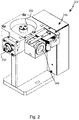
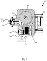
- a beam shaping device 322 is shown in FIG Figure 2 shown in more detail based on the section according to Figure 3 is explained in more detail.
- the beam shaping device 322 for the previously explained hologram exposure machine 300 comprises an entry opening 350 for the light 400 emitted by the light source 304 Cylindrical lens for focusing the incident light beam on a lateral surface 354 of a wheel 352 is formed.
- This wheel 352 has a base surface formed as a regular polygon (for example, polygon), a cover surface corresponding to the base surface and a jacket surface 354 which connects the base surface to the cover surface and is formed from mirrored rectangles.
- the wheel 352 is mounted rotatably about an axis of rotation, an electric drive unit 356 being present and designed to drive the wheel 352 in rotation about the axis of rotation oriented perpendicularly with respect to the direction of incidence of the light 400.
- an electric drive unit 356 being present and designed to drive the wheel 352 in rotation about the axis of rotation oriented perpendicularly with respect to the direction of incidence of the light 400.
- the light 400 reflected by the lateral surface 354 emerges from the beam shaping device 322 from an exit opening 358, into which a cylindrical lens 362 is introduced, which in the present case is designed as a plano-convex lens.
- a line 402 is produced by the cylinder lens 362, which is present quasistatically at a sufficient number of revolutions of the wheel 352.
- the drive unit 356 is designed in the present case to drive the wheel 352 with at least 1000 revolutions, in particular with 3000 to 5000 revolutions / min.
- the rectangles forming the lateral surface 354 have a width aligned perpendicularly with respect to the axis of rotation, which is smaller than the dimension of the cylindrical lens 362 aligned perpendicularly with respect to the axis of rotation the direction of incidence of the light 400 and the at least one direction of emergence of the reflected from the lateral surface 354
- Light 400 are aligned perpendicularly with respect to the axis of rotation of the wheel 352 and laterally offset to this.
- a line segment is caused by the beam-shaping device 322 by the rapid rotary movement of the wheel 352, which line segment has a quasi-homogeneous intensity distribution over its dimensions.
- the beam shaping device 322 formed in this way no longer has the disadvantages of using a Powell lens for beam expansion and is therefore particularly suitable for use in the hologram exposure machine 300.
- This hologram exposure machine 300 is characterized by a reliable exposure of holograms, so that the scrap rate, i.e. the number of defective holograms, is drastically reduced or reduced to a minimum.
Abstract
Die Erfindung betrifft eine Strahlformungseinrichtung (322) für eine Hologrammbelichtungsmaschine (300), mit mindestens einer Eintrittsöffnung (350) für von einer Lichtquelle (304) emittiertes Licht (400), mit einem Rad (352), das eine als ein Vieleck gebildete Grundfläche, eine der Grundfläche entsprechende Deckfläche sowie eine die Grundfläche mit der Deckfläche verbindende und aus verspiegelten Rechtecken gebildete Mantelfläche (354) aufweist, mit einer elektrischen Antriebseinheit (356), die ausgebildet ist, das Rad (352) um eine senkrecht bezüglich der Einfallsrichtung des Lichts (400) orientierte Drehachse rotatorisch anzutreiben, sowie mit einer Austrittsöffnung (358) für das von der Mantelfläche (354) reflektierte Licht (400). Die Erfindung betrifft außerdem eine Hologrammbelichtungsmaschine (300) mit einer solchen Strahlformungs-einrichtung (322).The invention relates to a beam shaping device (322) for a hologram exposure machine (300), with at least one inlet opening (350) for light (400) emitted by a light source (304), with a wheel (352) which has a base area formed as a polygon, has a top surface corresponding to the base surface and a jacket surface (354) which connects the base surface to the top surface and is formed from mirrored rectangles, with an electric drive unit (356) which is designed to move the wheel (352) around a perpendicular with respect to the direction of incidence of the light ( 400) oriented axis of rotation to drive rotationally, as well as with an exit opening (358) for the light (400) reflected from the lateral surface (354). The invention also relates to a hologram exposure machine (300) with such a beam shaping device (322).
Description
Die Erfindung betrifft eine Strahlformungseinrichtung für eine Hologrammbelichtungsmaschine sowie eine Hologrammbelichtungsmaschine mit einer solchen.The invention relates to a beam shaping device for a hologram exposure machine and to a hologram exposure machine with such a device.
Aus dem Stand der Technik ist es bekannt, Hologramme als Sicherheitselemente in Sicherheitsdokumente oder Wertdokumente zu integrieren. Sicherheitselemente sind solche Entitäten, welche mindestens ein Merkmal aufweisen, welches ein unautorisiertes Duplizieren, Nachahmen und/oder Verfälschen eines Gegenstands erschwert, in welchen das Sicherheitselement integriert ist. Hologramme werden als Sicherheitselemente beispielsweise in Reisepässen oder Personalausweisen verwendet. Sie werden jedoch auch in Banknoten, Führerscheinen, Visa, anderen Wertzeichen, Etiketten oder Tickets, Kreditkarten, Bankkarten, Telefonkarten oder Ähnlichem eingesetzt.It is known from the prior art to integrate holograms as security elements in security documents or documents of value. Security elements are entities which have at least one feature which makes unauthorized duplication, imitation and / or falsification of an object in which the security element is integrated more difficult. Holograms are used as security elements, for example in passports or identity cards. However, they are also used in banknotes, driver's licenses, visas, other stamps, labels or tickets, credit cards, bank cards, telephone cards or the like.
Eine besondere Gruppe von Hologrammen stellen Volumenhologramme dar. Bei einem Volumenhologramm ist eine beugende Struktur des Hologramms im Volumen des holografischen Aufzeichnungsmaterials gespeichert, wie beispielsweise den Druckschriften
Bei einem Kontaktkopierverfahren wird der holografische Belichtungsfilm vor einem Master angeordnet, in dem beugende Strukturen ausgebildet sind, die in den holografischen Belichtungsfilm "übertragen" werden sollen. Die beugenden Strukturen des Masters werden beim Kontaktkopierverfahren somit in den holografischen Film kopiert. Hierfür wird kohärentes Licht durch den holografischen Film, der in unmittelbarer Nähe vor dem Master oder in Kontakt mit dem Master vor diesem angeordnet ist, auf den Master gestrahlt. Die beugenden Strukturen in dem Master beugen das Licht so, dass das gebeugte Licht in den holografischen Film zurückgestrahlt wird. Dort interferiert dieses mit dem kohärenten Licht, welches zur Beleuchtung des Masters genutzt wird. In dem holografischen Film bildet sich somit eine Interferenzstruktur aus, welche durch das an dem Master gebeugte Licht festgelegt ist. Wird der holografische Film entwickelt und rekonstruiert, so gleicht die Rekonstruktion der, die beim Beleuchten des Masters zu beobachten ist. In dem holografischen Film wird ein Hologramm gespeichert, welches auch als Denisjuk-Hologramm bezeichnet wird und ein Volumenreflexionshologramm ist. Es versteht sich, dass das eingestrahlte Licht eine geeignete Wellenlänge (oder geeignete Wellenlängen) und eine geeignete Einstrahlrichtung (oder geeignete Einstrahlrichtungen) aufweisen muss, so dass eine Beugung an der Beugungsstruktur in der gewünschten Weise erfolgt. Ein Verfahren zur Herstellung eines Masters und ein Kontaktkopierverfahren sind der
Aus dem vorangehend zitierten Stand der Technik ist es bekannt, den Strahl der Lichtquelle aufzuweiten unter Verwendung einer als eine Powell- oder Zylinderlinse gebildeten Strahlformungseinrichtung. Diese Strahlformungseinrichtung weitet das von der Lichtquelle emittierte Licht in der Regel entlang einer Raumrichtung auf, derart, dass eine Scanlinie mit vorzugsweise homogener Intensitätsverteilung vorliegt, um das Hologramm zu belichten. Durch den Schliff der Powell-Linsen können unerwünschte Streifeneffekte in Hologramm hervorgerufen werden, die sich durch die bei der Fertigung der Linsen ergebenden Toleranzen ergeben. Bei der aufgeweiteten Linie treten also entlang der Linie Intensitätsschwankungen auf, die zu Ausschuss bei der Belichtung führen können. Die Powell-Linse und deren Strahlformung ist sehr vom eingehenden Laserstrahlprofil abhängig.From the prior art cited above, it is known to expand the beam of the light source using a beam-shaping device formed as a Powell or cylindrical lens. This beam shaping device expands the light emitted by the light source, as a rule, along a spatial direction in such a way that a scan line with a preferably homogeneous intensity distribution is present in order to expose the hologram. The cut of the Powell lenses can cause unwanted stripe effects in holograms, which are resulting from the tolerances resulting in the manufacture of the lenses. In the case of the widened line, intensity fluctuations occur along the line, which can lead to rejects during the exposure. The Powell lens and its beam shaping is very dependent on the incoming laser beam profile.
Es ist daher die Aufgabe der vorliegenden Erfindung, eine verbesserte Strahlformungseinrichtung und eine verbesserte Hologrammbelichtungsmaschine bereitzustellen.It is therefore the object of the present invention to provide an improved beam shaping device and an improved hologram exposure machine.
Diese Aufgabe wird gelöst durch eine Strahlformungseinrichtung mit den Merkmalen des Anspruchs 1 und durch eine Hologrammbelichtungsmaschine mit den Merkmalen des Anspruchs 10. Vorteilhafte Ausgestaltungen mit zweckmäßigen Weiterbildungen der Erfindung sind in den abhängigen Ansprüchen angegeben.This object is achieved by a beam shaping device with the features of claim 1 and by a hologram exposure machine with the features of claim 10. Advantageous configurations with expedient developments of the invention are specified in the dependent claims.
Die Strahlformungseinrichtung für die Hologrammbelichtungsmaschine umfasst dabei mindestens eine Eintrittsöffnung für von einer Lichtquelle emittiertes Licht. Ferner ist ein Rad vorhanden, das eine als ein Vieleck gebildete Grundfläche, eine der Grundfläche entsprechende Deckfläche sowie eine die Grundfläche mit der Deckfläche verbindende und aus verspiegelten Rechtecken gebildete Mantelfläche aufweist. Die Strahlformungseinrichtung umfasst außerdem eine elektrische Antriebseinheit, die ausgebildet ist, das Rad um eine senkrecht bezüglich der Einfallsrichtung des Lichts orientierte Drehachse rotatorisch anzutreiben. Ferner ist eine Austrittsöffnung vorhanden für das von der Mantelfläche reflektierte Licht. Eine mit einem Polygonrad geformte Strahlformungseinrichtung ist dabei unabhängig vom Laserstrahlprofil und gewährleistet bei hinreichender Umdrehung des Rades eine gleichmäßige Intensitätsverteilung des von der Strahlformungseinrichtung aufgeweiteten Lichts.The beam shaping device for the hologram exposure machine comprises at least one entry opening for light emitted by a light source. Furthermore, there is a wheel which has a base surface formed as a polygon, a cover surface corresponding to the base surface and a jacket surface which connects the base surface to the cover surface and is formed from mirrored rectangles. The beam shaping device also comprises an electric drive unit which is designed to drive the wheel in rotation about an axis of rotation oriented perpendicularly with respect to the direction of incidence of the light. There is also an exit opening for the light reflected from the jacket surface. A beam-shaping device formed with a polygon wheel is independent of the laser beam profile and, given sufficient rotation of the wheel, ensures a uniform intensity distribution of the light expanded by the beam-shaping device.
Um zu gewährleisten, dass das Laserstrahlprofil homogen und gleichmäßig auf die Mantelfläche des Rads auftrifft, hat es sich als sinnvoll erwiesen, wenn in die Eintrittsöffnung eine Korrekturlinse eingebracht ist.In order to ensure that the laser beam profile strikes the outer surface of the wheel homogeneously and uniformly, it has proven to be useful if a correction lens is introduced into the entry opening.
Zur Maximierung der Intensität des aufgeweiteten Lichtstrahls hat es sich zudem als vorteilhaft erwiesen, wenn die Korrekturlinse als eine Sammellinse (z. B. in Form einer Zylinderlinse) zur Fokussierung des einfallenden Lichtstrahls auf die Mantelfläche des Rads gebildet ist.In order to maximize the intensity of the expanded light beam, it has also proven to be advantageous if the correction lens is designed as a converging lens (e.g. in the form of a cylindrical lens) for focusing the incident light beam on the outer surface of the wheel.
Eine geeignete Aufweitung, beispielswese in lediglich einer Raumrichtung, lässt sich dadurch hervorrufen, dass auch in der Austrittsöffnung eine Zylinderlinse angeordnet ist, die vorzugsweise plankonvex vorliegt.A suitable widening, for example in only one spatial direction, can be brought about in that a cylindrical lens, which is preferably plano-convex, is also arranged in the outlet opening.
Da die meisten Hologrammbelichtungsmaschinen mit einem Linienscan belichten, hat es sich als sinnvoll erwiesen, wenn die Zylinderlinse ausgebildet ist, den Lichtstrahl auf eine Linie zu fokussieren; also eine gerade/ parallele Linie zu formen.Since most hologram exposure machines expose with a line scan, it has proven to be useful if the cylinder lens is designed to focus the light beam on a line; so to form a straight / parallel line.
In diesem Zusammenhang ist es zu dem von Vorteil, wenn die Zylinderlinse derart ausgestaltet ist, dass das aus der Austrittsöffnung austretende Licht eine über seine Abmessung hinweg homogene Intensität aufweist. Unter homogener Intensität ist eine möglichst geringe, insbesondere nicht messbare Intensitätsschwankung zu verstehen.In this context, it is also advantageous if the cylinder lens is designed in such a way that the light emerging from the exit opening has an intensity that is homogeneous across its dimensions. A homogeneous intensity is to be understood as the smallest possible, in particular non-measurable, intensity fluctuation.
Um die Vorrichtung entsprechend kompakt gestalten zu können, hat es sich als vorteilhaft erwiesen, wenn die die Mantelfläche bildenden Rechtecke eine senkrecht bezüglich der Drehachse ausgerichtete Breite aufweisen, die geringer ist als die senkrecht bezüglich der Drehachse ausgerichtete Abmessung der Zylinderlinse.In order to be able to make the device correspondingly compact, it has proven to be advantageous if the rectangles forming the lateral surface have a width oriented perpendicularly with respect to the axis of rotation, which is smaller than the dimension of the cylindrical lens oriented perpendicularly with respect to the axis of rotation.
Eine homogene Intensität des aufgeweiteten Lichtstrahls lässt sich dadurch hervorrufen, dass die Antriebseinheit ausgebildet ist, das Rad mit mindestens 1000 Umdrehungen/pro Minute anzutreiben, wobei ein Antreiben von bis zu 12000 Umdrehungen/pro Minute bevorzugt ist. In diesem Zusammenhang und um Intensitätsschwankungen zu vermeiden, ist vorzugsweise die Antriebseinheit zusätzlich ausgebildet, die Umdrehungsanzahl konstant zu halten. Aus diesem Grunde ist das Vieleck des Rades vorzugsweise auch als ein regelmäßiges Vieleck, mithin als ein Polygon gebildet.A homogeneous intensity of the expanded light beam can be produced in that the drive unit is designed to drive the wheel with at least 1000 revolutions / per minute, with a drive of up to 12000 revolutions / per minute being preferred. In this context and in order to avoid intensity fluctuations, the drive unit is preferably also designed to keep the number of revolutions constant. For this reason, the polygon of the wheel is preferably also formed as a regular polygon, thus as a polygon.
Da die Breite der Scanlinie abhängig ist von den Abmessungen der Austrittsöffnung sowie der darin gegebenenfalls angeordneten Zylinderlinse, genügt es, wenn eine Reflektion des einfallenden Lichtstrahls nur bereichsweise erfolgt. Um die Strahlformungseinrichtung kompakt zu halten ist es daher von Vorteil, dass die Einfallsrichtung des Lichts und die mindestens eine Ausfallsrichtung des von der Mantelfläche reflektierten Lichts senkrecht und seitlich versetzt zur Drehachse des Rads ausgerichtet sind.Since the width of the scan line depends on the dimensions of the exit opening and the cylindrical lens possibly arranged therein, it is sufficient if the incident light beam is only reflected in certain areas. In order to keep the beam shaping device compact, it is therefore advantageous that the direction of incidence of the light and the at least one direction of emergence of the light reflected by the lateral surface are oriented perpendicularly and laterally offset to the axis of rotation of the wheel.
Eine mit der erfindungsgemäßen Strahlformungseinrichtung ausgestattete Hologrammbelichtungsmaschine zeichnet sich durch eine verbesserte Qualität des in einen Hologrammfilm eingebrachten Hologramms aus. Sie ist nicht mehr abhängig von dem Fertigungstoleranzen unterliegenden Schliff der Powell-Linse. Aus diesem Grunde gelten die für die erfindungsgemäße Strahlformungseinrichtung genannten Vorteile und vorteilhaften Ausgestaltungen in gleichem Maße für die erfindungsgemäße Hologrammbelichtungsmaschine.A hologram exposure machine equipped with the beam shaping device according to the invention is distinguished by an improved quality of the hologram introduced into a hologram film. It is no longer dependent on the cut of the Powell lens, which is subject to manufacturing tolerances. For this reason, the advantages and advantageous configurations mentioned for the beam shaping device according to the invention apply to the same extent to the hologram exposure machine according to the invention.
Die vorliegende Erfindung wird nachfolgend anhand von Figuren näher erläutert, wobei die dargestellten Beispiele lediglich exemplarischen Charakter haben und keine Einschränkung hinsichtlich der Tragweite der beschriebenen Erfindung darstellen. Es zeigen im Einzelnen:
- Figur 1
- eine schematische Darstellung einer Hologrammbelichtungsmaschine zur Belichtung eines Volumenreflexionshologramms in einen Hologrammfilm,
- Figur 2
- eine perspektivische Ansicht einer Strahlformungseinrichtung,
- Figur 3
- eine Schnittansicht durch die Strahlformungseinrichtung nach
Figur 2 , und - Figur 4
- die Intensitätsverteilung der von der Strahlformungseinrichtung erzeugten Lichtlinie.
- Figure 1
- a schematic representation of a hologram exposure machine for exposing a volume reflection hologram in a hologram film,
- Figure 2
- a perspective view of a beam shaping device,
- Figure 3
- a sectional view through the beam shaping device according to
Figure 2 , and - Figure 4
- the intensity distribution of the light line generated by the beam shaping device.
In
Die Hologrammbelichtungsmaschine 300 umfasst eine in der Zeichnung oben dargestellte Belichtungseinrichtung 302 und einen in der Zeichnung unten dargestellten Belichtungstisch 100.The
Die Belichtung von Hologrammen erfolgt mittels kohärentem Licht. Hierfür weist die Belichtungeinrichtung 302 eine Lichtquelle 304 auf, welche vorliegend als ein cw-Laser ausgebildet ist. Vorliegend steht "cw" für "continuous wave" und bedeutet "zeitlich konstant abgestrahlte Welle". Es ist die Möglichkeit gegeben, dass es sich bei der Lichtquelle 304 um einen gepulsten Laser handelt. Es können auch mehrere Lichtquellen 304 vorhanden sein, die jeweils eine unterschiedliche Wellenlänge des Lichts emittieren. Das Licht 400 der als Laser ausgebildeten Lichtquelle 304 weist einen ersten Polarisationszustand auf. Zum Führen des Lichts 400 wird eine Strahlführungsoptik 306 verwendet. Das Licht der Lichtquelle 304 wird bei der dargestellten Belichtungseinrichtung 302 zunächst unter Zuhilfenahme einer Strahlformungseinrichtung 322 zur insbesondere in einer Raumrichtung orientierten Strahlaufweitung, auf eine Ablenk- und Scanvorrichtung 310 der Strahlführungsoptik 306 geführt. Diese Ablenk- und Scanvorrichtung 310 umfasst einen rotatorisch antreibbaren Galvanometerscanner und einen mit dem Galvanometerscanner gekoppelten Spiegel 308, an dem das einfallende Licht 400 umgelenkt wird. In einer ersten Stellung ist der Spiegel 308 mittels einer durchgezogenen Linie dargestellt, wobei er in einer zweiten Stellung strichliert gezeigt ist. Durch das Verschieben des Spiegels 308 kann eine einem "Scan", insbesondere einem Linienscan entsprechende Belichtung des Hologramms erfolgen. In anderen Worten wird der Hologrammfilm 200 zur Belichtung des Hologramms "abgetastet". Anders geartete Ablenk- und Scanvorrichtungen 310 für das Licht 400 sind ebenfalls einsetzbar.Holograms are exposed using coherent light. For this purpose, the
Das abgelenkte Licht 400 wird auf einen polarisationsabhängigen Strahlteilerwürfel 312 der Strahlführungsoptik 306 geführt. Dieser ist aus einem ersten Prisma und einem zweiten Prisma gebildet, an deren Grenzfläche eine polarisationsabhängige Strahlteilung erfolgt. Anstelle von Prismen kann auch eine Strahlteilerplatte Einsatz finden. Licht 400 des ersten Polarisationszustands wird an dieser Grenzfläche abgelenkt. Licht eines weiteren, zu dem ersten Polarisationszustand orthogonalen Polarisationszustands kann hingegen durch die Grenzfläche hindurchtreten.The deflected light 400 is guided onto a polarization-dependent beam splitter cube 312 of the optical beam guiding system 306. This is formed from a first prism and a second prism, at their interface a polarization-dependent one Beam splitting takes place. A beam splitter plate can also be used instead of prisms.
Das an der Grenzfläche des polarisationsabhängigen Strahlteilerwürfels 312 abgelenkte Licht 400 wird auf einen räumlichen Lichtmodulator 314 gelenkt, der als sogenannter Liquid-Crystal-on-Silicon-Lichtmodulator (LCoS) ausgebildet ist. Der Lichtmodulator 314 umfasst eine Siliziumschicht 316, an der auftreffendes Licht 400 reflektiert wird. Auf dieser Siliziumschicht 316 sind vorliegend elektronische Schaltelemente ausgebildet, die zum Schalten von Flüssigkristallzellen 318 verwendet werden, die vor der zur Reflexion genutzten Oberfläche der Siliziumschicht 316 angeordnet sind. Die einzelnen Flüssigkristallzellen 318 können individuell in unterschiedliche Schaltzustände versetzt werden. Typischerweise liegt ein Array an Flüssigkristallzellen 318 vor, so dass aus der Papierebene heraus oder in diese hinein versetzt weitere Reihen an Flüssigkristallzellen 318 vorliegen. Abhängig von dem jeweiligen Schaltzustand der Flüssigkristallzellen 318 wird ein Polarisationszustand des durchtretenden Lichts 400 geändert oder nicht geändert, wodurch das Licht 400 räumlich moduliert wird. Vereinfachend wird hier angenommen, dass in einem ersten Schaltzustand das in einem ersten Polarisationszustand auf den Lichtmodulator 314 auftreffende Licht 400 beim Durchtritt durch eine Flüssigkristallzelle 318, welche aufgrund der Reflexion an der Oberfläche der Siliziumschicht 316 zweimal durchlaufen wird, insgesamt hinsichtlich der Polarisation so verändert wird, dass das Licht 400 anschließend in dem zu dem ersten Polarisationszustand orthogonalen weiteren Polarisationszustand polarisiert ist. Dieses hinsichtlich der Polarisation modulierte Licht 400 tritt durch eine transparente Schutzscheibe 320 des räumlichen Lichtmodulators 314, wobei insbesondere eine Austrittsfläche der Schutzscheibe 320 parallel zu der Reflexionsoberfläche der Siliziumschicht 316 orientiert ist. Die Oberflächennormale des Lichtmodulators 314 ist somit orthogonal sowohl zu der Austrittsfläche der Schutzscheibe 320 als auch zu der reflektierenden Oberfläche der Siliziumschicht 316.The light 400 deflected at the interface of the polarization-dependent beam splitter cube 312 is directed onto a spatial
Das modulierte Licht trifft nach dem Austreten aus dem Lichtmodulator 314 erneut auf dem polarisationsabhängigen Strahlteiler 312 auf, wobei das vom LCoS zurückreflektierte modulierte Licht 400 abhängig von seinem Polarisationszustand die Grenzfläche des Strahlteilers 312 passieren kann oder nicht. Ist das modulierte Licht 400, wie im exemplarisch dargestellten Fall, aufgrund des ersten Schaltzustands der Flüssigkristallzelle in den zu dem ersten Polarisationszustand orthogonalen weiteren Polarisationszustand überführt worden, so kann dieses die Grenzfläche des polarisationsabhängigen Strahlteilerwürfels 312 passieren, womit es, ggfs. unter Zuhilfenahme eines Polarisationsfilters 324, weiter in Richtung des Belichtungstisches 100 geleitet wird. Anteile des Lichts 400, die sich nach wie vor in dem ersten Polarisationszustand befinden und an dem polarisationsabhängigen Strahlteilerwürfel 312 ankommen, werden an dessen Grenzfläche abgelenkt und gelangen daher nicht weiter in Richtung des sich unter der Belichtungseinrichtung 302 befindlichen Belichtungstisches 100. Durch den polarisationsabhängigen Strahlteilerwürfel 312 wird somit das Licht 400 abhängig von dem aufmodulierten Polarisationszustand räumlich hinsichtlich der Intensität moduliert.After exiting the
Bei der Beschreibung der Belichtungseinrichtung 302 wurde bis hierher davon ausgegangen, dass der räumliche Lichtmodulator 314 den Polarisationszustand des Lichts um 90 Grad dreht oder unverändert lässt. Es sind jedoch auch Änderungen möglich, die eine Drehung der Polarisationsrichtung zwischen 0 Grad und 90 Grad bewirken. Alle diese Drehungen führen dazu, dass das Licht eine veränderte Amplitude und damit veränderte Intensität des weiteren Polarisationszustands aufweist. Je nach Drehwinkel variieren diese und nehmen mit dem Betrag der Drehung zwischen 0 Grad und 90 Grad zu. Hierdurch ist es möglich "Graustufen" zu belichten.In the description of the
Der Belichtungstisch 100 weist eine Halteeinrichtung 102 auf, in welcher ein Master 104 aufgenommen ist. Der Master 104 umfasst einen Träger, welcher in der Regel aus Glas oder einem anderen Werkstoff gebildet ist. Auch andere Trägermaterialien sind möglich, beispielsweise Metalle. Auf den Träger ist vorzugsweise mindestens eine optisch aktive Schicht, beispielsweise eine Beugungsschicht, aufgebracht, welche eine zu kopierende Beugungsstruktur umfasst. Vorliegend umfasst die Beugungsschicht des Masters 104 ein Volumenreflexionshologramm, welches kopiert werden soll.The exposure table 100 has a holding device 102 in which a
Es ist zu erkennen, dass die Belichtungsmaschine 300, insbesondere der Belichtungstisch 100 eine Filmtransporteinrichtung 106 umfasst, die ausgebildet ist, den Hologrammfilm 200 relativ bezüglich der Halteeinrichtung 102 und damit relativ zum Master 104 zu transportieren. Die Filmtransporteinrichtung 106 ist für ein Aufnehmen des holografischen Films und Halten und/oder Führen des Films während der Belichtung des Hologramms vorgesehen. Bei der dargestellten Belichtungsmaschine 300 umfasst die Filmtransporteinrichtung 106 eine Filmrolle 110, auf der der Hologrammfilm 200 bereitgestellt wird. Dieser wird nach dem Belichten auf einer weiteren Filmrolle 118 aufgewickelt. Gegebenenfalls durchläuft der belichtete Hologrammfilm 200 eine Strecke zur Entwicklung der Hologramms, durch welche thermisch auf den Hologrammfilm 200 eingewirkt wird, um das Hologramm im Film zu fixieren, bevor der belichtete Hologrammfilm 200 auf der weiteren Filmrolle 118 wieder aufgewickelt wird. Der Hologrammfilm 200 wird jedenfalls in typischer Weise mittels Filmführungsrollen geführt. Es ist zu erkennen, dass sich der Hologrammfilm 200 über den Bereich des Masters 104 hinweg erstreckt, womit die Filmtransporteinrichtung 106 in anderen Worten also ausgebildet ist, einen zu belichtenden Filmabschnitt 202 relativ bezüglich des Masters 104 zu positionieren. In diesen Filmabschnitt 202 wird das Volumenreflexionshologramm belichtet, mithin einkopiert. Um eine betriebssichere Belichtung des Hologramms zu erzielen, liegt der Hologrammfilm 200 während des Belichtungsvorgangs an dem Master 104 an. Durch diese Anlage lassen sich Eigenbewegungen des holografischen Films unterdrücken, was die erzielbare Beugungseffizienz des hergestellten Hologramms steigert.It can be seen that the
Bei der Belichtung tritt das modulierte Licht 400, welches den weiteren Polarisationszustand aufweist, durch den zu belichtenden Filmabschnitt 202 des Hologrammfilms 200 hindurch und wird an der optisch aktiven Struktur der mindestens einen optisch aktiven Schicht des Masters 104 zurückgelenkt, z.B. bei einer als Beugungsschicht ausgebildeten optisch aktiven Schicht gebeugt. Das zurückgestrahlte Licht (nicht dargestellt) interferiert dann in dem Hologrammfilm 200 mit dem von dem Lichtmodulator 314 kommenden modulierten Licht 400. Hierdurch wird die optisch aktive Struktur, z.B. die beugende Struktur, des Masters 104 in den Hologrammfilm 200 einbelichtet. Hierbei wird die optisch aktive Struktur pixelweise abhängig von der räumlichen Modulation entweder belichtet und kopiert oder andererseits nicht belichtet und somit auch nicht kopiert. Es entsteht somit eine Kopie der optisch aktiven Struktur, beispielsweise eine Kopie eines Volumenreflexionshologramms einer Mattscheibe.During the exposure, the modulated
Der Halteeinrichtung 102 ist vorliegend eine Drucklufteinrichtung 108 zugeordnet, die ausgebildet ist, für die Belichtung des Filmabschnitts 202 diesen mittels eines Unterdrucks an dem in der Halteeinrichtung 102 aufgenommenen Master 104 zumindest zeitweise zu fixieren. Hierzu ist vorliegend ein um den Master 104 umfangsseitig angeordneter Schlitz vorhanden, der somit eine Gasdurchtrittsanordnung 112 bildet. Die Gasdurchtrittsanordnung 112 rahmt also den Master 104 umfangsseitig und gewährleistet damit ein blasenfreies Anliegen des zu belichtenden Filmabschnitts 202 am Master 104. Vorliegend kann die Drucklufteinrichtung 108 aber zusätzlich dazu genutzt werden, um zeitweise einen Überdruck derart bereitzustellen, dass der Transport des Hologrammfilms 200 relativ bezüglich des Masters 104 von einem Luftpolster gestützt erfolgt, was Beschädigungen des Hologrammfilms 200 zusätzlich vorbeugt.In the present case, the holding device 102 is assigned a
Um Gaseinschlüsse zwischen dem Hologrammfilm 200 und dem Master 104 zusätzlich herausdrücken zu können, ist vorliegend außerdem eine Aufstreifeinrichtung 120 vorhanden um den zu belichtenden Filmabschnitt 202 auf den Master 104 aufzustreifen. Diese Aufstreifeinrichtung 120 ist vorliegend durch einen zwischen zwei Anschlägen verschiebbaren Schlitten gebildet, an dem eine auf einer Drehachse drehbar gelagerte und beim Aufstreifen mit dem Filmabschnitt 202 wechselwirkende Anpressrolle gelagert ist.In order to be able to additionally press out gas inclusions between the
Die vorliegende Erfindung beschäftigt sich mit der Strahlformungseinrichtung 322 zur Aufweitung des von der Lichtquelle 304 emittierten Lichts. Eine Strahlformungseinrichtung 322 ist in
Die Strahlformungseinrichtung 322 für die vorangehend erläuterte Hologrammbelichtungsmaschine 300 umfasst eine Eintrittsöffnung 350 für das von der Lichtquelle 304 emittierte Licht 400. Durch diese Eintrittsöffnung 350 wird die Einfallsrichtung des Lichts 400 festgelegt, wozu in die Eintrittsöffnung 350 eine Korrekturlinse 360 eingebracht ist, welche vorliegend als eine Zylinderlinse zur Fokussierung des einfallenden Lichtstrahls auf eine Mantelfläche 354 eines Rads 352 gebildet ist.The
Dieses Rad 352 weist eine als ein regelmäßiges Vieleck (bspw. Polygon) gebildete Grundfläche, eine der Grundfläche entsprechende Deckfläche sowie die Grundfläche mit der Deckfläche verbindende und aus verspiegelten Rechtecken gebildete Mantelfläche 354 auf. Das Rad 352 ist drehbar um eine Drehachse gelagert, wobei eine elektrische Antriebseinheit 356 vorhanden und ausgebildet ist, das Rad 352 um die senkrecht bezüglich der Einfallsrichtung des Lichts 400 orientierte Drehachse rotatorisch anzutreiben. Wenn das Licht 400 auf die verspiegelten Rechtecke der Mantelfläche 354 des Rads 352 auftrifft wird es reflektiert, wobei durch die Drehung des Rads 352 eine Aufweitung des Lichtstrahls erfolgt.This
Das von der Mantelfläche 354 reflektierte Licht 400 tritt aus der Strahlformungseinrichtung 322 aus einer Austrittsöffnung 358 aus, in welche eine Zylinderlinse 362 eingebracht ist, die vorliegend als eine plankonvexe Linse gestaltet ist. Durch die Zylinderlinse 362 wird eine Linie 402 hervorgerufen die bei einer hinreichenden Umdrehungszahl des Rads 352 quasistatisch vorliegt. Um eine solche Linie hervorzurufen ist die Antriebseinheit 356 vorliegend ausgebildet, das Rad 352 mit mindestens 1000 Umdrehungen, insbesondere mit 3000 bis 5000 Umdrehungen/min anzutreiben. Da es häufig genügt, nur geringe Ausdehnungen der Linie 402 hervorzurufen, weisen die die Mantelfläche 354 bildenden Rechtecke eine senkrecht bezüglich der Drehachse ausgerichtete Breite auf, die geringer ist als die senkrecht bezüglich der Drehachse ausgerichtete Abmessung der Zylinderlinse 362. Zudem ist zu erkennen, dass die Einfallrichtung des Lichts 400 und die mindestens eine Ausfallsrichtung des von der Mantelfläche 354 reflektierten Lichts 400 senkrecht bezüglich der Drehachse des Rads 352 und seitlich zu dieser versetzt ausgerichtet sind.The light 400 reflected by the
Ausweislich
- 100100
- BelichtungstischExposure table
- 102102
- HalteeinrichtungHolding device
- 104104
- Mastermaster
- 106106
- FilmtransporteinrichtungFilm transport device
- 108108
- Drucklufteinrichtung (Saugeinrichtung und/oder Blaseinrichtung)Compressed air device (suction device and / or blowing device)
- 110110
- Filmrolle (unbelichteter Holofilm)Film roll (unexposed holofilm)
- 112112
- GasdurchtrittsanordnungGas passage arrangement
- 116116
- Kanal (Druckluft/Saugluft)Duct (compressed air / suction air)
- 118118
- weitere Filmrolle (belichteter Holofilm)another roll of film (exposed holofilm)
- 120120
- AufstreifeinrichtungOpener
- 138138
- erste Filmhubeinrichtungfirst film lifter
- 140140
- zweite Filmhubeinrichtungsecond film lifter
- 200200
- HologrammfilmHologram film
- 202202
- Filmabschnitt (zu belichtender Filmabschnitt)Section of film (section of film to be exposed)
- 300300
- HologrammbelichtungsmaschineHologram exposure machine
- 302302
- BelichtungseinrichtungExposure device
- 304304
- Lichtquelle (z.B. Laser)Light source (e.g. laser)
- 306306
- StrahlführungsoptikBeam guidance optics
- 308308
- Spiegelmirrors
- 310310
- Ablenk- und ScaneinrichtungDeflection and scanning device
- 312312
- StrahlteilerBeam splitter
- 314314
- LichtmodulatorLight modulator
- 316316
- SiliziumschichtSilicon layer
- 318318
- FlüssigkristallzelleLiquid crystal cell
- 320320
- SchutzscheibeProtective screen
- 322322
- StrahlformungseinrichtungBeam shaping device
- 324324
- PolarisationsfilterPolarizing filter
- 326326
- SteuerungseinrichtungControl device
- 350350
- EintrittsöffnungInlet opening
- 352352
- Radwheel
- 354354
- MantelflächeOuter surface
- 356356
- AntriebseinheitDrive unit
- 358358
- AustrittsöffnungOutlet opening
- 360360
- KorrekturlinseCorrection lens
- 362362
- ZylinderlinseCylindrical lens
- 400400
- Lichtlight
- 402402
- Linieline
Claims (10)
Applications Claiming Priority (1)
| Application Number | Priority Date | Filing Date | Title |
|---|---|---|---|
| DE102020103616.7A DE102020103616B4 (en) | 2020-02-12 | 2020-02-12 | HOLOGRAM EXPOSURE MACHINE AND BEAM SHAPING DEVICE THEREOF |
Publications (1)
| Publication Number | Publication Date |
|---|---|
| EP3865949A1 true EP3865949A1 (en) | 2021-08-18 |
Family
ID=74561734
Family Applications (1)
| Application Number | Title | Priority Date | Filing Date |
|---|---|---|---|
| EP21155711.1A Pending EP3865949A1 (en) | 2020-02-12 | 2021-02-08 | Hologram exposure machine and beam forming device for same |
Country Status (2)
| Country | Link |
|---|---|
| EP (1) | EP3865949A1 (en) |
| DE (1) | DE102020103616B4 (en) |
Citations (7)
| Publication number | Priority date | Publication date | Assignee | Title |
|---|---|---|---|---|
| EP0896260A2 (en) | 1997-08-06 | 1999-02-10 | HSM Holographic Systems München GmbH | Device for producing individual holograms for document security |
| DE102007042386A1 (en) | 2007-09-04 | 2009-03-05 | Bundesdruckerei Gmbh | Method and device for individual colored holographic exposure |
| DE102007042385A1 (en) | 2007-09-04 | 2009-03-05 | Bundesdruckerei Gmbh | Method and apparatus for individual holographic drum exposure |
| CA2697850A1 (en) * | 2007-09-10 | 2009-03-19 | Uab "Geola Digital" | A method for contact copying of holograms and holographic prints |
| US20110013250A1 (en) * | 2009-07-14 | 2011-01-20 | Konica Minolta Business Technologies, Inc. | Light deflection apparatus |
| DE102012215540A1 (en) | 2012-08-31 | 2014-03-06 | Bundesdruckerei Gmbh | Personalization device and exposure device for holograms |
| KR20170115740A (en) * | 2016-04-08 | 2017-10-18 | 인하대학교 산학협력단 | Optical scanning apparatus using polygon mirror |
Family Cites Families (1)
| Publication number | Priority date | Publication date | Assignee | Title |
|---|---|---|---|---|
| DE102005054396A1 (en) | 2004-11-26 | 2006-06-01 | Giesecke & Devrient Gmbh | Device and method for projection of image with multi-mirror elements, comprising tiltable individual mirrors |
-
2020
- 2020-02-12 DE DE102020103616.7A patent/DE102020103616B4/en active Active
-
2021
- 2021-02-08 EP EP21155711.1A patent/EP3865949A1/en active Pending
Patent Citations (7)
| Publication number | Priority date | Publication date | Assignee | Title |
|---|---|---|---|---|
| EP0896260A2 (en) | 1997-08-06 | 1999-02-10 | HSM Holographic Systems München GmbH | Device for producing individual holograms for document security |
| DE102007042386A1 (en) | 2007-09-04 | 2009-03-05 | Bundesdruckerei Gmbh | Method and device for individual colored holographic exposure |
| DE102007042385A1 (en) | 2007-09-04 | 2009-03-05 | Bundesdruckerei Gmbh | Method and apparatus for individual holographic drum exposure |
| CA2697850A1 (en) * | 2007-09-10 | 2009-03-19 | Uab "Geola Digital" | A method for contact copying of holograms and holographic prints |
| US20110013250A1 (en) * | 2009-07-14 | 2011-01-20 | Konica Minolta Business Technologies, Inc. | Light deflection apparatus |
| DE102012215540A1 (en) | 2012-08-31 | 2014-03-06 | Bundesdruckerei Gmbh | Personalization device and exposure device for holograms |
| KR20170115740A (en) * | 2016-04-08 | 2017-10-18 | 인하대학교 산학협력단 | Optical scanning apparatus using polygon mirror |
Also Published As
| Publication number | Publication date |
|---|---|
| DE102020103616A1 (en) | 2021-08-12 |
| DE102020103616B4 (en) | 2023-10-05 |
Similar Documents
| Publication | Publication Date | Title |
|---|---|---|
| DE102014200633B3 (en) | Machining apparatus and method for laser processing a surface | |
| EP2703907B1 (en) | Individualisation device and exposure apparatus for holograms | |
| EP2203790B1 (en) | Method and device for individual holographic drum exposure | |
| DE102021101164A1 (en) | Method and device for producing a three-dimensional object in an optically reactive starting material | |
| EP2353050B1 (en) | Method and apparatus for the production of volume transmission and reflection holograms | |
| DE202015105046U1 (en) | Device for separately modulating the wavefronts of two components of a light beam | |
| DE10196379B3 (en) | Multi-beam pattern generator | |
| EP3657266B1 (en) | Method and device for creating a hologram | |
| DE102020103616B4 (en) | HOLOGRAM EXPOSURE MACHINE AND BEAM SHAPING DEVICE THEREOF | |
| DE10122484A1 (en) | Method and device for exposing printing forms | |
| DE102020103617B4 (en) | HOLOGRAM EXPOSURE MACHINE FOR INCORPORATING A VOLUME REFLECTION HOLOGRAM INTO A FILM SECTION OF A HOLOGRAM FILM AND METHOD FOR INCORPORATING SEVERAL VOLUME REFLECTION HOLOGRAMS INTO A FILM SECTION OF A HOLOGRAM FILM | |
| EP2895921B1 (en) | Method for producing a volume reflection hologram having improved marker formation | |
| DE102020103618B4 (en) | HOLOGRAM EXPOSURE MACHINE AND METHOD FOR ADJUSTING A HOLOGRAM EXPOSURE MACHINE | |
| DE102020103612B4 (en) | EXPOSURE TABLE FOR A HOLOGRAM EXPOSURE MACHINE AND METHOD FOR INCORPORATING A VOLUME HOLOGRAM INTO A FILM SECTION | |
| EP3865950A1 (en) | Hologram exposure machine for introducing a volume reflection hologram into a hologram film | |
| EP3865948A1 (en) | Exposure table for a hologram exposure machine and method for inserting a volume reflective hologram into a film section | |
| EP1385057A2 (en) | Compact device for exposing a printing form | |
| EP3869275B1 (en) | Exposure table for hologram exposure machine | |
| DE19802712B4 (en) | Method and device for exposing computer-generated holograms | |
| EP3792699B1 (en) | Method and device for capturing a holographic feature | |
| DE4404118C2 (en) | Device for changing the direction of radiation from a laser | |
| DE112022003132T5 (en) | Laser processing device and laser processing method | |
| DE2814279A1 (en) | DEVICE FOR SELECTING ONE FROM SEVERAL OPTICAL SIGN GENERATORS | |
| EP2539152A1 (en) | Marking device and method for marking valuable or security documents using optical fibres | |
| DE102005048375A1 (en) | Device for illuminating an aperture plate of an optical system e.g. microscope comprises a source which releases an optical bean bundle and a diffractive element arranged in the beam path from the source to the aperture plate |
Legal Events
| Date | Code | Title | Description |
|---|---|---|---|
| PUAI | Public reference made under article 153(3) epc to a published international application that has entered the european phase |
Free format text: ORIGINAL CODE: 0009012 |
|
| STAA | Information on the status of an ep patent application or granted ep patent |
Free format text: STATUS: THE APPLICATION HAS BEEN PUBLISHED |
|
| AK | Designated contracting states |
Kind code of ref document: A1 Designated state(s): AL AT BE BG CH CY CZ DE DK EE ES FI FR GB GR HR HU IE IS IT LI LT LU LV MC MK MT NL NO PL PT RO RS SE SI SK SM TR |
|
| STAA | Information on the status of an ep patent application or granted ep patent |
Free format text: STATUS: REQUEST FOR EXAMINATION WAS MADE |
|
| 17P | Request for examination filed |
Effective date: 20220217 |
|
| RBV | Designated contracting states (corrected) |
Designated state(s): AL AT BE BG CH CY CZ DE DK EE ES FI FR GB GR HR HU IE IS IT LI LT LU LV MC MK MT NL NO PL PT RO RS SE SI SK SM TR |
|
| P01 | Opt-out of the competence of the unified patent court (upc) registered |
Effective date: 20230526 |