EP3865949A1 - Machine d'exposition hologramme et dispositif de formation de faisceau pour une telle machine d'exposition hologramme - Google Patents
Machine d'exposition hologramme et dispositif de formation de faisceau pour une telle machine d'exposition hologramme Download PDFInfo
- Publication number
- EP3865949A1 EP3865949A1 EP21155711.1A EP21155711A EP3865949A1 EP 3865949 A1 EP3865949 A1 EP 3865949A1 EP 21155711 A EP21155711 A EP 21155711A EP 3865949 A1 EP3865949 A1 EP 3865949A1
- Authority
- EP
- European Patent Office
- Prior art keywords
- light
- shaping device
- beam shaping
- hologram
- wheel
- Prior art date
- Legal status (The legal status is an assumption and is not a legal conclusion. Google has not performed a legal analysis and makes no representation as to the accuracy of the status listed.)
- Pending
Links
- 238000007493 shaping process Methods 0.000 claims abstract description 36
- 230000010287 polarization Effects 0.000 description 25
- 230000001419 dependent effect Effects 0.000 description 9
- 210000002858 crystal cell Anatomy 0.000 description 8
- 239000004973 liquid crystal related substance Substances 0.000 description 8
- 229910052710 silicon Inorganic materials 0.000 description 8
- 239000010703 silicon Substances 0.000 description 8
- XUIMIQQOPSSXEZ-UHFFFAOYSA-N Silicon Chemical compound [Si] XUIMIQQOPSSXEZ-UHFFFAOYSA-N 0.000 description 6
- 238000000034 method Methods 0.000 description 4
- 230000001681 protective effect Effects 0.000 description 4
- 230000001427 coherent effect Effects 0.000 description 3
- 238000004519 manufacturing process Methods 0.000 description 3
- 239000000463 material Substances 0.000 description 3
- 230000003287 optical effect Effects 0.000 description 2
- 238000007664 blowing Methods 0.000 description 1
- 239000012876 carrier material Substances 0.000 description 1
- 230000002950 deficient Effects 0.000 description 1
- 238000011161 development Methods 0.000 description 1
- 230000018109 developmental process Effects 0.000 description 1
- 230000000694 effects Effects 0.000 description 1
- 239000011521 glass Substances 0.000 description 1
- 239000005337 ground glass Substances 0.000 description 1
- 239000007788 liquid Substances 0.000 description 1
- 229910052751 metal Inorganic materials 0.000 description 1
- 239000002184 metal Substances 0.000 description 1
- 150000002739 metals Chemical class 0.000 description 1
- 150000003376 silicon Chemical class 0.000 description 1
Images


Classifications
-
- G—PHYSICS
- G03—PHOTOGRAPHY; CINEMATOGRAPHY; ANALOGOUS TECHNIQUES USING WAVES OTHER THAN OPTICAL WAVES; ELECTROGRAPHY; HOLOGRAPHY
- G03H—HOLOGRAPHIC PROCESSES OR APPARATUS
- G03H1/00—Holographic processes or apparatus using light, infrared or ultraviolet waves for obtaining holograms or for obtaining an image from them; Details peculiar thereto
- G03H1/04—Processes or apparatus for producing holograms
- G03H1/20—Copying holograms by holographic, i.e. optical means
- G03H1/202—Contact copy when the reconstruction beam for the master H1 also serves as reference beam for the copy H2
-
- G—PHYSICS
- G02—OPTICS
- G02B—OPTICAL ELEMENTS, SYSTEMS OR APPARATUS
- G02B26/00—Optical devices or arrangements for the control of light using movable or deformable optical elements
- G02B26/08—Optical devices or arrangements for the control of light using movable or deformable optical elements for controlling the direction of light
- G02B26/10—Scanning systems
- G02B26/12—Scanning systems using multifaceted mirrors
- G02B26/121—Mechanical drive devices for polygonal mirrors
- G02B26/122—Control of the scanning speed of the polygonal mirror
-
- G—PHYSICS
- G02—OPTICS
- G02B—OPTICAL ELEMENTS, SYSTEMS OR APPARATUS
- G02B26/00—Optical devices or arrangements for the control of light using movable or deformable optical elements
- G02B26/08—Optical devices or arrangements for the control of light using movable or deformable optical elements for controlling the direction of light
- G02B26/10—Scanning systems
- G02B26/12—Scanning systems using multifaceted mirrors
- G02B26/129—Systems in which the scanning light beam is repeatedly reflected from the polygonal mirror
-
- G—PHYSICS
- G02—OPTICS
- G02B—OPTICAL ELEMENTS, SYSTEMS OR APPARATUS
- G02B27/00—Optical systems or apparatus not provided for by any of the groups G02B1/00 - G02B26/00, G02B30/00
- G02B27/0025—Optical systems or apparatus not provided for by any of the groups G02B1/00 - G02B26/00, G02B30/00 for optical correction, e.g. distorsion, aberration
- G02B27/0031—Optical systems or apparatus not provided for by any of the groups G02B1/00 - G02B26/00, G02B30/00 for optical correction, e.g. distorsion, aberration for scanning purposes
-
- G—PHYSICS
- G02—OPTICS
- G02B—OPTICAL ELEMENTS, SYSTEMS OR APPARATUS
- G02B27/00—Optical systems or apparatus not provided for by any of the groups G02B1/00 - G02B26/00, G02B30/00
- G02B27/09—Beam shaping, e.g. changing the cross-sectional area, not otherwise provided for
- G02B27/0933—Systems for active beam shaping by rapid movement of an element
-
- G—PHYSICS
- G02—OPTICS
- G02B—OPTICAL ELEMENTS, SYSTEMS OR APPARATUS
- G02B27/00—Optical systems or apparatus not provided for by any of the groups G02B1/00 - G02B26/00, G02B30/00
- G02B27/09—Beam shaping, e.g. changing the cross-sectional area, not otherwise provided for
- G02B27/0938—Using specific optical elements
- G02B27/0977—Reflective elements
-
- G—PHYSICS
- G03—PHOTOGRAPHY; CINEMATOGRAPHY; ANALOGOUS TECHNIQUES USING WAVES OTHER THAN OPTICAL WAVES; ELECTROGRAPHY; HOLOGRAPHY
- G03H—HOLOGRAPHIC PROCESSES OR APPARATUS
- G03H1/00—Holographic processes or apparatus using light, infrared or ultraviolet waves for obtaining holograms or for obtaining an image from them; Details peculiar thereto
- G03H1/02—Details of features involved during the holographic process; Replication of holograms without interference recording
-
- G—PHYSICS
- G03—PHOTOGRAPHY; CINEMATOGRAPHY; ANALOGOUS TECHNIQUES USING WAVES OTHER THAN OPTICAL WAVES; ELECTROGRAPHY; HOLOGRAPHY
- G03H—HOLOGRAPHIC PROCESSES OR APPARATUS
- G03H1/00—Holographic processes or apparatus using light, infrared or ultraviolet waves for obtaining holograms or for obtaining an image from them; Details peculiar thereto
- G03H1/0005—Adaptation of holography to specific applications
- G03H1/0011—Adaptation of holography to specific applications for security or authentication
-
- G—PHYSICS
- G03—PHOTOGRAPHY; CINEMATOGRAPHY; ANALOGOUS TECHNIQUES USING WAVES OTHER THAN OPTICAL WAVES; ELECTROGRAPHY; HOLOGRAPHY
- G03H—HOLOGRAPHIC PROCESSES OR APPARATUS
- G03H1/00—Holographic processes or apparatus using light, infrared or ultraviolet waves for obtaining holograms or for obtaining an image from them; Details peculiar thereto
- G03H1/02—Details of features involved during the holographic process; Replication of holograms without interference recording
- G03H1/024—Hologram nature or properties
- G03H1/0248—Volume holograms
-
- G—PHYSICS
- G03—PHOTOGRAPHY; CINEMATOGRAPHY; ANALOGOUS TECHNIQUES USING WAVES OTHER THAN OPTICAL WAVES; ELECTROGRAPHY; HOLOGRAPHY
- G03H—HOLOGRAPHIC PROCESSES OR APPARATUS
- G03H1/00—Holographic processes or apparatus using light, infrared or ultraviolet waves for obtaining holograms or for obtaining an image from them; Details peculiar thereto
- G03H1/04—Processes or apparatus for producing holograms
- G03H1/20—Copying holograms by holographic, i.e. optical means
- G03H2001/205—Subdivided copy, e.g. scanning transfer
-
- G—PHYSICS
- G03—PHOTOGRAPHY; CINEMATOGRAPHY; ANALOGOUS TECHNIQUES USING WAVES OTHER THAN OPTICAL WAVES; ELECTROGRAPHY; HOLOGRAPHY
- G03H—HOLOGRAPHIC PROCESSES OR APPARATUS
- G03H2222/00—Light sources or light beam properties
- G03H2222/35—Transverse intensity distribution of the light beam
-
- G—PHYSICS
- G03—PHOTOGRAPHY; CINEMATOGRAPHY; ANALOGOUS TECHNIQUES USING WAVES OTHER THAN OPTICAL WAVES; ELECTROGRAPHY; HOLOGRAPHY
- G03H—HOLOGRAPHIC PROCESSES OR APPARATUS
- G03H2222/00—Light sources or light beam properties
- G03H2222/36—Scanning light beam
-
- G—PHYSICS
- G03—PHOTOGRAPHY; CINEMATOGRAPHY; ANALOGOUS TECHNIQUES USING WAVES OTHER THAN OPTICAL WAVES; ELECTROGRAPHY; HOLOGRAPHY
- G03H—HOLOGRAPHIC PROCESSES OR APPARATUS
- G03H2223/00—Optical components
- G03H2223/17—Element having optical power
-
- G—PHYSICS
- G03—PHOTOGRAPHY; CINEMATOGRAPHY; ANALOGOUS TECHNIQUES USING WAVES OTHER THAN OPTICAL WAVES; ELECTROGRAPHY; HOLOGRAPHY
- G03H—HOLOGRAPHIC PROCESSES OR APPARATUS
- G03H2223/00—Optical components
- G03H2223/21—Anamorphic optical element, e.g. cylindrical
-
- G—PHYSICS
- G03—PHOTOGRAPHY; CINEMATOGRAPHY; ANALOGOUS TECHNIQUES USING WAVES OTHER THAN OPTICAL WAVES; ELECTROGRAPHY; HOLOGRAPHY
- G03H—HOLOGRAPHIC PROCESSES OR APPARATUS
- G03H2223/00—Optical components
- G03H2223/24—Reflector; Mirror
-
- G—PHYSICS
- G03—PHOTOGRAPHY; CINEMATOGRAPHY; ANALOGOUS TECHNIQUES USING WAVES OTHER THAN OPTICAL WAVES; ELECTROGRAPHY; HOLOGRAPHY
- G03H—HOLOGRAPHIC PROCESSES OR APPARATUS
- G03H2227/00—Mechanical components or mechanical aspects not otherwise provided for
- G03H2227/04—Production line for mass production
-
- G—PHYSICS
- G03—PHOTOGRAPHY; CINEMATOGRAPHY; ANALOGOUS TECHNIQUES USING WAVES OTHER THAN OPTICAL WAVES; ELECTROGRAPHY; HOLOGRAPHY
- G03H—HOLOGRAPHIC PROCESSES OR APPARATUS
- G03H2240/00—Hologram nature or properties
- G03H2240/50—Parameters or numerical values associated with holography, e.g. peel strength
- G03H2240/52—Exposure parameters, e.g. time, intensity
Definitions
- the invention relates to a beam shaping device for a hologram exposure machine and to a hologram exposure machine with such a device.
- holograms are entities which have at least one feature which makes unauthorized duplication, imitation and / or falsification of an object in which the security element is integrated more difficult.
- Holograms are used as security elements, for example in passports or identity cards. However, they are also used in banknotes, driver's licenses, visas, other stamps, labels or tickets, credit cards, bank cards, telephone cards or the like.
- Volume holograms represent a special group of holograms.
- a diffractive structure of the hologram is stored in the volume of the holographic recording material, such as, for example, the printed matter DE 10 2012 215 540 A1 , DE 10 2007 042 385 A1 and DE 10 2007 042 386 A1 can be found.
- holographic exposure films are used as recording materials for volume holograms in value and / or security documents, which are usually provided on rolls. These exposure films are suitable for creating interference structures store whose characteristic dimensions are in the range of the light wavelength of the light which is used for recording or reconstructing the hologram.
- the holographic exposure film is arranged in front of a master in which diffractive structures are formed which are to be "transferred” into the holographic exposure film.
- the diffractive structures of the master are thus copied into the holographic film during the contact copying process.
- coherent light is radiated onto the master through the holographic film, which is arranged in the immediate vicinity in front of the master or in contact with the master in front of it.
- the diffractive structures in the master diffract the light so that the diffracted light is reflected back into the holographic film. There it interferes with the coherent light that is used to illuminate the master.
- An interference structure is thus formed in the holographic film, which is defined by the light diffracted at the master.
- a hologram which is also referred to as a Denisjuk hologram and is a volume reflection hologram, is stored in the holographic film. It goes without saying that the irradiated light must have a suitable wavelength (or suitable wavelengths) and a suitable irradiation direction (or suitable irradiation directions) so that diffraction takes place in the desired manner at the diffraction structure.
- a method of making a master and a contact copying method are US Pat EP 0 896 260 A2 refer to.
- a beam-shaping device formed as a Powell or cylindrical lens.
- This beam shaping device expands the light emitted by the light source, as a rule, along a spatial direction in such a way that a scan line with a preferably homogeneous intensity distribution is present in order to expose the hologram.
- the cut of the Powell lenses can cause unwanted stripe effects in holograms, which are resulting from the tolerances resulting in the manufacture of the lenses. In the case of the widened line, intensity fluctuations occur along the line, which can lead to rejects during the exposure.
- the Powell lens and its beam shaping is very dependent on the incoming laser beam profile.
- the beam shaping device for the hologram exposure machine comprises at least one entry opening for light emitted by a light source. Furthermore, there is a wheel which has a base surface formed as a polygon, a cover surface corresponding to the base surface and a jacket surface which connects the base surface to the cover surface and is formed from mirrored rectangles.
- the beam shaping device also comprises an electric drive unit which is designed to drive the wheel in rotation about an axis of rotation oriented perpendicularly with respect to the direction of incidence of the light. There is also an exit opening for the light reflected from the jacket surface.
- a beam-shaping device formed with a polygon wheel is independent of the laser beam profile and, given sufficient rotation of the wheel, ensures a uniform intensity distribution of the light expanded by the beam-shaping device.
- the correction lens is designed as a converging lens (e.g. in the form of a cylindrical lens) for focusing the incident light beam on the outer surface of the wheel.
- a suitable widening, for example in only one spatial direction, can be brought about in that a cylindrical lens, which is preferably plano-convex, is also arranged in the outlet opening.
- the cylinder lens is designed in such a way that the light emerging from the exit opening has an intensity that is homogeneous across its dimensions.
- a homogeneous intensity is to be understood as the smallest possible, in particular non-measurable, intensity fluctuation.
- the rectangles forming the lateral surface have a width oriented perpendicularly with respect to the axis of rotation, which is smaller than the dimension of the cylindrical lens oriented perpendicularly with respect to the axis of rotation.
- a homogeneous intensity of the expanded light beam can be produced in that the drive unit is designed to drive the wheel with at least 1000 revolutions / per minute, with a drive of up to 12000 revolutions / per minute being preferred.
- the drive unit is preferably also designed to keep the number of revolutions constant.
- the polygon of the wheel is preferably also formed as a regular polygon, thus as a polygon.
- the width of the scan line depends on the dimensions of the exit opening and the cylindrical lens possibly arranged therein, it is sufficient if the incident light beam is only reflected in certain areas.
- the direction of incidence of the light and the at least one direction of emergence of the light reflected by the lateral surface are oriented perpendicularly and laterally offset to the axis of rotation of the wheel.
- a hologram exposure machine equipped with the beam shaping device according to the invention is distinguished by an improved quality of the hologram introduced into a hologram film. It is no longer dependent on the cut of the Powell lens, which is subject to manufacturing tolerances. For this reason, the advantages and advantageous configurations mentioned for the beam shaping device according to the invention apply to the same extent to the hologram exposure machine according to the invention.
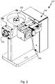
- FIG. 1 A hologram exposure machine 300 for exposing holograms in a hologram film 200 is shown schematically. Such a hologram exposure machine 300 is also referred to as a holosetter.
- the hologram exposure machine 300 comprises an exposure device 302 shown at the top in the drawing and an exposure table 100 shown at the bottom in the drawing.
- the exposure device 302 has a light source 304, which in the present case is designed as a cw laser.
- cw stands for “continuous wave” and means “wave emitted constant over time”.
- the light source 304 is a pulsed laser.
- a plurality of light sources 304 can also be present, each of which emits a different wavelength of the light.
- the light 400 of the light source 304 embodied as a laser has a first polarization state. Beam guiding optics 306 are used to guide the light 400.
- the light from the light source 304 is initially guided to a deflection and scanning device 310 of the optical beam guidance system 306 with the aid of a beam shaping device 322 for beam expansion, in particular oriented in one spatial direction.
- This deflection and scanning device 310 comprises a galvanometer scanner which can be driven in rotation and a mirror 308 which is coupled to the galvanometer scanner and on which the incident light 400 is deflected.
- the mirror 308 In a first position, the mirror 308 is shown by means of a solid line, while it is shown in a second position with dashed lines.
- an exposure of the hologram corresponding to a “scan”, in particular a line scan can take place.
- the hologram film 200 is "scanned" to expose the hologram.
- Deflection and scanning devices 310 of different types for the light 400 can also be used.
- the deflected light 400 is guided onto a polarization-dependent beam splitter cube 312 of the optical beam guiding system 306.
- This is formed from a first prism and a second prism, at their interface a polarization-dependent one Beam splitting takes place.
- a beam splitter plate can also be used instead of prisms.
- Light 400 of the first polarization state is deflected at this interface.
- light of a further polarization state orthogonal to the first polarization state can pass through the interface.
- the light 400 deflected at the interface of the polarization-dependent beam splitter cube 312 is directed onto a spatial light modulator 314, which is designed as a so-called liquid crystal-on-silicon light modulator (LCoS).
- the light modulator 314 comprises a silicon layer 316 on which incident light 400 is reflected.
- electronic switching elements are formed on this silicon layer 316, which are used to switch liquid crystal cells 318, which are arranged in front of the surface of the silicon layer 316 used for reflection.
- the individual liquid crystal cells 318 can be put individually into different switching states.
- An array of liquid crystal cells 318 is typically present, so that further rows of liquid crystal cells 318 are present, offset from or into the plane of the paper.
- a polarization state of the light 400 passing through is changed or not changed, as a result of which the light 400 is spatially modulated.
- the light 400 impinging on the light modulator 314 in a first polarization state is changed overall in terms of polarization when it passes through a liquid crystal cell 318, which is passed through twice due to the reflection on the surface of the silicon layer 316 that the light 400 is then polarized in the further polarization state orthogonal to the first polarization state.
- This polarization-modulated light 400 passes through a transparent protective pane 320 of the spatial light modulator 314, in particular an exit surface of the protective pane 320 being oriented parallel to the reflective surface of the silicon layer 316.
- the surface normal of the light modulator 314 is thus orthogonal both to the exit surface of the protective pane 320 and to the reflective surface of the silicon layer 316.
- the modulated light After exiting the light modulator 314, the modulated light strikes the polarization-dependent beam splitter 312 again, and the modulated light 400 reflected back by the LCoS may or may not pass the interface of the beam splitter 312 depending on its polarization state. If the modulated light 400, as in the example shown, has been converted into the further polarization state orthogonal to the first polarization state due to the first switching state of the liquid crystal cell, it can pass the interface of the polarization-dependent beam splitter cube 312, whereby it can, if necessary, with the aid of a polarization filter 324, is passed further in the direction of the exposure table 100.
- Portions of the light 400 that are still in the first polarization state and arrive at the polarization-dependent beam splitter cube 312 are deflected at its interface and therefore do not travel further in the direction of the exposure table 100 located below the exposure device 302 the light 400 is thus spatially modulated in terms of intensity as a function of the modulated polarization state.
- the spatial light modulator 314 rotates the polarization state of the light by 90 degrees or leaves it unchanged.
- changes are also possible which cause a rotation of the polarization direction between 0 degrees and 90 degrees. All these rotations lead to the light having a changed amplitude and thus a changed intensity of the further polarization state.
- these vary and increase with the amount of rotation between 0 degrees and 90 degrees. This makes it possible to expose "gray levels".
- the exposure table 100 has a holding device 102 in which a master 104 is received.
- the master 104 comprises a carrier, which is usually formed from glass or another material. Other carrier materials are also possible, for example metals.
- At least one optically active layer for example a diffraction layer, which comprises a diffraction structure to be copied, is preferably applied to the carrier.
- the Diffraction layer of the master 104 is a volume reflection hologram to be copied.
- the exposure machine 300 in particular the exposure table 100, comprises a film transport device 106 which is designed to transport the hologram film 200 relative to the holding device 102 and thus relative to the master 104.
- the film transport device 106 is provided for picking up the holographic film and holding and / or guiding the film during the exposure of the hologram.
- the film transport device 106 comprises a film roll 110 on which the hologram film 200 is provided. After exposure, this is wound onto a further roll of film 118.
- the exposed hologram film 200 runs through a route for developing the holograms, through which the hologram film 200 is thermally acted upon in order to fix the hologram in the film before the exposed hologram film 200 is wound up again on the further film roll 118.
- the hologram film 200 is typically guided by means of film guide rollers. It can be seen that the hologram film 200 extends over the area of the master 104, so that the film transport device 106, in other words, is designed to position a film section 202 to be exposed relative to the master 104. The volume reflection hologram is exposed, and therefore copied, into this film section 202.
- the hologram film 200 lies against the master 104 during the exposure process. This system can suppress the holographic film's own movements, which increases the achievable diffraction efficiency of the hologram produced.
- the modulated light 400 which has the further polarization state, passes through the film section 202 of the hologram film 200 to be exposed and is deflected back at the optically active structure of the at least one optically active layer of the master 104, e.g. in the case of an optically designed as a diffraction layer active layer bent.
- the reflected light (not shown) then interferes in the hologram film 200 with the modulated light 400 coming from the light modulator 314.
- the optically active structure for example the diffractive structure, of the master 104 is exposed into the hologram film 200.
- the optically active structure is either exposed and copied pixel by pixel depending on the spatial modulation or, on the other hand, not exposed and therefore not copied either.
- a copy of the optically active structure is thus created, for example a copy of a volume reflection hologram of a ground glass.
- the holding device 102 is assigned a compressed air device 108 which is designed to fix the film section 202 at least temporarily by means of a negative pressure on the master 104 accommodated in the holding device 102.
- a slot which is arranged circumferentially around the master 104 and thus forms a gas passage arrangement 112.
- the gas passage arrangement 112 thus frames the master 104 on the circumferential side and thus ensures that the film section 202 to be exposed is in contact with the master 104 without bubbles of the master 104 is carried out supported by an air cushion, which additionally prevents damage to the hologram film 200.
- a wiper device 120 is also present in order to wipe the film section 202 to be exposed onto the master 104.
- this wiper device 120 is formed by a slide which can be displaced between two stops and on which a pressure roller is mounted which is rotatably mounted on an axis of rotation and which interacts with the film section 202 when it is wiped on.
- the present invention is concerned with the beam shaping device 322 for expanding the light emitted by the light source 304.
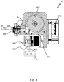
- a beam shaping device 322 is shown in FIG Figure 2 shown in more detail based on the section according to Figure 3 is explained in more detail.
- the beam shaping device 322 for the previously explained hologram exposure machine 300 comprises an entry opening 350 for the light 400 emitted by the light source 304 Cylindrical lens for focusing the incident light beam on a lateral surface 354 of a wheel 352 is formed.
- This wheel 352 has a base surface formed as a regular polygon (for example, polygon), a cover surface corresponding to the base surface and a jacket surface 354 which connects the base surface to the cover surface and is formed from mirrored rectangles.
- the wheel 352 is mounted rotatably about an axis of rotation, an electric drive unit 356 being present and designed to drive the wheel 352 in rotation about the axis of rotation oriented perpendicularly with respect to the direction of incidence of the light 400.
- an electric drive unit 356 being present and designed to drive the wheel 352 in rotation about the axis of rotation oriented perpendicularly with respect to the direction of incidence of the light 400.
- the light 400 reflected by the lateral surface 354 emerges from the beam shaping device 322 from an exit opening 358, into which a cylindrical lens 362 is introduced, which in the present case is designed as a plano-convex lens.
- a line 402 is produced by the cylinder lens 362, which is present quasistatically at a sufficient number of revolutions of the wheel 352.
- the drive unit 356 is designed in the present case to drive the wheel 352 with at least 1000 revolutions, in particular with 3000 to 5000 revolutions / min.
- the rectangles forming the lateral surface 354 have a width aligned perpendicularly with respect to the axis of rotation, which is smaller than the dimension of the cylindrical lens 362 aligned perpendicularly with respect to the axis of rotation the direction of incidence of the light 400 and the at least one direction of emergence of the reflected from the lateral surface 354
- Light 400 are aligned perpendicularly with respect to the axis of rotation of the wheel 352 and laterally offset to this.
- a line segment is caused by the beam-shaping device 322 by the rapid rotary movement of the wheel 352, which line segment has a quasi-homogeneous intensity distribution over its dimensions.
- the beam shaping device 322 formed in this way no longer has the disadvantages of using a Powell lens for beam expansion and is therefore particularly suitable for use in the hologram exposure machine 300.
- This hologram exposure machine 300 is characterized by a reliable exposure of holograms, so that the scrap rate, i.e. the number of defective holograms, is drastically reduced or reduced to a minimum.
Landscapes
- Physics & Mathematics (AREA)
- General Physics & Mathematics (AREA)
- Optics & Photonics (AREA)
- Holo Graphy (AREA)
Applications Claiming Priority (1)
| Application Number | Priority Date | Filing Date | Title |
|---|---|---|---|
| DE102020103616.7A DE102020103616B4 (de) | 2020-02-12 | 2020-02-12 | Hologrammbelichtungsmaschine und strahlformungseinrichtung für eine solche |
Publications (1)
| Publication Number | Publication Date |
|---|---|
| EP3865949A1 true EP3865949A1 (fr) | 2021-08-18 |
Family
ID=74561734
Family Applications (1)
| Application Number | Title | Priority Date | Filing Date |
|---|---|---|---|
| EP21155711.1A Pending EP3865949A1 (fr) | 2020-02-12 | 2021-02-08 | Machine d'exposition hologramme et dispositif de formation de faisceau pour une telle machine d'exposition hologramme |
Country Status (2)
| Country | Link |
|---|---|
| EP (1) | EP3865949A1 (fr) |
| DE (1) | DE102020103616B4 (fr) |
Citations (7)
| Publication number | Priority date | Publication date | Assignee | Title |
|---|---|---|---|---|
| EP0896260A2 (fr) | 1997-08-06 | 1999-02-10 | HSM Holographic Systems München GmbH | Dispositif pour la fabrication d'hologrammes individuels pour la sécurité de documents |
| DE102007042385A1 (de) | 2007-09-04 | 2009-03-05 | Bundesdruckerei Gmbh | Verfahren und Vorrichtung zur individuellen holografischen Trommelbelichtung |
| DE102007042386A1 (de) | 2007-09-04 | 2009-03-05 | Bundesdruckerei Gmbh | Verfahren und Vorrichtung zur individuellen farbigen holografischen Belichtung |
| CA2697850A1 (fr) * | 2007-09-10 | 2009-03-19 | Uab "Geola Digital" | Procede pour copie de contact d'hologrammes et impressions holographiques |
| US20110013250A1 (en) * | 2009-07-14 | 2011-01-20 | Konica Minolta Business Technologies, Inc. | Light deflection apparatus |
| DE102012215540A1 (de) | 2012-08-31 | 2014-03-06 | Bundesdruckerei Gmbh | Individualisierungseinrichtung und Belichtungsvorrichtung für Hologramme |
| KR20170115740A (ko) * | 2016-04-08 | 2017-10-18 | 인하대학교 산학협력단 | 폴리곤 미러를 이용한 광 주사장치 |
Family Cites Families (1)
| Publication number | Priority date | Publication date | Assignee | Title |
|---|---|---|---|---|
| DE102005054396A1 (de) | 2004-11-26 | 2006-06-01 | Giesecke & Devrient Gmbh | Markierung von Gegenständen mit Vielspiegelelementen |
-
2020
- 2020-02-12 DE DE102020103616.7A patent/DE102020103616B4/de active Active
-
2021
- 2021-02-08 EP EP21155711.1A patent/EP3865949A1/fr active Pending
Patent Citations (7)
| Publication number | Priority date | Publication date | Assignee | Title |
|---|---|---|---|---|
| EP0896260A2 (fr) | 1997-08-06 | 1999-02-10 | HSM Holographic Systems München GmbH | Dispositif pour la fabrication d'hologrammes individuels pour la sécurité de documents |
| DE102007042385A1 (de) | 2007-09-04 | 2009-03-05 | Bundesdruckerei Gmbh | Verfahren und Vorrichtung zur individuellen holografischen Trommelbelichtung |
| DE102007042386A1 (de) | 2007-09-04 | 2009-03-05 | Bundesdruckerei Gmbh | Verfahren und Vorrichtung zur individuellen farbigen holografischen Belichtung |
| CA2697850A1 (fr) * | 2007-09-10 | 2009-03-19 | Uab "Geola Digital" | Procede pour copie de contact d'hologrammes et impressions holographiques |
| US20110013250A1 (en) * | 2009-07-14 | 2011-01-20 | Konica Minolta Business Technologies, Inc. | Light deflection apparatus |
| DE102012215540A1 (de) | 2012-08-31 | 2014-03-06 | Bundesdruckerei Gmbh | Individualisierungseinrichtung und Belichtungsvorrichtung für Hologramme |
| KR20170115740A (ko) * | 2016-04-08 | 2017-10-18 | 인하대학교 산학협력단 | 폴리곤 미러를 이용한 광 주사장치 |
Also Published As
| Publication number | Publication date |
|---|---|
| DE102020103616A1 (de) | 2021-08-12 |
| DE102020103616B4 (de) | 2023-10-05 |
Similar Documents
| Publication | Publication Date | Title |
|---|---|---|
| EP2703907B1 (fr) | Dispositif d'individualisation et dispositif d'éclairage pour des hologrammes | |
| DE102014200633B3 (de) | Bearbeitungsvorrichtung und -verfahren zur Laserbearbeitung einer Oberfläche | |
| EP2203790B1 (fr) | Procédé et dispositif de pose holographique individuel à tambour | |
| DE102021101164A1 (de) | Verfahren und Vorrichtung zum Herstellen eines dreidimensionalen Objekts in einem optisch reaktiven Ausgangsmaterial | |
| EP2353050B1 (fr) | Procédé et dispositif de production d'hologrammes volumiques en transmission et en réflexion | |
| DE202015105046U1 (de) | Vorrichtung zum getrennten Modulieren der Wellenfronten von zwei Komponenten eines Lichtstrahls | |
| DE10196379B3 (de) | Mehrstrahl-Mustergenerator | |
| EP3657266B1 (fr) | Dispositif et procédé de génération d'un hologramme | |
| DE102020103616B4 (de) | Hologrammbelichtungsmaschine und strahlformungseinrichtung für eine solche | |
| DE3025131A1 (de) | Verfahren zum herstellen eines mit mono- oder polychromatischem licht rekonstruierbaren hologramms | |
| DE10122484A1 (de) | Verfahren und Vorrichtung zur Belichtung von Druckformen | |
| DE102020103617B4 (de) | Hologrammbelichtungsmaschine zum einbringen eines volumenreflexionshologramms in einen filmabschnitt eines hologrammfilms und verfahren zum einbringen mehrerer volumenreflexionshologramme in einen filmabschnitt eines hologrammfilms | |
| EP2895921B1 (fr) | Méthode de création d'un hologramme de réflexion volumique à formation de repères améliorée | |
| DE102020103618B4 (de) | Hologrammbelichtungsmaschine und verfahren zum justieren einer hologrammbelichtungsmaschine | |
| DE102020103612B4 (de) | Belichtungstisch für eine hologrammbelichtungsmaschine und verfahren zum einbringen eines volumenhologramms in einen filmabschnitt | |
| EP3865950A1 (fr) | Machine d'exposition hologramme permettant d'introduire un hologramme de réflexion de volume dans un film hologramme | |
| EP3865948A1 (fr) | Table d'exposition pour une machine d'exposition hologramme et procédé d'insertion d'un hologramme de réflexion de volume dans une section de film | |
| EP1385057A2 (fr) | Appareil compact pour l'exposition d'un élément d'impression | |
| EP3869275B1 (fr) | Table d'exposition pour une machine d'exposition hologramme | |
| DE19802712B4 (de) | Verfahren und Vorrichtung zur Belichtung von computergenerierten Hologrammen | |
| EP3792699B1 (fr) | Dispositif et procédé de détection d'une caractéristique holographique | |
| DE4404118C2 (de) | Vorrichtung zur Veränderung der Richtung der Strahlung eines Lasers | |
| DE112022003132T5 (de) | Laserbearbeitungsvorrichtung und Laserbearbeitungsverfahren | |
| DE2814279A1 (de) | Vorrichtung zur auswahl eines aus mehreren optischen zeichengeneratoren | |
| EP2539152A1 (fr) | Dispositif de marquage et procédé de marquage de documents de valeur ou de sécurité, à l'aide de fibres optiques |
Legal Events
| Date | Code | Title | Description |
|---|---|---|---|
| PUAI | Public reference made under article 153(3) epc to a published international application that has entered the european phase |
Free format text: ORIGINAL CODE: 0009012 |
|
| STAA | Information on the status of an ep patent application or granted ep patent |
Free format text: STATUS: THE APPLICATION HAS BEEN PUBLISHED |
|
| AK | Designated contracting states |
Kind code of ref document: A1 Designated state(s): AL AT BE BG CH CY CZ DE DK EE ES FI FR GB GR HR HU IE IS IT LI LT LU LV MC MK MT NL NO PL PT RO RS SE SI SK SM TR |
|
| STAA | Information on the status of an ep patent application or granted ep patent |
Free format text: STATUS: REQUEST FOR EXAMINATION WAS MADE |
|
| 17P | Request for examination filed |
Effective date: 20220217 |
|
| RBV | Designated contracting states (corrected) |
Designated state(s): AL AT BE BG CH CY CZ DE DK EE ES FI FR GB GR HR HU IE IS IT LI LT LU LV MC MK MT NL NO PL PT RO RS SE SI SK SM TR |
|
| P01 | Opt-out of the competence of the unified patent court (upc) registered |
Effective date: 20230526 |