EP3865437A1 - Method for moving a product stack with a robot - Google Patents
Method for moving a product stack with a robot Download PDFInfo
- Publication number
- EP3865437A1 EP3865437A1 EP21152258.6A EP21152258A EP3865437A1 EP 3865437 A1 EP3865437 A1 EP 3865437A1 EP 21152258 A EP21152258 A EP 21152258A EP 3865437 A1 EP3865437 A1 EP 3865437A1
- Authority
- EP
- European Patent Office
- Prior art keywords
- product stack
- product
- robot
- stack
- gripper
- Prior art date
- Legal status (The legal status is an assumption and is not a legal conclusion. Google has not performed a legal analysis and makes no representation as to the accuracy of the status listed.)
- Pending
Links
- 238000000034 method Methods 0.000 title claims abstract description 38
- 238000000151 deposition Methods 0.000 claims description 36
- 238000007665 sagging Methods 0.000 claims description 7
- 238000011161 development Methods 0.000 description 85
- 230000018109 developmental process Effects 0.000 description 85
- 238000012545 processing Methods 0.000 description 15
- 230000009471 action Effects 0.000 description 5
- 238000012546 transfer Methods 0.000 description 5
- 210000000080 chela (arthropods) Anatomy 0.000 description 4
- 230000008021 deposition Effects 0.000 description 4
- 238000012549 training Methods 0.000 description 4
- 239000011111 cardboard Substances 0.000 description 3
- 230000008859 change Effects 0.000 description 3
- 238000004519 manufacturing process Methods 0.000 description 3
- 238000000926 separation method Methods 0.000 description 3
- 239000011230 binding agent Substances 0.000 description 2
- 239000002184 metal Substances 0.000 description 2
- 239000000123 paper Substances 0.000 description 2
- 238000009423 ventilation Methods 0.000 description 2
- 238000013022 venting Methods 0.000 description 2
- 230000002745 absorbent Effects 0.000 description 1
- 239000002250 absorbent Substances 0.000 description 1
- 239000000853 adhesive Substances 0.000 description 1
- 230000001070 adhesive effect Effects 0.000 description 1
- 230000004888 barrier function Effects 0.000 description 1
- 230000008901 benefit Effects 0.000 description 1
- 238000007664 blowing Methods 0.000 description 1
- 239000002131 composite material Substances 0.000 description 1
- 230000001419 dependent effect Effects 0.000 description 1
- 230000000694 effects Effects 0.000 description 1
- 230000006872 improvement Effects 0.000 description 1
- 238000005259 measurement Methods 0.000 description 1
- 239000007769 metal material Substances 0.000 description 1
- 238000012544 monitoring process Methods 0.000 description 1
- 238000004091 panning Methods 0.000 description 1
- 239000004033 plastic Substances 0.000 description 1
- 230000008569 process Effects 0.000 description 1
Images


Classifications
-
- B—PERFORMING OPERATIONS; TRANSPORTING
- B65—CONVEYING; PACKING; STORING; HANDLING THIN OR FILAMENTARY MATERIAL
- B65G—TRANSPORT OR STORAGE DEVICES, e.g. CONVEYORS FOR LOADING OR TIPPING, SHOP CONVEYOR SYSTEMS OR PNEUMATIC TUBE CONVEYORS
- B65G47/00—Article or material-handling devices associated with conveyors; Methods employing such devices
- B65G47/74—Feeding, transfer, or discharging devices of particular kinds or types
- B65G47/90—Devices for picking-up and depositing articles or materials
- B65G47/905—Control arrangements
-
- B—PERFORMING OPERATIONS; TRANSPORTING
- B65—CONVEYING; PACKING; STORING; HANDLING THIN OR FILAMENTARY MATERIAL
- B65H—HANDLING THIN OR FILAMENTARY MATERIAL, e.g. SHEETS, WEBS, CABLES
- B65H31/00—Pile receivers
- B65H31/30—Arrangements for removing completed piles
- B65H31/3036—Arrangements for removing completed piles by gripping the pile
- B65H31/3045—Arrangements for removing completed piles by gripping the pile on the outermost articles of the pile for clamping the pile
-
- B—PERFORMING OPERATIONS; TRANSPORTING
- B25—HAND TOOLS; PORTABLE POWER-DRIVEN TOOLS; MANIPULATORS
- B25J—MANIPULATORS; CHAMBERS PROVIDED WITH MANIPULATION DEVICES
- B25J9/00—Programme-controlled manipulators
- B25J9/16—Programme controls
-
- B—PERFORMING OPERATIONS; TRANSPORTING
- B25—HAND TOOLS; PORTABLE POWER-DRIVEN TOOLS; MANIPULATORS
- B25J—MANIPULATORS; CHAMBERS PROVIDED WITH MANIPULATION DEVICES
- B25J15/00—Gripping heads and other end effectors
- B25J15/0052—Gripping heads and other end effectors multiple gripper units or multiple end effectors
- B25J15/0061—Gripping heads and other end effectors multiple gripper units or multiple end effectors mounted on a modular gripping structure
-
- B—PERFORMING OPERATIONS; TRANSPORTING
- B25—HAND TOOLS; PORTABLE POWER-DRIVEN TOOLS; MANIPULATORS
- B25J—MANIPULATORS; CHAMBERS PROVIDED WITH MANIPULATION DEVICES
- B25J15/00—Gripping heads and other end effectors
- B25J15/02—Gripping heads and other end effectors servo-actuated
- B25J15/0253—Gripping heads and other end effectors servo-actuated comprising parallel grippers
-
- B—PERFORMING OPERATIONS; TRANSPORTING
- B25—HAND TOOLS; PORTABLE POWER-DRIVEN TOOLS; MANIPULATORS
- B25J—MANIPULATORS; CHAMBERS PROVIDED WITH MANIPULATION DEVICES
- B25J9/00—Programme-controlled manipulators
- B25J9/16—Programme controls
- B25J9/1679—Programme controls characterised by the tasks executed
- B25J9/1687—Assembly, peg and hole, palletising, straight line, weaving pattern movement
-
- B—PERFORMING OPERATIONS; TRANSPORTING
- B65—CONVEYING; PACKING; STORING; HANDLING THIN OR FILAMENTARY MATERIAL
- B65G—TRANSPORT OR STORAGE DEVICES, e.g. CONVEYORS FOR LOADING OR TIPPING, SHOP CONVEYOR SYSTEMS OR PNEUMATIC TUBE CONVEYORS
- B65G47/00—Article or material-handling devices associated with conveyors; Methods employing such devices
- B65G47/22—Devices influencing the relative position or the attitude of articles during transit by conveyors
- B65G47/24—Devices influencing the relative position or the attitude of articles during transit by conveyors orientating the articles
- B65G47/248—Devices influencing the relative position or the attitude of articles during transit by conveyors orientating the articles by turning over or inverting them
-
- B—PERFORMING OPERATIONS; TRANSPORTING
- B65—CONVEYING; PACKING; STORING; HANDLING THIN OR FILAMENTARY MATERIAL
- B65G—TRANSPORT OR STORAGE DEVICES, e.g. CONVEYORS FOR LOADING OR TIPPING, SHOP CONVEYOR SYSTEMS OR PNEUMATIC TUBE CONVEYORS
- B65G47/00—Article or material-handling devices associated with conveyors; Methods employing such devices
- B65G47/74—Feeding, transfer, or discharging devices of particular kinds or types
- B65G47/90—Devices for picking-up and depositing articles or materials
-
- B—PERFORMING OPERATIONS; TRANSPORTING
- B65—CONVEYING; PACKING; STORING; HANDLING THIN OR FILAMENTARY MATERIAL
- B65G—TRANSPORT OR STORAGE DEVICES, e.g. CONVEYORS FOR LOADING OR TIPPING, SHOP CONVEYOR SYSTEMS OR PNEUMATIC TUBE CONVEYORS
- B65G61/00—Use of pick-up or transfer devices or of manipulators for stacking or de-stacking articles not otherwise provided for
-
- B—PERFORMING OPERATIONS; TRANSPORTING
- B65—CONVEYING; PACKING; STORING; HANDLING THIN OR FILAMENTARY MATERIAL
- B65H—HANDLING THIN OR FILAMENTARY MATERIAL, e.g. SHEETS, WEBS, CABLES
- B65H31/00—Pile receivers
- B65H31/34—Apparatus for squaring-up piled articles
-
- B—PERFORMING OPERATIONS; TRANSPORTING
- B65—CONVEYING; PACKING; STORING; HANDLING THIN OR FILAMENTARY MATERIAL
- B65H—HANDLING THIN OR FILAMENTARY MATERIAL, e.g. SHEETS, WEBS, CABLES
- B65H2301/00—Handling processes for sheets or webs
- B65H2301/30—Orientation, displacement, position of the handled material
- B65H2301/33—Modifying, selecting, changing orientation
- B65H2301/333—Inverting
-
- B—PERFORMING OPERATIONS; TRANSPORTING
- B65—CONVEYING; PACKING; STORING; HANDLING THIN OR FILAMENTARY MATERIAL
- B65H—HANDLING THIN OR FILAMENTARY MATERIAL, e.g. SHEETS, WEBS, CABLES
- B65H2407/00—Means not provided for in groups B65H2220/00 – B65H2406/00 specially adapted for particular purposes
- B65H2407/10—Safety means, e.g. for preventing injuries or illegal operations
-
- B—PERFORMING OPERATIONS; TRANSPORTING
- B65—CONVEYING; PACKING; STORING; HANDLING THIN OR FILAMENTARY MATERIAL
- B65H—HANDLING THIN OR FILAMENTARY MATERIAL, e.g. SHEETS, WEBS, CABLES
- B65H2701/00—Handled material; Storage means
- B65H2701/10—Handled articles or webs
- B65H2701/13—Parts concerned of the handled material
- B65H2701/132—Side portions
- B65H2701/1322—Side portions corner
-
- B—PERFORMING OPERATIONS; TRANSPORTING
- B65—CONVEYING; PACKING; STORING; HANDLING THIN OR FILAMENTARY MATERIAL
- B65H—HANDLING THIN OR FILAMENTARY MATERIAL, e.g. SHEETS, WEBS, CABLES
- B65H2701/00—Handled material; Storage means
- B65H2701/10—Handled articles or webs
- B65H2701/19—Specific article or web
- B65H2701/1932—Signatures, folded printed matter, newspapers or parts thereof and books
Definitions
- the invention relates to a method having the features of the preamble of claim 1.
- the invention is in the technical field of the graphic industry and there in particular in the field of handling (e.g. gripping, holding, moving, rotating, turning and / or depositing) of product stacks of preferably printed and folded flat products, preferably made of paper, cardboard, cardboard , Plastic, metal or composite material, with a manipulator, in particular a robot or an articulated arm robot.
- a manipulator in particular a robot or an articulated arm robot.
- the JPS6048848A discloses in FIG. 11d the grasping at diagonally opposite corners of a product stack and in FIG. 9 the sagging of the product stack.
- the two grippers shown belong to two separate robots.
- the EP1645434B1 discloses the pivoting of a product stack into a standing position and the transfer of the product stack to a clamp or the gripping of the product stack from above.
- the EP2128056A1 discloses a robot with an articulated arm for handling a stack and in Figure 4 a gripping device.
- the DE202019106975U1 discloses a handling device for transferring a stack of products, the handling device comprising a gripping device which is movable in three dimensions.
- the gripping device comprises a first and a second lateral delimitation element as well as an upper and lower holding element which is mounted linearly displaceably along each delimitation element.
- the invention relates to a method for moving a product stack with a robot, the robot comprising an articulated arm and, arranged on the articulated arm, at least one gripper for the product stack and wherein the product stack is optionally turned.
- the invention is characterized in that moving on a selected placement position of several placement positions of a specified placement scheme ends.
- the invention makes it possible in an advantageous manner to move product stacks in an automated manner and, in particular, to turn them over or to put them down.
- the product stack is moved to a selected depositing position from a plurality of depositing positions of a predetermined depositing scheme and is preferably deposited there.
- the withdrawal scheme can be stored in a digital computer or a network connected to it.
- a plurality of dispatching schemes can be stored, e.g. in a database.
- the selection of the depositing position (and / or a sequence of depositing positions for product stacks to be moved one after the other) can be computer-controlled.
- a depositing scheme can be selected for each horizontal position; in particular, different depositing schemes can be selected for two successive layers.
- the term “optional” means that the product stack is either turned or is not turned.
- the selection can preferably be made by a digital computer and can be made by the digital computer in particular as a function of a so-called offset pattern.
- the term “optional” is also intended to make it clear that the method can be carried out several times in succession with one product stack each and that at least one product stack is turned over and at least one product stack is not turned over.
- a further development can be characterized in that the product stack is set down on a base, preferably a pallet, at the selected set-down position.
- a further development can be characterized in that the product stack is held in such a way that the product stack sags diagonally and that when the diagonally sagging product stack is set down, the sag initially touches the base.
- a further development can be characterized in that the withdrawal scheme is stored in a digital computer or is loaded onto the digital computer from another digital computer via a network and that the movement is controlled by the digital computer.
- a further development can be characterized in that the depositing scheme is calculated and / or selected by the digital computer as a function of at least one of the following parameters: dimensions of the product stack; Dimensions of the base; Product stacks formed in the case of folded products: Position of the folded edges relative to the base and / or structure of the folded edges depending on the type of fold.
- a further development can be characterized in that several product stacks are moved one after the other, optionally turned, optionally rotated horizontally and deposited at selected depositing positions from several depositing positions of the specified depositing scheme.
- a computer-controlled robot with an articulated arm and a gripping device can be used.
- the product stack is advantageously pivoted in two steps and optionally turned over.
- In the first step there is a pivoting through an effective angle ⁇ 1 ⁇ > 180 °.
- ⁇ 1 and ⁇ 2 are both 90 °, then a turn is made by 180 °.
- ⁇ 1 and ⁇ 2 are e.g. 90 ° and -90 °, no turning takes place.
- the 2-step swivel method makes it possible to insert intermediate steps, e.g. jogging and / or jogging the product stack. Furthermore, the 2-step swivel method advantageously enables the two steps to be carried out at different positions, e.g. by the robot executing a movement in between. Furthermore, the 2-step swivel method advantageously enables the two steps to be carried out using different devices, e.g. using the robot and using a swivel device different from the robot.
- an effective angle of + 90 ° can therefore be achieved, for example, by swiveling by + 90 °, by swiveling twice by + 45 ° each or by swiveling by -270 °.
- angle can also simply be used.
- a further development can be characterized in that the pivoting through the effective angle ⁇ 1 takes place with a pivoting device different from the robot.
- the pivoting device can be assigned to a boom of a further processing machine, in particular a folding machine, and in particular be arranged on this. It can comprise a pivotable gripper for the product stack.
- the swivel device can be controlled by a digital computer.
- a further development can be characterized in that the pivoting by the effective angle ⁇ 1 takes place before the movement or the movement starts from the pivoted position of the product stack out.
- the movement is preferably done with the robot arm.
- a further development can be characterized in that the pivoting takes place by the effective angle ⁇ 1 about a horizontal axis.
- the axis can be aligned parallel to the transport direction of a boom of a further processing machine, in particular a folding machine.
- the product stack is preferably gripped and held.
- a further development can be characterized in that the product stack is pivoted out of a horizontal position when pivoting through the effective angle ⁇ 1.
- the individual products of the product stack e.g. folded signatures, preferably lie horizontally.
- a further development can be characterized in that the product stack is pivoted into a vertical position when pivoting through the effective angle ⁇ 1.
- the individual products of the product stack preferably "stand" in the vertical position.
- a further development can be characterized in that the product stack is aligned outside of the horizontal position and / or pushed straight in one direction and / or pushed and / or jogged and / or ventilated in two mutually perpendicular directions and / or that a fanned-out product stack is not in one direction fanned out product stack is changed ("fan out").
- the product stack can be in the swivel device, for example in its gripper.
- the gripper can be slightly open, especially for ventilation.
- a device for straightening and / or fan-out can comprise two mutually movable, perpendicular surfaces, for example metal sheets, preferably with lateral bevels. This device can be opened before pivoting and closed after pivoting. For this purpose, the surfaces can be moved away from one another and towards one another. Pneumatic cylinders can be provided for shaking.
- the device or its surfaces preferably move into an open position so that the product stack can be taken over.
- a further development can be characterized in that the product stack is rotated in the vertical position about a vertical axis, preferably by 180 °. This makes it possible in an advantageous manner to grasp the product stack in the vertical position, both when optionally turning it over and when optionally not turning it over, from the same side. Rotation can be done with the swivel device.
- This can include a rotary drive for this purpose.
- the rotary drive can be controlled by a digital computer.
- a further development can be characterized in that the product stack is taken over from one side of the product stack when it is turned and that the product stack is taken over from the same side of the product stack when it is not turned.
- the transfer from one side or the other can be carried out with an articulated arm of the robot.
- the side can be selected under computer control.
- a specified withdrawal scheme can be taken into account.
- a further development can be characterized in that the robot takes over the product stack in the vertical position.
- the robot and in particular its gripper can be moved towards the product stack under computer control, e.g. from above and / or from one side.
- a further development can be characterized in that the product stack is moved in the vertical position, at least over part of the movement.
- the position of the product stack can be changed along the path of the movement, e.g. by pivoting (about a horizontal axis) and / or rotating (about a vertical axis).
- a further development can be characterized in that the robot takes over the product stack from the pivoting device and then moves it.
- the product stack can be taken over and held using a gripping device of the robot.
- the movement can take place by moving an articulated arm of the robot.
- the robot can also be moved horizontally. All actions of the robot can preferably be computer-controlled.
- a further development can be characterized in that the product stack is taken over from one side of the product stack when it is turned and that the product stack is taken over from the opposite side of the product stack when it is not turned.
- the transfer from one side or the other can be carried out with an articulated arm of the robot.
- a gripping device of the robot can be rotated in such a way that gripping takes place from one side or from the other side.
- the side can be selected under computer control.
- a specified withdrawal scheme can be taken into account.
- a further development can be characterized in that the pivoting by the effective angle ⁇ 2 takes place during the movement or between two partial movements or after the movement.
- the pivoting can be computer-controlled.
- a specified withdrawal scheme can be taken into account.
- a further development can be characterized in that the pivoting takes place through the effective angle a2 with the robot.
- the pivoting can take place by moving an articulated arm of the robot accordingly and / or can take place by a pivoting device on the robot or on its articulated arm and / or by a pivotable gripping device on the robot or on its articulated arm.
- the pivoting can be computer-controlled.
- a further development can be characterized in that the product stack is pivoted back into a horizontal position when pivoting through the effective angle ⁇ 2. In this case, the product stack is not turned over, i.e. it is deposited without being turned over.
- a further development can be characterized in that the product stack is deposited in the horizontal position. They are preferably placed on a pallet. To put them down, grippers on the robot can be opened simultaneously or one after the other and moved away to the side.
- a further development can be characterized in that the product stack is rotated about a vertical axis before being deposited. This allows the horizontal alignment of the product stack to be changed, e.g. by effectively 90 ° or 180 °.
- the turning can be computer-controlled. A specified withdrawal scheme can be taken into account.
- the pivoting about ⁇ 1 and the pivoting about a2 preferably take place in the same pivoting direction.
- the product stack is turned "in total”.
- the pivoting about ⁇ 1 and the pivoting about ⁇ 2 preferably take place in opposite pivoting directions.
- the product stack is not turned "in total”.
- a further development can be characterized in that the product stack is held by at least two grippers while it is being moved.
- a further development can be characterized in that the product stack is held in a form-fitting and / or force-fitting manner while it is moving.
- a further development can be characterized in that one side of the product stack has at least four corners and that the product stack is held at diagonally opposite corners during the movement. If there are more than four corners, for example, those corners can be selected that have a large distance from one another and / or are diagonally opposite one another to a good approximation.
- a further development can be characterized in that either two diagonally opposite corners or two other diagonally opposite corners are held.
- the corners can be selected under computer control. It can be a prescribed withdrawal scheme must be taken into account.
- a gripping device on the robot arm is preferably rotated.
- a further development can be characterized in that the product stack is held in such a way that the product stack sags.
- the distance between the grippers of the robot can be reduced, preferably by computer control, up to a desired or predetermined sag.
- the product stack can be formed from folded sheets of paper.
- a further development can be characterized in that the product stack is held in such a way that the product stack sags diagonally. In this way, the product stack can be checked with the diagonal as the "lowest point" and set down in a self-locking manner. For this purpose, the product stack can be held at diagonally opposite corners.
- a further development can be characterized in that two grippers are used and that when the product stack is laid down or set down, the grippers are removed horizontally from the product stack in two directions perpendicular to one another.
- a further development can be distinguished by the fact that the grippers open vertically when the product stack is deposited or set down.
- a gripper jaw of the gripper can be moved, preferably a gripper jaw located above the product stack can be moved upwards.
- the other gripper jaw preferably the one below the product stack, can be immobile.
- a further development can be characterized in that each product stack is moved to a respectively selected depositing position of the depositing scheme that in the Set-down position, the grippers can be removed from the product stack horizontally without collision to product stacks that have already been set down.
- a further development can be characterized in that the product stack is moved from a display of a further processing machine for printed products to a pallet or to one of several pallets. In the latter case, non-stop operation is possible.
- a further development can be characterized in that the product stack is moved from a display of a further processing machine for printed products, e.g. a folding machine, a saddle stitcher or an adhesive binder, to a pallet or to one of several pallets.
- a further processing machine for printed products e.g. a folding machine, a saddle stitcher or an adhesive binder
- a further development can be characterized in that the product stacks in the display are transported in one transport direction and are separated from one another in the transport direction.
- the transport can take place on a roller conveyor. For the separation, individual drivable rollers can be driven or stopped accordingly.
- a further development can be characterized in that the robot is displaceable and can be used in several positions of a single further processing machine or on several further processing machines.
- the robot can be mounted on rollers and / or rails.
- a further development can be characterized in that the product stack is formed from folded and / or punched printed products.
- a further development can be characterized in that several product stacks - horizontally offset to one another - and in several horizontal planes one above the other to form a transport stack on a transport pallet are stacked or that a transport stack is formed or built up accordingly.
- the selection of the offset and / or the planes can be computer-controlled.
- a specified withdrawal scheme can be taken into account.
- a further development can be characterized in that a sensor arranged on the robot detects the height of the transport stack.
- the sensor can be arranged on a gripping device of the robot.
- Several sensors can be arranged.
- the height can be determined absolutely, e.g. measured from the upper edge of a pallet or the floor, or it can be determined relative to the distance to the sensor.
- a further development can be characterized in that a single height value, a set of height values at different horizontal positions or a height profile is recorded as the height.
- a further development can be characterized in that a distance sensor for measuring the height or a camera with digital image processing for calculating the height from the camera image is used as the sensor.
- a further development can be characterized in that the robot arm is moved without collision over an only partially built-up transport stack, the digital computer taking the detected height into account when controlling the movement of the robot arm.
- a further development can be characterized in that the robot removes individual intermediate layers from a stack and places them on the respective levels.
- the intermediate layers can be made of cardboard.
- the depositing of intermediate layers can be computer-controlled. A predefined depositing scheme and / or stacking scheme can be taken into account.
- a further development can be characterized in that the intermediate layer is held in an absorbent manner.
- a suction gripper can be arranged on a gripping device of the robot. Several such suction pads can be used.
- a further development can be characterized in that the movement takes place fully automatically, depending on a selected depositing scheme and / or stacking scheme and in coordination with the production speed of at least the further processing machine.
- a further development can be characterized in that the robot arm is moved within a protected zone.
- a further development can be characterized in that a housing and / or a fence and / or a light barrier and / or camera monitoring is used to establish the protected zone.
- a further development of the method according to the invention can be characterized in that a device is used for moving a product stack with a robot, the robot comprising an articulated arm on which a first gripper for the product stack is arranged.
- the method is characterized in that a gripping device is arranged on the articulated arm which comprises the first gripper and a second gripper, the first gripper and the second gripper being positioned relative to one another.
- the device mentioned can, as such, represent a further invention: A device for moving a product stack with a robot, the robot comprising an articulated arm on which a first gripper for the product stack is arranged.
- the device is characterized in that a gripping device is arranged on the articulated arm which comprises the first gripper and a second gripper, the first gripper and the second gripper being positionable relative to one another.
- the device as such or its use makes it possible in an advantageous manner to move product stacks in an automated manner and, in particular, to turn them over or to put them down.
- a further development can be characterized in that the two grippers can be positioned on predetermined formats of products or product stacks, preferably computer-controlled.
- the grippers can be movable, preferably linearly movable, for positioning. The positioning is preferably computer-controlled.
- a further development can be characterized in that the two grippers can be positioned on the two ends of a selected diagonal of a selected format.
- the positioning is preferably computer-controlled.
- a further development can be characterized in that the first gripper is designed as a first pincer gripper with a first pair of gripper jaws and that the second gripper is designed as a second pincer gripper with a second pair of gripper jaws.
- both pairs of gripper jaws each comprise an immovable gripper jaw and in each case a gripper jaw that is linearly movable relative to the immovable gripper jaw.
- Linear drives can be provided, preferably electrical ones with a threaded spindle.
- the immovable gripper jaws are of course not completely immobile: they can be moved by the movement of the robot, the gripping device and / or the gripper.
- the immovable gripper jaws are only immobile when the grippers are opened and closed or are only moved insignificantly in relation to the movable gripper jaws.
- the immovable gripper jaws each comprise a horizontally extending support element and in each case at least one vertically extending stop element.
- both immovable gripper jaws each comprise a horizontally extending support surface as a support element and two vertically extending and mutually perpendicular stop surfaces as stop elements. All surfaces can be perpendicular to each other.
- a further development can be characterized in that the product stack is held by the gripper jaws in a force-fitting and / or form-fitting manner.
- a further development can be characterized in that at least one blowing device is arranged on the gripping device, which blows air under the product stack when the product stack is deposited.
- a further development can be characterized in that at least one further gripper, which is designed as a suction gripper for intermediate layers, is arranged on the gripping device.
- the suction gripper can be supplied with suction air in a computer-controlled manner for gripping and holding by suction.
- a further development can be characterized in that at least one distance sensor and / or at least one camera is arranged on the gripping device.
- a further development can be characterized in that the gripping device comprises a first support arm, on which the first gripper is arranged to be linearly movable in the longitudinal direction of the first support arm.
- a further development can be characterized in that the gripping device comprises a second support arm, on which the second gripper is arranged so as to be linearly movable in the longitudinal direction of the second support arm.
- a linear drive can be provided on the support arm, preferably an electric one with a threaded spindle.
- the linear drive can be electric.
- the support arm can have a length which correlates with a maximum format product stack to be moved.
- a further development can be characterized in that the first support arm and the second support arm are arranged perpendicular to one another on the gripping device.
- the support arms can form an X-Y axis system for size adjustable grippers.
- Movable gripper jaws of the grippers can form the perpendicular Z-axis.
- a further development can be characterized in that the two linearly movable gripper jaws can be moved perpendicular to the respective support arm.
- a further development can be characterized in that the gripping device is arranged on the robot arm so that it can rotate about an axis of rotation.
- the axis of rotation is preferably used to rotate the product stack about a vertical axis and / or to set down a product stack that has been rotated horizontally.
- a further development can be characterized in that the gripping device is arranged on the robot arm so as to be pivotable about a pivot axis perpendicular to the axis of rotation.
- the pivot axis is preferably used to pivot the product stack about a horizontal axis and / or to set down a product stack that is either turned or not turned with respect to the horizontal.
- a further development can be characterized in that the articulated arm comprises six axes, preferably axes of rotation.
- a further development can be characterized in that the robot can be moved horizontally relative to one or more further processing machines or machines that generate product stacks, e.g. on rails or on rollers.
- the task can be achieved with a pivoting method in just one step.
- the product stack is preferably gripped from below for the optional turning in a horizontal orientation with the gripping device of an articulated arm robot and pivoted through an effective angle of 180 °, e.g. while it is moving towards the pallet. If, alternatively, it should not be turned, the product stack can be gripped in a horizontal orientation, preferably from above.
- FIGS. 1 to 8 show preferred exemplary embodiments of the invention and the developments. Features that correspond to one another are provided with the same reference symbols in the figures. Reference symbols that are repeated in the figures have partly been omitted for the sake of clarity.
- Figure 1 shows a preferred embodiment of a device, preferably comprising a robot, when performing steps of a preferred embodiment of the method according to the invention. A view from above is shown.
- a further processing machine 70 which is only partially shown, at a position 74, preferably a folding machine, produces printed products 2, preferably printed and / or folded signatures 2, which are moved e.g. conveyed in the form of product stacks 1 on a display 72 in a transport direction 71.
- the action of the delivery, in particular the conveyance, can be controlled by the digital computer 80.
- a product stack preferably comprises a multiplicity of products lying one on top of the other.
- a digital computer 80 which is preferably connected to a network 81, can control the further processing machine 70 and optionally other machines, e.g. provide order data for product manufacture. Order data can be made available via the network.
- the delivery 72 can move the product stacks 1 into a protected zone 73.
- a robot 10 can be arranged within this zone, which preferably comprises an articulated arm 11 with several axes 12, e.g. six axes.
- the robot can be a common industrial robot.
- a gripping device 20 is arranged on the robot 10, preferably at the end of its articulated arm 11 or “hand”.
- the gripping device can grasp and hold product stacks 1 and move them away from display 72 in space, preferably exclusively within the protected zone.
- the movement 15 moves the product stack 1 along a space curve to a transport pallet 62.
- the product stack is deposited there and is preferably deposited at a depositing position 60 in accordance with a depositing pattern 61.
- a plurality of pallets that can be reached by the robot can preferably be provided.
- the movement can comprise several partial movements 16.
- the gripping device can, for example, be rotated and / or pivoted between two partial movements. Rotating and / or pivoting can also take place while moving.
- a pivoting device 40 is preferably arranged at the end of the display 72. This can pivot the product stack 1 out of the horizontal 50 or a horizontal plane 53 or the horizontal position 52 into the vertical 54 or vertical plane 57 or the vertical position 56.
- the pivoting device can comprise two preferably horizontally movable alignment elements 41 and / or straight pusher 42 for the product stack. These can be designed as surfaces, e.g. sheets.
- the action, in particular the movement 15 and / or 16, of the robot 10 and / or the action, in particular the pivoting, of the pivoting device can be controlled by the digital computer 80.
- Figure 2 shows a preferred embodiment of a delivery of a further processing machine.
- the display 72 may include a plurality of rollers 76.
- the delivery can be a roller conveyor. Some of the rollers can be driven, for example by motors 75.
- the digital computer 80 can control the conveyance of the product stacks 1 of products 2 lying one on top of the other.
- the product stacks can be separated from one another in the transport direction 71.
- the products 2 and thus also the product stacks 1 formed preferably have four corners 5. Die-cut products can also have more corners. If the products are folded, their fold spines are preferably parallel to the direction of transport.
- Figures 3A and 3B show preferred exemplary embodiments of the delivery, preferably comprising a pivoting device, when performing steps of a preferred embodiment of the method according to the invention. A perspective view is shown in each case.
- Figures 3A and 3B show the end of the folding machine 70 and the delivery 72 on which the product stacks 1 are conveyed up to a pivoting device 40 in the transport direction 71 (method step transporting 101).
- the product stacks and thus the products 2 are preferably in a horizontal position 52 before being pivoted.
- the pivoting device 40 preferably comprises grippers 43, for example rods that can move relative to one another, preferably one rod (closing “hold-down”) on one side of the product stack 1 and three rods on the other side thereof.
- the pivoting device and / or its gripper can be pivoted about a horizontal axis 51.
- the grippers, which are located in Figure 3A located under the product stack 1 can be positioned between the rollers 76 and pivoted out of this position.
- Figures 3A and 3B show a detail of the robot 10 and its articulated arm 11.
- the robot can preferably be moved on the floor in the horizontal direction and can thus be positioned at different points.
- the robot can, for example, be mounted on rollers.
- rails can be provided.
- Figures 3A and 3B show the alignment elements 41 and / or straight pusher 42, which are preferably horizontally movable.
- the pivoting movement or pivoting 110 through an effective angle ⁇ 1 becomes clear (method step pivoting 110).
- the angle ⁇ 1 is preferably 90 °.
- the product stack 1 is preferably in a vertical position 56.
- the fold spines are preferably at the top in the vertical position.
- Figures 3A and 3B show two sides 3 and 4.
- the robot 1 can grasp the pivoted product stack 1 preferably from side 3 or the opposite side 4.
- Side 3 can be referred to as the front and side 4 as the back.
- the choice of the side can be done computer-controlled depending on a withdrawal scheme.
- the pivoting device can optionally be designed to be rotatable and thus rotated about a vertical axis 55.
- the product stack can preferably be rotated by 180 °. With this option, the robot 1 can always grasp the pivoted product stack 1 from the same side, preferably from side 3 or the front.
- Figures 4A to 4D show preferred exemplary embodiments of a robot-guided gripping device when performing steps of a preferred embodiment of the method according to the invention. A perspective view is shown in each case.
- Figures 4A to 4D show a flange 26 of the robot 10.
- the gripping device 20 for product stacks 1 is preferably arranged on the flange.
- the gripping device is preferably rotatable about an axis of rotation 13 (method step rotating 142).
- the gripping device is preferably pivotable about a pivot axis 14 (method step pivoting further 122 or pivoting back 123). Both the axis of rotation and the pivot axis can each be realized by only one axis 12 of the robot or by several axes each.
- the gripping device 20 preferably comprises two support arms: a first support arm 21 and a second support arm 23.
- the support arms are preferably perpendicular to one another.
- a first gripper 30 is preferably arranged movably in a first longitudinal direction 22 on the first support arm.
- a second gripper 32 is preferably arranged movably in a second longitudinal direction 24 on the second support arm.
- the grippers can be driven by linear drives 25 for their format-dependent adjustment.
- the first gripper 30 preferably comprises a first pair of gripper jaws 31 with an immovable gripper jaw 31a and a movable gripper jaw 31b.
- the movable gripper jaw can be driven by a linear drive 37.
- the second gripper 32 preferably comprises a second pair of gripper jaws 33 with an immovable gripper jaw 33a and a movable gripper jaw 33b.
- the movable gripper jaw can be driven by a linear drive 37.
- the immovable gripper jaws can each include a support element 34, preferably a support surface. The movable gripper jaws are used to open and close the gripper.
- the grippers 30 and 32 grip the product stack 1 of products 2 preferably at its corners 5 and particularly preferably diagonally per se (see diagonal 7 in FIG Figure 5 ) opposite corners 6.
- the gripping device 20 grips the product stack 1 pivoted into the vertical from the side 4, that is, for example, from the rear.
- the gripping device is preferably located on side 4 when gripping the product stack.
- the transport direction 71 is shown.
- the gripping device 20 also grips the product stack 1 pivoted into the vertical from the side 4, that is, for example, from the rear.
- the gripping device 20 grips the product stack 1 pivoted into the vertical from side 3, that is, for example, from the front.
- the gripping device 20 also grips the product stack 1 pivoted into the vertical from side 3, that is, for example, from the front.
- Whether the product stack 1 is gripped from side 3 or from side 4 and whether one pair of corners 5 or the other pair of corners 5 is gripped depends on how the product stack is to be deposited: whether it is turned or not turned and whether it should be rotated or not rotated. This in turn depends on a chosen one Deposition scheme and the respective placement position within the scheme.
- the digital computer 80 controls the gripping and thus the appropriate action of the robot 10 in accordance with the placement scheme and the placement position. The side and the corners are selected accordingly.
- the product stack 1 is pivoted through the effective angle a2, either pivoted further (method step 122) or pivoted back (method step 123).
- the product stack is deposited, preferably in a reversed manner (method step turning 140); by pivoting back, preferably stored in an inverted manner (method step not turning 141).
- Figure 5 shows a preferred embodiment of the gripping device when performing the step "sagging 150 of a product stack" of a preferred embodiment of the method according to the invention. A perspective view is shown.
- FIG 5 the gripping device 20 with the two grippers 30 and 32 is shown.
- the grippers hold a product stack 1 at diagonally opposite corners 6.
- the grippers are positioned or spaced from one another on the two support arms 21 and 23 such that the product stack sags (method step letting it sag 150).
- the sagging diagonal 8 touches the pallet or the transport stack first. This makes it possible to deposit the product stack precisely and without interference and to remove the opened grippers 30 and 32 from the product stack by moving them in mutually perpendicular directions 58.
- the digital computer 80 can control the opening and removal.
- Figure 5 shows the two immovable gripper jaws 31a and 33a with two respective stop elements 35, in particular stop surfaces 35. While the two support elements 34 (under the product stack and therefore in the Figure 5 can not be displayed) are preferably aligned horizontally when the product stack 1 is deposited, the respective two, that is to say four, stop elements are preferably aligned vertically. The opening and closing of the grippers or the movement of the movable gripper jaws 31b and 33b takes place in direction 38.
- Figure 5 shows a sensor 66, preferably on one of the immovable ("lower") gripper jaws 31a or 33a. This can measure the distance to the pallet or the already formed transport stack or the height 65 and transmit the measured value to the digital computer 80 so that the latter can control a precise and, in particular, collision-free depositing.
- Figure 5 shows two further grippers 36, in particular suction grippers 36. These are preferably used to grip and hold intermediate layers 67.
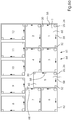
- Figure 6A and 6B show preferred embodiments of withdrawal schemes.
- Figure 6A and 6B show by way of example twelve product stacks 1 each from above. These were filed in the order 1 to 12.
- the gripping device 20 or the flange 26 is shown as a circle at one corner of each product stack.
- the two grippers 30 and 32 are shown at two corners each.
- the arrows 58 each show the directions in which the opened grippers are moved in order to release the product stack.
- the depositing of the product stacks 1 at the depositing positions 60 according to the respectively selected depositing scheme 61 allows the grippers 30 and 32 to be moved horizontally without collision to previously deposited product stacks.
- a so-called “chimney” 68 a free space in the settling scheme, can be created.
- a comparison of the Figures 6A and 6B shows that the withdrawal regimen can change.
- the depositing scheme is preferably changed in every new horizontal plane or position of a transport stack to be formed. This can improve the stability of the transport stack.
- Figure 7 shows a preferred embodiment of a transport stack generated by the "deposit" steps. A side view is shown.
- a first layer 63 of product stacks 1 is deposited on a transport pallet 62 in accordance with a first depositing scheme.
- An intermediate layer 67 is deposited over it.
- the robot can remove the intermediate layers from an adjacent stack of intermediate layers.
- the suction grippers 36 can be used for this purpose.
- a second layer 63 of product stacks 1 is deposited on the intermediate layer in accordance with the second, preferably different from the first, deposition scheme. It can be seen that the edges of the product stacks 1 can have a horizontal offset 69 relative to one another. In this way, the stability of the transport stack can be improved.
- the gripping device 20 can measure the vertical distance 65 by means of the sensor 66, and the digital computer 80 can use this measured value to control the collision-free movement of the gripping device.
- Figure 8 shows a preferred embodiment of a flow chart. Optional process steps are shown in dashed lines.
- the processing (100) can include the production of folded products 2.
- the transport (101) can include the transport of product stacks 1 in a transport direction 71.
- the separation (102) can include the separation of product stacks 1 in the transport direction 71.
- the stopping (103) can include stopping the product stack 1 at a pivoting device 40.
- the aligning (111) can include aligning the product stack, preferably about a vertical axis. Alignment elements 41 can be used for this purpose.
- the straightening (112) may include the straightening of the products 2.
- a straight pusher 42 can be used for this purpose.
- the shaking (113) can include shaking the product stack 1 and thus the products 2.
- the venting (114) can include venting the product stack 1. Ventilation can be done by shaking.
- the changing (115) can change a fanned-out product stack 1 into a non-fanned-out product stack.
- the alignment elements 41 can be used for this purpose. These can each be formed by a surface, e.g. a sheet metal with two folds.
- the transfer (120) can take place with the gripping device 20 and in particular with its grippers 30 and 32.
- When taking over the product stack can be transferred from the pivoting device 40 to the gripping device 20.
- the transfer can take place from side 3 or from side 4.
- Holding (121) can take place with the closed grippers 30 and 32.
- the movement or movement (130) is preferably carried out using the robot 10.
- the partial movement or partial movement (130a) and the partial movement or partial movement (130b) are preferably carried out using the robot 10.
- the calculation (131) is preferably carried out using the digital computer 80.
- the movement of the robot 10 can be calculated.
- the control (132) is preferably carried out using the digital computer 80.
- the movement of the robot 10 can be controlled.
- the robot arm 11 can be used to rotate (142).
- the sagging (150) can be achieved by an adjustable distance between the two grippers 30 and 32.
- the measurement (151) of the distance 65 and / or the height 65 can take place with the sensor 66.
- the laying down or stacking (152) can take place with the robot arm 11.
- a predetermined withdrawal scheme 61 can be taken into account.
Abstract
Ein erfindungsgemäßes Verfahren zum Bewegen eines Produktstapels mit einem Roboter, wobei der Roboter (10) einen Gelenkarm (11) und am Gelenkarm angeordnet wenigstens einen Greifer (30, 32) für den Produktstapel (1) umfasst und wobei der Produktstapel (1) wahlweise gewendet wird, zeichnet sich dadurch aus dass das Bewegen (130, 130a, 130b) an einer ausgewählten Absetzposition (60) von mehreren Absetzpositionen (60) eines vorgegebenen Absetzschemas (61) endet. Die Erfindung ermöglicht es in vorteilhafter Weise, Produktstapel automatisiert zu bewegen und insbesondere gewendet oder ungewendet abzusetzen.A method according to the invention for moving a product stack with a robot, wherein the robot (10) comprises an articulated arm (11) and at least one gripper (30, 32) arranged on the articulated arm for the product stack (1) and wherein the product stack (1) is optionally turned is characterized in that the movement (130, 130a, 130b) ends at a selected placement position (60) of several placement positions (60) of a predetermined placement scheme (61). The invention makes it possible in an advantageous manner to move product stacks in an automated manner and, in particular, to turn them over or to put them down.
Description
Die Erfindung betrifft ein Verfahren mit den Merkmalen des Oberbegriffs von Anspruch 1.The invention relates to a method having the features of the preamble of
Die Erfindung liegt auf dem technischen Gebiet der grafischen Industrie und dort insbesondere im Bereich des Handhabens (z.B. Greifen, Halten, Bewegen, Drehen, Wenden und/oder Ablegen) von Produktstapeln aus bevorzugt bedruckten und gefalzten flachen Produkten, bevorzugt aus Papier, Karton, Pappe, Kunststoff, Metall oder Verbundmaterial, mit einem Manipulator, insbesondere einem Roboter oder einem Gelenkarmroboter.The invention is in the technical field of the graphic industry and there in particular in the field of handling (e.g. gripping, holding, moving, rotating, turning and / or depositing) of product stacks of preferably printed and folded flat products, preferably made of paper, cardboard, cardboard , Plastic, metal or composite material, with a manipulator, in particular a robot or an articulated arm robot.
Es ist bekannt, Produktstapel, z.B. gefalzte Signaturen, von der Auslage einer Weiterverarbeitungsmaschine, z.B. einer Falzmaschine, händisch zu einer Palette zu transportieren und dort nach einem bekannten Absetzschema abzusetzen. Diese Tätigkeit stellt eine hohe körperliche Arbeitsbelastung dar, da etwa vier bis fünf Produktstapel pro Minute bewegt werden müssen. Es ist auch bekannt, hierzu einen Roboter mit einem Gelenkarm einzusetzen: beispielhaft sei das Produkt "CoBo-Stack" der Firma MBO Maschinenbau Oppenweiler Binder GmbH & Co. KG in Oppenweiler, Deutschland, genannt.It is known to manually transport product stacks, e.g. folded signatures, from the display of a further processing machine, e.g. a folding machine, to a pallet and deposit them there according to a known depositing scheme. This activity represents a high physical workload, since around four to five stacks of products have to be moved per minute. It is also known to use a robot with an articulated arm for this purpose: the product "CoBo-Stack" from MBO Maschinenbau Oppenweiler Binder GmbH & Co. KG in Oppenweiler, Germany, may be mentioned as an example.
Die
Die
Die
Die
Die
Es ist eine Aufgabe der vorliegenden Erfindung, eine Verbesserung gegenüber dem Stand der Technik zu schaffen, welche es insbesondere ermöglicht, Produktstapel automatisiert zu bewegen und insbesondere gewendet oder ungewendet abzusetzen.It is an object of the present invention to create an improvement over the prior art, which makes it possible, in particular, to move product stacks in an automated manner and, in particular, to turn them or turn them down.
Diese Aufgabe wird erfindungsgemäß durch ein Verfahren nach Anspruch 1 gelöst.This object is achieved according to the invention by a method according to
Vorteilhafte und daher bevorzugte Weiterbildungen der Erfindung ergeben sich aus den Unteransprüchen sowie aus der Beschreibung und den Zeichnungen.Advantageous and therefore preferred developments of the invention emerge from the subclaims as well as from the description and the drawings.
Die Erfindung betrifft ein Verfahren zum Bewegen eines Produktstapels mit einem Roboter, wobei der Roboter einen Gelenkarm und am Gelenkarm angeordnet wenigstens einen Greifer für den Produktstapel umfasst und wobei der Produktstapel wahlweise gewendet wird. Die Erfindung zeichnet sich dadurch aus, dass das Bewegen an einer ausgewählten Absetzposition von mehreren Absetzpositionen eines vorgegebenen Absetzschemas endet.The invention relates to a method for moving a product stack with a robot, the robot comprising an articulated arm and, arranged on the articulated arm, at least one gripper for the product stack and wherein the product stack is optionally turned. The invention is characterized in that moving on a selected placement position of several placement positions of a specified placement scheme ends.
Die Erfindung ermöglicht es in vorteilhafter Weise, Produktstapel automatisiert zu bewegen und insbesondere gewendet oder ungewendet abzusetzen.The invention makes it possible in an advantageous manner to move product stacks in an automated manner and, in particular, to turn them over or to put them down.
Der Produktstapel wird erfindungsgemäß und vorteilhafter Weise zu einer ausgewählten Absetzposition von mehreren Absetzpositionen eines vorgegebenen Absetzschemas bewegt und dort bevorzugt abgesetzt.According to the invention and in an advantageous manner, the product stack is moved to a selected depositing position from a plurality of depositing positions of a predetermined depositing scheme and is preferably deposited there.
Das Absetzschema kann in einem Digitalrechner oder einem mit diesem verbundenen Netzwerk gespeichert sein. Es kann eine Mehrzahl von Absetzschemata gespeichert sein, z.B. in einer Datenbank. Die Auswahl der Absetzposition (und/oder einer Abfolge von Absetzpositionen für aufeinander folgend zu bewegende Produktstapel) kann rechnergesteuert erfolgen. Beim Aufbau eines Transportstapels aus Produktstapeln kann für jede horizontale Lage ein Absetzschema gewählt werden, insbesondere können für zwei aufeinander folgende Lagen unterschiedliche Absetzschemata gewählt werden.The withdrawal scheme can be stored in a digital computer or a network connected to it. A plurality of dispatching schemes can be stored, e.g. in a database. The selection of the depositing position (and / or a sequence of depositing positions for product stacks to be moved one after the other) can be computer-controlled. When building a transport stack from product stacks, a depositing scheme can be selected for each horizontal position; in particular, different depositing schemes can be selected for two successive layers.
Der Begriff "wahlweise" meint, dass der Produktstapel entweder gewendet wird oder nicht gewendet wird. Die Wahl kann bevorzugt durch einen Digitalrechner erfolgen und kann von dem Digitalrechner insbesondere in Abhängigkeit von einem sogenannten Absetzmuster getroffen werden. Der Begriff "wahlweise" soll auch verdeutlichen, dass das Verfahren mit je einem Produktstapel mehrfach nacheinander durchgeführt werden kann und dass dabei wenigstens ein Produktstapel gewendet wird und wenigstens ein Produktstapel nicht gewendet wird.The term "optional" means that the product stack is either turned or is not turned. The selection can preferably be made by a digital computer and can be made by the digital computer in particular as a function of a so-called offset pattern. The term “optional” is also intended to make it clear that the method can be carried out several times in succession with one product stack each and that at least one product stack is turned over and at least one product stack is not turned over.
Im Folgenden werden bevorzugte Weiterbildungen der Erfindung (kurz: Weiterbildungen) beschrieben.Preferred developments of the invention (in short: further developments) are described below.
Eine Weiterbildung kann sich dadurch auszeichnen, dass der Produktstapel an der ausgewählten Absetzposition auf eine Unterlage, bevorzugt eine Palette, abgesetzt wird.A further development can be characterized in that the product stack is set down on a base, preferably a pallet, at the selected set-down position.
Eine Weiterbildung kann sich dadurch auszeichnen, dass der Produktstapel derart gehalten wird, dass der Produktstapel diagonal durchhängt und dass beim Absetzen des diagonal durchhängenden Produktstapels zunächst der Durchhang die Unterlage berührt.A further development can be characterized in that the product stack is held in such a way that the product stack sags diagonally and that when the diagonally sagging product stack is set down, the sag initially touches the base.
Eine Weiterbildung kann sich dadurch auszeichnen, dass das Absetzschema in einem Digitalrechner gespeichert ist oder über ein Netzwerk von einem anderen Digitalrechner auf den Digitalrechner geladen wird und dass das Bewegen durch den Digitalrechner gesteuert wird.A further development can be characterized in that the withdrawal scheme is stored in a digital computer or is loaded onto the digital computer from another digital computer via a network and that the movement is controlled by the digital computer.
Eine Weiterbildung kann sich dadurch auszeichnen, dass das Absetzschema vom Digitalrechner in Abhängigkeit von wenigstens einem der folgenden Parameter berechnet und/oder ausgewählt wird: Abmessungen des Produktstapels; Abmessungen der Unterlage; im Falle von gefalzten Produkten gebildeter Produktstapel: Lage der Falzkanten relativ zur Unterlage und/oder Aufbau der Falzkanten in Abhängigkeit von der Falzart.A further development can be characterized in that the depositing scheme is calculated and / or selected by the digital computer as a function of at least one of the following parameters: dimensions of the product stack; Dimensions of the base; Product stacks formed in the case of folded products: Position of the folded edges relative to the base and / or structure of the folded edges depending on the type of fold.
Eine Weiterbildung kann sich dadurch auszeichnen, dass nacheinander mehrere Produktstapel bewegt, wahlweise gewendet, wahlweise in der Horizontalen gedreht und an jeweils ausgewählten Absetzpositionen von mehreren Absetzpositionen des vorgegebenen Absetzschemas abgesetzt werden. Dabei kann ein rechnergesteuerter Roboter mit einem Gelenkarm und einer Greifeinrichtung zum Einsatz kommen.A further development can be characterized in that several product stacks are moved one after the other, optionally turned, optionally rotated horizontally and deposited at selected depositing positions from several depositing positions of the specified depositing scheme. A computer-controlled robot with an articulated arm and a gripping device can be used.
Eine Weiterbildung kann sich dadurch auszeichnen, dass der Produktstapel um einen effektiven Winkel α1 < > 180° geschwenkt wird und dass der Produktstapel anschließend um einen effektiven Winkel α2 = 180° - α1 geschwenkt oder um einen effektiven Winkel α2 = - α1 zurückgeschwenkt wird.A further development can be characterized in that the product stack is pivoted through an effective angle α1 <> 180 ° and that the product stack is then pivoted through an effective angle α2 = 180 ° - α1 or pivoted back through an effective angle α2 = - α1.
Der Produktstapel wird vorteilhafter Weise in zwei Schritten geschwenkt und dabei wahlweise gewendet. Im ersten Schritt erfolgt ein Schwenken um einen effektiven Winkel α1 < > 180°. Im zweiten Schritt erfolgt ein Schwenken um einen effektiven Winkel α2 = 180° - α1. Sind α1 und α2 z.B. beide 90°, so erfolgt ein Wenden um 180°. Sind α1 und α2 z.B. 90° und -90°, so erfolgt kein Wenden.The product stack is advantageously pivoted in two steps and optionally turned over. In the first step there is a pivoting through an effective angle α1 <> 180 °. In the second step, it is pivoted through an effective angle α2 = 180 ° - α1. For example, if α1 and α2 are both 90 °, then a turn is made by 180 °. If α1 and α2 are e.g. 90 ° and -90 °, no turning takes place.
Das 2-Schritt-Schwenkverfahren ermöglicht es in vorteilhafter Weise Zwischenschritte einzufügen, z.B. ein Rütteln und/oder Geradstoßen des Produktstapels. Weiterhin ermöglicht es das 2-Schritt-Schwenkverfahren in vorteilhafter Weise, die beiden Schritte an verschiedenen Positionen durchzuführen, z.B. indem der Roboter zwischendurch eine Bewegung ausführt. Weiterhin ermöglicht es das 2-Schritt-Schwenkverfahren in vorteilhafter Weise, die beiden Schritte unter Einsatz verschiedener Vorrichtungen durchzuführen, z.B. unter Einsatz des Roboters und unter Einsatz einer vom Roboter verschiedenen Schwenkeinrichtung.The 2-step swivel method makes it possible to insert intermediate steps, e.g. jogging and / or jogging the product stack. Furthermore, the 2-step swivel method advantageously enables the two steps to be carried out at different positions, e.g. by the robot executing a movement in between. Furthermore, the 2-step swivel method advantageously enables the two steps to be carried out using different devices, e.g. using the robot and using a swivel device different from the robot.
Der Begriff "effektiver Winkel" soll verdeutlichen, dass der Winkel unabhängig von der Art des Schwenkens ist. Ein effektiver Winkel von +90° kann demnach z.B. durch Schwenken um +90°, durch zweimaliges Schwenken um je +45° oder durch Schwenken um -270° erreicht werden. Anstatt "effektiver Winkel" kann auch einfach der Begriff "Winkel" verwendet werden.The term "effective angle" is intended to make it clear that the angle is independent of the type of pivoting. An effective angle of + 90 ° can therefore be achieved, for example, by swiveling by + 90 °, by swiveling twice by + 45 ° each or by swiveling by -270 °. Instead of “effective angle”, the term “angle” can also simply be used.
Eine Weiterbildung kann sich dadurch auszeichnen, dass das Schwenken um den effektiven Winkel α1 mit einer vom Roboter verschiedenen Schwenkeinrichtung erfolgt. Die Schwenkeinrichtung kann einem Ausleger einer Weiterverarbeitungsmaschine, insbesondere einer Falzmaschine, zugeordnet und insbesondere an diesem angeordnet sein. Sie kann einen schwenkbaren Greifer für den Produktstapel umfassen. Die Schwenkeinrichtung kann von einem Digitalrechner gesteuert sein. Die Schwenkeinrichtung schwenkt den Produktstapel bevorzugt um α1 = 90°.A further development can be characterized in that the pivoting through the effective angle α1 takes place with a pivoting device different from the robot. The pivoting device can be assigned to a boom of a further processing machine, in particular a folding machine, and in particular be arranged on this. It can comprise a pivotable gripper for the product stack. The swivel device can be controlled by a digital computer. The pivoting device pivots the product stack preferably by α1 = 90 °.
Eine Weiterbildung kann sich dadurch auszeichnen, dass das Schwenken um den effektiven Winkel α1 vor dem Bewegen erfolgt bzw. das Bewegen startet aus der geschwenkten Lage des Produktstapels heraus. Das Bewegen erfolgt bevorzugt mit dem Roboterarm.A further development can be characterized in that the pivoting by the effective angle α1 takes place before the movement or the movement starts from the pivoted position of the product stack out. The movement is preferably done with the robot arm.
Eine Weiterbildung kann sich dadurch auszeichnen, dass das Schwenken um den effektiven Winkel α1 um eine horizontale Achse erfolgt. Die Achse kann parallel zur Transportrichtung eines Auslegers einer Weiterverarbeitungsmaschine, insbesondere einer Falzmaschine, ausgerichtet sein. Vor dem Schwenken wird der Produktstapel bevorzugt ergriffen und gehalten.A further development can be characterized in that the pivoting takes place by the effective angle α1 about a horizontal axis. The axis can be aligned parallel to the transport direction of a boom of a further processing machine, in particular a folding machine. Before pivoting, the product stack is preferably gripped and held.
Eine Weiterbildung kann sich dadurch auszeichnen, dass der Produktstapel beim Schwenken um den effektiven Winkel α1 aus einer horizontalen Lage herausgeschwenkt wird. In der horizontalen Lage liegen die einzelnen Produkte des Produktstapels, z.B. gefalzte Signaturen, bevorzugt horizontal.A further development can be characterized in that the product stack is pivoted out of a horizontal position when pivoting through the effective angle α1. In the horizontal position, the individual products of the product stack, e.g. folded signatures, preferably lie horizontally.
Eine Weiterbildung kann sich dadurch auszeichnen, dass der Produktstapel beim Schwenken um den effektiven Winkel α1 in eine vertikale Lage hineingeschwenkt wird. In der vertikalen Lage "stehen" die einzelnen Produkte des Produktstapels bevorzugt.A further development can be characterized in that the product stack is pivoted into a vertical position when pivoting through the effective angle α1. The individual products of the product stack preferably "stand" in the vertical position.
Eine Weiterbildung kann sich dadurch auszeichnen, dass der Produktstapel außerhalb der horizontalen Lage ausgerichtet und/oder in einer Richtung geradgestoßen und/oder in zwei zueinander senkrechten Richtungen geradgestoßen und/oder gerüttelt und/oder belüftet wird und/oder dass ein aufgefächerter Produktstapel in einen nicht aufgefächerten Produktstapel verändert wird ("entfächern"). Währenddessen kann sich der Produktstapel in der Schwenkeinrichtung befinden, z.B. in deren Greifer. Der Greifer kann dabei leicht geöffnet sein, insbesondere für das Belüften. Eine Einrichtung für das Geradstoßen und/oder Entfächern kann zwei zueinander bewegliche, senkrecht stehende Flächen z.B. Bleche, bevorzugt mit seitlichen Abkantungen, umfassen. Diese Einrichtung kann vor dem Schwenken geöffnet sein und nach dem Schwenken geschlossen sein. Hierzu können die Flächen voneinander weg und aufeinander zu bewegt werden. Für das Rütteln können Pneumatikzylinder vorgesehen sein. Abschließend fährt die Einrichtung bzw. deren Flächen bevorzugt in eine offene Position, so dass der Produktstapel übernommen werden kann.A further development can be characterized in that the product stack is aligned outside of the horizontal position and / or pushed straight in one direction and / or pushed and / or jogged and / or ventilated in two mutually perpendicular directions and / or that a fanned-out product stack is not in one direction fanned out product stack is changed ("fan out"). Meanwhile, the product stack can be in the swivel device, for example in its gripper. The gripper can be slightly open, especially for ventilation. A device for straightening and / or fan-out can comprise two mutually movable, perpendicular surfaces, for example metal sheets, preferably with lateral bevels. This device can be opened before pivoting and closed after pivoting. For this purpose, the surfaces can be moved away from one another and towards one another. Pneumatic cylinders can be provided for shaking. Finally, the device or its surfaces preferably move into an open position so that the product stack can be taken over.
Eine Weiterbildung kann sich dadurch auszeichnen, dass der Produktstapel in der vertikalen Lage um eine vertikale Achse gedreht wird, bevorzugt um 180°. Dies ermöglicht es in vorteilhafter Weise, den Produktstapel in der vertikalen Lage sowohl beim wahlweisen Wenden als auch beim wahlweisen Nichtwenden von derselben Seite her zu ergreifen. Das Drehen kann mit der Schwenkeinrichtung erfolgen. Diese kann hierzu einen Drehantrieb umfassen. Der Drehantrieb kann von einem Digitalrechner gesteuert sein.A further development can be characterized in that the product stack is rotated in the vertical position about a vertical axis, preferably by 180 °. This makes it possible in an advantageous manner to grasp the product stack in the vertical position, both when optionally turning it over and when optionally not turning it over, from the same side. Rotation can be done with the swivel device. This can include a rotary drive for this purpose. The rotary drive can be controlled by a digital computer.
Eine Weiterbildung kann sich dadurch auszeichnen, dass die Übernahme des Produktstapels im Falle des Wendens von einer Seite des Produktstapels her erfolgt und dass die Übernahme des Produktstapels im Falle des Nichtwendens von derselben Seite des Produktstapels her erfolgt. Das Übernehmen von der einen oder der anderen Seite her kann mit einem Gelenkarm des Roboters durchgeführt werden. Die Auswahl der Seite kann rechnergesteuert erfolgen. Dabei kann ein vorgegebenes Absetzschema berücksichtigt werden.A further development can be characterized in that the product stack is taken over from one side of the product stack when it is turned and that the product stack is taken over from the same side of the product stack when it is not turned. The transfer from one side or the other can be carried out with an articulated arm of the robot. The side can be selected under computer control. A specified withdrawal scheme can be taken into account.
Eine Weiterbildung kann sich dadurch auszeichnen, dass der Roboter den Produktstapel in der vertikalen Lage übernimmt. Der Roboter und insbesondere dessen Greifer kann hierzu rechnergesteuert an den Produktstapel heranbewegt werden, z.B. von oben und/oder von einer Seite her.A further development can be characterized in that the robot takes over the product stack in the vertical position. The robot and in particular its gripper can be moved towards the product stack under computer control, e.g. from above and / or from one side.
Eine Weiterbildung kann sich dadurch auszeichnen, dass der Produktstapel in der vertikalen Lage bewegt wird, zumindest auf einer Teilstrecke der Bewegung. Entlang der Strecke der Bewegung kann die Lage des Produktstapel verändert werden, z.B. durch Schwenken (um eine horizontale Achse) und/oder durch Drehen (um eine vertikale Achse).A further development can be characterized in that the product stack is moved in the vertical position, at least over part of the movement. The position of the product stack can be changed along the path of the movement, e.g. by pivoting (about a horizontal axis) and / or rotating (about a vertical axis).
Eine Weiterbildung kann sich dadurch auszeichnen, dass der Roboter den Produktstapel von der Schwenkeinrichtung übernimmt und dann bewegt. Das Übernehmen und ebenso ein Halten des Produktstapels kann mit einer Greifeinrichtung des Roboters erfolgen. Das Bewegen kann durch ein Bewegen eines Gelenkarms des Roboters erfolgen. Der Roboter kann zusätzlich in der Horizontalen verschoben werden. Alle Aktionen des Roboters können bevorzugt rechnergesteuert erfolgen.A further development can be characterized in that the robot takes over the product stack from the pivoting device and then moves it. The product stack can be taken over and held using a gripping device of the robot. The movement can take place by moving an articulated arm of the robot. The robot can also be moved horizontally. All actions of the robot can preferably be computer-controlled.
Eine Weiterbildung kann sich dadurch auszeichnen, dass die Übernahme des Produktstapels im Falle des Wendens von einer Seite des Produktstapels her erfolgt und dass die Übernahme des Produktstapels im Falle des Nichtwendens von der gegenüberliegenden Seite des Produktstapels her erfolgt. Das Übernehmen von der einen oder der anderen Seite her kann mit einem Gelenkarm des Roboters durchgeführt werden. Eine Greifeinrichtung des Roboters kann dabei derart gedreht werden, dass ein Greifen von der einen Seite oder von der andren Seite her erfolgt. Die Auswahl der Seite kann rechnergesteuert erfolgen. Dabei kann ein vorgegebenes Absetzschema berücksichtigt werden.A further development can be characterized in that the product stack is taken over from one side of the product stack when it is turned and that the product stack is taken over from the opposite side of the product stack when it is not turned. The transfer from one side or the other can be carried out with an articulated arm of the robot. A gripping device of the robot can be rotated in such a way that gripping takes place from one side or from the other side. The side can be selected under computer control. A specified withdrawal scheme can be taken into account.
Eine Weiterbildung kann sich dadurch auszeichnen, dass das Schwenken um den effektiven Winkel α2 während des Bewegens oder zwischen zwei Teilbewegungen oder nach dem Bewegen erfolgt. Das Schwenken kann rechnergesteuert erfolgen. Dabei kann ein vorgegebenes Absetzschema berücksichtigt werden.A further development can be characterized in that the pivoting by the effective angle α2 takes place during the movement or between two partial movements or after the movement. The pivoting can be computer-controlled. A specified withdrawal scheme can be taken into account.
Eine Weiterbildung kann sich dadurch auszeichnen, dass das Schwenken um den effektiven Winkel a2 mit dem Roboter erfolgt. Das Schwenken kann durch entsprechendes Bewegen eines Gelenkarms des Roboters erfolgen und/oder kann durch eine Schwenkeinrichtung am Roboter bzw. an dessen Gelenkarm und/oder durch eine schwenkbare Greifeinrichtung am Roboter bzw. an dessen Gelenkarm erfolgen. Das Schwenken kann rechnergesteuert erfolgen.A further development can be characterized in that the pivoting takes place through the effective angle a2 with the robot. The pivoting can take place by moving an articulated arm of the robot accordingly and / or can take place by a pivoting device on the robot or on its articulated arm and / or by a pivotable gripping device on the robot or on its articulated arm. The pivoting can be computer-controlled.
Eine Weiterbildung kann sich dadurch auszeichnen, dass der Produktstapel beim Schwenken um den effektiven Winkel α2 in eine horizontale Lage zurückgeschwenkt wird. Der Produktstapel wird in diesem Fall nicht gewendet, d.h. ungewendet abgelegt.A further development can be characterized in that the product stack is pivoted back into a horizontal position when pivoting through the effective angle α2. In this case, the product stack is not turned over, i.e. it is deposited without being turned over.
Eine Weiterbildung kann sich dadurch auszeichnen, dass der Produktstapel in der horizontalen Lage abgelegt wird. Das Ablegen erfolgt bevorzugt auf eine Palette. Zum Ablegen können Greifer am Roboter gleichzeitig oder nacheinander geöffnet und seitlich weggefahren werden.A further development can be characterized in that the product stack is deposited in the horizontal position. They are preferably placed on a pallet. To put them down, grippers on the robot can be opened simultaneously or one after the other and moved away to the side.
Eine Weiterbildung kann sich dadurch auszeichnen, dass der Produktstapel vor dem Ablegen um eine vertikale Achse gedreht wird. Hierdurch kann die Ausrichtung des Produktstapels in der Horizontalen verändert werden, z.B. um effektiv 90° oder 180°. Das Drehen kann rechnergesteuert erfolgen. Dabei kann ein vorgegebenes Absetzschema berücksichtigt werden.A further development can be characterized in that the product stack is rotated about a vertical axis before being deposited. This allows the horizontal alignment of the product stack to be changed, e.g. by effectively 90 ° or 180 °. The turning can be computer-controlled. A specified withdrawal scheme can be taken into account.
Eine Weiterbildung kann sich dadurch auszeichnen, dass der effektive Winkel α1 = 90° ist und der effektive Winkel α2 = 90° ist und dass um α2 weitergeschwenkt wird. Beim Weiterschwenken erfolgt das Schwenken um α1 und das Schwenken um a2 bevorzugt in dieselbe Schwenkrichtung. Der Produktstapel wird hierbei "in Summe" gewendet.A further development can be distinguished by the fact that the effective angle α1 = 90 ° and the effective angle α2 = 90 ° and that it is pivoted further by α2. When pivoting further, the pivoting about α1 and the pivoting about a2 preferably take place in the same pivoting direction. The product stack is turned "in total".
Eine Weiterbildung kann sich dadurch auszeichnen, dass der effektive Winkel α1 = 90° ist und der effektive Winkel α2 = -90° ist und dass um α2 zurückgeschwenkt wird. Beim Zurückschwenken erfolgt das Schwenken um α1 und das Schwenken um α2 bevorzugt in entgegengesetzte Schwenkrichtungen. Der Produktstapel wird hierbei "in Summe" nicht gewendet.A further development can be characterized in that the effective angle α1 = 90 ° and the effective angle α2 = -90 ° and that it is pivoted back by α2. When pivoting back, the pivoting about α1 and the pivoting about α2 preferably take place in opposite pivoting directions. The product stack is not turned "in total".
Eine Weiterbildung kann sich dadurch auszeichnen, dass der Produktstapel während des Bewegens von wenigstens zwei Greifern gehalten wird.A further development can be characterized in that the product stack is held by at least two grippers while it is being moved.
Eine Weiterbildung kann sich dadurch auszeichnen, dass der Produktstapel während des Bewegens formschlüssig und/oder kraftschlüssig gehalten wird.A further development can be characterized in that the product stack is held in a form-fitting and / or force-fitting manner while it is moving.
Eine Weiterbildung kann sich dadurch auszeichnen, dass eine Seite des Produktstapels wenigstens vier Ecken aufweist und dass der Produktstapel während des Bewegens an sich diagonal gegenüberliegenden Ecken gehalten wird. Bei mehr als vier Ecken können z.B. solche Ecken ausgewählt werden, welche einen großen Abstand zueinander haben und/oder in guter Näherung sich diagonal gegenüber liegen.A further development can be characterized in that one side of the product stack has at least four corners and that the product stack is held at diagonally opposite corners during the movement. If there are more than four corners, for example, those corners can be selected that have a large distance from one another and / or are diagonally opposite one another to a good approximation.
Eine Weiterbildung kann sich dadurch auszeichnen, dass wahlweise zwei sich diagonal gegenüberliegende Ecken oder zwei andere sich diagonal gegenüberliegende Ecken gehalten werden. Die Auswahl der Ecken kann rechnergesteuert erfolgen. Dabei kann ein vorgegebenes Absetzschema berücksichtigt werden. Hierzu wird eine Greifeinrichtung am Roboterarm bevorzugt gedreht.A further development can be characterized in that either two diagonally opposite corners or two other diagonally opposite corners are held. The corners can be selected under computer control. It can be a prescribed withdrawal scheme must be taken into account. For this purpose, a gripping device on the robot arm is preferably rotated.
Eine Weiterbildung kann sich dadurch auszeichnen, dass der Produktstapel derart gehalten wird, dass der Produktstapel durchhängt. Hierzu kann der Abstand von Greifern des Roboters bis zu einem gewünschten oder vorgegebenen Durchhang bevorzugt rechnergesteuert verringert werden. Der Produktstapel kann aus gefalzten Papierbogen gebildet sein.A further development can be characterized in that the product stack is held in such a way that the product stack sags. For this purpose, the distance between the grippers of the robot can be reduced, preferably by computer control, up to a desired or predetermined sag. The product stack can be formed from folded sheets of paper.
Eine Weiterbildung kann sich dadurch auszeichnen, dass der Produktstapel derart gehalten wird, dass der Produktstapel diagonal durchhängt. Hierdurch kann der Produktstapel mit der Diagonale als "tiefstem Punkt" kontrolliert und sich selbst fixierend abgesetzt werden. Der Produktstapel kann hierzu an diagonal gegenüberliegenden Ecken gehalten werden.A further development can be characterized in that the product stack is held in such a way that the product stack sags diagonally. In this way, the product stack can be checked with the diagonal as the "lowest point" and set down in a self-locking manner. For this purpose, the product stack can be held at diagonally opposite corners.
Im Folgenden werden weitere bevorzugte Weiterbildung der Erfindung (kurz: Weiterbildungen) beschrieben.Further preferred further developments of the invention (in short: further developments) are described below.
Eine Weiterbildung kann sich dadurch auszeichnen, dass zwei Greifer zum Einsatz kommen und dass beim Ablegen bzw. Absetzen des Produktstapels die Greifer in der Horizontalen in zwei senkrecht zu einander liegenden Richtungen vom Produktstapel entfernt werden.A further development can be characterized in that two grippers are used and that when the product stack is laid down or set down, the grippers are removed horizontally from the product stack in two directions perpendicular to one another.
Eine Weiterbildung kann sich dadurch auszeichnen, dass beim Ablegen bzw. Absetzen des Produktstapels die Greifer in der Vertikalen öffnen. Dabei kann eine Greiferbacke des Greifers bewegt werden, bevorzugt kann eine oberhalb des Produktstapels befindliche Greiferbacke nach oben bewegt werden. Die andere Greiferbacke, bevorzugt jene unterhalb des Produktstapels, kann unbewegt sein.A further development can be distinguished by the fact that the grippers open vertically when the product stack is deposited or set down. A gripper jaw of the gripper can be moved, preferably a gripper jaw located above the product stack can be moved upwards. The other gripper jaw, preferably the one below the product stack, can be immobile.
Eine Weiterbildung kann sich dadurch auszeichnen, dass jeder Produktstapel zu einer jeweils derart ausgewählten Absetzposition des Absetzschemas bewegt wird, dass in der Absetzposition die Greifer kollisionsfrei zu bereits abgesetzten Produktstapeln in der Horizontalen vom Produktstapel entfernt werden.A further development can be characterized in that each product stack is moved to a respectively selected depositing position of the depositing scheme that in the Set-down position, the grippers can be removed from the product stack horizontally without collision to product stacks that have already been set down.
Im Folgenden werden weitere bevorzugte Weiterbildung der Erfindung (kurz: Weiterbildungen) beschrieben.Further preferred further developments of the invention (in short: further developments) are described below.
Eine Weiterbildung kann sich dadurch auszeichnen, dass das Bewegen des Produktstapels von einer Auslage einer Weiterverarbeitungsmaschine für Druckprodukte zu einer Palette oder zu einer von mehreren Paletten erfolgt. Im letzteren Fall ist ein Non-Stop-Betrieb möglich.A further development can be characterized in that the product stack is moved from a display of a further processing machine for printed products to a pallet or to one of several pallets. In the latter case, non-stop operation is possible.
Eine Weiterbildung kann sich dadurch auszeichnen, dass das Bewegen des Produktstapels von einer Auslage einer Weiterverarbeitungsmaschine für Druckprodukte, z.B. einer Falzmaschine, einem Sammelhefter oder einem Klebebinder, zu einer Palette oder zu einer von mehreren Paletten erfolgt.A further development can be characterized in that the product stack is moved from a display of a further processing machine for printed products, e.g. a folding machine, a saddle stitcher or an adhesive binder, to a pallet or to one of several pallets.
Eine Weiterbildung kann sich dadurch auszeichnen, dass die Produktstapel in der Auslage in eine Transportrichtung transportiert werden und in der Transportrichtung voneinander separiert werden. Der Transport kann auf einem Rollenförderer erfolgen. Zum Separieren können einzelne antreibbare Rollen entsprechend angetrieben oder gestoppt werden.A further development can be characterized in that the product stacks in the display are transported in one transport direction and are separated from one another in the transport direction. The transport can take place on a roller conveyor. For the separation, individual drivable rollers can be driven or stopped accordingly.
Eine Weiterbildung kann sich dadurch auszeichnen, dass der Roboter verschiebbar und an mehreren Positionen einer einzelnen Weiterverarbeitungsmaschine oder an mehreren Weiterverarbeitungsmaschinen einsetzbar ist. Der Roboter kann hierzu auf Rollen und/oder Schienen gelagert sein.A further development can be characterized in that the robot is displaceable and can be used in several positions of a single further processing machine or on several further processing machines. For this purpose, the robot can be mounted on rollers and / or rails.
Eine Weiterbildung kann sich dadurch auszeichnen, dass der Produktstapel von gefalzten und/oder gestanzten Druckprodukten gebildet ist.A further development can be characterized in that the product stack is formed from folded and / or punched printed products.
Eine Weiterbildung kann sich dadurch auszeichnen, dass mehrere Produktstapel - horizontal versetzt zueinander - und in mehreren horizontalen Ebenen übereinander zu einem Transportstapel auf einer Transportpalette übereinandergestapelt werden bzw. dass ein Transportstapel entsprechend gebildet oder aufgebaut wird. Die Auswahl des Versatzes und/oder der Ebenen kann rechnergesteuert erfolgen. Dabei kann ein vorgegebenes Absetzschema berücksichtigt werden.A further development can be characterized in that several product stacks - horizontally offset to one another - and in several horizontal planes one above the other to form a transport stack on a transport pallet are stacked or that a transport stack is formed or built up accordingly. The selection of the offset and / or the planes can be computer-controlled. A specified withdrawal scheme can be taken into account.
Eine Weiterbildung kann sich dadurch auszeichnen, dass ein am Roboter angeordneter Sensor die Höhe des Transportstapels erfasst. Der Sensor kann an einer Greifeinrichtung des Roboters angeordnet sein. Es können mehrere Sensoren angeordnet sein. Die Höhe kann absolut bestimmt werden, z.B. gemessen von der Oberkante einer Palette oder des Bodens, oder relativ als Abstand zum Sensor bestimmt werden.A further development can be characterized in that a sensor arranged on the robot detects the height of the transport stack. The sensor can be arranged on a gripping device of the robot. Several sensors can be arranged. The height can be determined absolutely, e.g. measured from the upper edge of a pallet or the floor, or it can be determined relative to the distance to the sensor.
Eine Weiterbildung kann sich dadurch auszeichnen, dass als Höhe ein einzelner Höhenwert, eine Menge von Höhenwerten an verschiedenen horizontalen Positionen oder ein Höhenprofil erfasst wird.A further development can be characterized in that a single height value, a set of height values at different horizontal positions or a height profile is recorded as the height.
Eine Weiterbildung kann sich dadurch auszeichnen, dass als Sensor ein Abstandssensor zum Messen der Höhe oder eine Kamera mit digitaler Bildverarbeitung zur Berechnung der Höhe aus dem Kamerabild verwendet wird.A further development can be characterized in that a distance sensor for measuring the height or a camera with digital image processing for calculating the height from the camera image is used as the sensor.
Eine Weiterbildung kann sich dadurch auszeichnen, dass der Roboterarm kollisionsfrei über einen erst teilweise aufgebauten Transportstapel bewegt wird, wobei der Digitalrechner die erfasste Höhe bei der Steuerung der Bewegung des Roboterarms berücksichtigt.A further development can be characterized in that the robot arm is moved without collision over an only partially built-up transport stack, the digital computer taking the detected height into account when controlling the movement of the robot arm.
Eine Weiterbildung kann sich dadurch auszeichnen, dass der Roboter einzelne Zwischenlagen von einem Stapel abnimmt und auf jeweiligen Ebenen ablegt. Die Zwischenlagen können aus Karton sein. Das Ablegen von Zwischenlagen kann rechnergesteuert erfolgen. Dabei kann ein vorgegebenes Absetzschema und/oder Stapelschema berücksichtigt werden.A further development can be characterized in that the robot removes individual intermediate layers from a stack and places them on the respective levels. The intermediate layers can be made of cardboard. The depositing of intermediate layers can be computer-controlled. A predefined depositing scheme and / or stacking scheme can be taken into account.
Eine Weiterbildung kann sich dadurch auszeichnen, dass die Zwischenlage saugend gehalten wird. Hierzu kann ein Sauggreifer an einer Greifeinrichtung des Roboters angeordnet sein. Es können mehrere solcher Sauggreifer zum Einsatz kommen.A further development can be characterized in that the intermediate layer is held in an absorbent manner. For this purpose, a suction gripper can be arranged on a gripping device of the robot. Several such suction pads can be used.
Eine Weiterbildung kann sich dadurch auszeichnen, dass das Bewegen vollautomatisch, in Abhängigkeit eines ausgewählten Absetzschemas und/oder Stapelschemas und in Abstimmung mit der Produktionsgeschwindigkeit wenigstens der Weiterverarbeitungsmaschine erfolgt.A further development can be characterized in that the movement takes place fully automatically, depending on a selected depositing scheme and / or stacking scheme and in coordination with the production speed of at least the further processing machine.
Eine Weiterbildung kann sich dadurch auszeichnen, dass das Bewegen des Roboterarms innerhalb einer geschützten Zone erfolgt.A further development can be characterized in that the robot arm is moved within a protected zone.
Eine Weiterbildung kann sich dadurch auszeichnen, dass zur Errichtung der geschützten Zone ein Gehäuse und/oder ein Zaun und/oder eine Lichtschranke und/oder eine Kameraüberwachung verwendet wird.A further development can be characterized in that a housing and / or a fence and / or a light barrier and / or camera monitoring is used to establish the protected zone.
Im Folgenden werden weitere bevorzugte Weiterbildungen der Erfindung (kurz: Weiterbildungen) beschrieben.Further preferred developments of the invention (in short: further developments) are described below.
Eine Weiterbildung des erfindungsgemäßen Verfahrens kann sich dadurch auszeichnen, dass eine Vorrichtung zum Bewegen eines Produktstapels mit einem Roboter verwendet wird, wobei der Roboter einen Gelenkarm umfasst, an welchem ein erster Greifer für den Produktstapel angeordnet ist. Das Verfahren zeichnet sich dadurch aus, dass am Gelenkarm eine Greifeinrichtung angeordnet ist, welche den ersten Greifer und einen zweiten Greifer umfasst, wobei der erste Greifer und der zweite Greifer relativ zueinander positioniert werden.A further development of the method according to the invention can be characterized in that a device is used for moving a product stack with a robot, the robot comprising an articulated arm on which a first gripper for the product stack is arranged. The method is characterized in that a gripping device is arranged on the articulated arm which comprises the first gripper and a second gripper, the first gripper and the second gripper being positioned relative to one another.
Die genannte Vorrichtung kann als solche eine weitere Erfindung darstellen:
Eine Vorrichtung zum Bewegen eines Produktstapels mit einem Roboter, wobei der Roboter einen Gelenkarm umfasst, an welchem ein erster Greifer für den Produktstapel angeordnet ist. Die Vorrichtung zeichnet sich dadurch aus, dass am Gelenkarm eine Greifeinrichtung angeordnet ist, welche den ersten Greifer und einen zweiten Greifer umfasst, wobei der erste Greifer und der zweite Greifer relativ zueinander positionierbar sind.The device mentioned can, as such, represent a further invention:
A device for moving a product stack with a robot, the robot comprising an articulated arm on which a first gripper for the product stack is arranged. The device is characterized in that a gripping device is arranged on the articulated arm which comprises the first gripper and a second gripper, the first gripper and the second gripper being positionable relative to one another.
Die Vorrichtung als solche oder deren Verwendung ermöglicht es in vorteilhafter Weise, Produktstapel automatisiert zu bewegen und insbesondere gewendet oder ungewendet abzusetzen.The device as such or its use makes it possible in an advantageous manner to move product stacks in an automated manner and, in particular, to turn them over or to put them down.
Ein besonderer Vorteil kann darin gesehen werden, dass Produktstapel verschiedener Größen oder Formate bewegt und insbesondere wahlweise gewendet oder ungewendet abgesetzt werden können.A particular advantage can be seen in the fact that product stacks of different sizes or formats can be moved and, in particular, optionally turned or deposited.
Im Folgenden werden weitere bevorzugte Weiterbildungen der Erfindung (kurz: Weiterbildungen) beschrieben. Diese Weiterbildungen können auch bevorzugte Weiterbildungen der weiteren Erfindung, der Vorrichtung als solcher, darstellen.Further preferred developments of the invention (in short: further developments) are described below. These developments can also represent preferred developments of the further invention, the device as such.
Eine Weiterbildung kann sich dadurch auszeichnen, dass die beiden Greifer auf vorgegebene Formate von Produkten oder Produktstapeln positionierbar sind, bevorzugt rechnergesteuert. Die Greifer können für das Positionieren bewegbar, bevorzugt linear bewegbar, sein. Das Positionieren erfolgt bevorzugt rechnergesteuert.A further development can be characterized in that the two grippers can be positioned on predetermined formats of products or product stacks, preferably computer-controlled. The grippers can be movable, preferably linearly movable, for positioning. The positioning is preferably computer-controlled.
Eine Weiterbildung kann sich dadurch auszeichnen, dass die beiden Greifer auf die beiden Enden einer ausgewählten Diagonalen eines ausgewählten Formats positionierbar sind. Das Positionieren erfolgt bevorzugt rechnergesteuert.A further development can be characterized in that the two grippers can be positioned on the two ends of a selected diagonal of a selected format. The positioning is preferably computer-controlled.
Eine Weiterbildung kann sich dadurch auszeichnen, dass der erste Greifer als erster Zangengreifer mit einem ersten Paar Greiferbacken ausgebildet ist und dass der zweite Greifer als zweiter Zangengreifer mit einem zweiten Paar Greiferbacken ausgebildet ist. Eine Weiterbildung kann sich dadurch auszeichnen, dass beide Paare Greiferbacken jeweils einen unbeweglichen Greiferbacken und jeweils einen relativ zum unbeweglichen Greiferbacken linear beweglichen Greiferbacken umfassen. Es können Linearantriebe vorgesehen sein, bevorzugt elektrische mit Gewindespindel. Die unbeweglichen Greiferbacken sind selbstredend nicht gänzlich unbeweglich: sie können durch die Bewegung des Roboters, der Greifeinrichtung und/oder der Greifer bewegt werden. Die unbeweglichen Greiferbacken sind lediglich beim Öffnen und Schließen der Greifer unbewegt oder im Verhältnis zu den beweglichen Greiferbacken nur unwesentlich bewegt.A further development can be characterized in that the first gripper is designed as a first pincer gripper with a first pair of gripper jaws and that the second gripper is designed as a second pincer gripper with a second pair of gripper jaws. A further development can be characterized in that both pairs of gripper jaws each comprise an immovable gripper jaw and in each case a gripper jaw that is linearly movable relative to the immovable gripper jaw. Linear drives can be provided, preferably electrical ones with a threaded spindle. The immovable gripper jaws are of course not completely immobile: they can be moved by the movement of the robot, the gripping device and / or the gripper. The immovable gripper jaws are only immobile when the grippers are opened and closed or are only moved insignificantly in relation to the movable gripper jaws.
Eine Weiterbildung kann sich dadurch auszeichnen, dass die unbeweglichen Greiferbacken jeweils ein sich horizontal erstreckendes Auflageelement und jeweils wenigstens ein sich vertikal erstreckendes Anschlagelement umfassen.A further development can be characterized in that the immovable gripper jaws each comprise a horizontally extending support element and in each case at least one vertically extending stop element.
Eine Weiterbildung kann sich dadurch auszeichnen, dass beide unbeweglichen Greiferbacken jeweils eine sich horizontal erstreckende Auflagefläche als Auflageelement und jeweils zwei sich vertikale erstreckende und zueinander senkrechte Anschlagflächen als Anschlagelemente umfassen. Alle Flächen können senkrecht aufeinander stehen.A further development can be characterized in that both immovable gripper jaws each comprise a horizontally extending support surface as a support element and two vertically extending and mutually perpendicular stop surfaces as stop elements. All surfaces can be perpendicular to each other.
Eine Weiterbildung kann sich dadurch auszeichnen, dass der Produktstapel von den Greiferbacken kraftschlüssig und/oder formschlüssig gehalten wird.A further development can be characterized in that the product stack is held by the gripper jaws in a force-fitting and / or form-fitting manner.
Eine Weiterbildung kann sich dadurch auszeichnen, dass an der Greifeinrichtung wenigstens eine Blaseinrichtung angeordnet ist, welche beim Ablegen des Produktstapels Luft unter den Produktstapel bläst.A further development can be characterized in that at least one blowing device is arranged on the gripping device, which blows air under the product stack when the product stack is deposited.
Eine Weiterbildung kann sich dadurch auszeichnen, dass an der Greifeinrichtung wenigstens ein weiterer Greifer angeordnet ist, welcher als Sauggreifer für Zwischenlagen ausgebildet ist. Der Sauggreifer kann zum saugenden Ergreifen und Halten rechnergesteuert mit Saugluft beaufschlagbar sein.A further development can be characterized in that at least one further gripper, which is designed as a suction gripper for intermediate layers, is arranged on the gripping device. The suction gripper can be supplied with suction air in a computer-controlled manner for gripping and holding by suction.
Eine Weiterbildung kann sich dadurch auszeichnen, dass an der Greifeinrichtung wenigstens ein Abstandssensor und/oder wenigstens eine Kamera angeordnet ist.A further development can be characterized in that at least one distance sensor and / or at least one camera is arranged on the gripping device.
Eine Weiterbildung kann sich dadurch auszeichnen, dass die Greifeinrichtung einen ersten Tragarm umfasst, an welchem der erste Greifer linear in der Längsrichtung des ersten Tragarms beweglich angeordnet ist.A further development can be characterized in that the gripping device comprises a first support arm, on which the first gripper is arranged to be linearly movable in the longitudinal direction of the first support arm.
Eine Weiterbildung kann sich dadurch auszeichnen, dass die Greifeinrichtung einen zweiten Tragarm umfasst, an welchem der zweite Greifer linear in der Längsrichtung des zweiten Tragarms beweglich angeordnet ist.A further development can be characterized in that the gripping device comprises a second support arm, on which the second gripper is arranged so as to be linearly movable in the longitudinal direction of the second support arm.
Für das Bewegen der Greifer entlang der Tragarme kann jeweils ein Linearantrieb am Tragarm vorgesehen sein, bevorzugt ein elektrischer mit Gewindespindel. Der Linearantrieb kann elektrisch sein. Der Tragarm kann eine Länge aufweisen, welche mit einem zu bewegenden Produktstapel von maximalem Format korreliert.For moving the grippers along the support arms, a linear drive can be provided on the support arm, preferably an electric one with a threaded spindle. The linear drive can be electric. The support arm can have a length which correlates with a maximum format product stack to be moved.
Eine Weiterbildung kann sich dadurch auszeichnen, dass der erste Tragarm und der zweite Tragarm senkrecht zueinander an der Greifeinrichtung angeordnet sind. Die Tragarme können ein X-Y-Achsensystem für formateinstellbare Greifer bilden. Bewegliche Greiferbacken der Greifer können die dazu senkrechte Z-Achse bilden.A further development can be characterized in that the first support arm and the second support arm are arranged perpendicular to one another on the gripping device. The support arms can form an X-Y axis system for size adjustable grippers. Movable gripper jaws of the grippers can form the perpendicular Z-axis.
Eine Weiterbildung kann sich dadurch auszeichnen, dass die beiden linear beweglichen Greiferbacken senkrecht zum jeweiligen Tragarm beweglich sind.A further development can be characterized in that the two linearly movable gripper jaws can be moved perpendicular to the respective support arm.
Eine Weiterbildung kann sich dadurch auszeichnen, dass die Greifeinrichtung am Roboterarm um eine Drehachse drehbar angeordnet ist. Die Drehachse dient bevorzugt dem Drehen des Produktstapels um eine vertikale Achse und/oder dem Absetzen eines in der Horizontalen gedrehten Produktstapels.A further development can be characterized in that the gripping device is arranged on the robot arm so that it can rotate about an axis of rotation. The axis of rotation is preferably used to rotate the product stack about a vertical axis and / or to set down a product stack that has been rotated horizontally.
Eine Weiterbildung kann sich dadurch auszeichnen, dass die Greifeinrichtung am Roboterarm um eine zur Drehachse senkrechte Schwenkachse schwenkbar angeordnet ist. Die Schwenkachse dient bevorzugt dem Schwenken des Produktstapels um eine horizontale Achse und/oder dem Absetzen eines bezüglich der Horizontalen wahlweise gewendeten oder ungewendeten Produktstapels.A further development can be characterized in that the gripping device is arranged on the robot arm so as to be pivotable about a pivot axis perpendicular to the axis of rotation. The pivot axis is preferably used to pivot the product stack about a horizontal axis and / or to set down a product stack that is either turned or not turned with respect to the horizontal.
Eine Weiterbildung kann sich dadurch auszeichnen, dass der Gelenkarm sechs Achsen umfasst, bevorzugt Drehachsen.A further development can be characterized in that the articulated arm comprises six axes, preferably axes of rotation.
Eine Weiterbildung kann sich dadurch auszeichnen, dass der Roboter relativ zu einer oder mehreren, Produktstapel erzeugenden Weiterverarbeitungsmaschine bzw. -maschinen horizontal verschiebbar ist, z.B. auf Schienen oder auf Rollen.A further development can be characterized in that the robot can be moved horizontally relative to one or more further processing machines or machines that generate product stacks, e.g. on rails or on rollers.
Die in den obigen Abschnitten Technisches Gebiet und Erfindung, in den diversen obigen Abschnitten zu den Weiterbildungen sowie im folgenden Abschnitt Ausführungsbeispiele offenbarten Merkmale und Merkmalskombinationen stellen - in beliebiger Kombination miteinander - weitere vorteilhafte Weiterbildungen der Erfindung dar.The features and combinations of features disclosed in the above sections Technical Field and Invention, in the various sections above on the developments and in the following section, exemplary embodiments, represent - in any combination with one another - further advantageous developments of the invention.
Alternativ zu dem genannten 2-Schritt-Schwenkverfahren kann die Aufgabe mit einem Schwenkverfahren in nur einem Schritt gelöst werden. Dabei wird der Produktstapel für das wahlweise Wenden in horizontaler Ausrichtung mit der Greifeinrichtung eines Gelenkarmroboters bevorzugt von unten ergriffen und um einen effektiven Winkel von 180° geschwenkt, z.B. während es Bewegens zur Palette. Falls wahlweise nicht gewendet werden soll, so kann der Produktstapel in horizontaler Ausrichtung bevorzugt von oben ergriffen werden.As an alternative to the mentioned 2-step pivoting method, the task can be achieved with a pivoting method in just one step. The product stack is preferably gripped from below for the optional turning in a horizontal orientation with the gripping device of an articulated arm robot and pivoted through an effective angle of 180 °, e.g. while it is moving towards the pallet. If, alternatively, it should not be turned, the product stack can be gripped in a horizontal orientation, preferably from above.
Die
Eine nur teilweise dargestellte Weiterverarbeitungsmaschine 70 an einer Position 74, bevorzugt eine Falzmaschine, produziert Druckprodukte 2, bevorzugt bedruckte und/oder gefalzte Signaturen 2, welche in Form von Produktstapeln 1 auf einer Auslage 72 in eine Transportrichtung 71 bewegt z.B. gefördert werden. Die Aktion der Auslage, insbesondere das Fördern, kann vom Digitalrechner 80 gesteuert werden. Ein Produktstapel umfasst bevorzugt eine Vielzahl übereinanderliegender Produkte.A further processing
Ein Digitalrechner 80, welcher bevorzugt mit einem Netzwerk 81 in Verbindung steht, kann die Weiterverarbeitungsmaschine 70 und optional weitere Maschinen steuern, z.B. Auftragsdaten für die Produktherstellung zur Verfügung stellen. Auftragsdaten können über das Netzwerk bereitgestellt werden.A
Die Auslage 72 kann die Produktstapel 1 in eine geschützte Zone 73 bewegen. Ein Roboter 10 kann innerhalb dieser Zone angeordnet sein, welcher bevorzugt einen Gelenkarm 11 mit mehreren Achsen 12, z.B. sechs Achsen, umfasst. Der Roboter kann ein üblicher Industrieroboter sein.The
Am Roboter 10, bevorzugt am Ende von dessen Gelenkarm 11 bzw. "Hand", ist eine Greifeinrichtung 20 angeordnet. Die Greifeinrichtung kann Produktstapel 1 ergreifen, halten und im Raum, bevorzugt ausschließlich innerhalb der geschützten Zone, von der Auslage 72 wegbewegen. Die Bewegung 15 bewegt den Produktstapel 1 entlang einer Raumkurve zu einer Transportpalette 62. Dort wird der Produktstapel abgelegt und dabei bevorzugt entsprechend einem Absetzmuster 61 an einer Absetzposition 60 abgesetzt. Bevorzugt können mehrere, vom Roboter erreichbare Paletten vorgesehen sein. Die Bewegung kann mehrere Teilbewegungen 16 umfassen. Zwischen zwei Teilbewegungen kann die Greifeinrichtung z.B. gedreht und/oder geschwenkt werden. Das Drehen und/oder Schwenken kann auch während des Bewegens erfolgen.A
Am Ende der Auslage 72 ist bevorzugt eine Schwenkeinrichtung 40 angeordnet. Diese kann die Produktstapel 1 aus der Horizontalen 50 bzw. einer horizontalen Ebene 53 bzw. der horizontalen Lage 52 in die Vertikale 54 bzw. vertikale Ebene 57 bzw. die vertikale Lage 56 schwenken. Die Schwenkeinrichtung kann zwei bevorzugt horizontal bewegliche Ausrichtelemente 41 und/oder Geradstoßer 42 für den Produktstapel umfassen. Diese können als Flächen, z.B. Bleche ausgebildet sein.A pivoting
Die Aktion, insbesondere die Bewegung 15 und/oder 16, des Roboters 10 und/oder die Aktion, insbesondere das Schwenken, der Schwenkeinrichtung, kann vom Digitalrechner 80 gesteuert werden.The action, in particular the
Die Schwenkeinrichtung 40 umfasst bevorzugt Greifer 43, z.B. relativ zueinander bewegliche Stangen, bevorzugt eine Stange (schließender "Niederhalter") auf einer Seite des Produktstapels 1 und drei Stangen auf dessen anderer Seite. Die Schwenkeinrichtung und/oder deren Greifer können um eine horizontale Achse 51 geschwenkt werden. Die Greifer, welche sich in
Im Vergleich zwischen den
Die Schwenkeinrichtung kann optional drehbar ausgeführt sein und somit um eine vertikale Achse 55 gedreht werden. Der Produktstapel kann bevorzugt um 180° gedreht werden. Bei dieser Option kann der Roboter 1 den geschwenkten Produktstapel 1 immer von derselben Seite her ergreifen, bevorzugt von der Seite 3 bzw. der Vorderseite her.The pivoting device can optionally be designed to be rotatable and thus rotated about a
Die Greifeinrichtung 20 umfasst bevorzugt zwei Tragarme: einen ersten Tragarm 21 und einen zweiten Tragarm 23. Die Tragarme stehen bevorzugt senkrecht zueinander. Am ersten Tragarm ist ein erster Greifer 30 bevorzugt in eine erste Längsrichtung 22 beweglich angeordnet. Am zweiten Tragarm ist ein zweiter Greifer 32 bevorzugt in eine zweite Längsrichtung 24 beweglich angeordnet. Die Greifer können für deren formatabhängige Verstellung von Linearantrieben 25 angetrieben sein.The
Der erste Greifer 30 umfasst bevorzugt ein erstes Paar Greiferbacken 31 mit einem unbeweglichen Greiferbacken 31a und einem beweglichen Greiferbacken 31b. Der bewegliche Greiferbacken kann von einem Linearantrieb 37 angetrieben sein. Der zweite Greifer 32 umfasst bevorzugt ein zweites Paar Greiferbacken 33 mit einem unbeweglichen Greiferbacken 33a und einem beweglichen Greiferbacken 33b. Der bewegliche Greiferbacken kann von einem Linearantrieb 37 angetrieben sein. Die unbeweglichen Greiferbacken können jeweils ein Auflageelement 34, bevorzugt eine Auflagefläche, umfassen. Die beweglichen Greiferbacken dienen dem Öffnen und Schließen der Greifer.The
Die Greifer 30 und 32 ergreifen den Produktstapel 1 aus Produkten 2 bevorzugt an dessen Ecken 5 und besonders bevorzugt an sich diagonal (siehe Diagonale 7 in
Im gezeigten Beispiel der
Im gezeigten Beispiel der
Im Vergleich zwischen den
Im gezeigten Beispiel der
Im gezeigten Beispiel der
Im Vergleich zwischen den
Ob der Produktstapel 1 von der Seite 3 oder von der Seite 4 her ergriffen wird und ob dabei das eine Paar Ecken 5 oder das andere Paar Ecken 5 ergriffen wird, hängt davon ab, wie der Produktstapel abgelegt werden soll: ob er gewendet oder ungewendet und ob er gedreht oder ungedreht abgelegt werden soll. Dies wiederum hängt von einem ausgewählten Absetzschema und der jeweiligen Absetzposition innerhalb des Schemas ab. Der Digitalrechner 80 steuert das Ergreifen und somit die passende Aktion des Roboters 10 entsprechend dem Absetzschema und der Absetzposition. Dabei werden die Seite und die Ecken entsprechend gewählt.Whether the
Nach dem Ergreifen und während des Bewegens 130, insbesondere zwischen zwei Teilbewegungen 130a und 130b, und bevorzugt vor dem Ablegen (Verfahrensschritt 152) wird der Produktstapel 1 um den effektiven Winkel a2 geschwenkt, entweder weitergeschwenkt (Verfahrensschritt 122) oder zurückgeschwenkt (Verfahrensschritt 123). Durch das Weiterschwenken wird der Produktstapel bevorzugt gewendet abgelegt (Verfahrensschritt Wenden 140); durch das Zurückschwenken bevorzugt ungewendet abgelegt (Verfahrensschritt Nichtwenden 141).After gripping and during the movement 130, in particular between two partial movements 130a and 130b, and preferably before being deposited (method step 152), the
In
An jeweils einer Ecke jedes Produktstapels ist die Greifeinrichtung 20 bzw. der Flansch 26 als Kreis dargestellt. An jeweils zwei Ecken sind die beiden Greifer 30 und 32 dargestellt. Die Pfeile 58 zeigen jeweils die Richtungen, in die die geöffneten Greifer bewegt werden, um den Produktstapel freizugeben.The
Das Ablegen der Produktstapel 1 an den Absetzpositionen 60 nach dem jeweils ausgewählten Absetzschema 61 erlaubt es, die Greifer 30 und 32 in der Horizontalen kollisionsfrei zu bereits zuvor abgelegten Produktstapeln zu bewegen.The depositing of the
Wie in den
Ein Vergleich der
Auf einer Transportpalette 62 ist eine erste Lage 63 von Produktstapeln 1 entsprechend einem ersten Absetzschema abgelegt. Darüber ist eine Zwischenlage 67 abgelegt. Die Zwischenlagen können vom Roboter von einem benachbarten Zwischenlagenstapel entnommen werden. Hierzu können die Sauggreifer 36 verwendet werden. Auf der Zwischenlage ist eine zweite Lage 63 von Produktstapeln 1 entsprechend dem zweiten, bevorzugt zum ersten verschiedenen Absetzschema abgelegt. Es ist erkennbar, dass die Kanten der Produktstapel 1 zueinander einen horizontalen Versatz 69 aufweisen können. Auf diese Weise kann die Stabilität des Transportstapels verbessert werden.A
Die Greifeinrichtung 20 kann beim Annähern an den Transportstapel 64 mittels des Sensors 66 den vertikalen Abstand 65 messen und der Digitalrechner 80 kann mit diesem Messwert die kollisionsfreie Bewegung der Greifeinrichtung steuern.When approaching the
Das Verarbeiten (100) kann das Herstellen von gefalzten Produkten 2 umfassen.The processing (100) can include the production of folded
Das Transportieren (101) kann das Transportieren von Produktstapeln 1 in eine Transportrichtung 71 umfassen.The transport (101) can include the transport of
Das Separieren (102) kann das Separieren von Produktstapeln 1 in Transportrichtung 71 umfassen.The separation (102) can include the separation of
Das Anhalten (103) kann das Anhalten des Produktstapels 1 bei einer Schwenkeinrichtung 40 umfassen.The stopping (103) can include stopping the
Das Schwenken (110) kann das Schwenken des Produktstapels 1 mit einer Schwenkeinrichtung 40 umfassen, insbesondere um α1 = 90°.The pivoting (110) can comprise the pivoting of the
Das Ausrichten (111) kann das Ausrichten des Produktstapel umfassen, bevorzugt um eine vertikale Achse. Hierzu können Ausrichtelemente 41 verwendet werden.The aligning (111) can include aligning the product stack, preferably about a vertical axis. Alignment elements 41 can be used for this purpose.
Das Geradstoßen (112) kann das Geradstoßen der Produkte 2 umfassen. Hierzu kann ein Geradstoßer 42 verwendet werden.The straightening (112) may include the straightening of the
Das Rütteln (113) kann das Rütteln des Produktstapels 1 und somit der Produkte 2 umfassen.The shaking (113) can include shaking the
Das Belüften (114) kann das Belüften des Produktstapels 1 umfassen. Das Belüften kann durch das Rütteln erfolgen.The venting (114) can include venting the
Das Verändern (115) kann einen aufgefächerten Produktstapel 1 in einen nicht aufgefächerten Produktstapel verändern. Hierzu können die Ausrichtelemente 41 verwendet werden. Diese können jeweils von einer Fläche, z.B. einem Blech mit zwei Abkantungen gebildet sein.The changing (115) can change a fanned-out
Das Übernehmen (120) kann mit der Greifeinrichtung 20 und insbesondere mit deren Greifern 30 und 32 erfolgen. Beim Übernehmen kann der Produktstapel von der Schwenkeinrichtung 40 an die Greifeinrichtung 20 übergeben werden. Das Übernehmen kann von der Seite 3 her oder von der Seite 4 her erfolgen.The transfer (120) can take place with the
Das Halten (121) kann mit den geschlossenen Greifern 30 und 32 erfolgen.Holding (121) can take place with the
Das Weiterschwenken (122) kann mit dem Roboterarm 11 erfolgen, insbesondere um α2 = 90°.The further pivoting (122) can take place with the
Das Zurückschwenken (123) kann mit dem Roboterarm 11 erfolgen, insbesondere um a2 = -90°.The pivoting back (123) can take place with the
Es wird bevorzugt in Abhängigkeit von einem Absetzschema entweder weitergeschwenkt oder zurückgeschwenkt.It is preferably either swiveled further or swiveled back depending on a deposition scheme.
Das Bewegen bzw. die Bewegung (130) erfolgt bevorzugt unter Einsatz des Roboters 10. Das Teilbewegen bzw. Teilbewegung (130a) und das Teilbewegen bzw. Teilbewegung (130b) erfolgt bevorzugt unter Einsatz des Roboters 10.The movement or movement (130) is preferably carried out using the
Das Berechnen (131) erfolgt bevorzugt unter Einsatz des Digitalrechners 80. Es kann die Bewegung des Roboters 10 berechnet werden.The calculation (131) is preferably carried out using the
Das Steuern (132) erfolgt bevorzugt unter Einsatz des Digitalrechners 80. Es kann die Bewegung des Roboters 10 gesteuert werden.The control (132) is preferably carried out using the
Das Wenden (140) kann mit dem Roboterarm 11 erfolgen, insbesondere um α1+α2 = 180°.The turning (140) can take place with the
Das Nichtwenden (141) kann mit dem Roboterarm 11 erfolgen, insbesondere um α1+α2 = 0°.The non-turning (141) can take place with the
Das Drehen (142) kann mit dem Roboterarm 11 erfolgen.The
Das Durchhängen lassen (150) kann durch einen einstellbaren Abstand der beiden Greifer 30 und 32 zueinander erreicht werden.The sagging (150) can be achieved by an adjustable distance between the two
Das Messen (151) des Abstands 65 und/oder der Höhe 65 kann mit dem Sensor 66 erfolgen.The measurement (151) of the
Das Ablegen bzw. Übereinanderstapeln (152) kann mit dem Roboterarm 11 erfolgen.The laying down or stacking (152) can take place with the
Dabei kann insbesondere ein vorgegebenes Absetzschema 61 berücksichtigt werden.In particular, a
- 11
- ProduktstapelProduct stack
- 22
- Druckprodukte, insbesondere gefalzte DruckproduktePrinted products, in particular folded printed products
- 33
- Seiteside
- 44th
- gegenüberliegende Seiteopposite side
- 55
- EckenCorners
- 66th
- sich diagonal gegenüberliegende Eckendiagonally opposite corners
- 77th
- Diagonalediagonal
- 88th
- durchhängende Diagonalesagging diagonal
- 1010
- Vorrichtung, insbesondere RoboterDevice, especially robot
- 1111
- Roboterarm bzw. GelenkarmRobotic arm or articulated arm
- 1212th
- Achsenaxles
- 1313th
- DrehachseAxis of rotation
- 1414th
- SchwenkachseSwivel axis
- 1515th
- Bewegung bzw. StreckeMovement or distance
- 1616
- Teilbewegung bzw. TeilstreckePartial movement or partial distance
- 2020th
- GreifeinrichtungGripping device
- 2121
- erster Tragarmfirst support arm
- 2222nd
- erste Längsrichtungfirst longitudinal direction
- 2323
- zweiter Tragarmsecond support arm
- 2424
- zweite Längsrichtungsecond longitudinal direction
- 2525th
- Linearantrieblinear actuator
- 2626th
- Flanschflange
- 3030th
- erster Greifer, insbesondere Zangengreiferfirst gripper, in particular pincer gripper
- 3131
- erstes Paar Greiferbackenfirst pair of gripper jaws
- 31a31a
- unbeweglicher Greiferbackenimmovable gripper jaw
- 31b31b
- beweglicher Greiferbackenmovable gripper jaw
- 3232
- zweiter Greifer, insbesondere Zangengreifersecond gripper, in particular pincer gripper
- 3333
- zweites Paar Greiferbackensecond pair of gripper jaws
- 33a33a
- unbeweglicher Greiferbackenimmovable gripper jaw
- 33b33b
- beweglicher Greiferbackenmovable gripper jaw
- 3434
- Auflageelement, insbesondere AuflageflächeSupport element, in particular support surface
- 3535
- Anschlagelemente, insbesondere zwei AnschlagsflächenStop elements, in particular two stop surfaces
- 3636
- weiterer Greifer, insbesondere Sauggreiferfurther grippers, in particular suction grippers
- 3737
- Linearantrieblinear actuator
- 3838
- Bewegung beim Öffnen/Schließen der GreiferMovement when opening / closing the grippers
- 3939
- BlaseinrichtungBlower
- 4040
- SchwenkeinrichtungSwivel device
- 4141
- AusrichtelementeAlignment elements
- 4242
- GeradstoßerStraight pusher
- 4343
- GreiferGrapple
- 5050
- Horizontalehorizontal
- 5151
- horizontale Achsehorizontal axis
- 5252
- horizontale Lagehorizontal position
- 5353
- horizontale Ebenehorizontal plane
- 5454
- Vertikalevertical
- 5555
- vertikale Achsevertical axis
- 5656
- vertikale Lagevertical position
- 5757
- vertikale Ebenevertical plane
- 5858
- zwei senkrecht zu einander liegende Richtungentwo directions perpendicular to each other
- 6060
- AbsetzpositionDrop-off position
- 6161
- AbsetzschemaWithdrawal scheme
- 6262
- Unterlage, insbesondere PaletteBase, especially a pallet
- 6363
- Lage bereits abgesetzter ProduktstapelPosition of already deposited product stack
- 6464
- TransportstapelTransport pile
- 6565
- Höheheight
- 6666
- Sensor, insbesondere Abstandsensor oder KameraSensor, in particular a distance sensor or camera
- 6767
- ZwischenlageLiner
- 6868
- Kaminchimney
- 6969
- VersatzOffset
- 7070
- Weiterverarbeitungsmaschine, insbesondere FalzmaschineFurther processing machine, in particular folding machine
- 7171
- TransportrichtungTransport direction
- 7272
- AuslageDisplay
- 7373
- geschützte Zoneprotected zone
- 7474
- Position einer WeiterverarbeitungsmachinePosition of a finishing machine
- 7575
- AntriebeDrives
- 7676
- Rollenroll
- 8080
- DigitalrechnerDigital computer
- 8181
- Netzwerknetwork
- 100100
- VerarbeitenTo process
- 101101
- TransportierenTransport
- 102102
- SeparierenSeparate
- 103103
- AnhaltenStop
- 110110
- SchwenkenSway
- 111111
- AusrichtenRelay a message
- 112112
- GeradstoßenJogging
- 113113
- RüttelnShake
- 114114
- BelüftenVentilate
- 115115
- VerändernChange
- 120120
- ÜbernehmenTake over
- 121121
- HaltenKeep
- 122122
- WeiterschwenkenPanning further
- 123123
- ZurückschwenkenPivot back
- 130130
- Bewegen bzw. BewegungMove or movement
- 130a130a
- Teilbewegen bzw. TeilbewegungPartial movement or partial movement
- 130b130b
- Teilbewegen bzw. TeilbewegungPartial movement or partial movement
- 131131
- BerechnenTo calculate
- 132132
- Steuernsteer
- 140140
- WendenTurn around
- 141141
- NichtwendenDo not turn
- 142142
- DrehenTurn
- 150150
- Durchhängen lassenLet it sag
- 151151
- MessenMeasure
- 152152
- Ablegen bzw. ÜbereinanderstapelnDepositing or stacking on top of each other
- α1α1
- (erster) effektiver Winkel(first) effective angle
- α2α2
- (zweiter) effektiver Winkel(second) effective angle
Claims (8)
dadurch gekennzeichnet,
dass das Bewegen (130, 130a, 130b) an einer ausgewählten Absetzposition (60) von mehreren Absetzpositionen (60) eines vorgegebenen Absetzschemas (61) endet.Method for moving a product stack with a robot, wherein the robot (10) comprises an articulated arm (11) and at least one gripper (30, 32) arranged on the articulated arm for the product stack (1) and wherein the product stack (1) is optionally turned over,
characterized,
that the movement (130, 130a, 130b) ends at a selected placement position (60) of a plurality of placement positions (60) of a predetermined placement scheme (61).
dadurch gekennzeichnet,
dass der Produktstapel (1) an der ausgewählten Absetzposition (60) auf eine Unterlage (62), bevorzugt eine Palette, abgesetzt wird.Method according to claim 1,
characterized,
that the product stack (1) is deposited on a base (62), preferably a pallet, at the selected depositing position (60).
dadurch gekennzeichnet,
dass der Produktstapel (1) derart gehalten wird, dass der Produktstapel diagonal durchhängt (150) und dass beim Absetzen des diagonal durchhängenden Produktstapels zunächst der Durchhang (8) die Unterlage berührt.Method according to one of the preceding claims,
characterized,
that the product stack (1) is held in such a way that the product stack sags diagonally (150) and that when the diagonally sagging product stack is set down, the sag (8) first touches the base.
dadurch gekennzeichnet,
das Absetzschema (61) in einem Digitalrechner (80) gespeichert ist oder über ein Netzwerk (81) von einem anderen Digitalrechner auf den Digitalrechner (81) geladen wird und dass das Bewegen (130, 130a, 130b) durch den Digitalrechner gesteuert wird.Method according to one of the preceding claims,
characterized by
the settling scheme (61) is stored in a digital computer (80) or is loaded onto the digital computer (81) from another digital computer via a network (81) and that the movement (130, 130a, 130b) is controlled by the digital computer.
dadurch gekennzeichnet,
dass das Absetzschema (61) vom Digitalrechner (80) in Abhängigkeit von wenigstens einem der folgenden Parameter berechnet und/oder ausgewählt wird: Abmessungen des Produktstapels (1); Abmessungen der Unterlage (62); im Falle von gefalzten Produkten (2) gebildeter Produktstapel: Lage der Falzkanten relativ zur Unterlage und/oder Aufbau der Falzkanten in Abhängigkeit von der Falzart.Method according to claim 4,
characterized,
that the depositing scheme (61) is calculated and / or selected by the digital computer (80) as a function of at least one of the following parameters: dimensions of the product stack (1); Dimensions of the pad (62); Product stacks formed in the case of folded products (2): Position of the folded edges relative to the base and / or structure of the folded edges depending on the type of fold.
dadurch gekennzeichnet,
dass nacheinander mehrere Produktstapel (1) bewegt, wahlweise gewendet (140), wahlweise in der Horizontalen gedreht (142) und an jeweils ausgewählten Absetzpositionen (60) von mehreren Absetzpositionen(60) des vorgegebenen Absetzschemas(61) abgesetzt werden.Method according to one of the preceding claims,
characterized,
that successively several product stacks (1) are moved, optionally turned (140), optionally rotated horizontally (142) and deposited at selected depositing positions (60) from several depositing positions (60) of the specified depositing scheme (61).
dadurch gekennzeichnet,
dass der Produktstapel (1) um einen effektiven Winkel α1 < > 180° geschwenkt (110) wird und dass der Produktstapel (1) anschließend um einen effektiven Winkel a2 = 180° - α1 geschwenkt (122) oder um einen effektiven Winkel a2 = - α1 zurückgeschwenkt (123) wird.Method according to one of the preceding claims,
characterized,
that the product stack (1) is pivoted (110) through an effective angle α1 <> 180 ° and that the product stack (1) is then pivoted through an effective angle a2 = 180 ° - α1 (122) or through an effective angle a2 = - α1 is pivoted back (123).
dadurch gekennzeichnet,
dass zwei Greifer (30, 32) zum Einsatz kommen und dass beim Ablegen bzw. Absetzen (152) des Produktstapels (1) die Greifer in der Horizontalen in zwei senkrecht zu einander liegenden Richtungen (58) vom Produktstapel entfernt werden.Method according to one of the preceding claims,
characterized,
that two grippers (30, 32) are used and that when the product stack (1) is deposited or set down (152), the grippers are horizontally removed from the product stack in two directions (58) perpendicular to one another.
Applications Claiming Priority (1)
| Application Number | Priority Date | Filing Date | Title |
|---|---|---|---|
| DE102020103400.8A DE102020103400A1 (en) | 2020-02-11 | 2020-02-11 | Method for moving a stack of products with a robot |
Publications (1)
| Publication Number | Publication Date |
|---|---|
| EP3865437A1 true EP3865437A1 (en) | 2021-08-18 |
Family
ID=74572613
Family Applications (1)
| Application Number | Title | Priority Date | Filing Date |
|---|---|---|---|
| EP21152258.6A Pending EP3865437A1 (en) | 2020-02-11 | 2021-01-19 | Method for moving a product stack with a robot |
Country Status (4)
| Country | Link |
|---|---|
| US (1) | US20210245972A1 (en) |
| EP (1) | EP3865437A1 (en) |
| CN (1) | CN113246119A (en) |
| DE (1) | DE102020103400A1 (en) |
Citations (8)
| Publication number | Priority date | Publication date | Assignee | Title |
|---|---|---|---|---|
| JPS6048848A (en) | 1983-08-23 | 1985-03-16 | Wataru Fujita | Separating method and device for printing paper |
| US5193973A (en) * | 1988-12-31 | 1993-03-16 | System Gmbh | Palletizing system |
| US20040240979A1 (en) * | 2003-05-29 | 2004-12-02 | Beavers Joe Curtis | System, apparatus, and method for manipulating a stack of paper, cardboard, and the like |
| US20060263196A1 (en) | 2005-05-16 | 2006-11-23 | Uwe Kietzmann | Device for removing and disposing a stack of flat products |
| EP1645434B1 (en) | 2004-10-07 | 2008-07-02 | Müller Martini Holding AG | Apparatus for the sychronised processing of a book block made of at least one printed sheet |
| US20080175702A1 (en) * | 2005-05-16 | 2008-07-24 | Uwe Kietzmann | Device for removing and disposing a stack of flat products |
| EP2128056A1 (en) | 2008-05-28 | 2009-12-02 | KG Schneider-Senator Verkaufs-GmbH | Method and device for handling a stack of sheets or a section of the stack |
| DE202019106975U1 (en) | 2019-05-07 | 2020-01-09 | Maschinenbau Oppenweiler Binder Gmbh & Co. Kg | Handling device for product stacks |
Family Cites Families (10)
| Publication number | Priority date | Publication date | Assignee | Title |
|---|---|---|---|---|
| US2198652A (en) * | 1937-08-05 | 1940-04-30 | Cullen Friestedt Company | Sheet lifter |
| DE3907331A1 (en) | 1988-12-31 | 1990-07-05 | System Gmbh | Palletising robot |
| FR2738559B1 (en) | 1995-09-07 | 1997-11-14 | Newtec Palettisation | DEVICE FOR STACKING LAYERS ON A PALLET AND PALLETIZING DEVICE |
| DE19847932A1 (en) | 1998-10-19 | 2000-04-20 | Lemo Maschb Gmbh | Device for transporting stackable packs of bags, in particular plastic bags with a bottom fold |
| NL1017872C2 (en) * | 2001-04-18 | 2002-10-21 | Poel Revisie B V V D | Method and device for forming uniform stacks of uneven, substantially flat objects. |
| CH699235A1 (en) * | 2008-07-24 | 2010-01-29 | Ferag Ag | Palletizing and processing system with such a device. |
| ES2434792T3 (en) * | 2009-07-27 | 2013-12-17 | J&L Group International, Llc | System and procedures for forming batteries |
| JP6613288B2 (en) | 2017-11-14 | 2019-11-27 | ファナック株式会社 | Stacking pattern calculation device and robot control device |
| DE102020105689A1 (en) * | 2020-03-03 | 2021-09-09 | GWK Präzisionstechnik GmbH | Gripping system |
| FR3110152B1 (en) * | 2020-05-18 | 2022-05-27 | Recmi Ind | PALLETIZATION DEVICE AND METHOD |
-
2020
- 2020-02-11 DE DE102020103400.8A patent/DE102020103400A1/en active Pending
-
2021
- 2021-01-19 EP EP21152258.6A patent/EP3865437A1/en active Pending
- 2021-02-09 US US17/171,002 patent/US20210245972A1/en active Pending
- 2021-02-10 CN CN202110185313.9A patent/CN113246119A/en active Pending
Patent Citations (8)
| Publication number | Priority date | Publication date | Assignee | Title |
|---|---|---|---|---|
| JPS6048848A (en) | 1983-08-23 | 1985-03-16 | Wataru Fujita | Separating method and device for printing paper |
| US5193973A (en) * | 1988-12-31 | 1993-03-16 | System Gmbh | Palletizing system |
| US20040240979A1 (en) * | 2003-05-29 | 2004-12-02 | Beavers Joe Curtis | System, apparatus, and method for manipulating a stack of paper, cardboard, and the like |
| EP1645434B1 (en) | 2004-10-07 | 2008-07-02 | Müller Martini Holding AG | Apparatus for the sychronised processing of a book block made of at least one printed sheet |
| US20060263196A1 (en) | 2005-05-16 | 2006-11-23 | Uwe Kietzmann | Device for removing and disposing a stack of flat products |
| US20080175702A1 (en) * | 2005-05-16 | 2008-07-24 | Uwe Kietzmann | Device for removing and disposing a stack of flat products |
| EP2128056A1 (en) | 2008-05-28 | 2009-12-02 | KG Schneider-Senator Verkaufs-GmbH | Method and device for handling a stack of sheets or a section of the stack |
| DE202019106975U1 (en) | 2019-05-07 | 2020-01-09 | Maschinenbau Oppenweiler Binder Gmbh & Co. Kg | Handling device for product stacks |
Also Published As
| Publication number | Publication date |
|---|---|
| CN113246119A (en) | 2021-08-13 |
| US20210245972A1 (en) | 2021-08-12 |
| DE102020103400A1 (en) | 2021-08-12 |
Similar Documents
| Publication | Publication Date | Title |
|---|---|---|
| EP3865436A1 (en) | Method for moving a product stack with a robot | |
| EP3865439A1 (en) | Device for moving a product stack with a robot | |
| EP1847490B1 (en) | Device and method for automatic palletising and/or depalletising of containers | |
| DE102007034872B4 (en) | A method of providing upright cartons at the exit of a production machine and folding cartons filled with pallets | |
| DE102011104900B4 (en) | Device for defined layer formation of conveyed material | |
| DE2338306A1 (en) | METHOD AND DEVICE FOR RE-ASSEMBLING BRICKS | |
| DE2332988A1 (en) | METHOD AND DEVICE FOR UNLOADING AND STACKING OBJECTS, IN PARTICULAR BRICKS | |
| EP3865438B1 (en) | Method for moving a product stack with a robot | |
| DE10064217A1 (en) | Products packing machine for filling cartons on moving track has several multi-axis mobile robots with interchangeable heads along track | |
| EP3865437A1 (en) | Method for moving a product stack with a robot | |
| DE102017107215A1 (en) | Method for moving a trained for handling of flat blanks suction and / or gripping instrument and device with such a suction and / or gripping instrument | |
| EP3509973B1 (en) | Robotic transport apparatus for transporting small parts, and method able to be carried out with the robotic apparatus | |
| DE102021109504B4 (en) | Device and method for handling a stack | |
| DE102019116302A1 (en) | Substrate handling system and method of operating a substrate handling system | |
| EP3983236B1 (en) | Substrate handling system having a robot cell and method of operating | |
| EP0098385B1 (en) | Method and apparatus for sequentially separating partial piles from a pile and for depositing every partial pile in overlapping layers, and device for carrying out this method | |
| EP0683126A1 (en) | Method and apparatus for automatically delivering a pile of sheets to a printing machine | |
| EP1334930B1 (en) | Method and device for stacking cut plates | |
| DE102017115411B4 (en) | Device for stacking or unstacking components | |
| DE102015115141B4 (en) | Method for gripping sheets and their common tray and gripping device | |
| DE3208781A1 (en) | Device for receiving and displaying boards, blocks or the like | |
| DE202022104808U1 (en) | Device for dividing a stack of sheets into reams of a predetermined number of sheets | |
| DE102022121537A1 (en) | Device and method for dividing a stack of sheets into reams of a predetermined number of sheets | |
| DE10126893A1 (en) | Storage device of a printing press | |
| WO2023217516A1 (en) | Robot for placement and sorting of folding-box blanks |
Legal Events
| Date | Code | Title | Description |
|---|---|---|---|
| PUAI | Public reference made under article 153(3) epc to a published international application that has entered the european phase |
Free format text: ORIGINAL CODE: 0009012 |
|
| STAA | Information on the status of an ep patent application or granted ep patent |
Free format text: STATUS: THE APPLICATION HAS BEEN PUBLISHED |
|
| AK | Designated contracting states |
Kind code of ref document: A1 Designated state(s): AL AT BE BG CH CY CZ DE DK EE ES FI FR GB GR HR HU IE IS IT LI LT LU LV MC MK MT NL NO PL PT RO RS SE SI SK SM TR |
|
| STAA | Information on the status of an ep patent application or granted ep patent |
Free format text: STATUS: REQUEST FOR EXAMINATION WAS MADE |
|
| 17P | Request for examination filed |
Effective date: 20220218 |
|
| RBV | Designated contracting states (corrected) |
Designated state(s): AL AT BE BG CH CY CZ DE DK EE ES FI FR GB GR HR HU IE IS IT LI LT LU LV MC MK MT NL NO PL PT RO RS SE SI SK SM TR |
|
| P01 | Opt-out of the competence of the unified patent court (upc) registered |
Effective date: 20230517 |
|
| GRAP | Despatch of communication of intention to grant a patent |
Free format text: ORIGINAL CODE: EPIDOSNIGR1 |
|
| STAA | Information on the status of an ep patent application or granted ep patent |
Free format text: STATUS: GRANT OF PATENT IS INTENDED |
|
| INTG | Intention to grant announced |
Effective date: 20240111 |
|
| GRAS | Grant fee paid |
Free format text: ORIGINAL CODE: EPIDOSNIGR3 |