EP3864221B1 - Vorrichtung zur herstellung einer bodenflächenabdeckung durch einbettung von pflastersteinen - Google Patents
Vorrichtung zur herstellung einer bodenflächenabdeckung durch einbettung von pflastersteinen Download PDFInfo
- Publication number
- EP3864221B1 EP3864221B1 EP19797174.0A EP19797174A EP3864221B1 EP 3864221 B1 EP3864221 B1 EP 3864221B1 EP 19797174 A EP19797174 A EP 19797174A EP 3864221 B1 EP3864221 B1 EP 3864221B1
- Authority
- EP
- European Patent Office
- Prior art keywords
- cell
- support
- walls
- covering
- paving stone
- Prior art date
- Legal status (The legal status is an assumption and is not a legal conclusion. Google has not performed a legal analysis and makes no representation as to the accuracy of the status listed.)
- Active
Links
- 239000004575 stone Substances 0.000 claims description 22
- 239000000463 material Substances 0.000 claims description 13
- 239000004743 Polypropylene Substances 0.000 claims description 5
- 229920001155 polypropylene Polymers 0.000 claims description 5
- 229920002635 polyurethane Polymers 0.000 claims description 5
- 239000004814 polyurethane Substances 0.000 claims description 5
- 238000004891 communication Methods 0.000 claims description 4
- 238000004519 manufacturing process Methods 0.000 claims description 4
- 239000004033 plastic Substances 0.000 claims description 4
- 229920003023 plastic Polymers 0.000 claims description 4
- 230000000284 resting effect Effects 0.000 claims description 4
- 238000005520 cutting process Methods 0.000 claims description 3
- 238000000465 moulding Methods 0.000 claims description 3
- -1 polypropylene Polymers 0.000 claims description 2
- 239000003566 sealing material Substances 0.000 claims description 2
- 230000000694 effects Effects 0.000 claims 1
- 241000264877 Hippospongia communis Species 0.000 description 7
- 238000000576 coating method Methods 0.000 description 5
- 238000000034 method Methods 0.000 description 5
- 239000011248 coating agent Substances 0.000 description 4
- 238000005096 rolling process Methods 0.000 description 4
- 239000007787 solid Substances 0.000 description 3
- 238000009434 installation Methods 0.000 description 2
- 239000004570 mortar (masonry) Substances 0.000 description 2
- 230000005855 radiation Effects 0.000 description 2
- 239000000853 adhesive Substances 0.000 description 1
- 230000001070 adhesive effect Effects 0.000 description 1
- 230000000903 blocking effect Effects 0.000 description 1
- 239000004568 cement Substances 0.000 description 1
- 238000003780 insertion Methods 0.000 description 1
- 230000037431 insertion Effects 0.000 description 1
- 239000002994 raw material Substances 0.000 description 1
- 230000002787 reinforcement Effects 0.000 description 1
- 238000010079 rubber tapping Methods 0.000 description 1
- 239000004576 sand Substances 0.000 description 1
- 238000007789 sealing Methods 0.000 description 1
- 239000002023 wood Substances 0.000 description 1
Images

Classifications
-
- E—FIXED CONSTRUCTIONS
- E01—CONSTRUCTION OF ROADS, RAILWAYS, OR BRIDGES
- E01C—CONSTRUCTION OF, OR SURFACES FOR, ROADS, SPORTS GROUNDS, OR THE LIKE; MACHINES OR AUXILIARY TOOLS FOR CONSTRUCTION OR REPAIR
- E01C3/00—Foundations for pavings
- E01C3/006—Foundations for pavings made of prefabricated single units
-
- E—FIXED CONSTRUCTIONS
- E01—CONSTRUCTION OF ROADS, RAILWAYS, OR BRIDGES
- E01C—CONSTRUCTION OF, OR SURFACES FOR, ROADS, SPORTS GROUNDS, OR THE LIKE; MACHINES OR AUXILIARY TOOLS FOR CONSTRUCTION OR REPAIR
- E01C15/00—Pavings specially adapted for footpaths, sidewalks or cycle tracks
-
- E—FIXED CONSTRUCTIONS
- E01—CONSTRUCTION OF ROADS, RAILWAYS, OR BRIDGES
- E01C—CONSTRUCTION OF, OR SURFACES FOR, ROADS, SPORTS GROUNDS, OR THE LIKE; MACHINES OR AUXILIARY TOOLS FOR CONSTRUCTION OR REPAIR
- E01C3/00—Foundations for pavings
- E01C3/04—Foundations produced by soil stabilisation
-
- E—FIXED CONSTRUCTIONS
- E01—CONSTRUCTION OF ROADS, RAILWAYS, OR BRIDGES
- E01C—CONSTRUCTION OF, OR SURFACES FOR, ROADS, SPORTS GROUNDS, OR THE LIKE; MACHINES OR AUXILIARY TOOLS FOR CONSTRUCTION OR REPAIR
- E01C5/00—Pavings made of prefabricated single units
- E01C5/001—Pavings made of prefabricated single units on prefabricated supporting structures or prefabricated foundation elements except coverings made of layers of similar elements
Definitions
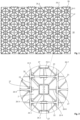
- the present invention relates to a device for producing a covering comprising a honeycomb structure, in particular in the form of a grid, serving as a template for producing a paving, in particular serving to embed/interlock paving stones.
- the invention is intended for a professional or an individual, and is intended in particular for applications of pedestrian crossing, vehicle rolling such as access roads to garages, pedestrian garden paths, public squares, sidewalks to name only these apps.
- the invention will in particular be applied to coatings from natural or reconstituted stone, solid or reconstituted wood, or concrete pavers, without however being limited thereto.
- Paving techniques are known, in particular techniques which consist in using solid self-supporting blocks such as paving stones reconstituted from concrete or solid paving stones, resulting from stone cutting.
- the pavers are laid one by one and it is necessary to ensure the flatness of the whole.
- the rolling surface is obtained with a very high resistance to wear, but using a very low thickness of material, thus reducing the price of the raw material, both in volume of material itself but also in transport.
- each cell of the structure comprises a foot to be in contact with the ground, and at least one communicating passage made in the lower part in each wall of a cell to ensure the passage of material from one cell to another and thus to link cells to each other.
- This clever structure nevertheless requires a cast material.
- the present invention therefore aims to provide yet another device for producing a floor covering, in particular applicable outdoors, which is of an affordable cost price, and which is easy and quick to produce in order to provide a covering surface under the shape of jointed cobblestones, while guaranteeing a rolling surface for vehicles that is durable and flat over time.
- the present invention therefore relates to a device for producing a floor covering as described in claim 1.
- the device for producing a floor covering comprises at least one honeycombed structure (grid) provided with a plurality of honeycombs which are each delimited by walls and an upper opening plane, and comprise each at least one foot and communication passages from one cell to the other, and is characterized in that each cell comprises a support intended to support a covering element (rigid in the form of a block) such as a paving stone or tile to be arranged in the cell.
- a covering element rigid in the form of a block
- the support makes it possible to arrange a block in the cell, and this without risk of the block sinking over time, in particular by the repeated passage of vehicles.
- Each covering element is removable relative to each cell.
- the covering element (paving stone, tile) is held in the cell by interlocking.
- the invention uses no bonding (tile adhesive type), no sealing of the covering elements (mortar type).
- no joint in particular of cement is to be made since the structure (via the walls of the cells) forms the joints of the lining, technically and aesthetically.
- the walls of each honeycomb structure form the seals of the covering, in particular the covering has no sealing material between the structure and the covering element.
- the structure of the invention avoids the prior production of a concrete slab or a bed of mortar.
- the honeycomb structure of the invention replaces a concrete slab.
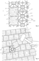
- the support comprises connecting elements which are integral with the walls and connected centrally to the cell.
- the support comprises a central zone, preferably forming a substantially square or rectangular resting surface (for a slab), and preferably elongated connecting elements also forming resting surfaces (for the slab) and connecting the zone central to the walls.
- cavities/passages are made under the connecting elements which thus form bridges to allow passage for any cables that have to run between the cells.
- the support forms a resting surface arranged at a depth relative to the upper opening plane of each cell which corresponds to the thickness of a block so that the block is coplanar or preferably projecting from report to said opening plan.
- the support of the covering element in the cell is at a distance from the upper plane of the opening of the cell and at an appropriate distance with respect to the thickness of the covering element so that said covering element is protruding above the structure (above the opening plane).
- Said covering element is intended to protrude (above) the structure, preferably by around 2 mm, so that walking or rolling is not on the structure/grid. Thus one cannot slide on the grid, the foot or the wheel not being in contact with the grid.
- the device comprises several adjacent honeycomb structures and at least one connecting piece for assembling two laterally abutting structures, preferably the connecting piece cooperating by interlocking or clipping.
- each structure to be butted comprises half-cells whose cutting plane divides a support in two providing a half-support, each structure being butted to the other by abutting two half-supports of two half-cells in vis-à-vis, the half-supports comprising means of mutual cooperation, such as female elements, with which the said at least one connecting piece cooperates by engagement.
- Each cell comprises retaining means, in particular the retaining means are arranged on the walls and comprise projecting shapes and/or chamfered surfaces from the plane of the upper opening towards the inside of the structure, so as to provide blocking by wedging of a block in position in the cell.
- the retaining means have a mechanical retaining function (without any bonding). It is thus quick and easy to associate the blocks by positioning them in the cells and by striking them, for example using a mallet.
- the pavers are embedded in the cells.
- the communication passages from one cell to another are arranged in the walls so as to allow the passage of electric cables and/or integrated garden hoses and/or to allow the passage of a tool from an open cell into an adjacent cell closed by a block in order to lift the associated block, in particular by leverage.
- the support forms at least one housing (a cavity) capable of receiving lighting means and/or connectors for a lighting pad.
- the support comes from the manufacture of the structure, preferably the structure is manufactured by molding plastic material, in particular based on polypropylene (PP) or polyurethane (PE) and resistant to wear and ultraviolet radiation.
- PP polypropylene
- PE polyurethane
- the device of the invention comprises a covering/pavement element per cell, the walls forming joints and providing at least one interstice with the pave (in particular a clearance of the order of the order of 1 mm) to ensure a drainage.
- the qualifiers “upper”, “lower”, of an element of the device are used within the framework of a normal installation of the device, that is to say relating to a vertical concept with respect to a ground on which the device would be placed.
- the coating production device 1 comprises one or more structures 10 intended to be placed on stabilized ground, the structure 10 comprising cells 2 which are intended to house paving stones 3, 3' by jamming.
- the material used for making the structure 10 is advantageously a plastic material, such as PP or PE, and preferably resistant to wear and to ultraviolet radiation.
- a structure 10 forms a plate advantageously made by molding in plastic material with a total thickness of the order of 4 cm.
- the plate can be easily cut to the desired contours to adapt to the surface profile to be coated.
- the structures can have various geometric shapes.
- Each cell 2 of structure 10 is delimited by walls 20 to 23 with at least one wall common to two cells.
- Each cell is open in the upper part but also in the lower part, said structure being intended to come directly into contact with the ground.
- Each cell has at least one foot 24, at least one passage 25 communicating from one cell to the other, at least one support 26 for carrying a block 3, retaining means 27 for the block, preferably the retaining means 27 providing at least one drainage gap 28 between at least one of the walls and a pavement.
- Each cell 2 comprises at least one foot 24, preferably several feet 24 over part of its periphery, such as in line with each wall intersection and each wall middle. These feet are in contact with the ground.
- Each of the cells 2 has at least one communicating passage 25, formed in each wall intended to serve as a common wall.
- the passages 25 are used to route electrical power cables through the structure when certain blocks 3' are provided to be illuminating and/or pipes for integrated watering.
- a passage 25 makes it possible, from a cell without a paving stone, to introduce a tool under the paving stone of the adjacent cell and to lever it up to lift said paving stone. Dismantling is thus greatly facilitated and very quick. This technique allows complete dismantling of the entire coating, which is impossible with the techniques of the prior art.
- the solution of the invention makes it possible to modify the direction of laying grids/structures, to modify a decorative pattern or to replace a stained paver, and this without any breakage or joint to (re)make.
- the dismantling of a first block is done by passing a thin tool blade at the level of a gap 28 between the block and one of the walls. Then, the dismantling continues via passages 25.
- the support 26 is intended to receive/support the weight of a block.
- the support 26 comprises a central support zone 26-1 and lateral zones 26-2 to 26-9 connecting the central zone 26-1 to the walls 20 to 23.
- the block 3 rests flat on the part top of all of these central 26-1 and lateral zones 26-2 to 26-9.
- the central zone 26-1 extends in area, for example in the form of a square or a rectangle, while the side zones 26-2 to 26-9 are elongated and, according to the invention, form rigid link arms.
- the lower part of the support 26, and therefore of the central and lateral zones, is intended to bear against the ground.
- the upper part of the support 26, and therefore the central and lateral zones, constitute a reception plane for a block 3, which is distant from the plane of the upper opening of the cell to correspond to the thickness of a block, for example of the order of 2 cm.
- the block/coating element is intended to protrude above the structure 10 (above the opening plane of each cell).
- the pavers protrude from the structure by about 2 mm.
- cavities are made under the connecting arms 26-2 to 26-9 which thus form bridges to allow passage for any cables that have to run between the cells.
- Each block 3 is held in a cell 2, on the support 26, by interlocking/wedging by cooperating with the retaining means 27.
- Each block 3 is placed in a cell 2 and is pushed in by tapping on it with a mallet.
- the walls 20 to 23 of the cells form the seals of the coating.
- the retaining means 27 are arranged in the upper part of the cell without protruding above the plane of the opening. They are arranged in a localized manner, for example centrally to each wall.
- the retaining means 27 form mechanical retaining means. There is interlocking of each paving stone, without the need for bonding means.
- the retaining means 27 form elements projecting from the vertical plane of a wall, such as spikes or ribs, and/or chamfers in each wall 20 to 23 with an inclination from the plane of the opening top of the cell towards the bottom and the center of said cell.
- a structure 2 presents its external edge for lateral abutment with another structure which passes through the median plane of the central zone 26-1 of several supports 26 ( figure 1 And 5 ); each structure has half-cells which are placed face-to-face to form cells in abutting manner.
- the assembly of two structures 2 is done by connecting pieces 4 which cooperate by mechanical insertion in female elements 29 provided in each central zone 26-1.
- the female elements 29 are for example at least two notches whose opening faces the upper opening of a cell, and are arranged facing each other with respect to the median assembly plane. Two notches 29 facing each other, which are respectively secured to two structures 2 abutting laterally, form a groove in which a slender connecting piece 4 is fitted.
- each central support zone 26-1 of a cell has four sides parallel to the respective walls 20 to 23 of a cell, and each side has a spaced pair of female elements/notches 29.
- the support 26 can constitute a housing/a cavity which makes it possible to accommodate the connectors of an illuminating or luminescent pad.
Claims (12)
- Vorrichtung (1) zum Herstellen einer Bodenflächenabdeckung, umfassend mindestens eine Zellenstruktur (10), die mit einer Vielzahl von Zellen (2) dotiert ist, die jeweils durch Wände (20, 21, 22, 23) und eine obere Öffnungsebene begrenzt sind und jeweils mindestens einen Fuß (24) und Kommunikationsdurchgänge (25) von einer Zelle zu der anderen umfassen, wobei jede Zelle (2) einen Träger (26) umfasst, der dazu bestimmt ist, ein Abdeckungselement (3) zu tragen, wie ein Pflasterstein oder eine Fliese, das in der Zelle anzuordnen ist, dadurch gekennzeichnet, dass der Träger (26) einen zentralen Bereich (26-1), der in der Zelle zentral ist, sowie Verbindungselemente (26-2 bis 26-9) umfasst, die den zentralen Bereich mit den Wänden in Form von starren Verbindungsarmen verbinden, und dass unter den Verbindungselementen (26-2 bis 26-9) Hohlräume ausgebildet sind, die Brücken bilden.
- Vorrichtung nach Anspruch 1, dadurch gekennzeichnet, dass der zentrale Bereich (26-1) des Trägers im Wesentlichen quadratisch oder rechteckig ist und die Verbindungselemente (26-2 bis 26-9) länglich sind.
- Vorrichtung nach Anspruch 1 oder 2, dadurch gekennzeichnet, dass der Träger (26) eine Auflageoberfläche bildet, die in einer Tiefe in Bezug auf die obere Öffnungsebene jeder Zelle (2) angeordnet ist, die der Dicke eines Pflastersteins entspricht, der von dem Träger getragen werden soll, so dass der Pflasterstein koplanar ist oder vorzugsweise in Bezug auf die Öffnungsebene hervorsteht.
- Vorrichtung nach einem der vorstehenden Ansprüche,
dadurch gekennzeichnet, dass sie mehrere benachbarte Zellenstrukturen (10) und mindestens ein Verbindungsstück (4) zum Zusammenfügen von zwei seitlich aneinanderstoßenden Strukturen umfasst, wobei das Verbindungsstück vorzugsweise durch Einpassen oder Einrasten zusammenwirkt. - Vorrichtung nach dem vorstehenden Anspruch,
dadurch gekennzeichnet, dass jede Struktur (10) Halbzellen umfasst, deren Schnittebene einen Träger in zwei Hälften teilt, wodurch ein Halbträger entsteht, wobei jede Struktur an die andere anstößt, indem zwei Halbträger von zwei gegenüberliegenden Halbzellen in Anschlag gebracht werden, wobei die Halbträger Mittel zum gegenseitigen Zusammenwirken umfassen, wie zum Beispiel Aufnahmeelemente (29), mit denen das mindestens eine Verbindungsstück durch Eingriff zusammenwirkt. - Vorrichtung nach einem der vorstehenden Ansprüche,
dadurch gekennzeichnet, dass die Kommunikationsdurchgänge (25) von einer Zelle zu der anderen in den Wänden so angeordnet sind, dass sie den Durchgang von elektrischen Kabeln und/oder integrierten Bewässerungsschläuchen ermöglichen und/oder den Durchgang eines Werkzeugs von einer offenen Zelle in eine benachbarte, durch einen Pflasterstein verschlossene Zelle ermöglichen, um den zugehörigen Pflasterstein zu heben, insbesondere durch Hebelwirkung. - Vorrichtung nach einem der vorstehenden Ansprüche,
dadurch gekennzeichnet, dass jede Zelle Haltemittel (27) umfasst, wobei insbesondere die Haltemittel an den Wänden angeordnet sind und vorspringende Formen und/oder abgeschrägte Oberflächen von der Ebene der oberen Öffnung in Richtung des Inneren der Struktur umfassen. - Vorrichtung nach einem der vorstehenden Ansprüche,
dadurch gekennzeichnet, dass der Träger (26) mindestens eine Einlassung bildet, die geeignet ist, Beleuchtungsmittel und/oder Anschlusstechnik aufzunehmen. - Vorrichtung nach einem der vorstehenden Ansprüche,
dadurch gekennzeichnet, dass der Träger aus der Erzeugung der Struktur stammt, wobei vorzugsweise die Struktur durch Formen von Kunststoffmaterial, insbesondere auf der Basis von Polypropylen (PP) oder Polyurethan (PE), erzeugt wird. - Vorrichtung nach einem der vorstehenden Ansprüche,
dadurch gekennzeichnet, dass sie ein Abdeckungselement pro Zelle umfasst, wobei die Wände Dichtungen bilden und mindestens ein Zwischenraum (28) vorgesehen ist, um eine Drainage zu gewährleisten. - Bodenflächenabdeckung, wie zum Beispiel eine Platte, ein Pflasterstein oder eine Fliese, die einer Vorrichtung nach einem der vorstehenden Ansprüche umfasst, wobei jede Zelle ein Abdeckungselement, wie zum Beispiel eine Platte, einen Pflasterstein oder eine Fliese, umfasst, das durch Einpassen eingesetzt wird.
- Bodenflächenabdeckung nach dem vorstehenden Anspruch,
dadurch gekennzeichnet, dass die Wände jeder Zellenstruktur die Dichtungen der Abdeckung bilden, wobei insbesondere die Abdeckung frei von Versiegelungsmaterial zwischen der Struktur und dem Abdeckungselement ist.
Applications Claiming Priority (2)
| Application Number | Priority Date | Filing Date | Title |
|---|---|---|---|
| FR1859335A FR3086955B1 (fr) | 2018-10-09 | 2018-10-09 | Dispositif de realisation d'un revetement par encastrement de paves |
| PCT/EP2019/077377 WO2020074589A1 (fr) | 2018-10-09 | 2019-10-09 | Dispositif de réalisation d'un revêtement de sol par encastrement de pavés |
Publications (3)
| Publication Number | Publication Date |
|---|---|
| EP3864221A1 EP3864221A1 (de) | 2021-08-18 |
| EP3864221C0 EP3864221C0 (de) | 2023-08-23 |
| EP3864221B1 true EP3864221B1 (de) | 2023-08-23 |
Family
ID=65494336
Family Applications (1)
| Application Number | Title | Priority Date | Filing Date |
|---|---|---|---|
| EP19797174.0A Active EP3864221B1 (de) | 2018-10-09 | 2019-10-09 | Vorrichtung zur herstellung einer bodenflächenabdeckung durch einbettung von pflastersteinen |
Country Status (4)
| Country | Link |
|---|---|
| EP (1) | EP3864221B1 (de) |
| ES (1) | ES2965841T3 (de) |
| FR (1) | FR3086955B1 (de) |
| WO (1) | WO2020074589A1 (de) |
Family Cites Families (7)
| Publication number | Priority date | Publication date | Assignee | Title |
|---|---|---|---|---|
| US3504472A (en) * | 1967-09-12 | 1970-04-07 | Andrew B Clement | Portable patio floor structure |
| US4047825A (en) * | 1976-06-14 | 1977-09-13 | The Raymond Lee Organization, Inc. | Rollable walk guide |
| KR100834516B1 (ko) * | 2007-07-02 | 2008-06-02 | 박재민 | 연성을 갖는 보도블록 |
| KR20070078835A (ko) * | 2007-07-12 | 2007-08-02 | 김진완 | 조립식 포장재 블록 세트 |
| KR200449175Y1 (ko) * | 2007-12-26 | 2010-06-22 | 김진완 | 체스블럭용 격자틀 및 이를 구비한 보도블럭 세트 |
| KR101231177B1 (ko) * | 2011-03-30 | 2013-02-07 | 최강진 | 투수성 보도블록 침하방지 구조 |
| FR2989699B1 (fr) | 2012-04-23 | 2015-09-11 | Christophe Desire | Procede de realisation de revetement de sol in situ et dispositif associe |
-
2018
- 2018-10-09 FR FR1859335A patent/FR3086955B1/fr active Active
-
2019
- 2019-10-09 ES ES19797174T patent/ES2965841T3/es active Active
- 2019-10-09 EP EP19797174.0A patent/EP3864221B1/de active Active
- 2019-10-09 WO PCT/EP2019/077377 patent/WO2020074589A1/fr unknown
Also Published As
| Publication number | Publication date |
|---|---|
| EP3864221A1 (de) | 2021-08-18 |
| EP3864221C0 (de) | 2023-08-23 |
| ES2965841T3 (es) | 2024-04-17 |
| FR3086955A1 (fr) | 2020-04-10 |
| WO2020074589A1 (fr) | 2020-04-16 |
| FR3086955B1 (fr) | 2021-12-17 |
Similar Documents
| Publication | Publication Date | Title |
|---|---|---|
| FR2781513A1 (fr) | Element de surface du genre dalle, panneau pour sol, mur, toiture par exemple | |
| EP0122210B1 (de) | Glaselement, insbesondere Ziegel- oder Pflasterstein | |
| EP3864221B1 (de) | Vorrichtung zur herstellung einer bodenflächenabdeckung durch einbettung von pflastersteinen | |
| CA2443804C (fr) | Ensemble d'elements de construction | |
| EP1470302A1 (de) | Modulares fussbodensystem mit rahmenfliesen | |
| EP0814218B1 (de) | Homogene modulare Verbundelemente, zum Herstellen von Wand- oder Bodenbekleidungen | |
| FR3082544A1 (fr) | Dispositif pour un plot de terrasse, plot comprenant un tel dispositif et installation de terrasse sur plots comprenant des elements de planchers supportes par de tels plots | |
| EP3006646B1 (de) | Verkleidungssystem vom typ platten auf stelzlagern, das mindestens einen behälter umfasst | |
| FR2952661A1 (fr) | Voutain avec languette de finition | |
| EP1211355A1 (de) | Unterbaumauer für eine Konstruktion und Verwirklichungsverfahren | |
| FR3053710A1 (fr) | Dalle composite et systeme de revetement comprenant de telles dalles | |
| FR2515232A1 (fr) | Element de construction tel que brique, plaque, pave ou analogue | |
| FR2989699A1 (fr) | Procede de realisation de revetement de sol in situ et dispositif associe | |
| EP2115348B1 (de) | Beleuchtungsvorrichtung, im besonderen zur signalisierung, dekoration und beleuchtung | |
| FR2570116A1 (fr) | Dallage a joints minces en pierre ou marbre | |
| FR3094996A1 (fr) | Soubassement de clôture et structure de clôture comprenant un tel soubassement | |
| FR2923507A1 (fr) | Bloc de construction a proprietes thermiques ameliorees | |
| FR2956135A1 (fr) | Dispositif d'isolation pour plancher a poutrelles | |
| FR2989984A1 (fr) | Dalle pour revetement de sol, et revetement de sol forme de telles dalles assemblees | |
| EP0218537B1 (de) | Verbundpflasterstein | |
| EP2148019A2 (de) | Blockbaustein für Mauern | |
| FR3033812A1 (fr) | Bordure rectiligne d'element de construction et element de construction comportant une telle bordure. | |
| FR2639374A1 (fr) | Dalle pour revetements de sol | |
| FR2607529A1 (fr) | Dispositif pour la realisation de pavage et son procede de mise en oeuvre | |
| FR3088664A1 (fr) | Dalle composite et système de revêtement comprenant de telles dalles |
Legal Events
| Date | Code | Title | Description |
|---|---|---|---|
| STAA | Information on the status of an ep patent application or granted ep patent |
Free format text: STATUS: UNKNOWN |
|
| STAA | Information on the status of an ep patent application or granted ep patent |
Free format text: STATUS: THE INTERNATIONAL PUBLICATION HAS BEEN MADE |
|
| PUAI | Public reference made under article 153(3) epc to a published international application that has entered the european phase |
Free format text: ORIGINAL CODE: 0009012 |
|
| STAA | Information on the status of an ep patent application or granted ep patent |
Free format text: STATUS: REQUEST FOR EXAMINATION WAS MADE |
|
| 17P | Request for examination filed |
Effective date: 20210409 |
|
| AK | Designated contracting states |
Kind code of ref document: A1 Designated state(s): AL AT BE BG CH CY CZ DE DK EE ES FI FR GB GR HR HU IE IS IT LI LT LU LV MC MK MT NL NO PL PT RO RS SE SI SK SM TR |
|
| DAV | Request for validation of the european patent (deleted) | ||
| DAX | Request for extension of the european patent (deleted) | ||
| GRAP | Despatch of communication of intention to grant a patent |
Free format text: ORIGINAL CODE: EPIDOSNIGR1 |
|
| STAA | Information on the status of an ep patent application or granted ep patent |
Free format text: STATUS: GRANT OF PATENT IS INTENDED |
|
| INTG | Intention to grant announced |
Effective date: 20230313 |
|
| GRAS | Grant fee paid |
Free format text: ORIGINAL CODE: EPIDOSNIGR3 |
|
| GRAA | (expected) grant |
Free format text: ORIGINAL CODE: 0009210 |
|
| STAA | Information on the status of an ep patent application or granted ep patent |
Free format text: STATUS: THE PATENT HAS BEEN GRANTED |
|
| AK | Designated contracting states |
Kind code of ref document: B1 Designated state(s): AL AT BE BG CH CY CZ DE DK EE ES FI FR GB GR HR HU IE IS IT LI LT LU LV MC MK MT NL NO PL PT RO RS SE SI SK SM TR |
|
| REG | Reference to a national code |
Ref country code: GB Ref legal event code: FG4D Free format text: NOT ENGLISH |
|
| REG | Reference to a national code |
Ref country code: CH Ref legal event code: EP |
|
| REG | Reference to a national code |
Ref country code: DE Ref legal event code: R096 Ref document number: 602019035736 Country of ref document: DE |
|
| REG | Reference to a national code |
Ref country code: IE Ref legal event code: FG4D Free format text: LANGUAGE OF EP DOCUMENT: FRENCH |
|
| U01 | Request for unitary effect filed |
Effective date: 20230921 |
|
| U07 | Unitary effect registered |
Designated state(s): AT BE BG DE DK EE FI FR IT LT LU LV MT NL PT SE SI Effective date: 20230928 |
|
| U20 | Renewal fee paid [unitary effect] |
Year of fee payment: 5 Effective date: 20231027 |
|
| PG25 | Lapsed in a contracting state [announced via postgrant information from national office to epo] |
Ref country code: IS Free format text: LAPSE BECAUSE OF FAILURE TO SUBMIT A TRANSLATION OF THE DESCRIPTION OR TO PAY THE FEE WITHIN THE PRESCRIBED TIME-LIMIT Effective date: 20231223 |
|
| REG | Reference to a national code |
Ref country code: GR Ref legal event code: EP Ref document number: 20230402272 Country of ref document: GR Effective date: 20240110 |
|
| PG25 | Lapsed in a contracting state [announced via postgrant information from national office to epo] |
Ref country code: RS Free format text: LAPSE BECAUSE OF FAILURE TO SUBMIT A TRANSLATION OF THE DESCRIPTION OR TO PAY THE FEE WITHIN THE PRESCRIBED TIME-LIMIT Effective date: 20230823 Ref country code: NO Free format text: LAPSE BECAUSE OF FAILURE TO SUBMIT A TRANSLATION OF THE DESCRIPTION OR TO PAY THE FEE WITHIN THE PRESCRIBED TIME-LIMIT Effective date: 20231123 Ref country code: IS Free format text: LAPSE BECAUSE OF FAILURE TO SUBMIT A TRANSLATION OF THE DESCRIPTION OR TO PAY THE FEE WITHIN THE PRESCRIBED TIME-LIMIT Effective date: 20231223 Ref country code: HR Free format text: LAPSE BECAUSE OF FAILURE TO SUBMIT A TRANSLATION OF THE DESCRIPTION OR TO PAY THE FEE WITHIN THE PRESCRIBED TIME-LIMIT Effective date: 20230823 |
|
| PG25 | Lapsed in a contracting state [announced via postgrant information from national office to epo] |
Ref country code: PL Free format text: LAPSE BECAUSE OF FAILURE TO SUBMIT A TRANSLATION OF THE DESCRIPTION OR TO PAY THE FEE WITHIN THE PRESCRIBED TIME-LIMIT Effective date: 20230823 |
|
| PGFP | Annual fee paid to national office [announced via postgrant information from national office to epo] |
Ref country code: GR Payment date: 20240109 Year of fee payment: 5 |
|
| PGFP | Annual fee paid to national office [announced via postgrant information from national office to epo] |
Ref country code: ES Payment date: 20240109 Year of fee payment: 5 |
|
| REG | Reference to a national code |
Ref country code: ES Ref legal event code: FG2A Ref document number: 2965841 Country of ref document: ES Kind code of ref document: T3 Effective date: 20240417 |
|
| PG25 | Lapsed in a contracting state [announced via postgrant information from national office to epo] |
Ref country code: SM Free format text: LAPSE BECAUSE OF FAILURE TO SUBMIT A TRANSLATION OF THE DESCRIPTION OR TO PAY THE FEE WITHIN THE PRESCRIBED TIME-LIMIT Effective date: 20230823 Ref country code: RO Free format text: LAPSE BECAUSE OF FAILURE TO SUBMIT A TRANSLATION OF THE DESCRIPTION OR TO PAY THE FEE WITHIN THE PRESCRIBED TIME-LIMIT Effective date: 20230823 Ref country code: CZ Free format text: LAPSE BECAUSE OF FAILURE TO SUBMIT A TRANSLATION OF THE DESCRIPTION OR TO PAY THE FEE WITHIN THE PRESCRIBED TIME-LIMIT Effective date: 20230823 Ref country code: SK Free format text: LAPSE BECAUSE OF FAILURE TO SUBMIT A TRANSLATION OF THE DESCRIPTION OR TO PAY THE FEE WITHIN THE PRESCRIBED TIME-LIMIT Effective date: 20230823 |
|
| PGFP | Annual fee paid to national office [announced via postgrant information from national office to epo] |
Ref country code: CH Payment date: 20240110 Year of fee payment: 5 Ref country code: GB Payment date: 20240109 Year of fee payment: 5 |