EP3863232B1 - Mit zwei verschiedenen versorgungsspannungsdomänen verbundener monolithischer hochspannungs-sendeempfänger - Google Patents
Mit zwei verschiedenen versorgungsspannungsdomänen verbundener monolithischer hochspannungs-sendeempfänger Download PDFInfo
- Publication number
- EP3863232B1 EP3863232B1 EP20155913.5A EP20155913A EP3863232B1 EP 3863232 B1 EP3863232 B1 EP 3863232B1 EP 20155913 A EP20155913 A EP 20155913A EP 3863232 B1 EP3863232 B1 EP 3863232B1
- Authority
- EP
- European Patent Office
- Prior art keywords
- supply voltage
- domain
- interface
- voltage
- differential
- Prior art date
- Legal status (The legal status is an assumption and is not a legal conclusion. Google has not performed a legal analysis and makes no representation as to the accuracy of the status listed.)
- Active
Links
Images

Classifications
-
- H—ELECTRICITY
- H04—ELECTRIC COMMUNICATION TECHNIQUE
- H04L—TRANSMISSION OF DIGITAL INFORMATION, e.g. TELEGRAPHIC COMMUNICATION
- H04L12/00—Data switching networks
- H04L12/28—Data switching networks characterised by path configuration, e.g. LAN [Local Area Networks] or WAN [Wide Area Networks]
- H04L12/40—Bus networks
- H04L12/40006—Architecture of a communication node
- H04L12/40013—Details regarding a bus controller
-
- H—ELECTRICITY
- H04—ELECTRIC COMMUNICATION TECHNIQUE
- H04L—TRANSMISSION OF DIGITAL INFORMATION, e.g. TELEGRAPHIC COMMUNICATION
- H04L12/00—Data switching networks
- H04L12/28—Data switching networks characterised by path configuration, e.g. LAN [Local Area Networks] or WAN [Wide Area Networks]
- H04L12/40—Bus networks
- H04L12/40006—Architecture of a communication node
- H04L12/40045—Details regarding the feeding of energy to the node from the bus
-
- H—ELECTRICITY
- H03—ELECTRONIC CIRCUITRY
- H03K—PULSE TECHNIQUE
- H03K19/00—Logic circuits, i.e. having at least two inputs acting on one output; Inverting circuits
- H03K19/0175—Coupling arrangements; Interface arrangements
- H03K19/0185—Coupling arrangements; Interface arrangements using field effect transistors only
- H03K19/018507—Interface arrangements
-
- B—PERFORMING OPERATIONS; TRANSPORTING
- B60—VEHICLES IN GENERAL
- B60R—VEHICLES, VEHICLE FITTINGS, OR VEHICLE PARTS, NOT OTHERWISE PROVIDED FOR
- B60R16/00—Electric or fluid circuits specially adapted for vehicles and not otherwise provided for; Arrangement of elements of electric or fluid circuits specially adapted for vehicles and not otherwise provided for
- B60R16/02—Electric or fluid circuits specially adapted for vehicles and not otherwise provided for; Arrangement of elements of electric or fluid circuits specially adapted for vehicles and not otherwise provided for electric constitutive elements
-
- H—ELECTRICITY
- H04—ELECTRIC COMMUNICATION TECHNIQUE
- H04L—TRANSMISSION OF DIGITAL INFORMATION, e.g. TELEGRAPHIC COMMUNICATION
- H04L12/00—Data switching networks
- H04L12/28—Data switching networks characterised by path configuration, e.g. LAN [Local Area Networks] or WAN [Wide Area Networks]
- H04L12/40—Bus networks
- H04L12/40169—Flexible bus arrangements
-
- H—ELECTRICITY
- H04—ELECTRIC COMMUNICATION TECHNIQUE
- H04L—TRANSMISSION OF DIGITAL INFORMATION, e.g. TELEGRAPHIC COMMUNICATION
- H04L12/00—Data switching networks
- H04L12/28—Data switching networks characterised by path configuration, e.g. LAN [Local Area Networks] or WAN [Wide Area Networks]
- H04L12/40—Bus networks
- H04L2012/40208—Bus networks characterized by the use of a particular bus standard
- H04L2012/40215—Controller Area Network CAN
-
- H—ELECTRICITY
- H04—ELECTRIC COMMUNICATION TECHNIQUE
- H04L—TRANSMISSION OF DIGITAL INFORMATION, e.g. TELEGRAPHIC COMMUNICATION
- H04L12/00—Data switching networks
- H04L12/28—Data switching networks characterised by path configuration, e.g. LAN [Local Area Networks] or WAN [Wide Area Networks]
- H04L12/40—Bus networks
- H04L2012/40208—Bus networks characterized by the use of a particular bus standard
- H04L2012/40241—Flexray
-
- H—ELECTRICITY
- H04—ELECTRIC COMMUNICATION TECHNIQUE
- H04L—TRANSMISSION OF DIGITAL INFORMATION, e.g. TELEGRAPHIC COMMUNICATION
- H04L12/00—Data switching networks
- H04L12/28—Data switching networks characterised by path configuration, e.g. LAN [Local Area Networks] or WAN [Wide Area Networks]
- H04L12/40—Bus networks
- H04L2012/40267—Bus for use in transportation systems
- H04L2012/40273—Bus for use in transportation systems the transportation system being a vehicle
Definitions
- the invention relates to a transceiver device for interfacing between at least two different voltage domains, and to a method of interfacing between at least two different voltage domains.
- MHEVs Mild Electric Hybrid Vehicles
- 12V or 24V on the one hand
- 48V on the other hand
- an electric motor such as e.g. an electric starter generator
- the electric high-power applications including an electric motor, such as e.g. an electric starter generator, of the vehicle, which are typically operative in the range of 1 to 15 kW, are connected to the 48V board net.
- the Controller Area Network (CAN) bus is often used in automotive and industrial automation applications.
- the CAN bus system was developed in 1983 by the company Bosch and presented publically in 1986 together with the company Intel.
- the CAN bus has evolved to a bus standard in automotive and industrial automation applications, and is described in ISO 11898.
- a CAN bus can support bit-rates up to 8 Mbps in the case of the extension CAN FD, which was developed in 2011 and released in 2012 by the company Bosch, if the network topology is correctly terminated.
- ECUs operating at 48V typically have four power connector pins:
- a 48V CAN transceiver is typically connected between the 12V/24V voltage supply domain and the 48V voltage supply domain, as is illustrated in Fig. 1 and as is described further below.
- CAN transceivers with high-voltage galvanic isolation are used to handle with, or connect to, both board net domains.
- galvanic isolation barrier the following methods are used: (voltage) transformer, capacitor, or optocoupler. All these known galvanic isolation barriers are expensive solutions, because such CAN transceivers consist of multiple integrated circuit dies in one package (multi-chip module package). Or even worse, a discrete solution comprising a separate CAN transceiver device and one or more separate galvanic isolation devices may be applied.
- CAN networks which have been developed in the automotive industry in respect of MHEVs, and the present invention - as will be disclosed in the following - has been developed initially in this field of technology
- the present invention can be generalized to be applicable in interfacing to other bus systems, such as a Local Interconnect Network (LIN) bus (as described in ISO 17987) and a FlexRay bus (as described in ISO 17458-1 to 17458-5), or more generally to a communication medium, including e.g. Ethernet, in interfacing between supply voltage domains different having different supply voltages than 12/24V and 48V (as used in the automotive industry).
- LIN Local Interconnect Network
- FlexRay bus as described in ISO 17458-1 to 17458-5
- a communication medium including e.g. Ethernet
- US 2015/029626 A1 relates to an electronic device comprising a control module, a transceiver module, a first isolator and a second isolator, wherein the control module is configured to generate a control signal in response to a signal from an MCU.
- US 10,498,396 B1 relates to the field of transceiver devices wherein galvanic isolation is provided between different semiconductor regions.
- the present invention relates to a transceiver device for interfacing between at least two different voltage domains, and to a method of interfacing between at least two different voltage domains.
- Further objects of the present invention comprise a provision of common mode tolerance, and measures against high voltages and currents crossing from one domain to the other.
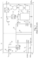
- Fig. 1 shows a schematic block diagram of an electrical network system, e.g. an electronic control unit (ECU), 10 having a first supply voltage domain 12, a second supply voltage domain 14, and a transceiver device 96, which has a galvanic isolation barrier 98 in a conventional manner, for interfacing between the first and the second supply voltage domain 12, 14.
- ECU electronice control unit
- the electrical network system 10 is a mixed 12V/48V or 24V/48V CAN network in a MHEV (not shown), the transceiver device 96 is a 48V CAN transceiver of the MHEV, the first supply voltage is substantially nominal 48V and the second supply voltage is substantially nominal 12V or 24V in the MHEV.
- the 48V CAN transceiver 96 has, in a conventional manner, a galvanic isolation barrier 98, which may be embodied according to one of the following methods: (voltage) transformer, capacitor, or optocoupler.
- the first supply voltage domain (or high-voltage supply domain) 12 is supplied by a first (or high) supply voltage via a pair of pins 54, 56, viz. a high-voltage/first domain supply 54 (e.g. nominal 48V car board net supply, often referred to as V BN48 ) and a high-voltage/first domain ground (e.g. ground connector of 48V car board net, often referred to as GND 48 ).
- a high-voltage/first domain supply 54 e.g. nominal 48V car board net supply, often referred to as V BN48
- a high-voltage/first domain ground e.g. ground connector of 48V car board net, often referred to as GND 48 .
- the second supply voltage domain (or low-voltage supply domain) 14 is supplied by a second (or low) supply voltage via a pair of pins 72, 74, viz. a low-voltage/second domain supply 72 (e.g. nominal 12V or 24V car board net supply, often referred to as V BN12/24 ) and a low-voltage/second domain ground 74 (e.g. ground connector of 12V or 24V car board net / GND 12/24 ).
- a low-voltage/second domain supply 72 e.g. nominal 12V or 24V car board net supply, often referred to as V BN12/24
- a low-voltage/second domain ground 74 e.g. ground connector of 12V or 24V car board net / GND 12/24 .
- the electrical network system 10 of the MHEV comprises, in the first (high) supply voltage domain 12, an electric motor, such as e.g. an electric starter generator, 50, a first voltage converter 52 (viz. 48V/12V), a second voltage converter (viz. 12V/VDD1), a microcontroller unit 32 for controlling among others the operation of the electric motor 50 via a driving line comprising a gate driver unit (GDU) 42, a power stage 46 for driving the electric motor 50, and the electric motor 50.
- GDU gate driver unit
- a 48V input of the a first voltage converter 52 is connected to the a high-voltage/first domain supply 54 (V BN48 ).
- a 12V output of the first voltage converter 52 is connected to a first connection point 59, which is also connected to a 12V input of the second voltage converter 60.
- a VDD1 (for example, 5V) output of the second voltage converter 60 is connected to a voltage supply input of the microcontroller 32.
- the microcontroller 32 outputs, among others, control signals via a first control signal line 40 to a control input of the GDU 42.
- the GDU 42 outputs, control signals via a second control signal line 44 to a control input of the power stage 46.
- the power stage 46 outputs via a drive signal line 48 high-power driving voltages and driving currents for driving the electric motor 50 of the MHEV.
- the second supply voltage domain (or low-voltage supply domain) 14 is supplied by a second (or low) supply voltage via a pair of pins 72, 74, viz. a low-voltage/second domain supply 72 (e.g. nominal 12V or 24V car board net supply, often referred to as V BN12/24 ) and a low-voltage/second domain ground 74 (e.g. ground connector of 12V or 24V car board net / GND 12/24 ).
- a low-voltage/second domain supply 72 e.g. nominal 12V or 24V car board net supply, often referred to as V BN12/24
- a low-voltage/second domain ground 74 e.g. ground connector of 12V or 24V car board net / GND 12/24 .
- the electrical network system 10 of the MHEV comprises, in the second (low) supply voltage domain 14, a CAN bus 24, which comprises a CAN bus high line 26 and a CAN bus low line 28, for connecting to various ECUs and devices connected to the second (low) supply voltage domain 14.
- a CAN bus 24 which comprises a CAN bus high line 26 and a CAN bus low line 28, for connecting to various ECUs and devices connected to the second (low) supply voltage domain 14.
- the transceiver device 96 which is embodied in Fig. 1 as a conventional 48V CAN transceiver, as such, comprises in the first (high) voltage domain 12 the following pins:VDD1, TXD, RXD, and GND48. Furthermore, the conventional 48V CAN transceiver, as such comprises in the second (low) voltage domain 14 the following pins: VDD2, CANH, CANL, and GND12. These pins are similar in function, and correspond to the pins of the 48V CAN transceiver shown in Fig. 2 , which exemplifies a transceiver device 100 according to the invention, and which is described further below with reference to Fig. 2 .
- the conventional 48V CAN transceiver 96 has a galvanic isolation between the pins in the first (high) voltage domain 12 and the pins in the second (low) voltage domain 14.
- the galvanic isolation barrier may be implemented to comprise one of a galvanic isolation transformer, a galvanic isolation capacitor, or a galvanic isolation optocoupler.
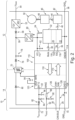
- Fig. 2 shows a schematic block diagram of an electrical network system, e.g. an electronic control unit (ECU), 10 according to the present invention, wherein the electrical network system 10 has a first supply voltage domain 12, a second supply voltage domain 14, and a transceiver device 100 according to the present invention for interfacing between the first and the second supply voltage domain 12, 14.
- ECU electronice control unit
- the electrical network system 10 shown in Fig. 2 corresponds to the electrical network system 10 shown in Fig. 1 , with a first exception that the conventional transceiver device 96, which is embodied as a 48V CAN transceiver in Fig. 1 , is replaced by a transceiver device 100 according to the invention, which is embodied in Fig. 2 likewise as a 48V CAN transceiver, and however according to the invention, and a second exception that the transceiver device 100 has some additional functional pins both in the first and the second supply voltage domain, a third exception that the electrical network system 10 has some additional elements that are described below.
- the transceiver device 100 has a first interface 110, a second interface 120, a first internal communication link 130 and a second internal communication link 170, wherein the internal communication links 130 and 170 bridge between the first and the second interface 110, 120.
- first and second internal communication links may be more than one first and second internal communication links, for example, a further first and second internal communication link for transmitting a mode signal (or a device mode indicating signal), for example from the second voltage supply domain to the first voltage supply domain, a still further first and second internal communication link for transmitting a wake signal, for example from the first voltage supply domain to the second voltage supply domain, and a still further first and second internal communication link for transmitting a device status information signal.
- a mode signal or a device mode indicating signal
- a wake signal for example from the first voltage supply domain to the second voltage supply domain
- a still further first and second internal communication link for transmitting a device status information signal.
- the first (high) supply voltage domain 12 and the second (low) supply voltage domain 14 are interfaced, independently and outside of the transceiver device 100, by a galvanic isolated flyback converter 70.
- a second (low) supply voltage terminal of the galvanic isolated flyback converter 70 is supplied by (or connected to) the low-voltage/second domain supply 72 via a fourth diode 80.
- a first (high) supply voltage terminal of the galvanic isolated flyback converter 70 connects via a second diode 76 to the first connection point 59, and hence to the 12V input of the second voltage converter 60.
- the first connection point 59 is buffered to high-voltage/first domain ground 56 via a third capacitor 78.
- the transceiver device 100 is for interfacing between at least two different voltage domains 12 and 14, which comprise namely the first supply voltage domain 12, which has a higher first supply voltage, and the second supply voltage domain 14, which has a lower second supply voltage.
- the transceiver device 100 has a first interface 110, which is supplied by the first supply voltage and is adapted to interface to at least one external first digital device 20 operating in the first supply voltage domain 12; and a second interface 120, which is supplied by the second supply voltage and is adapted to interface to an external communication bus 24 operating in the second supply voltage domain 14.
- the transceiver device 100 further has a first internal communication link 130, which is adapted to transfer transmit data, which are generatable by the external first digital device 20 operating in the first supply voltage domain 12, from the first interface 110 to the second interface 120; and a second internal communication link 170, which is adapted to transfer receive data, which may be supplied from the external communication bus 24 operating in the second supply voltage domain 14, from the second interface 120 to the first interface 110.
- the receive data may originate from a device that operates in the second supply voltage domain 14 and is connected to the communication bus 24.
- the first and the second internal communication links 130 and 170 together enable bidirectional transmission of transmit data and receive data between a digital device 30, for example the microcontroller unit (MCU) 32, operating in the first (high) supply voltage domain 12 and the communication bus 24, for example a CAN bus, operating in the second (low) supply voltage domain 14.
- a digital device for example the microcontroller unit (MCU) 32, operating in the first (high) supply voltage domain 12 and the communication bus 24, for example a CAN bus, operating in the second (low) supply voltage domain 14.
- MCU microcontroller unit
- the internal communication links 130, 170 are tolerant to ground offsets, common mode transients between the first supply voltage domain 12 (which may be embodied as the 12V/24V domain of the MHEV) and the second supply voltage domain 14 (which may be embodied as the 48V domain of the MHEV), and minimizes reverse currents into the CAN bus lines in loss of ground scenarios.
- the transceiver device 100 does not have nor needs a galvanic isolation barrier (see e.g. 98 in Fig. 1 ), for which one of the following methods are conventionally known: transformer, capacitor, or optocoupler. All these galvanic isolation barriers are expensive solutions, because according transceiver devices 96, e.g. CAN transceivers, as shown in Fig. 1 , consist of multiple integrated circuit dies in one package (multi-chip module package), or even worse and more expensive separate devices out of a transceiver device and one or more galvanic isolation devices may have to be applied.
- the transceiver device 100 has the first and second internal communication link 130 and 170, and may have more than one first and second internal communication links as mentioned above. As such, i.e. with all these components, the transceiver device 100 can be embodied as a monolithic integrated circuit.
- the monolithic integrated circuit including in particular the first and second internal communication links 130 and 170, can be implemented in silicon-on-insulator (SOI) technology, in particular high-voltage SOI technology.
- SOI silicon-on-insulator
- the transceiver device 100 has at least two ground pins 114, 124, which include a ground pin of the first supply voltage (or first domain ground, GND 48 ) 114 that is adapted to be connected to a ground potential 56 of the first voltage supply domain 12, and a ground pin of the second supply voltage (or second domain ground, GND 12/24 ) 124 that is adapted to be connected to a ground potential 74 of the second voltage supply domain 14.
- the transceiver device 100 may have a common mode and ground offset range from approximately ⁇ 3V to approximately ⁇ 70V.
- the first supply voltage may be substantially nominal 48V or greater.
- the second supply voltage may be substantially nominal 12V or substantially nominal 24V. This enables the transceiver device 100 to be applicable in automotive applications, e.g. in Mild Electric Hybrid Vehicles (MEHV).
- MEHV Mild Electric Hybrid Vehicles
- the first interface 110 has a transmit data input 116 adapted to receive the transmit data, e.g. from the first digital device 20 operating in the first supply voltage domain 12, and a receive data output 118 adapted to transmit the receive data, e.g. to a second digital device 22 operating in the first supply voltage domain 12.
- the first and the second digital devices 20 and 22 operating in the first supply voltage domain 12 may be a same digital device 30.
- the first and the second digital devices 20 and 22 operating in the first supply voltage domain 12 together may form a microcontroller unit 32.
- the second interface 120 has a CAN high pin 126 and a CAN low pin 128, which together are adapted to transmit the transmit data to and/or to receive the receive data from the CAN bus as the external communication bus 24 operating in the second supply voltage domain 14.
- the communication bus 24 may be selected from the group consisting of a CAN bus, a Flexray bus, a LIN bus, and an Ethernet.
- the first and the second internal communication link 130 and 170 are based on differential voltage transmission, as will be explained further below with reference to Fig. 4 .
- the first and the second internal communication link 130 and 170 may be based on digital current loop transmission, as will be explained further below with reference to Figs. 5 and 6 .
- the transceiver device 100 may be embodied as 48V CAN transceiver. As such and as is shown in Fig. 2 , the transceiver device or 48V CAN transceiver 100 comprises in the first (high) voltage domain 12 the following pins: a supply input pin 112 for the first supply voltage (corresponding to Vio in Fig. 1 ), a ground pin 114 of the first supply voltage (or first domain ground, corresponding to GND 48 in Fig. 1 ), a transmit data input 116 (corresponding to TXD in Fig. 1 ), a receive data output 118 (corresponding to RXD in Fig. 1 ), and a mode port (not referenced) that connects via mode control signal line 38 to the microcontroller.
- a supply input pin 112 for the first supply voltage corresponding to Vio in Fig. 1
- a ground pin 114 of the first supply voltage or first domain ground, corresponding to GND 48 in Fig. 1
- a transmit data input 116 corresponding to TXD in
- the transceiver device 100 as such comprises in the second (low) voltage domain 14 the following pins: a supply input pin 122 for the second supply voltage (corresponding to BAT 12 in Fig. 1 ) that connects to the a low-voltage/second domain supply 72, corresponding to V BN12/24 in Fig. 1 ); a ground pin 124 of the second supply voltage (or second domain ground, corresponding to GND 12 in Fig. 1 ) that connects to the a low-voltage/second domain ground 74 (corresponding to GND 12/24 in Fig.
- At least one communication bus pin which is here (where the communication bus 24 is a CAN bus) embodied as a CAN high pin 126 and a CAN low pin 128; and a wake up port (not referenced) that connects to a wake-up voltage.
- the low-voltage/second domain supply 72 (V BN12/24 ) is connected to the supply input pin 122 for the second supply voltage (BAT 12 ) via a fifth diode 82.
- An output of the fifth diode 82 and/or the to the supply input pin 122 for the second supply voltage (BAT 12 ) is buffered to the second domain ground 124 via a third capacitor 84 and a fourth capacitor 86.
- the 48V CAN transceiver further comprises in the second (low) voltage domain 14 the pins VBUF (not referenced) and INHN (not referenced).
- the VBUF is connected to an external buffer capacitor (or fifth capacitor) 94, which is used to stabilize the internal voltage supply of the CAN transceiver IP within the 48V CAN transceiver device.
- the INHN output is typically an open drain output, which is used for switching on and off, depending on the 48V CAN transceiver mode, an external supply circuit or device to supply the microcontroller unit 32. In the embodiment illustrated in Fig. 2 , the INHN switches on and off the galvanic isolated flyback converter 70.
- the wake-up voltage is connected, in the embodiment illustrated in Fig. 2 , to the wake up port via a wake voltage line 92 comprising a first resistor 88, and to the second domain ground 124 via a second resistor 90.
- the WAKE pin can be used to detect a wake event, e.g. a rising edge on V WAKE . After detection of a wake event, the 48V CAN transceiver will switch on, via the INHN output, the supply for the microcontroller unit 32.
- the circuitry inside and outside the transceiver device 100 connected to the WAKE pin may vary a lot, depending on the wake source, i.e. the source of V WAKE .
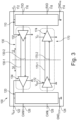
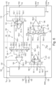
- Fig. 3 shows a schematic block diagram, and illustrates a core function, of a transceiver device 100 according to a first embodiment of the present invention, for interfacing between a first and a second supply voltage domain 12, 14.
- the transceiver device 100 has the first internal communication link 130, which comprises a first link transmitter 132, and a first link receiver 134, and which is capable to transfer the transmit data in the direction from the first interface 110 to the second interface 120.
- the transceiver device 100 further has the second internal communication link 170, which comprises a second link transmitter 172, and a second link receiver 174, and which is capable to transfer the receive data in the reverse direction from the second interface 120 to the first interface 110.
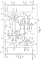
- Fig. 4 shows a schematic block diagram, and illustrates a core function, of a transceiver device 100 according to a second embodiment of the present invention, for interfacing between a first and a second supply voltage domain 12 and 14, wherein the first and the second internal communication links 130 and 170 use the principle of differential voltage transmission for the transmission of, respectively, the transmit data and receive data.
- the transceiver device 100 in respect of the transmission of transmit data and receive data, respectively, the first and the second internal communication link 130, 170 is indicated to be based on differential voltage transmission.
- the first internal communication link 130 is embodied a first differential voltage transmission link 140.
- the first link transmitter 132 is embodied as a first differential voltage transmitter 141, which operates with reference to, in particular is supplied by, the first supply voltage domain 12.
- the first differential voltage transmitter 141 is adapted to receive, via the first interface 110, the transmit data generated by the first digital device 20 operating in the first supply voltage domain 12, and is further adapted to generate and output a first differential voltage signal for transmitting the transmit data.
- the first link receiver 134 is embodied as a first differential voltage receiver 144, which operates with reference to, in particular is supplied by, the second supply voltage domain 14.
- the first differential voltage receiver 144 is adapted to receive the differential voltage signal transmitted by the first differential voltage transmitter 141, and is further adapted to transmit a first single-ended digital signal for transmitting the transmit data, via the second interface 120, to the external communication bus 24, which operates in the second supply voltage domain 14 and is embodied as CAN bus having a CAN high line 26 and a CAN low line 28.
- the first differential voltage transmitter 141 has a first switch-based H-bridge 142, which operates with reference to, in particular is supplied by, the first supply voltage domain 12, and the first differential voltage receiver 144 has a first voltage divider resistor ladder 145 and a first comparator 146, which operates with reference to, in particular is supplied by, the second supply voltage domain 14.
- the first switch-based H-bridge 142 comprises a first switch 142-1, a second switch 142-2, a third switch 142-3, and a fourth switch 142-4.
- the second switch 142-2 and the first switch 142-1 are connected in series, and the series connected second switch 142-2 and first switch 142-1 are connected between the first supply voltage Vio, which is supplied via the supply input pin 112, and the first domain ground GND 48 , which is supplied via the ground pin 114 of the first supply voltage.
- the fourth switch 142-4 and the third switch 142-3 are connected in series, and the series connected fourth switch 142-4 and third switch 142-3 are connected between the first supply voltage Vio, which is supplied via the supply input pin 112, and the first domain ground GND 48 , which is supplied via the ground pin 114 of the first supply voltage.
- the series connected second switch 142-2 and first switch 142-1 are connected in parallel to the series connected fourth switch 142-4 and third switch 142-3, between the first supply voltage Vio and first domain ground GND 48 .
- a first line 140-1 of the first differential communication link 140, or a first output of the first switch-based H-bridge 142 is connected to a connection point between the third switch 142-3 and the fourth switch 142-4.
- a second line 140-2 of the first communication link 140, or a second output of the first switch-based H-bridge 142 is connected to a connection point between the first switch 142-1 and the second switch 142-2.
- the first switch 142-1 and the third switch 142-3 are coupled in the sense that they are switched, i.e. opened and closed, simultaneously.
- the second switch 142-2 and the fourth switch 142-4 are coupled in the sense that they are switched, i.e. opened and closed, simultaneously.
- An input signal to the first switch-based H-bridge 142 switches, upon transition to a high state (or low state), the mutually coupled first switch 142-1 and third switch 142-3 simultaneously on and the mutually coupled second switch 142-2 and fourth switch 142-4 off.
- the input signal to the first switch-based H-bridge 142 switches, upon transition to a low state (or high state), the mutually coupled first switch 142-1 and third switch 142-3 simultaneously off and the mutually coupled second switch 142-2 and fourth switch 142-4 on.
- the first output line 140-1 of the first differential communication link 140 assumes the potential of the first domain ground (GND 48 ) 114, and the second output line 140-2 of the first differential communication link 140, assumes the potential of the first supply voltage (Vio) 112.
- the first output line 140-1 of the first differential communication link 140 assumes the potential of the first supply voltage (Vio) 112
- the second output line 140-2 of the first differential communication link 140 assumes the potential of the first domain ground (GND 48 ) 114.
- the first line 140-1 of the first differential communication link 140 and the second line 140-2 of the first differential communication link 140 always have an "opposite potential" relative to each other, and as such the first differential communication link 140 transmits a differential voltage, which carries the transmit data.
- the first voltage divider resistor ladder 145 has, connected in series, a first resistor 145-1 having substantially a second resistance value R2, a second resistor 145-2 having substantially a first resistance value R1, a third resistor 145-3 having substantially the first resistance value R1, and a fourth resistor 145-4 having substantially the second resistance value R2.
- the first differential voltage signal as output from the first switch-based H-bridge 142 via the first line 140-1 and the second line 140-2 of the first differential communication link 140, is applied across the series connection consisting of the first to fourth resistor 145-1 to145-4. Then, a first auxiliary differential voltage signal is output by the first voltage divider resistor ladder 145 from between a first connection point 145-5 connected between the first and the second resistor 145-1 and 145-2 and a second connection point 145-6 connected between the third and the fourth resistor 145-3 and 145-4. A third connection point 145-7 connected between the second and the third resistor 145-2 and 145-3 is connected to the second domain ground (GND 12/24 ) 124.
- the first comparator 146 has an input 146-1, an inverting input 146-2, and an output 146-3, and receives the first auxiliary differential voltage signal as applied to its input 146-1 and to its inverting input 146-2.
- the first comparator 146 outputs from its output 146-3 a first single-ended digital signal, which carries the transmit data.
- the second internal communication link 170 is embodied a second differential voltage transmission link 180.
- the second link transmitter 172 is embodied as a second differential voltage transmitter 181, which operates with reference to, in particular is supplied by, the second supply voltage domain 14.
- the second differential voltage transmitter 181 is adapted to receive, via the second interface 120, the receive data, which are supplied from the external communication bus 24 operating in the second supply voltage domain 14, and is further adapted to generate and output a second differential voltage signal for transmitting the receive data.
- the second link receiver 174 is embodied as a second differential voltage receiver 184, which operates with reference to, in particular is supplied by, the first supply voltage domain 12.
- the second differential voltage receiver 184 is adapted to receive the differential voltage signal transmitted by the second differential voltage transmitter 181, and is further adapted to transmit a second single-ended digital signal for transmitting the receive data, via the first interface 110, to the second digital device 22 operating in the first supply voltage domain 12.
- the second differential voltage transmitter 181 has a second switch-based H-bridge 182, which operates with reference to, in particular is supplied by, the second supply voltage domain 14, and the second differential voltage receiver 184 has a first voltage divider resistor ladder 185 and a first comparator 186, which operates with reference to, in particular is supplied by, the first supply voltage domain 12.
- the second switch-based H-bridge 182 comprises a first switch 182-1, a second switch 182-2, a third switch 182-3, and a fourth switch 182-4.
- the first switch 182-1 and the second switch 182-2 are connected in series, and the series connected first switch 182-1 and second switch 182-2 are connected between the second supply voltage V BUF , which is supplied via the supply input pin 122, and the second domain ground GND 12/24 , which is supplied via the ground pin 124 of the second supply voltage.
- the third switch 182-3 and the fourth switch 182-4 are connected in series, and the series connected third switch 182-3 and fourth switch 182-4 are connected between the second supply voltage V BUF , which is supplied via the supply input pin 122, and the second domain ground GND 12/24 , which is supplied via the ground pin 124 of the second supply voltage.
- the series connected first switch 182-1 and second switch 182-2 are connected in parallel to the series connected third switch 182-3 and fourth switch 182-4, between second first supply voltage V BUF and second domain ground GND 12/24 .
- a first line 180-1 of the second differential communication link 180, or a first output of the second switch-based H-bridge 182 is connected to a connection point between the third switch 182-3 and the fourth switch 182-4.
- a second line 180-2 of the second differential communication link 180, or a second output of the second switch-based H-bridge 182 is connected to a connection point between the first switch 182-1 and the second switch 182-2.
- the first switch 182-1 and the third switch 182-3 are coupled in the sense that they are switched, i.e. opened and closed, simultaneously.
- the second switch 182-2 and the fourth switch 182-4 are coupled in the sense that they are switched, i.e. opened and closed, simultaneously.
- An input signal to the first switch-based H-bridge 182 switches, upon transition to a high state (or low state), the mutually coupled first switch 182-1 and third switch 182-3 simultaneously on and the mutually coupled second switch 182-2 and fourth switch 182-4 off.
- the input signal to the first switch-based H-bridge 182 switches, upon transition to a low state (or high state), the mutually coupled first switch 182-1 and third switch 182-3 simultaneously off and the mutually coupled second switch 142-2 and fourth switch 182-4 on.
- the first output line 180-1 of the second differential communication link 180 assumes the potential of the second domain ground (GND 12/24 ) 124, and the second output line 180-2 of the second differential communication link 180, assumes the potential of the first supply voltage (V BUF ) 122.
- the first output line 180-1 of the second differential communication link 180 assumes the potential of the second supply voltage (V BUF ) 122, and the second output line 180-2 of the second differential communication link 180, assumes the potential of the second domain ground (GND 12/24 ) 124.
- the first line 180-1 of the second differential communication link 180 and the second line 180-2 of the second differential communication link 180 always have an "opposite potential" relative to each other, and as such the second differential communication link 180 transmits a differential voltage, which carries the receive data.
- the second voltage divider resistor ladder 185 has, connected in series, a first resistor 185-1 having substantially a second resistance value R2, a second resistor 185-2 having substantially a first resistance value R1, a third resistor 185-3 having substantially the first resistance value, and a fourth resistor 185-4 having substantially the second resistance value.
- the second differential voltage signal as output from the second switch-based H-bridge 182, is applied across the series connection consisting of the first to fourth resistor 185-1 to 185-4. Then, a second auxiliary differential voltage signal is output by the second voltage divider resistor ladder 185 from between a first connection point 185-5 connected between the first and the second resistor 185-1 and 185-2 and a second connection point 185-6 connected between the third and the fourth resistor 185-3 and 185-4.
- a third connection point 185-7 connected between the second and the third resistor 185-2 and 185-3 is connected to the first domain ground (GND 48 ) 114.
- the second comparator 186 has an input 186-1, an inverting input 186-2, and an output 186-3, and receives the second auxiliary differential voltage signal as applied to its input 186-1 and to its inverting input 186-2.
- the second comparator 186 outputs from its output 186-3 a second single-ended digital signal, which carries the receive data.
- Fig. 5 shows a schematic block diagram, and illustrates a core function, of a transceiver device 100 according to a third embodiment of the present invention, for interfacing between a first and a second supply voltage domain 12 and 14, wherein the first and the second internal communication links 130 and 170 use the principle of digital current loop transmission for the transmission of, respectively, the transmit data and receive data.
- the first internal communication link 130 is embodied as a first digital current loop transmission link 150, which has a first link transmitter 132 that is embodied a first transconductance transmitter 151.
- the first transconductance transmitter 151 operates with reference to, in particular is supplied by, the first supply voltage domain 12.
- the first transconductance transmitter 151 is adapted to receive, via the first interface 110, a first input voltage for carrying the transmit data generated by the first digital device 20 operating in the first supply voltage domain 12, and is further adapted to convert the first input voltage into, and output, a first differential current for transmitting the transmit data.
- the first differential current is in particular a two-way current, which is carried by the first line 150-1 and the second line 150-2 of the first digital current loop transmission link 150, to thereby form a two-way current loop, which is capable to represent dominant and recessive levels of a stream of transmit data.
- the first transconductance transmitter 151 may be based on an active H-bridge driver circuitry.
- the first link receiver 134 is embodied as a first digital differential current loop receiver 154, which operates with reference to, in particular is supplied by, the second supply voltage domain 14.
- the first digital differential current loop receiver 154 is adapted to receive the first differential current output, and is further adapted to convert this into, and output, a first single-ended digital signal for transmitting the transmit data, via the second interface 120, to the external communication bus 24 operating in the second supply voltage domain 14.
- the first digital differential current loop receiver 154 has a first voltage divider resistor ladder 155 and a first differential current loop voltage comparator 156, which operates with reference to, in particular is supplied by, the second supply voltage domain 14.
- the first voltage divider resistor ladder 155 has, connected in series, a first resistor 155-1 having substantially a second resistance value R2, a second resistor 155-2 having substantially a first resistance value R1, a third resistor 155-3 having substantially the first resistance value R1, and a fourth resistor 155-4 having substantially the second resistance value R2.
- the first differential current signal as output from the first transconductance transmitter 151, is applied across the series connection consisting of the first to fourth resistor 155-1 to 155-4. Then, a first auxiliary differential voltage signal is output by the first voltage divider resistor ladder 155 from between a first connection point 155-5 connected between the first and the second resistor 155-1 and 155-2 and a second connection point 155-6 connected between the third and the fourth resistor 155-3 and 155-4.
- a third connection point 155-7 between the second and the third resistor 155-2 and 155-3 may be connected to the second domain ground (GND 12/24 ) 124.
- the first differential current loop voltage comparator 156 has an input 156-1, an inverting input 156-2, and an output 156-3, and receives the first auxiliary differential voltage signal as applied to its input 156-1 and to its inverting input 156-2.
- the first differential current loop voltage comparator 156 outputs from its output 156-3 a first single-ended digital signal, which carries the transmit data.
- the transmit data are then further transmitted through the second interface 120 to the external communication bus 24 operating in the second supply voltage domain 14.
- the second internal communication link 170 is embodied as a second digital current loop transmission link 190, which has a second link transmitter 172 that is embodied as a second transconductance transmitter 191.
- the second transconductance transmitter 191 operates with reference to, in particular is supplied by, the second supply voltage domain 12. It is further adapted to receive, via the second interface 120, a second input voltage for carrying the receive data, which are supplied from the external communication bus 24 operating in the second supply voltage domain 14, and is further adapted to convert the second input voltage into, and output, a second differential, in particular two-way, current output for transmitting the receive data.
- the second differential current is in particular a two-way current, which is carried by the first line 190-1 and the second line 190-2 of the second digital current loop transmission link 190, to thereby form a two-way current loop, which is capable to represent dominant and recessive levels of a stream of receive data.
- the second transconductance transmitter 191 may be based on an active H-bridge driver circuitry.
- the second digital current loop transmission link 190 has a second link receiver 174 that is embodied as a second digital differential current loop receiver 194.
- the second digital differential current loop receiver 194 is adapted to receive the second differential current output, and is further adapted to convert this into, and output, a second single-ended digital signal for transmitting the receive data, via the first interface 110, to the second digital device 22 operating in the first supply voltage domain 12.
- the second digital differential current loop receiver 194 has a second voltage divider resistor ladder 195 and a second differential current loop voltage comparator 196, which operates with reference to, in particular is supplied by, the first supply voltage domain 12.
- the second voltage divider resistor ladder 195 has, connected in series, a first resistor 195-1 having substantially a second resistance value R2, a second resistor 195-2 having substantially a first resistance value R1, a third resistor 195-3 having substantially the first resistance value, and a fourth resistor 195-4 having substantially the second resistance value.
- the second differential current signal as output from the second transconductance transmitter 191, is applied across the series connection consisting of the first to fourth resistor 195-1 to 195-4. Then, a second auxiliary differential voltage signal is output by the second voltage divider resistor ladder 195 from between a first connection point 195-5 connected between the first and the second resistor 195-1 and 195-2 and a second connection point 195-6 connected between the third and the fourth resistor 195-3 and 195-4.
- a third connection point 195-7 between the second and the third resistor 195-2 and 195-3 may be connected to the first domain ground (GND 48 ) 114.
- the second differential current loop voltage comparator 196 has an input 196-1, an inverting input 196-2, and an output 196-3, and receives the first auxiliary differential voltage signal as applied to its input 196-1 and to its inverting input 196-2.
- the second differential current loop voltage comparator 196 outputs from its output 196-3 a second single-ended digital signal, which carries the receive data.
- the receive data are then further transmitted through the first interface 110 to the second digital device 22 operating in the first supply voltage domain 12.
- Fig. 6 shows a schematic block diagram, and illustrates a core function, of a transceiver device 100 according to the third embodiment of the present invention illustrated in Fig. 5 , showing details of the first and second transconductance transmitters 151, 191.
- the first transconductance transmitter 151 has a first branch having, connected in series, a first current source 151-1 adapted to generate a first electric current and a first switch 151-2, and a second branch having, connected in series, a second current source 151-3 adapted to generate a second electric current and a second switch 151-4.
- the first branch and the second branch are connected in parallel between a first connection point 152-1 and a second connection point 152-2.
- the second electric current is directed opposite to the first electric current.
- the first connection point 152-1 represents a first output that connects to a first output line 150-1 of the first digital current loop communication link 150
- the second connection point 152-2 represents a second output that connects to a second output line 150-2 of the first digital current loop communication link 150, which transfers the transmit data from the first interface 110 to the second interface 120.
- the second transconductance transmitter 191 has a first branch having, connected in series, a first current source 191-1 adapted to generate a first electric current and a first switch 191-2, and a second branch having, connected in series, a second current source 191-3 adapted to generate a second electric current and a second switch 191-4.
- the first branch and the second branch are connected in parallel between a first connection point 192-1 and a second connection point 192-2.
- the second electric current is directed opposite to the first electric current.
- the first connection point 192-1 represents a first output that connects to a first output line 190-1 of the second digital current loop communication link 190
- the second connection point 192-2 represents a second output that connects to a second output line 190-2 of the second digital current loop communication link 190, which transfers the receive data from the second interface 120 to the first interface 110.
Landscapes
- Engineering & Computer Science (AREA)
- Computer Networks & Wireless Communication (AREA)
- Signal Processing (AREA)
- Computer Hardware Design (AREA)
- Mechanical Engineering (AREA)
- Physics & Mathematics (AREA)
- Computing Systems (AREA)
- General Engineering & Computer Science (AREA)
- Mathematical Physics (AREA)
- Dc Digital Transmission (AREA)
Claims (10)
- Sendeempfängervorrichtung (100) zum Herstellen einer Verbindung zwischen mindestens zwei verschiedenen Spannungsdomänen (12, 14), nämlich einer ersten Versorgungsspannungsdomäne (12) mit einer höheren, ersten Versorgungsspannung, und einer zweiten Versorgungsspannungsdomäne (14) mit einer niedrigeren, zweiten Versorgungsspannung, wobei die Sendeempfängervorrichtung (100) aufweist:eine erste Schnittstelle (110), die von der ersten Versorgungsspannung versorgt wird und zum Herstellen einer Verbindung mit mindestens einer ersten externen digitalen Vorrichtung (20) ausgelegt ist, die in der ersten Versorgungsspannungsdomäne (12) funktioniert;eine zweite Schnittstelle (120), die von der zweiten Versorgungsspannung versorgt wird und zum Herstellen einer Verbindung mit einem externen Kommunikationsbus (24) ausgelegt ist, der in der zweiten Versorgungsspannungsdomäne (14) funktioniert;eine erste interne Kommunikationsverbindung (130), die dazu ausgelegt ist, Sendedaten, die von der ersten externen digitalen Vorrichtung (20), die in der ersten Versorgungsspannungsdomäne (12) funktioniert, erzeugt werden können, von der ersten Schnittstelle (110) an die zweite Schnittstelle (120) zu übertragen, undeine zweite interne Kommunikationsverbindung (170), die dazu ausgelegt ist, Empfangsdaten, die vom externen Kommunikationsbus (24), der in der zweiten Versorgungsspannungsdomäne funktioniert, geliefert werden können, von der zweiten Schnittstelle (120) an die erste Schnittstelle (110) zu übertragen,wobei die erste und die zweite interne Kommunikationsverbindung (130, 170) bezüglich der Übertragung von Sendedaten bzw. Empfangsdaten auf Differenzspannungsübertragung (140, 180) basieren, undwobei die erste interne Kommunikationsverbindung (130) umfasst:einen ersten Differenzspannungssender (141), der in Bezug auf die erste Versorgungsspannungsdomäne (12) funktioniert und der zum Empfangen der Sendedaten, die von der ersten externen digitalen Vorrichtung (20) erzeugt werden, die in der ersten Versorgungsspannungsdomäne (12) funktioniert, über die erste Schnittstelle (110) und zum Erzeugen und Ausgeben eines ersten Differenzspannungssignals zum Senden der Sendedaten ausgelegt ist,einen ersten Differenzspannungsempfänger (144), der in Bezug auf die zweite Versorgungsspannungsdomäne (14) funktioniert und der zum Empfangen des ersten Differenzspannungssignals, das vom ersten Differenzspannungssender (141) gesendet wird, und zum Senden eines ersten unsymmetrischen digitalen Signals zum Senden der Sendedaten über die zweite Schnittstelle (120) an den externen Kommunikationsbus (24) ausgelegt ist, der in der zweiten Versorgungsspannungsdomäne (14) funktioniert.
- Sendeempfängervorrichtung nach Anspruch 1, die mindestens eines der folgenden Merkmale aufweist:i) die Sendeempfängervorrichtung (100) ist als monolithische integrierte Schaltung realisiert;ii) die Sendeempfängervorrichtung (100) weist mindestens zwei Massestifte (114, 124) auf, die einen ersten Massestift (114), der dazu ausgelegt ist, an ein Massepotenzial der ersten Versorgungsspannungsdomäne (12) angeschlossen zu werden, und einen zweiten Massestift (124) umfasst, der dazu ausgelegt ist, an ein Massepotenzial der zweiten Versorgungsspannungsdomäne (14) angeschlossen zu werden;iii) die Sendeempfängervorrichtung (100) weist einen Gleichtaktmodus- und Masseversatzbereich auf, der in einem Bereich liegt, der bei mehr als ungefähr ±3 V beginnt, aber 170 V nicht überschreitet;iv) die erste Versorgungsspannung beträgt im Wesentlichen nominal 48 V oder mehr;v) die zweite Versorgungsspannung beträgt im Wesentlichen nominal 12 V oder im Wesentlichen nominal 24 V.
- Sendeempfängervorrichtung (100) nach Anspruch 1 oder 2, wobei die erste Schnittstelle (110) aufweist:einen Sendedateneingang (116), der dazu ausgelegt ist, die Sendedaten z. B. von der ersten digitalen Vorrichtung (20) zu empfangen, die in der ersten Versorgungsspannungsdomäne (12) funktioniert, undeinen Empfangsdatenausgang (118), der dazu ausgelegt ist, die Empfangsdaten z. B. an eine zweite digitale Vorrichtung (22) zu senden, die in der ersten Versorgungsspannungsdomäne (12) funktioniert.
- Sendeempfängervorrichtung (100) nach einem der Ansprüche 1 bis 3, wobei die zweite Schnittstelle (170) aufweist:
mindestens einen Kommunikationsbusstift (126, 128), der dazu ausgelegt ist, die Sendedaten an den Kommunikationsbus (24), der in der zweiten Versorgungsspannungsdomäne (14) funktioniert, zu senden und die Empfangsdaten davon zu empfangen. - Sendeempfängervorrichtung (100) nach Anspruch 1, wobei:der erste Differenzspannungssender (131, 141) eine schalterbasierte H-Brücke (142) aufweist, die in Bezug auf die erste Versorgungsspannungsdomäne (12) funktioniert, undder erste Differenzspannungsempfänger (134, 144) einen ersten Spannungsteiler-Widerstandskettenleiter (145) und einen ersten Komparator (146) aufweist, der in Bezug auf die zweite Versorgungsspannungsdomäne (14) funktioniert,wobei der erste Spannungsteiler-Widerstandskettenleiter (145) einen ersten Widerstand (145-1), der im Wesentlichen einen zweiten Widerstandswert (R2) aufweist, einen zweiten Widerstand (145-2), der im Wesentlichen einen ersten Widerstandswert (R1 ) aufweist, einen dritten Widerstand (145-3), der im Wesentlichen den ersten Widerstandswert (R1) aufweist, und einen vierten Widerstand (145-4), der im Wesentlichen den zweiten Widerstandswert (R2) aufweist, in Reihe geschaltet aufweist,wobei das erste Differenzspannungssignal als Ausgabe aus der ersten schalterbasierten H-Brücke (142) an die Reihenschaltung angelegt wird, die aus dem ersten bis vierten Widerstand (145-1, ..., 145-4) besteht, wobei ein erstes Hilfsdifferenzspannungssignal durch den ersten Spannungsteiler-Widerstandskettenleiter (145) von zwischen einem ersten Anschlusspunkt (145-5), der zwischen den ersten und den zweiten Widerstand (145-1, 145-2) geschaltet ist, und einem zweiten Anschlusspunkt (145-6), der zwischen den dritten und den vierten Widerstand (145-3, 145-4) geschaltet ist, ausgegeben wird, undwobei der erste Komparator (146) einen Eingang (146-1), einen invertierenden Eingang (146-2) und einen Ausgang (146-3) aufweist und das erste Hilfsdifferenzialspannungssignal empfängt, wie an seinen Eingang (146-1) und an seinen invertierenden Eingang (146-2) angelegt, und das erste unsymmetrische digitale Signal aus seinem Ausgang (146-3) ausgibt.
- Elektrisches Netzwerksystem (10) mit einer höheren, ersten Versorgungsspannungsdomäne (12) und einer niedrigeren, zweiten Versorgungsspannungsdomäne (14) und einer Sendeempfängervorrichtung (100) nach einem der Ansprüche 1 bis 5 zum Herstellen einer Verbindung zwischen der ersten und der zweiten Versorgungsspannungsdomäne (12, 14).
- Fahrzeug mit einem elektrischen Netzwerksystem (10) nach Anspruch 6.
- Verfahren zur Herstellung einer Verbindung zwischen mindestens zwei verschiedenen Spannungsdomänen (12, 14), nämlich einer ersten Versorgungsspannungsdomäne (12) mit einer höheren, ersten Versorgungsspannung und einer zweiten Versorgungsspannungsdomäne (14) mit einer niedrigeren, zweiten Versorgungsspannung, über eine Schnittstelle, wobei das Verfahren von einer Sendeempfängervorrichtung (100) mit einer ersten Schnittstelle (110), einer zweiten Schnittstelle (120), einem ersten internen Kommunikationskanal (130) und einem zweiten internen Kommunikationskanal (170) durchgeführt wird, wobei das Verfahren die folgenden Schritte umfasst:Versorgen der ersten Schnittstelle (110) mit der ersten Versorgungsspannung und Herstellen einer Verbindung durch die erste Schnittstelle (110) mit mindestens einer ersten externen digitalen Vorrichtung (20), die in der ersten Versorgungsspannungsdomäne (12) funktioniert;Versorgen der zweiten Schnittstelle (120) mit der zweiten Versorgungsspannung und Herstellen einer Verbindung durch die zweite Schnittstelle (120) mit einem externen Kommunikationsbus (24), der in der zweiten Versorgungsspannungsdomäne (14) funktioniert;Übertragen von Sendedaten, die von der ersten externen digitalen Vorrichtung (20), die in der ersten Versorgungsspannungsdomäne (12) funktioniert, erzeugt werden, durch die erste Schnittstelle (110) über die erste interne Kommunikationsverbindung (130) an die zweite Schnittstelle (120); undÜbertragen von Empfangsdaten, die vom externen Kommunikationsbus (24), der in der zweiten Versorgungsspannungsdomäne funktioniert, geliefert werden, durch die zweiten Schnittstelle (120) über die zweite interne Kommunikationsverbindung (170) an die erste Schnittstelle (110),wobei die erste und die zweite interne Kommunikationsverbindung (130, 170) bezüglich der Übertragung von Sendedaten bzw. der Empfangsdaten auf Differenzspannungsübertragung (140, 180) basieren, undwobei die erste interne Kommunikationsverbindung (130) umfasst:einen ersten Differenzspannungssender (141), der in Bezug auf die erste Versorgungsspannungsdomäne (12) funktioniert und der zum Empfangen der Sendedaten, die von der ersten externen digitalen Vorrichtung (20) erzeugt werden, die in der ersten Versorgungsspannungsdomäne (12) funktioniert, über die erste Schnittstelle (110) und zum Erzeugen und Ausgeben eines ersten Differenzspannungssignal zum Senden der Sendedaten ausgelegt ist,einen ersten Differenzspannungsempfänger (144), der in Bezug auf die zweite Versorgungsspannungsdomäne (14) funktioniert und der zum Empfangen des ersten Differenzspannungssignals, das vom ersten Differenzspannungssender (141) gesendet wird, und zum Senden eines ersten unsymmetrischen digitalen Signals zum Senden der Sendedaten über die zweite Schnittstelle (120) an den externen Kommunikationsbus (24) ausgelegt ist, der in der zweiten Versorgungsspannungsdomäne (14) funktioniert.
- Verfahren nach Anspruch 8, ferner umfassend:i) Betreiben der ersten und der zweiten internen Kommunikationsverbindung (130, 140; 170, 180) in einem Differenzspannungsübertragungsmodus.
- Verfahren nach Anspruch 8 oder 9, das mindestens eines der folgenden Merkmale aufweist:i) die erste Schnittstelle (110), die erste und die zweite interne Kommunikationsschnittstelle (130, 170) und die zweite Schnittstelle (120) sind als monolithische integrierte Schaltung realisiert;ii) die Sendeempfängervorrichtung (100) weist mindestens zwei Massestifte (114, 124) auf, die einen ersten Massestift (114), der dazu ausgelegt ist, an ein Massepotenzial der ersten Versorgungsspannungsdomäne (12) angeschlossen zu werden, und einen zweiten Massestift (124) umfasst, der dazu ausgelegt ist, an ein Massepotenzial der zweiten Versorgungsspannungsdomäne (14) angeschlossen zu werden;iii) die Sendeempfängervorrichtung (100) weist einen Gleichtaktmodus- und Masseversatzbereich auf, der in einem Bereich liegt, der bei mehr als ungefähr ±3 V beginnt, aber 170 V nicht überschreitet;iv) die erste Versorgungsspannung beträgt im Wesentlichen nominal 48 V oder mehr;v) die zweite Versorgungsspannung beträgt im Wesentlichen nominal 12 V oder im Wesentlichen nominal 24 V.
Priority Applications (3)
| Application Number | Priority Date | Filing Date | Title |
|---|---|---|---|
| EP20155913.5A EP3863232B1 (de) | 2020-02-06 | 2020-02-06 | Mit zwei verschiedenen versorgungsspannungsdomänen verbundener monolithischer hochspannungs-sendeempfänger |
| CN202110114717.9A CN113225066B (zh) | 2020-02-06 | 2021-01-27 | 连接到两个不同的电源电压域的单片高压收发器 |
| US17/248,675 US11516043B2 (en) | 2020-02-06 | 2021-02-02 | Monolithic high-voltage transceiver connected to two different supply voltage domains |
Applications Claiming Priority (1)
| Application Number | Priority Date | Filing Date | Title |
|---|---|---|---|
| EP20155913.5A EP3863232B1 (de) | 2020-02-06 | 2020-02-06 | Mit zwei verschiedenen versorgungsspannungsdomänen verbundener monolithischer hochspannungs-sendeempfänger |
Publications (2)
| Publication Number | Publication Date |
|---|---|
| EP3863232A1 EP3863232A1 (de) | 2021-08-11 |
| EP3863232B1 true EP3863232B1 (de) | 2023-06-21 |
Family
ID=69526086
Family Applications (1)
| Application Number | Title | Priority Date | Filing Date |
|---|---|---|---|
| EP20155913.5A Active EP3863232B1 (de) | 2020-02-06 | 2020-02-06 | Mit zwei verschiedenen versorgungsspannungsdomänen verbundener monolithischer hochspannungs-sendeempfänger |
Country Status (3)
| Country | Link |
|---|---|
| US (1) | US11516043B2 (de) |
| EP (1) | EP3863232B1 (de) |
| CN (1) | CN113225066B (de) |
Families Citing this family (7)
| Publication number | Priority date | Publication date | Assignee | Title |
|---|---|---|---|---|
| US11855641B2 (en) * | 2020-07-07 | 2023-12-26 | Infineon Technologies LLC | Integrated resistor network and method for fabricating the same |
| EP4099641A1 (de) * | 2021-06-03 | 2022-12-07 | Nxp B.V. | Sendeempfängervorrichtung |
| CN113985147A (zh) * | 2021-10-29 | 2022-01-28 | 奇瑞商用车(安徽)有限公司 | 车辆的地偏移检测装置及方法 |
| US20240322733A1 (en) * | 2021-11-12 | 2024-09-26 | Mitsubishi Electric Corporation | Electronic control device and electric power steering device |
| CN116662239B (zh) * | 2023-08-01 | 2023-12-22 | 北京国科天迅科技股份有限公司 | 高速串行接口装置 |
| EP4679775A1 (de) * | 2024-07-11 | 2026-01-14 | Hella Gmbh & Co. Kgaa | Spannungspegelumsetzer und batteriesystem |
| EP4723493A1 (de) * | 2024-10-07 | 2026-04-08 | ZF CV Systems Global GmbH | System und verfahren für eine fahrzeugkommunikationsvorrichtung mit einem spannungsverschiebungsmodul |
Family Cites Families (14)
| Publication number | Priority date | Publication date | Assignee | Title |
|---|---|---|---|---|
| AU2001280067A1 (en) * | 2000-08-14 | 2002-02-25 | Main.Net Communication | Power line communication system |
| DE602004011188T2 (de) * | 2003-02-13 | 2008-12-24 | Nxp B.V. | Anordnung zur masseversatzkompensation in einem datenbussystem |
| US20060290404A1 (en) | 2005-06-23 | 2006-12-28 | Ati Technologies Inc. | Apparatus and methods for voltage level conversion |
| JP4682878B2 (ja) * | 2006-03-06 | 2011-05-11 | 株式会社デンソー | 電子制御装置 |
| JP6105868B2 (ja) * | 2012-06-26 | 2017-03-29 | 株式会社不二工機 | 電動弁制御装置及び電動弁装置 |
| TW201505396A (zh) * | 2013-07-29 | 2015-02-01 | 世紀民生科技股份有限公司 | 控制器區域網路節點收發器 |
| US10169278B2 (en) * | 2013-07-31 | 2019-01-01 | Infineon Technologies Ag | LIN bus module |
| WO2017032391A1 (en) * | 2015-08-21 | 2017-03-02 | Telefonaktiebolaget Lm Ericsson (Publ) | Signal distribution network |
| US10678837B2 (en) * | 2016-05-13 | 2020-06-09 | Wayne Fueling Systems Llc | Management of fuel dispenser media |
| WO2018086837A1 (en) * | 2016-11-11 | 2018-05-17 | Siemens Aktiengesellschaft | Transport assembly |
| WO2018104929A1 (en) * | 2016-12-07 | 2018-06-14 | Arilou Information Security Technologies Ltd. | System and method for using signal waveform analysis for detecting a change in a wired network |
| CN108924025B (zh) * | 2018-07-11 | 2020-09-01 | 西安电子科技大学 | 携能现场总线模块及其系统 |
| EP3598409B1 (de) * | 2018-07-16 | 2021-03-10 | Melexis Technologies NV | Sende-empfänger mit mitteln zur galvanischen isolation |
| US10817458B2 (en) * | 2018-09-25 | 2020-10-27 | Analog Devices International Unlimited Company | Bidirectional signal separation |
-
2020
- 2020-02-06 EP EP20155913.5A patent/EP3863232B1/de active Active
-
2021
- 2021-01-27 CN CN202110114717.9A patent/CN113225066B/zh active Active
- 2021-02-02 US US17/248,675 patent/US11516043B2/en active Active
Also Published As
| Publication number | Publication date |
|---|---|
| CN113225066B (zh) | 2025-12-05 |
| US20210250199A1 (en) | 2021-08-12 |
| EP3863232A1 (de) | 2021-08-11 |
| CN113225066A (zh) | 2021-08-06 |
| US11516043B2 (en) | 2022-11-29 |
Similar Documents
| Publication | Publication Date | Title |
|---|---|---|
| EP3863232A1 (de) | Mit zwei verschiedenen versorgungsspannungsdomänen verbundener monolithischer hochspannungs-sendeempfänger | |
| KR101974713B1 (ko) | 중복 전원 연결을 이용한 데이터 라인 시스템에서 전원 공급 | |
| US8279883B2 (en) | High speed isolation interface for PoE | |
| CN106464558B (zh) | 用于总线系统的用户站和用于在用户站的电磁兼容性的范围内提高抗扰度的方法 | |
| EP2805214B1 (de) | Vorrichtung und verfahren für den betrieb einer ethernet-midspan-vorrichtung und ethernet-endspan-vorrichtung | |
| US7778409B2 (en) | Enabling cisco legacy power to support IEEE 802.3 AF standard power | |
| US8566415B2 (en) | Safe torque off over network wiring | |
| US9216706B2 (en) | Network and method for operating a network | |
| EP4207691B1 (de) | Abschlussschema für ein steuergerätebereichsnetzwerk | |
| WO2017013829A1 (ja) | 通信システム | |
| EP3723266A1 (de) | Stromversorgungsschaltung, relaisvorrichtung und power-over-ethernet-system | |
| WO2025138792A1 (zh) | 对称性调节模块及调节对称性的方法 | |
| US6328480B1 (en) | Connectors for providing fibre optic connection to Ethernet devices having twisted-pair connections | |
| US9442543B2 (en) | Network and method for operating a network | |
| US6404326B1 (en) | Redundant power communications circuit | |
| KR102436965B1 (ko) | PoE 확장 기능을 가지는 PoE 슬레이브 장치 | |
| CN209980093U (zh) | 一种车辆第一电源电机控制器隔离保护电路、车用电机控制器隔离保护模块和系统 | |
| WO2011057023A1 (en) | Driver circuit and system | |
| EP1989630B1 (de) | Schnittstelle zwischen bussen verschiedener physikalischer schichten | |
| JPH10294750A (ja) | 多重通信装置 | |
| NL2026452B1 (nl) | Inrichting voor een deelnemerstation van een serieel bussysteem en werkwijze voor communicatie in een serieel bussysteem | |
| US20070217548A1 (en) | Circuit Arrangement and Method of Operating Such Circuit Arrangement | |
| CN113812121A (zh) | 分配器装置和方法 | |
| CN120151132A (zh) | 用于串行总线系统的参与站以及用于利用差分信号在串行总线系统中通信的方法 | |
| Rath et al. | A two wire power over Ethernet approach for in-vehicle applications |
Legal Events
| Date | Code | Title | Description |
|---|---|---|---|
| PUAI | Public reference made under article 153(3) epc to a published international application that has entered the european phase |
Free format text: ORIGINAL CODE: 0009012 |
|
| STAA | Information on the status of an ep patent application or granted ep patent |
Free format text: STATUS: THE APPLICATION HAS BEEN PUBLISHED |
|
| AK | Designated contracting states |
Kind code of ref document: A1 Designated state(s): AL AT BE BG CH CY CZ DE DK EE ES FI FR GB GR HR HU IE IS IT LI LT LU LV MC MK MT NL NO PL PT RO RS SE SI SK SM TR |
|
| STAA | Information on the status of an ep patent application or granted ep patent |
Free format text: STATUS: REQUEST FOR EXAMINATION WAS MADE |
|
| 17P | Request for examination filed |
Effective date: 20220211 |
|
| RBV | Designated contracting states (corrected) |
Designated state(s): AL AT BE BG CH CY CZ DE DK EE ES FI FR GB GR HR HU IE IS IT LI LT LU LV MC MK MT NL NO PL PT RO RS SE SI SK SM TR |
|
| GRAP | Despatch of communication of intention to grant a patent |
Free format text: ORIGINAL CODE: EPIDOSNIGR1 |
|
| STAA | Information on the status of an ep patent application or granted ep patent |
Free format text: STATUS: GRANT OF PATENT IS INTENDED |
|
| RIC1 | Information provided on ipc code assigned before grant |
Ipc: H04L 12/40 20060101AFI20230202BHEP |
|
| INTG | Intention to grant announced |
Effective date: 20230227 |
|
| GRAS | Grant fee paid |
Free format text: ORIGINAL CODE: EPIDOSNIGR3 |
|
| GRAA | (expected) grant |
Free format text: ORIGINAL CODE: 0009210 |
|
| STAA | Information on the status of an ep patent application or granted ep patent |
Free format text: STATUS: THE PATENT HAS BEEN GRANTED |
|
| AK | Designated contracting states |
Kind code of ref document: B1 Designated state(s): AL AT BE BG CH CY CZ DE DK EE ES FI FR GB GR HR HU IE IS IT LI LT LU LV MC MK MT NL NO PL PT RO RS SE SI SK SM TR |
|
| REG | Reference to a national code |
Ref country code: CH Ref legal event code: EP |
|
| REG | Reference to a national code |
Ref country code: DE Ref legal event code: R096 Ref document number: 602020012634 Country of ref document: DE |
|
| REG | Reference to a national code |
Ref country code: AT Ref legal event code: REF Ref document number: 1581712 Country of ref document: AT Kind code of ref document: T Effective date: 20230715 |
|
| REG | Reference to a national code |
Ref country code: IE Ref legal event code: FG4D |
|
| REG | Reference to a national code |
Ref country code: LT Ref legal event code: MG9D |
|
| P01 | Opt-out of the competence of the unified patent court (upc) registered |
Effective date: 20230907 |
|
| REG | Reference to a national code |
Ref country code: NL Ref legal event code: MP Effective date: 20230621 |
|
| PG25 | Lapsed in a contracting state [announced via postgrant information from national office to epo] |
Ref country code: SE Free format text: LAPSE BECAUSE OF FAILURE TO SUBMIT A TRANSLATION OF THE DESCRIPTION OR TO PAY THE FEE WITHIN THE PRESCRIBED TIME-LIMIT Effective date: 20230621 Ref country code: NO Free format text: LAPSE BECAUSE OF FAILURE TO SUBMIT A TRANSLATION OF THE DESCRIPTION OR TO PAY THE FEE WITHIN THE PRESCRIBED TIME-LIMIT Effective date: 20230921 |
|
| REG | Reference to a national code |
Ref country code: AT Ref legal event code: MK05 Ref document number: 1581712 Country of ref document: AT Kind code of ref document: T Effective date: 20230621 |
|
| PG25 | Lapsed in a contracting state [announced via postgrant information from national office to epo] |
Ref country code: RS Free format text: LAPSE BECAUSE OF FAILURE TO SUBMIT A TRANSLATION OF THE DESCRIPTION OR TO PAY THE FEE WITHIN THE PRESCRIBED TIME-LIMIT Effective date: 20230621 Ref country code: NL Free format text: LAPSE BECAUSE OF FAILURE TO SUBMIT A TRANSLATION OF THE DESCRIPTION OR TO PAY THE FEE WITHIN THE PRESCRIBED TIME-LIMIT Effective date: 20230621 Ref country code: LV Free format text: LAPSE BECAUSE OF FAILURE TO SUBMIT A TRANSLATION OF THE DESCRIPTION OR TO PAY THE FEE WITHIN THE PRESCRIBED TIME-LIMIT Effective date: 20230621 Ref country code: LT Free format text: LAPSE BECAUSE OF FAILURE TO SUBMIT A TRANSLATION OF THE DESCRIPTION OR TO PAY THE FEE WITHIN THE PRESCRIBED TIME-LIMIT Effective date: 20230621 Ref country code: HR Free format text: LAPSE BECAUSE OF FAILURE TO SUBMIT A TRANSLATION OF THE DESCRIPTION OR TO PAY THE FEE WITHIN THE PRESCRIBED TIME-LIMIT Effective date: 20230621 Ref country code: GR Free format text: LAPSE BECAUSE OF FAILURE TO SUBMIT A TRANSLATION OF THE DESCRIPTION OR TO PAY THE FEE WITHIN THE PRESCRIBED TIME-LIMIT Effective date: 20230922 |
|
| PG25 | Lapsed in a contracting state [announced via postgrant information from national office to epo] |
Ref country code: FI Free format text: LAPSE BECAUSE OF FAILURE TO SUBMIT A TRANSLATION OF THE DESCRIPTION OR TO PAY THE FEE WITHIN THE PRESCRIBED TIME-LIMIT Effective date: 20230621 |
|
| PG25 | Lapsed in a contracting state [announced via postgrant information from national office to epo] |
Ref country code: SK Free format text: LAPSE BECAUSE OF FAILURE TO SUBMIT A TRANSLATION OF THE DESCRIPTION OR TO PAY THE FEE WITHIN THE PRESCRIBED TIME-LIMIT Effective date: 20230621 |
|
| PG25 | Lapsed in a contracting state [announced via postgrant information from national office to epo] |
Ref country code: ES Free format text: LAPSE BECAUSE OF FAILURE TO SUBMIT A TRANSLATION OF THE DESCRIPTION OR TO PAY THE FEE WITHIN THE PRESCRIBED TIME-LIMIT Effective date: 20230621 |
|
| PG25 | Lapsed in a contracting state [announced via postgrant information from national office to epo] |
Ref country code: IS Free format text: LAPSE BECAUSE OF FAILURE TO SUBMIT A TRANSLATION OF THE DESCRIPTION OR TO PAY THE FEE WITHIN THE PRESCRIBED TIME-LIMIT Effective date: 20231021 |
|
| PG25 | Lapsed in a contracting state [announced via postgrant information from national office to epo] |
Ref country code: SM Free format text: LAPSE BECAUSE OF FAILURE TO SUBMIT A TRANSLATION OF THE DESCRIPTION OR TO PAY THE FEE WITHIN THE PRESCRIBED TIME-LIMIT Effective date: 20230621 Ref country code: SK Free format text: LAPSE BECAUSE OF FAILURE TO SUBMIT A TRANSLATION OF THE DESCRIPTION OR TO PAY THE FEE WITHIN THE PRESCRIBED TIME-LIMIT Effective date: 20230621 Ref country code: RO Free format text: LAPSE BECAUSE OF FAILURE TO SUBMIT A TRANSLATION OF THE DESCRIPTION OR TO PAY THE FEE WITHIN THE PRESCRIBED TIME-LIMIT Effective date: 20230621 Ref country code: PT Free format text: LAPSE BECAUSE OF FAILURE TO SUBMIT A TRANSLATION OF THE DESCRIPTION OR TO PAY THE FEE WITHIN THE PRESCRIBED TIME-LIMIT Effective date: 20231023 Ref country code: IS Free format text: LAPSE BECAUSE OF FAILURE TO SUBMIT A TRANSLATION OF THE DESCRIPTION OR TO PAY THE FEE WITHIN THE PRESCRIBED TIME-LIMIT Effective date: 20231021 Ref country code: ES Free format text: LAPSE BECAUSE OF FAILURE TO SUBMIT A TRANSLATION OF THE DESCRIPTION OR TO PAY THE FEE WITHIN THE PRESCRIBED TIME-LIMIT Effective date: 20230621 Ref country code: EE Free format text: LAPSE BECAUSE OF FAILURE TO SUBMIT A TRANSLATION OF THE DESCRIPTION OR TO PAY THE FEE WITHIN THE PRESCRIBED TIME-LIMIT Effective date: 20230621 Ref country code: CZ Free format text: LAPSE BECAUSE OF FAILURE TO SUBMIT A TRANSLATION OF THE DESCRIPTION OR TO PAY THE FEE WITHIN THE PRESCRIBED TIME-LIMIT Effective date: 20230621 Ref country code: AT Free format text: LAPSE BECAUSE OF FAILURE TO SUBMIT A TRANSLATION OF THE DESCRIPTION OR TO PAY THE FEE WITHIN THE PRESCRIBED TIME-LIMIT Effective date: 20230621 |
|
| PG25 | Lapsed in a contracting state [announced via postgrant information from national office to epo] |
Ref country code: PL Free format text: LAPSE BECAUSE OF FAILURE TO SUBMIT A TRANSLATION OF THE DESCRIPTION OR TO PAY THE FEE WITHIN THE PRESCRIBED TIME-LIMIT Effective date: 20230621 |
|
| REG | Reference to a national code |
Ref country code: DE Ref legal event code: R097 Ref document number: 602020012634 Country of ref document: DE |
|
| PLBE | No opposition filed within time limit |
Free format text: ORIGINAL CODE: 0009261 |
|
| STAA | Information on the status of an ep patent application or granted ep patent |
Free format text: STATUS: NO OPPOSITION FILED WITHIN TIME LIMIT |
|
| PG25 | Lapsed in a contracting state [announced via postgrant information from national office to epo] |
Ref country code: DK Free format text: LAPSE BECAUSE OF FAILURE TO SUBMIT A TRANSLATION OF THE DESCRIPTION OR TO PAY THE FEE WITHIN THE PRESCRIBED TIME-LIMIT Effective date: 20230621 |
|
| PG25 | Lapsed in a contracting state [announced via postgrant information from national office to epo] |
Ref country code: SI Free format text: LAPSE BECAUSE OF FAILURE TO SUBMIT A TRANSLATION OF THE DESCRIPTION OR TO PAY THE FEE WITHIN THE PRESCRIBED TIME-LIMIT Effective date: 20230621 |
|
| 26N | No opposition filed |
Effective date: 20240322 |
|
| PG25 | Lapsed in a contracting state [announced via postgrant information from national office to epo] |
Ref country code: SI Free format text: LAPSE BECAUSE OF FAILURE TO SUBMIT A TRANSLATION OF THE DESCRIPTION OR TO PAY THE FEE WITHIN THE PRESCRIBED TIME-LIMIT Effective date: 20230621 Ref country code: IT Free format text: LAPSE BECAUSE OF FAILURE TO SUBMIT A TRANSLATION OF THE DESCRIPTION OR TO PAY THE FEE WITHIN THE PRESCRIBED TIME-LIMIT Effective date: 20230621 |
|
| PG25 | Lapsed in a contracting state [announced via postgrant information from national office to epo] |
Ref country code: MC Free format text: LAPSE BECAUSE OF FAILURE TO SUBMIT A TRANSLATION OF THE DESCRIPTION OR TO PAY THE FEE WITHIN THE PRESCRIBED TIME-LIMIT Effective date: 20230621 |
|
| REG | Reference to a national code |
Ref country code: CH Ref legal event code: PL |
|
| PG25 | Lapsed in a contracting state [announced via postgrant information from national office to epo] |
Ref country code: LU Free format text: LAPSE BECAUSE OF NON-PAYMENT OF DUE FEES Effective date: 20240206 |
|
| PG25 | Lapsed in a contracting state [announced via postgrant information from national office to epo] |
Ref country code: CH Free format text: LAPSE BECAUSE OF NON-PAYMENT OF DUE FEES Effective date: 20240229 |
|
| GBPC | Gb: european patent ceased through non-payment of renewal fee |
Effective date: 20240206 |
|
| PG25 | Lapsed in a contracting state [announced via postgrant information from national office to epo] |
Ref country code: LU Free format text: LAPSE BECAUSE OF NON-PAYMENT OF DUE FEES Effective date: 20240206 Ref country code: CH Free format text: LAPSE BECAUSE OF NON-PAYMENT OF DUE FEES Effective date: 20240229 |
|
| PG25 | Lapsed in a contracting state [announced via postgrant information from national office to epo] |
Ref country code: BG Free format text: LAPSE BECAUSE OF FAILURE TO SUBMIT A TRANSLATION OF THE DESCRIPTION OR TO PAY THE FEE WITHIN THE PRESCRIBED TIME-LIMIT Effective date: 20230621 |
|
| PG25 | Lapsed in a contracting state [announced via postgrant information from national office to epo] |
Ref country code: BG Free format text: LAPSE BECAUSE OF FAILURE TO SUBMIT A TRANSLATION OF THE DESCRIPTION OR TO PAY THE FEE WITHIN THE PRESCRIBED TIME-LIMIT Effective date: 20230621 |
|
| REG | Reference to a national code |
Ref country code: BE Ref legal event code: MM Effective date: 20240229 |
|
| PG25 | Lapsed in a contracting state [announced via postgrant information from national office to epo] |
Ref country code: BE Free format text: LAPSE BECAUSE OF NON-PAYMENT OF DUE FEES Effective date: 20240229 |
|
| PG25 | Lapsed in a contracting state [announced via postgrant information from national office to epo] |
Ref country code: GB Free format text: LAPSE BECAUSE OF NON-PAYMENT OF DUE FEES Effective date: 20240206 |
|
| PG25 | Lapsed in a contracting state [announced via postgrant information from national office to epo] |
Ref country code: IE Free format text: LAPSE BECAUSE OF NON-PAYMENT OF DUE FEES Effective date: 20240206 |
|
| PG25 | Lapsed in a contracting state [announced via postgrant information from national office to epo] |
Ref country code: IE Free format text: LAPSE BECAUSE OF NON-PAYMENT OF DUE FEES Effective date: 20240206 Ref country code: GB Free format text: LAPSE BECAUSE OF NON-PAYMENT OF DUE FEES Effective date: 20240206 Ref country code: BE Free format text: LAPSE BECAUSE OF NON-PAYMENT OF DUE FEES Effective date: 20240229 |
|
| PG25 | Lapsed in a contracting state [announced via postgrant information from national office to epo] |
Ref country code: CY Free format text: LAPSE BECAUSE OF FAILURE TO SUBMIT A TRANSLATION OF THE DESCRIPTION OR TO PAY THE FEE WITHIN THE PRESCRIBED TIME-LIMIT; INVALID AB INITIO Effective date: 20200206 |
|
| PG25 | Lapsed in a contracting state [announced via postgrant information from national office to epo] |
Ref country code: HU Free format text: LAPSE BECAUSE OF FAILURE TO SUBMIT A TRANSLATION OF THE DESCRIPTION OR TO PAY THE FEE WITHIN THE PRESCRIBED TIME-LIMIT; INVALID AB INITIO Effective date: 20200206 |
|
| PG25 | Lapsed in a contracting state [announced via postgrant information from national office to epo] |
Ref country code: TR Free format text: LAPSE BECAUSE OF FAILURE TO SUBMIT A TRANSLATION OF THE DESCRIPTION OR TO PAY THE FEE WITHIN THE PRESCRIBED TIME-LIMIT Effective date: 20230621 |
|
| PGFP | Annual fee paid to national office [announced via postgrant information from national office to epo] |
Ref country code: DE Payment date: 20260121 Year of fee payment: 7 |
|
| PGFP | Annual fee paid to national office [announced via postgrant information from national office to epo] |
Ref country code: FR Payment date: 20260121 Year of fee payment: 7 |