EP3862782A1 - Vorrichtung und verfahren zur korrektur eines eingangssignals - Google Patents
Vorrichtung und verfahren zur korrektur eines eingangssignals Download PDFInfo
- Publication number
- EP3862782A1 EP3862782A1 EP20155343.5A EP20155343A EP3862782A1 EP 3862782 A1 EP3862782 A1 EP 3862782A1 EP 20155343 A EP20155343 A EP 20155343A EP 3862782 A1 EP3862782 A1 EP 3862782A1
- Authority
- EP
- European Patent Office
- Prior art keywords
- series
- values
- signal
- input
- template
- Prior art date
- Legal status (The legal status is an assumption and is not a legal conclusion. Google has not performed a legal analysis and makes no representation as to the accuracy of the status listed.)
- Pending
Links
Images


Classifications
-
- G—PHYSICS
- G01—MEASURING; TESTING
- G01S—RADIO DIRECTION-FINDING; RADIO NAVIGATION; DETERMINING DISTANCE OR VELOCITY BY USE OF RADIO WAVES; LOCATING OR PRESENCE-DETECTING BY USE OF THE REFLECTION OR RERADIATION OF RADIO WAVES; ANALOGOUS ARRANGEMENTS USING OTHER WAVES
- G01S7/00—Details of systems according to groups G01S13/00, G01S15/00, G01S17/00
- G01S7/52—Details of systems according to groups G01S13/00, G01S15/00, G01S17/00 of systems according to group G01S15/00
- G01S7/523—Details of pulse systems
- G01S7/526—Receivers
- G01S7/527—Extracting wanted echo signals
- G01S7/5273—Extracting wanted echo signals using digital techniques
-
- H—ELECTRICITY
- H04—ELECTRIC COMMUNICATION TECHNIQUE
- H04B—TRANSMISSION
- H04B1/00—Details of transmission systems, not covered by a single one of groups H04B3/00 - H04B13/00; Details of transmission systems not characterised by the medium used for transmission
- H04B1/06—Receivers
- H04B1/10—Means associated with receiver for limiting or suppressing noise or interference
-
- G—PHYSICS
- G01—MEASURING; TESTING
- G01S—RADIO DIRECTION-FINDING; RADIO NAVIGATION; DETERMINING DISTANCE OR VELOCITY BY USE OF RADIO WAVES; LOCATING OR PRESENCE-DETECTING BY USE OF THE REFLECTION OR RERADIATION OF RADIO WAVES; ANALOGOUS ARRANGEMENTS USING OTHER WAVES
- G01S15/00—Systems using the reflection or reradiation of acoustic waves, e.g. sonar systems
- G01S15/02—Systems using the reflection or reradiation of acoustic waves, e.g. sonar systems using reflection of acoustic waves
- G01S15/06—Systems determining the position data of a target
- G01S15/08—Systems for measuring distance only
- G01S15/10—Systems for measuring distance only using transmission of interrupted, pulse-modulated waves
-
- G—PHYSICS
- G01—MEASURING; TESTING
- G01S—RADIO DIRECTION-FINDING; RADIO NAVIGATION; DETERMINING DISTANCE OR VELOCITY BY USE OF RADIO WAVES; LOCATING OR PRESENCE-DETECTING BY USE OF THE REFLECTION OR RERADIATION OF RADIO WAVES; ANALOGOUS ARRANGEMENTS USING OTHER WAVES
- G01S7/00—Details of systems according to groups G01S13/00, G01S15/00, G01S17/00
- G01S7/52—Details of systems according to groups G01S13/00, G01S15/00, G01S17/00 of systems according to group G01S15/00
- G01S7/52004—Means for monitoring or calibrating
-
- G—PHYSICS
- G06—COMPUTING; CALCULATING OR COUNTING
- G06F—ELECTRIC DIGITAL DATA PROCESSING
- G06F2218/00—Aspects of pattern recognition specially adapted for signal processing
- G06F2218/02—Preprocessing
- G06F2218/04—Denoising
-
- G—PHYSICS
- G06—COMPUTING; CALCULATING OR COUNTING
- G06F—ELECTRIC DIGITAL DATA PROCESSING
- G06F2218/00—Aspects of pattern recognition specially adapted for signal processing
- G06F2218/12—Classification; Matching
- G06F2218/16—Classification; Matching by matching signal segments
Definitions
- Embodiments of the present disclosure relate to an apparatus for correcting a signal and a method for correcting a signal. Further embodiments relate to an apparatus for obtaining an information about a time of flight of an ultrasonic signal. In particular, embodiments of the present disclosure relate to dynamic time warping for ultrasonic ringing template matching. Some embodiments relate to an adaptive ringing removal approach, based on Dynamic Time Warping (DTW) for template matching.
- DTW Dynamic Time Warping
- a signal which may represent a measured size, may be corrupted by a noise signal superposing the signal or interfering with the signal.
- a noise signal For extracting an information about the measured size from the signal, it may be necessary to correct the signal for the noise signal, in particular, if a signal to noise ratio of the signal is low.
- the source of the noise signal may be inherent to a system providing the signal so that the noise signal may reoccur in similar forms in subsequent sequences of the signal.
- the noise signal may be approximated by a template which may be used to correct the signal for the noise signal.
- Capacitive Micro Machined Ultrasonic Transducers enable the design of small and low cost proximity sensors for application areas such as mobile phones. Precise range finding with ultrasonic signals may be achieved via time of flight (TOF) estimation based on pulse compression on the received echo.
- TOF time of flight
- the lower limit of the detection range for example a minimum distance between the transceiver and an object to be detected, may be constrained by a transmit pulse width and membrane ringing, resulting in a blanking zone where possibly no echo signal can be detected.
- the CMUT may comprise a Micro-ElectroMechanical System (MEMS) for transmitting an ultrasonic pulse and for receiving an echo.
- MEMS Micro-ElectroMechanical System
- a ringing of a membrane of the MEMS transceiver may superpose a signal provided by the MEMS transceiver. Close proximity measurements may only be achieved if the aforementioned ringing, a noise signal, is removed from the signal, for example, via proper subtraction approaches.
- Common template removal methods result to be effective as long as there is good agreement between the template and the current signal, otherwise the subtraction procedure may become counterproductive, leading to false positive echo detection in correspondence of artefact peaks.
- known approaches for generalized use of training data involve, for instance, the construction of a signal template by averaging patterns in a single cluster.
- a known solution applies a reverberation signal suppression chain [1] including a phase matching block, followed by a template bank, where to select the best fitting template.
- an apparatus for correcting an input signal is configured for receiving the input signal, the received input signal comprising a series of input values.
- the apparatus is configured for matching a series of template values to the series of input values by warping the series of template values and the series of input values relatively to each other so as to assign one or more template values to one or more input values, wherein the series of template values represents an approximation of a noise signal that is expected to be comprised in the input signal.
- the apparatus is configured for obtaining a series of corrected input values based on a mismatch between the input values and their respective assigned template values.
- the apparatus is configured for providing a corrected signal based on the series of corrected input values.
- an apparatus for obtaining an information about a TOF of an ultrasonic signal comprises: a transceiver configured for transmitting the ultrasonic signal during a first time span, and configured for receiving an ultrasonic signal during a second time span, wherein the transceiver is configured for providing an input signal comprising the received ultrasonic signal in a time series; the apparatus for correcting an input signal according to the above embodiment, configured for receiving the input signal and configured for providing the corrected signal; means for obtaining the information about the TOF of the ultrasonic signal by evaluating the corrected signal.
- a method for correcting an input signal comprises: receiving the input signal, the received input signal comprising a series of input values; matching a series of template values to the series of input values by warping the series of template values and the series of input values relative to each other so as to assign one or more template values to one or more input values, wherein the series of template values represents an approximation of a noise signal that is expected to be comprised in the input signal; obtaining a series of corrected input values based on a mismatch between the input values and their respective assigned template values; providing a corrected signal based on the series of corrected input values.
- Fig. 1 shows a schematic representation of an apparatus 10 for correcting an input signal 11 according to an embodiment.
- the apparatus 10 is configured for receiving the input signal 11, the received input signal 11 comprising a series of input values 12.
- the apparatus 10 comprises means, such as a matching unit 15, for matching a series of template values 13 to the series of input values 12 by warping the series of template values 13 and the series of input values 12 relative to each other so as to assign one or more template values of the series of template values 13 to one or more input values of the series of input values 12.
- the series of template values 13 represents an approximation of a noise signal that is expected to be part of the input signal 11.
- the noise signal may superpose or corrupt a signal of interest that may be comprised in the input signal 11.
- the apparatus 10 is configured for obtaining a series of corrected input values 17 based on a mismatch between the input values 12 and their respective assigned template values 13.
- the apparatus 10 is further configured for providing a corrected signal 19 based on the series of corrected input values 17.
- the series of template values 13, also referred to as template 13 in the following may be used to correct the input signal 11 for an expected noise signal.
- the series of template values 13 may be matched to the series of input values 12 by warping.
- the series of template values 13 may be generated during a calibration process of a device or may rely on a general knowledge about a specific type of device or noise signal.
- a value of a series of values may be attributed an index describing a position of the value within the series of values.
- the index of the value may be attributed an index value within an index value interval.
- warping a series of values may comprise shifting or changing the index value of a value of the series, for example within the index value interval.
- a series may be warped linearly or non-linearly by stretching or shrinking a spacing of the index values of neighbouring values of the series, although the index of the values may remain unaltered.
- the series of input values 12 and the series of template values 13 may have same or overlapping index value intervals.
- warping one or both series may comprise assigning a template value with a first index value to an input value with a second index value which is different from the first index value. Assigning the template values to the input values based on the matching of the series of template values 13 and the series of input values 12 may adapt the series of template values 13 to the noise signal that may be comprised in the series of input values 12, even if the series of template values 13 is distorted with respect to the noise signal.
- a mismatch between an input value and its assigned template value may be determined based on a distance, an absolute distance, or a difference between the values.
- the corrected values of the series of corrected input values 17 may be based on the determined mismatch of a template value and an input value.
- corrected signal 19 may be based on the series of corrected values 17 may within an index value interval of the series of input values.
- the corrected signal 19 may comprise the series of corrected input values 17.
- the corrected signal 19 may be obtained from the input signal 11 by replacing the series of input values 12 by the series of corrected input values 17, for example by a patching or a stitching operation. That is, the input signal 11 may be patched with the series of corrected input values 12..
- the series of corrected input values 17 and a part of the input signal 11 that is not part of the series of input values 12 may be stitched or joined.
- a correction of the input signal 11 with the template 13, for example, comprising a template subtraction may be effectively performed despite of variances of the noise signal with respect to the template 13.
- variances may occur, for example, due to manufacturing differences among measurement devices, due to a change of a measurement conditions or setup, or due to a change of the measurement device, for example due to aging, or degradation of single components.
- the apparatus 10 may also compensate input signals 11 provided by different devices by using a generalized template 13, and despite of modifications that might appear overtime.
- a single template 13 may be sufficient for correcting many or all possible variations of the input signal or the noise signal, for example without the need of a template library. Therefore, the apparatus 10 may have low memory requirements. Also, the apparatus 10 may correct the input signal 11 with low computational effort. For these reasons, the apparatus 10 may be advantageously implemented in mobile applications. Further, matching the series of template values 13 to the series of input values by warping may show high performance even if a width and a shape of the template 13 have large variances.
- matching the series of template values 13 to the series of input values 12 comprises assigning one or more template values to one or more input values so as to decrease or minimize a sum of absolute distances between the input values and their respective assigned template values.
- the absolute distances may be calculated using Euclidean or Manhattan metrics.
- the matching may comprise choosing an input value that is to be assigned to a template value, or vice versa, so that the sum of absolute distances may be decreased. This way of assigning template values and input values to each other may be a particularly efficient way to match the two series, so that a computational effort for correcting the input signal may be small.
- the series of input values 12 and the series of template values 13 may be represented by a series X having a number of M input values and a series Y having a number of N template values, respectively.
- X x 1 , x 2 , ... x M
- Y y 1 , y 2 , ... y N
- , wherein the k th element of the warping path is w k ( i,j ), with i being an index from time series X, and j being an index from time series Y.
- the warping path may define the assignment between the input values and the template values.
- w ki and w kj may refer to x i and y j , the indices i and j being defined by w k ,
- matching the series of input values 12 and the series of template values 13 comprises assigning the first input value of the series of input values 12 to the first template value of the series of template values 13 and the last template value of the series of template values 13 to the last input value of the series of input values 12.
- the series may be matched so that a first input value assigned to a first template value has a lower or equal index than a second input value assigned to a second template value if the index of the first template value is lower than or equal to the index of the second template value.
- the warping of the series may preserve the order of the values of the series and the boundaries of the series. As the boundaries may be preserved, discontinuities may be avoided, for example a discontinuity of the series of input values to an neighbouring part of the input signal.
- matching the series of template values 13 to the series of input values 12 comprises using dynamic time warping algorithm for assigning the template values to the input values.
- Using the DTW algorithm may be very efficient for obtaining a warping path, e.g. the warping path W, and may result in a very accurate matching of multiple series. For example, allowed transformations in DTW may be only time and amplitude warping.
- Using the DTW algorithm may provide a fast matching of the series of template values 13 to the series of input values 12 with low computational effort.
- the DTW algorithm may find a good or an optimal alignment between two series, if one series may be warped non-linearly by stretching or shrinking it along its domain, for example if one time series may be warped non-linearly by stretching or shrinking it along its time axis. This warping may then be used to find corresponding regions between the two series, for example, time series, and to determine the similarity between the two.
- the series of input values 12 and the series of template values 13 have equal lengths. Equal lengths of the two series may enhance an efficiency of the matching of the two series and/or may enhance an efficiency of determining a mismatch or a difference between values of the series, or may be beneficial for providing the corrected signal 19.
- the series of input values 12 and the series of template values 13 have equal lengths, and a spacing between the input values and a spacing between the template values may be constant throughout the series.
- an matching the series, and obtaining the series of corrected input values may rely on indices of the template values and the input values and the corrected input values, e.g. without considering index values attributed to the indices.
- the processing of the series may rely on few steps, saving computational effort.
- the series of corrected input values 17 has the same length as the series of input values 12.
- the series of corrected input values 17 may be reshaped or resampled to have the same number of data points as the series of input values 12, for example in order to avoid artefactual discontinuities arising from a patching operation, or from a stitching operation.
- an index value attributed to an input value or a template value may represent a time value within a time interval spanned by the series of input values or the series of template values.
- time is only exemplary for a physical domain, to which the input values and the template values may refer, so that the series may also refer to another measureable size.
- the concept may be applicable to any series, without the need of an index value being attributed to an element of the series.
- ultrasonic signals are only an exemplary application of the presented concept. Nevertheless, the concept may also be applied to other signals, in particular to signals that are subject to noise signals the form of which is approximately known or expected.
- Fig. 2 shows a diagram comprising a series of template values 23 and a series of input values 22, which may correspond to the series of template values 13 and the series of input values 12, respectively.
- the series 22 and 23 are time series of an output signal of a microphone, e.g. a CMUT, as it may be used in the context described in the introduction.
- the series 22, 23 shown in Fig. 2 span an exemplary interval from 0 to 0.3 ms.
- the series of input values 22 comprises a noise signal, but a contribution of a signal of interest, e.g. an ultrasonic signal such as an echo, to the series of input values 22 may be negligible or not present. Nevertheless, as shown in Fig. 2 , there may be a mismatch between the series of template values 23 and the series of input values 22.
- the input signal 11 may represent a time series of a measured value
- the series of template values 13 may comprises a time series of a noise signal.
- the series of input values 12 and the series of template values 13 may cover an equal timespan.
- Fig. 3 shows a diagram comprising a series of corrected values 37 as it may result from a conventional solution, namely as it may result from a blind subtraction of series of template values 23 from the series of input values 22.
- Blind subtraction may refer to a subtraction without matching the series of template values 23 to the series of input values 22, for example by subtracting a template value from an input value having the same time value, i.e. the same index value, as the template value.
- strong artefact peaks may arise from the blind subtraction, which may lead to a false-positive echo detection in the case of ultrasonic signal detection.
- Fig. 3 may show an example of a template subtraction with mismatches, e.g. amplitude and phase mismatches.
- artifact peaks that may arise from the procedure may lead to a false-positive echo detection, e.g. in an ultrasonic signal.
- Fig. 4 illustrates the procedure of matching of the series of template values 23 to the series of input values 22 according to an embodiment.
- Fig. 4 shows a cost matrix 44, in which the abscissa may indicate an index of the series of template values 23 and the ordinate may indicate an index of the series of input values 22.
- a brightness value of a point with the coordinates (i, j) may indicate a cost, e.g. a contribution to a distance of a warping path, of assigning a template value with index i to an input value with index j.
- a warping path 48 assigns a template value to an input value by assigning an index of the series of template values 23 to an index of the series of input values 22.
- the warping path 48 may represent a warping path W with a low or minimal distance Dist(W).
- the warping path 48 may be obtained by means of a DTW algorithm.
- Fig. 5 shows a diagram comprising the series of input values 22 and the series of template values 23.
- Lines 58 between input values and template values indicate the assignment between the template values and the input values.
- an input value may be assigned to a template value that is shifted along the time axis with respect to the input value.
- Fig. 6 shows a diagram comprising a series of corrected input values 67, which may correspond to the series of corrected input values 17.
- the series of corrected input values 67 may have been obtained by subtracting a template value of the series of template values 23 from its assigned input value of the series of input values 22.
- the series of corrected input values 67 may correspond to a template subtraction with mismatches, after application of DTW as matching mechanism. Compared to the blind subtraction 37 shown in Fig. 3 , the artificial peak does not appear in the series of corrected input values 67.
- Figs. 3 , 6 an effectiveness of the ad-hoc transformation is illustrated by Figs. 3 , 6 , where spurious peaks within a blanking zone are suppressed when applying the warping beforehand, for example by comparing a subtraction without warping shown in Fig. 3 to a subtraction with warping shown in Fig. 6 ).
- Fig. 7 shows a schematic representation of a further embodiment of the apparatus 10, according to which the apparatus 10 comprises means, e.g. the matching unit 15, for obtaining a corrected template 76 and a series of warped input values 78 based on the matching of the series of template values 13 to the series of input values 12. Further, the apparatus 10 may be configured for obtaining the series of corrected input values 17 based on a difference between the series of warped input values 78 and the corrected template 76.
- the apparatus 10 comprises means, e.g. the matching unit 15, for obtaining a corrected template 76 and a series of warped input values 78 based on the matching of the series of template values 13 to the series of input values 12.
- the apparatus 10 may be configured for obtaining the series of corrected input values 17 based on a difference between the series of warped input values 78 and the corrected template 76.
- the corrected template 76 comprises a series of corrected template values which may be obtained by assigning a template value to a corrected template value, the assigned template value having an index or an index value that equals an index or an index value of an input value assigned to a template value having an equal index or index value as the corrected template value.
- the apparatus 10 is configured for splitting the input signal 11 into a plurality of intervals, e.g. by means of a splitting unit 74.
- the plurality of intervals comprises an interval of interest, within which the noise signal is expected to occur.
- the interval of interest comprises the series of input values 12, which is to be matched with the series of template values 13.
- correcting the input signal 11 with the series of template values 13 may be applied selectively to the interval of interest.
- the correction is not necessarily applied to an interval of the input signal 11 that is not expected to be corrupted by the noise signal.
- the series of template values 13 and the series of input values 12 may be chosen to be shorter, so that computational effort may be saved. Further, avoiding correcting an interval which is not expected to be corrupted by the noise signal, may limit artefacts of the correction, which may possibly occur, to the interval of interest. Such, the quality of the corrected signal may be enhanced.
- the selective transformation for example, the splitting of the input signal into an interval of interest and one or more further intervals, may be made possible due to the presence of dedicated boundary conditions in the algorithm definition for example in the definition of the algorithm for matching the series of input values 12 to the series of template values 13.
- the boundary conditions may enforce that the first elements of X and Y are aligned to each other, and that the last elements of X and Y are aligned to each other.
- the alignment may be selectively applied to the interval where the noise signal, for example, the membrane reverberation is expected to be.
- no discontinuities may arise from the processing steps, for example the splitting of the input signal.
- the splitting unit 74 may provide a part of the input signal that is not part of the series of input values as a passthrough input signal 14. For example, a sum of a length of the series of input values 12 and a length of the passthrough input signal 14 may equal a length of the input signal.
- the apparatus 10 may stitch or join the series of corrected input values 17 and the passthrough input signal 14 so as to obtain the corrected signal 19.
- the passthrough input signal 14 may represent the input signal 11, and the apparatus 10 may patch the passthrough input signal 14, i.e. the input signal 11, with the series of corrected input values 17 so as to obtain the corrected signal 19.
- the apparatus 10 may be configured for patching the interval of interest of the input signal 11 using the series of corrected input values 17, so as to obtain the corrected signal 19.
- patching the interval of interest may be performed by replacing the series of input values 12 in the input signal 11 by the series of corrected input values 17.
- the corrected template 76 and the series of input values 12 have an equal length, so that artefactual discontinuities in the patching may be avoided, for example in a patching operation or a stitching operation for obtaining the corrected signal 19 from the series of corrected input values 17 and the passthrough input signal 14, e.g. an unprocessed ultrasonic signal.
- the corrected template 76 and the series of warped input values 78 are resampled in order to have the equal length as the series of input values 12.
- the subtraction may be performed efficiently by pairwise subtraction and the resulting series of corrected input values 17 can be patched to the passthrough input signal 14 without additional discontinuities.
- Fig. 8 shows a diagram comprising a series of template values 83 and a series of input values 82, which may correspond to the series of template values 13 and the series of input values 12, respectively. No signal of interest or echo may be present in the series of input values 82.
- Fig. 9 shows a diagram comprising the series of template values 83 and the series of input values 82, and illustrating the assignment of template values to input values. The assignment of the input values to the template values may be based on the warping path 118 as shown in Fig. 11 , which illustrates the matching of the series of the series of template values 83 and the series of input values 82 according to an embodiment, similar to the illustration shown in Fig. 4 .
- Fig. 11 which illustrates the matching of the series of the series of template values 83 and the series of input values 82 according to an embodiment, similar to the illustration shown in Fig. 4 .
- the series of corrected input values 108 may be a result of a conventional correction of the series of input values 82 using a blind subtraction.
- the series of corrected input values 107 may correspond to the series of corrected input values 17 and may be a result of using a DTW algorithm. As visible from Fig. 10 , the series of corrected input values 107 may have a lower amplitude and a different frequency compared to the series of corrected input values 108.
- the apparatus 10 is configured for identifying a part of the series of corrected input values 17 as a signal of interest, if the corrected input values of the part of the series of corrected input values 17 exceed a threshold value. Further, the apparatus 10 may be configured for identifying a part of the series of corrected input values 17 as a residual noise signal, if the corrected input value of the part of the series of corrected input vales 17 do not exceed the threshold value.
- the series of corrected input values 17 may comprise a signal, e.g. deviate from 0, even if the input signal does not comprise a signal of interest, as it may be the case for the series of input values 22 and 82. In contrast, as may be seen in Fig. 6 and in the lower panel of Fig.
- the series of corrected input values 17, 67, 107 may comprise a residual noise signal.
- a further use of the corrected signal 19 may depend on the indication of the apparatus 10, whether the corrected signal 19 comprises a signal of interest or not. Thus, processing effort may be saved in the case that no signal of interest is detected.
- a DTW algorithm may be tuned to reconstruct a time warped signal.
- the warped subtraction may lead to the highest suppression and spurious peaks are suppressed.
- the warped subtraction may give origin to residual errors, which may corresponds to a searched echo and may then furtherly processed.
- echoes appearing in the blanking region may only be partially affected by the selective DTW transformation, guaranteeing improved object detection capabilities in the very-close proximity range.
- the apparatus 10 is configured for applying a frequency filter to the series of corrected input values 17.
- applying the frequency filter may facilitate differentiating a signal of interest from an artificial signal originating from the correction of the input signal 19 or from a residual noise signal.
- a residual noise signal or a signal originating from the correction of the input signal 19 may have a different frequency than a signal of interest that is expected to occur in the input signal 19.
- the signal of interest is expected to have a specific frequency.
- the frequency filter may be a band pass filter configured for transmitting a frequency of the signal of interest while attenuating frequencies that deviate by more than 50 % or 20 % or 5 % from the frequency of the signal of interest.
- the frequency filter may further enhance a signal to noise ratio of the corrected signal 19.
- Fig. 12 shows a schematic representation of an apparatus 1200 for obtaining information 1290 about a TOF of an ultrasonic signal 1220 according to an embodiment.
- the apparatus 1200 comprises a transceiver 1210, configured for transmitting the ultrasonic signal 1220 during a first time span, and configured for receiving an ultrasonic signal 1230 during a second time span.
- the transceiver 1210 is configured for providing an input signal 11 representing the received ultrasonic signal 1230 in a time series.
- the apparatus 1200 further comprises the apparatus 10 for correcting an input signal, configured for receiving the input signal 11 and configured for providing the corrected signal 19.
- the apparatus 1200 comprises means, e.g. a signal processor 1240, for obtaining the information 1290 about the TOF of the ultrasonic signal by evaluating the corrected signal 19.
- the received ultrasonic signal 1230 may originate from a reflection of the ultrasonic signal 1220 at a surface region of an object facing the apparatus 1200.
- the apparatus 1200 may obtain the information 1200 about the TOF of the ultrasonic signal by determining a time difference between transmitting the ultrasonic signal 1220 and receiving the ultrasonic signal 1230.
- the apparatus 1200 may determine an instant of time of receiving the ultrasonic signal 1230 by evaluating the input signal 11, which may comprise a time series comprising the series of input values.
- Fig. 13 shows a diagram comprising an input signal 1301 which may correspond to the input signal 11.
- the input signal 1301 is a time series of input values which may be provided by the transceiver 1210, e.g. as a voltage.
- the inset of Fig. 13 illustrates an exemplary arrangement of an example of the apparatus 1200 and an object 138, which is an origin of a reflection 1230 of an ultrasonic signal 1220 transmitted by the apparatus 1200.
- the reflected ultrasonic signal 1230 may be referred to as an echo of the ultrasonic signal 1220.
- the information about the TOF of an ultrasonic signal may be a time between transmitting the ultrasonic signal and receiving the echo of the ultrasonic signal.
- the input signal 1301 comprises a ringing 1370 which may correspond to the noise signal.
- the ringing 1370 may arise from a reverberation of the transmitter 1210 after transmitting the ultrasonic signal 1220.
- the time frame within which the ringing 1370 occurs may be referred to as blanking zone and may be selected as the interval of interest 1308 for the correction of the input signal 1301.
- the input values of the input signal 1301 within the blanking zone 1308 may represent a series of input values 1302 which may correspond to the series of input values 12.
- the ringing 1370 may be characteristic for the transmitter 1210, the ringing 1370 may be described by an example of the series of template values 13. However, the ringing 1370 may change over time.
- the input signal 1301 further comprises an echo 1360 which may correspond to the signal of interest. An amplitude of the echo 1360 may be lower than an amplitude of the ringing 1370. Therefore, the echo 1360 may be difficult to detect if a distance between the transmitter 1210 and the object causing the echo 1360 is low, so that the echo 1360 occurs within the blanking zone.
- the ringing may be characteristic for the used transceiver 1210, it may be corrected by using a template 13. However, degradation or variations between different transceivers may modify the ringing, so that degradation over time could bring to false-positive echo detection as in case of blind subtraction. Matching the template to the input signal may prevent such a false-echo detection.
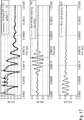
- the upper panel of Fig. 14 shows a diagram comprising a series of input values 1402, which may correspond to the series of input values 12 and a series of template values 1403, which may correspond to the template 13.
- the series of input values 1402 comprises a signal representing a ringing of an ultrasonic transceiver and an echo 1460 of an ultrasonic signal.
- the second panel comprises a difference between the series of input values 1402 and the series of template values 1403 determined without using the warping.
- the difference signal 1408 comprises a high amplitude peak 1480 which represents an artefact of the template subtraction.
- the lower panel of Fig. 14 shows a series of corrected input values 1407 as an example of the series of correct input values 17.
- the series of corrected input values 1407 comprises a residual noise signal 1450 and further comprises a signal representing an echo 1460.
- the residual noise signal 1450 may have a different, e.g. a higher frequency than the signal of interest 1460.
- Fig. 14 may illustrate an example of a DTW algorithm applied in presence of an echo. Spurious peaks in the blanking zone may be suppressed while the echo signal 1460 may remain unchanged, or may remain detectable in the corrected signal.
- the apparatus 10 is configured for applying a frequency filter to the corrected signal.
- the frequency filter is configured for transmitting a signal with a frequency within a range of ⁇ 50%, preferably ⁇ 20%, more preferably ⁇ 5% of a frequency of the transmitted ultrasonic signal 1220 and configured for attenuating a signal with a frequency outside the range.
- a residual noise signal for example the residual noise signal 1450
- a signal of interest for example the echo 1460
- the frequency filter may prevent a false detection of echo signal in case of a residual noise signal.
- the series of input values 12 and the series of template values 13 cover a timespan of a ringing of the transceiver 1210 after transmitting the ultrasonic signal 1220.
- the timespan may be 0 to 1 ms after transmitting the ultrasonic signal 1220.
- Fig. 15 shows a flow chart of a method 1500 for correcting an input signal 11 according to an embodiment.
- the method 1500 comprises a step 1510 of receiving the input signal 11, the received input signal 11 comprising a series of input values 12.
- the step 1520 comprises matching a series of template values 13 to the series of input values 12 by warping the series of template values 13 and the series of input values 12 relative to each other so as to assign one or more template values to one or more input values.
- the series of template values 13 represents an approximation of a noise signal that is expected to be comprised in the input signal 11.
- the method 1500 further comprises a step 1530 of obtaining a series of corrected input values 17 based on a mismatch between the input values and their respective assigned template values. Further, the step 1540 comprises providing a corrected signal 19 based on the series of corrected input values 17.
- the method 1500 provides the features, functionalities and advantages described with respect to the apparatus 10 for correcting an input signal 11.
- Fig. 16 shows a flow chart of a method 1600 for obtaining an information about a TOF of an ultrasonic signal according to an embodiment.
- the method 1600 may be implemented by the apparatus 1200.
- the method 1600 comprises a step 1699 of correcting the input signal 11.
- the step 1699 may be an implementation of the method 1500.
- the input signal 11 may represent a detected ultrasonic signal.
- the step 1699 may comprise splitting the detected ultrasonic signal 11 into intervals so as to obtain a series of input values 12 which may represent an interval of the detected ultrasonic signal 11 within which a ringing is to be expected.
- the splitting may also be referred to as signal windowing.
- the selective transformation may bring considerable advantages in the blanking zone, while maintaining unaltered the echo signal-to-noise ratio after or without the blanking zone, since not suppressed by adaptive mechanisms.
- the step 1699 comprises a step 1625, in which the series of input values 12 is matched to a series of template values 13.
- the warping may be selectively applied only to the first interval of the time series, leaving the remaining epochs of the recorded time series 11 untouched.
- the template 13 may represent an approximation of the ringing.
- the step 1625 may rely on a DTW algorithm.
- the step 1625 implements the steps 1520, 1530 of the method 1500.
- the step 1625 may provide a series of corrected input values 17.
- a patching operation may use the series of corrected input values 17 for patching the detected ultrasonic signal 11, so as to obtain the corrected or patched signal 19.
- a band pass filter 1651 for example a frequency filter is applied to the patched signal 19 so as to obtain a filtered signal 1652.
- a cross-correlation between the filtered signal 1652, e.g. a warped difference, and an echo template 1662 is determined, so as to obtain a correlated signal 1661.
- the echo template 1662 comprises information about a transmitted ultrasonic signal being a basis or an origin of an echo which may be comprised in the detected ultrasonic signal 11.
- the echo template 1662 is based on a form of the transmitted ultrasonic signal and/or may comprise information about a transfer function or response function of the transceiver or other hardware in the signal chain.
- a maximum of the correlated signal 1661 is determined based on a time gain compensation 1671.
- a detected maximum may represent a received echo, so that the information 1290 about a TOF of the ultrasonic signal may be estimated based on a position of the detected maximum on the time axis.
- the upper panel of Fig. 17 shows a diagram comprising a series of template values 1703 and a series of input values 1702, which may correspond to the series of template values 13 and the series of input values 12, respectively.
- the series of input values 1702 may represent a case of no echo in the blanking zone.
- the second panel of Fig. 17 shows a diagram comprising a cross correlated signal 1798.
- the cross-correlated signal 1798 may have been derived by a method similar to the method 1600, wherein the step 1625 is replaced by a simple blind subtraction.
- the cross-correlation 1798 of the blind difference may lead to a false echo detection.
- the lower panel of Fig. 17 shows an example of the cross-correlated signal 1661 which may have been derived as described with respect to Fig. 16 .
- a maximum or a local maximum of the cross-correlated signal 1661 occur in a region where no echo may be expected, for example due to actuation. Thus, no object may be detected based on the cross-correlated signal 1798
- the upper panel of Fig. 18 shows a diagram comprising a series of template values 1803 and a series of input values 1802, which may correspond to the series of template values 13 and the series of input values 12, respectively.
- the series of input values 1802 may represent a case of an overlapping echo in the blanking zone, for example the series of input values 1802 may comprise a signal representing an echo 1860.
- the second panel of Fig. 18 shows a cross-correlated signal 1898 which may have been derived based on a blind subtraction, similar to the cross-correlated signal 1798 of Fig. 17 .
- a maximum 1897 of the cross-correlated signal 1898 appears at a time value which is different from a time value of the echo 1860 in the upper panel.
- FIG. 18 shows a diagram comprising an example of the correlated signal 1661 which may have been derived as described with respect to Fig. 16 .
- a maximum 1862 of the cross-correlated signal 1661 is close to a position of the echo 1860 of the upper panel.
- the cross-correlation 1661 of the warped difference for example a series of corrected input values derived from the series of input values 1802 and the series of template values 1803, may lead to a more accurate detection of the echo 1860 compared to the cross-correlated signal 1898, although a signal to noise ratio of the cross correlated signal 1661 may be lower.
- Fig. 19 shows a method 1900 for obtaining an information 1290 about a TOF of an ultrasonic signal according to an embodiment.
- the method 1900 is based on the method 1600 comprising the indicated features of the method 1600.
- the step 1625 is replaced by a step 1925.
- Step 1925 comprises matching the series of input values 12 and the series of template values 13 and comprises obtaining the corrected template 76.
- the method 1900 comprises a subtraction 1947 of the corrected template 76 from the input signal 11.
- the corrected template may be zero-padded for subtracting it from the input signal 11.
- the warped template 76 may be zero-padded in order to reach the length of the received time series 11, which may constitute the corrected template 76.
- the subtraction 1947 results in a processed signal which may be similar to the patched signal 19.
- the described method 1900 may reach from signal windowing, for membrane ringing epoch identification, to TOF estimation for echo detection.
- a block 1991 may be referred to as Interval Selective DTW and may be responsible for signal windowing, cost function calculation and template warping.
- a following block 1992 may represent a proper Ringing subtraction. The subtraction may lead to a 'similarity fingerprint', which may be zero-padded to return the Corrected Template 76.
- the disclosed apparatuses 10, 1200 and methods 1500, 1600, 1900 may fulfill low-power requirements, for example of mobile applications. Ultrasonic usage in mobile devices is attractive for disparate applications such as range finding, presence detection, wind/temperature measurement, gesture classification. When considering single CMUT, the ringing subtraction problem may have to be taken into account.
- the disclosed apparatuses 10, 1200 and methods 1500, 1600, 1900 provide a low-cost methodology for effective ringing suppression for precise short-range measurements with ultrasonic transceivers.
- the concept may embed a DTW-based non-linear transformation for epochs-selective warping of a membrane reverberation artifact.
- the selectivity may be guaranteed by the a-priority knowledge of the localization and duration of the artifacts, as well as by the selection of appropriate boundary conditions.
- the concept may return a warped difference as similarity fingerprint, which may be used for ringing suppression in the real-time recorded signal. When the similarity is high, the subtraction may return its minimum realization, i.e. zeroing the warped difference.
- the subtraction may contain residuals which are assumed to be constituents of the echo and thus used for subsequent processing.
- the concept may implement a low-complexity always-on mechanism for template matching which may guarantee enhanced adaptability to diverse MEMS devices, e.g. revealing manufacturing tolerances, as well as adaptability for the same devices, which proved to be variable overtime e.g. due to temperature changes.
- the concept may enable a reduced calibration routine since the same template can be stored in each sensor, allowing mass-applications. Thus, the base template is adjusted automatically for each device.
- the matching of the template 13 to the series of input values 12 is based on a template-matching algorithm based on a Kalman filter.
- the implementation of the Kalman filter based matching may determine matching points, for example best matching points, between the reference ringing template, e.g. the template 13, and the real-time recorded data, e.g. the series of input values.
- the implementation of the Kalman filter based matching may comprise a prediction step which may be based on inference from a prior knowledge state, and may comprise an update step which may be based on a comparison between a prediction and a measurement, e.g. the input values.
- the prediction step is unbounded and the filter or the matching may be applied to the entire ultrasonic recording, e.g. the series of input values 12 may represent the entire range of the input signal 11.
- an apparatus 10 for correcting an input signal 11 is configured for: receiving the input signal 11, the received input signal 11 comprising a series of input values 12; matching a series of template values 13 to the series of input values 12 by warping the series of template values 13 and the series of input values 12 relatively to each other so as to assign one or more template values to one or more input values, wherein the series of template values 13 represents an approximation of a noise signal that is expected to be comprised in the input signal 11; obtaining a series of corrected input values 17 based on a mismatch between the input values and their respective assigned template values; providing a corrected signal 19 based on the series of corrected input values 17.
- matching the series of template values 13 to the series of input values 12 comprises assigning one or more template values to one or more input values so as to decrease a sum of absolute distances between the input values and their respective assigned template values.
- matching the series of template values 13 to the series of input values 12 comprises using a dynamic time warping algorithm for assigning the template values to the input values.
- the apparatus 10 is configured for obtaining a corrected template 76 and a series of warped input values 78 based on the matching of the series of template values 13 to the series of input values 12; and the apparatus 10 is configured for obtaining the series of corrected input values 17 based on a difference between the series of warped input values 78 and the corrected template 76.
- the apparatus 10 is configured for splitting the input signal 11 into a plurality of intervals comprising an interval of interest 1308, within which the noise signal is expected to occur, wherein the interval of interest 1308 comprises the series of input values 12, which is to be matched with the series of template values 13.
- the apparatus 10 is configured for patching the interval of interest 1308 of the input signal 11 using the series of corrected input values 17, so as to obtain the corrected signal 19.
- the input signal 1301 represents a time series of a measured value
- the series of template values 13 comprises a time series of a noise signal
- the series of input values 12 and the series of template values 13 cover an equal time span.
- the apparatus 10 is configured for identifying a part of the series of corrected input values 17 as a signal of interest, if the corrected input values of the part of the series of corrected input values 17 exceed a threshold value; and the apparatus 10 is configured for identifying a part of the series of corrected input values 17 as a residual noise signal, if the corrected input values of the part of the series of corrected input values 17 do not exceed the threshold value.
- the apparatus 10 is configured for applying a frequency filter to the series of corrected input values 17.
- the series of input values 12 and the series of template values 13 have equal lengths.
- an apparatus 1200 for obtaining an information 1290 about a time of flight of an ultrasonic signal comprises: a transceiver 1210, configured for transmitting the ultrasonic signal 1220 during a first time span, and configured for receiving an ultrasonic signal 1230 during a second time span, wherein the transceiver 1210 is configured for providing an input signal 11 comprising the received ultrasonic signal 1230 in a time series; the apparatus 10 for correcting an input signal according to any of the preceding embodiments, configured for receiving the input signal 11 and configured for providing the corrected signal 19; means 1240 for obtaining the information 1290 about the time of flight of the ultrasonic signal by evaluating the corrected signal 19.
- the apparatus 1200 is configured for applying a frequency filter to the corrected signal 19, wherein the frequency filter is configured for transmitting a signal with a frequency within a range of ⁇ 50 %, preferably ⁇ 20 %, more preferably ⁇ 5 % of a frequency of the transmitted ultrasonic signal 1220 and configured for attenuating a signal with a frequency outside of the range.
- the series of input values 12 and the series of template values 13 cover a time span of a ringing of the transceiver 1210 after transmitting the ultrasonic signal 1220.
- a method 1500 for correcting an input signal comprises: receiving 1510 the input signal 11, the received input signal 11 comprising a series of input values 12; matching 1520 a series of template values 13 to the series of input values 12 by warping the series of template values 13 and the series of input values 12 relatively to each other so as to assign one or more template values to one or more input values, wherein the series of template values 13 represents an approximation of a noise signal that is expected to be comprised in the input signal 11; obtaining 1530 a series of corrected input values 17 based on a mismatch between the input values and their respective assigned template values; providing 1540 a corrected signal 19 based on the series of corrected input values 17.
- a computer program implements the method of the preceding embodiment when being executed on a computer or signal processor.
- Some or all of the method steps may be executed by (or using) a hardware apparatus, like for example, a microprocessor, a programmable computer or an electronic circuit. In some embodiments, one or more of the most important method steps may be executed by such an apparatus.
- embodiments of the invention can be implemented in hardware or in software or at least partially in hardware or at least partially in software.
- the implementation can be performed using a digital storage medium, for example a floppy disk, a DVD, a Blu-Ray, a CD, a ROM, a PROM, an EPROM, an EEPROM or a FLASH memory, having electronically readable control signals stored thereon, which cooperate (or are capable of cooperating) with a programmable computer system such that the respective method is performed. Therefore, the digital storage medium may be computer readable.
- Some embodiments according to the invention comprise a data carrier having electronically readable control signals, which are capable of cooperating with a programmable computer system, such that one of the methods described herein is performed.
- embodiments of the present invention can be implemented as a computer program product with a program code, the program code being operative for performing one of the methods when the computer program product runs on a computer.
- the program code may for example be stored on a machine readable carrier.
- inventions comprise the computer program for performing one of the methods described herein, stored on a machine readable carrier.
- an embodiment of the inventive method is, therefore, a computer program having a program code for performing one of the methods described herein, when the computer program runs on a computer.
- a further embodiment of the inventive methods is, therefore, a data carrier (or a digital storage medium, or a computer-readable medium) comprising, recorded thereon, the computer program for performing one of the methods described herein.
- the data carrier, the digital storage medium or the recorded medium are typically tangible and/or non-transitory.
- a further embodiment of the inventive method is, therefore, a data stream or a sequence of signals representing the computer program for performing one of the methods described herein.
- the data stream or the sequence of signals may for example be configured to be transferred via a data communication connection, for example via the Internet.
- a further embodiment comprises a processing means, for example a computer, or a programmable logic device, configured to or adapted to perform one of the methods described herein.
- a processing means for example a computer, or a programmable logic device, configured to or adapted to perform one of the methods described herein.
- a further embodiment comprises a computer having installed thereon the computer program for performing one of the methods described herein.
- a further embodiment according to the invention comprises an apparatus or a system configured to transfer (for example, electronically or optically) a computer program for performing one of the methods described herein to a receiver.
- the receiver may, for example, be a computer, a mobile device, a memory device or the like.
- the apparatus or system may, for example, comprise a file server for transferring the computer program to the receiver.
- a programmable logic device for example a field programmable gate array
- a field programmable gate array may cooperate with a microprocessor in order to perform one of the methods described herein.
- the methods are preferably performed by any hardware apparatus.
- the apparatus described herein may be implemented using a hardware apparatus, or using a computer, or using a combination of a hardware apparatus and a computer.
- the methods described herein may be performed using a hardware apparatus, or using a computer, or using a combination of a hardware apparatus and a computer.
Priority Applications (2)
| Application Number | Priority Date | Filing Date | Title |
|---|---|---|---|
| EP20155343.5A EP3862782A1 (de) | 2020-02-04 | 2020-02-04 | Vorrichtung und verfahren zur korrektur eines eingangssignals |
| US17/144,913 US11942975B2 (en) | 2020-02-04 | 2021-01-08 | Apparatus and method for correcting an input signal |
Applications Claiming Priority (1)
| Application Number | Priority Date | Filing Date | Title |
|---|---|---|---|
| EP20155343.5A EP3862782A1 (de) | 2020-02-04 | 2020-02-04 | Vorrichtung und verfahren zur korrektur eines eingangssignals |
Publications (1)
| Publication Number | Publication Date |
|---|---|
| EP3862782A1 true EP3862782A1 (de) | 2021-08-11 |
Family
ID=69468411
Family Applications (1)
| Application Number | Title | Priority Date | Filing Date |
|---|---|---|---|
| EP20155343.5A Pending EP3862782A1 (de) | 2020-02-04 | 2020-02-04 | Vorrichtung und verfahren zur korrektur eines eingangssignals |
Country Status (2)
| Country | Link |
|---|---|
| US (1) | US11942975B2 (de) |
| EP (1) | EP3862782A1 (de) |
Families Citing this family (1)
| Publication number | Priority date | Publication date | Assignee | Title |
|---|---|---|---|---|
| DE102022116122A1 (de) | 2022-06-29 | 2024-01-04 | Valeo Schalter Und Sensoren Gmbh | Verfahren zum erkennen eines falsch-positiven echosignals |
Citations (2)
| Publication number | Priority date | Publication date | Assignee | Title |
|---|---|---|---|---|
| US5729193A (en) * | 1994-07-16 | 1998-03-17 | Kiekert Aktiengesellschaft | Method of monitoring a vehicle interior |
| WO2009051899A1 (en) * | 2007-10-17 | 2009-04-23 | Exxonmobil Upstream Research Company | Method to adapt a template dataset to a target dataset by using curvelet representations |
Family Cites Families (34)
| Publication number | Priority date | Publication date | Assignee | Title |
|---|---|---|---|---|
| US5487129A (en) * | 1991-08-01 | 1996-01-23 | The Dsp Group | Speech pattern matching in non-white noise |
| US6381569B1 (en) * | 1998-02-04 | 2002-04-30 | Qualcomm Incorporated | Noise-compensated speech recognition templates |
| US6466906B2 (en) * | 1999-01-06 | 2002-10-15 | Dspc Technologies Ltd. | Noise padding and normalization in dynamic time warping |
| US6870792B2 (en) * | 2000-04-04 | 2005-03-22 | Irobot Corporation | Sonar Scanner |
| US6876966B1 (en) * | 2000-10-16 | 2005-04-05 | Microsoft Corporation | Pattern recognition training method and apparatus using inserted noise followed by noise reduction |
| US7016833B2 (en) * | 2000-11-21 | 2006-03-21 | The Regents Of The University Of California | Speaker verification system using acoustic data and non-acoustic data |
| US6470047B1 (en) * | 2001-02-20 | 2002-10-22 | Comsys Communications Signal Processing Ltd. | Apparatus for and method of reducing interference in a communications receiver |
| US7039017B2 (en) * | 2001-12-28 | 2006-05-02 | Texas Instruments Incorporated | System and method for detecting and locating interferers in a wireless communication system |
| US7106868B2 (en) * | 2002-05-15 | 2006-09-12 | Siemens Vdo Automotive Inc. | Active noise control for vehicle door noise |
| US6805132B2 (en) * | 2002-08-06 | 2004-10-19 | Scimed Life Systems, Inc. | Performing ultrasound ranging in the presence of ultrasound interference |
| US8214012B2 (en) * | 2004-06-17 | 2012-07-03 | Psychology Software Tools, Inc. | Magnetic resonance imaging having patient video, microphone and motion tracking |
| US7477992B2 (en) * | 2005-02-18 | 2009-01-13 | Exxonmobil Upstream Research Company | Method for combining seismic data sets |
| KR20060124824A (ko) * | 2005-05-26 | 2006-12-06 | 주식회사 메디슨 | 초음파 스펙트럼 영상을 처리하는 방법 및 초음파 진단시스템 |
| US7333392B2 (en) * | 2005-09-19 | 2008-02-19 | Saudi Arabian Oil Company | Method for estimating and reconstructing seismic reflection signals |
| US8290100B2 (en) * | 2006-08-08 | 2012-10-16 | Qualcomm Incorporated | Interference detection and mitigation |
| EP1892908A1 (de) * | 2006-08-24 | 2008-02-27 | TTPCOM Limited | Empfänger und Verfahren zur Störungsunterdrückung |
| KR20120035074A (ko) | 2010-10-04 | 2012-04-13 | 한국전자통신연구원 | 부채널 분석을 위한 노이즈 모델을 이용한 파형 노이즈 제거 방법 및 이를 이용한 부채널 분석 장치 |
| US9178553B2 (en) * | 2012-01-31 | 2015-11-03 | Broadcom Corporation | Systems and methods for enhancing audio quality of FM receivers |
| US10424292B1 (en) * | 2013-03-14 | 2019-09-24 | Amazon Technologies, Inc. | System for recognizing and responding to environmental noises |
| DE102013019431A1 (de) * | 2013-11-20 | 2015-05-21 | Valeo Schalter Und Sensoren Gmbh | Verfahren zum Bestimmen des Signal-Rausch-Verhältnisses eines Zielechos eines von einem Ultraschallsensor eines Kraftfahrzeugs empfangenen Empfangssignals, Fahrerassistenzeinrichtung und Kraftfahrzeug |
| JP6388957B2 (ja) * | 2014-04-11 | 2018-09-12 | エスゼット ディージェイアイ テクノロジー カンパニー リミテッドSz Dji Technology Co.,Ltd | 近接感知システムおよび方法 |
| KR102339517B1 (ko) * | 2015-01-27 | 2021-12-16 | 현대모비스 주식회사 | 차량용 초음파 감지 장치 및 그 방법 |
| US11035937B2 (en) * | 2015-12-28 | 2021-06-15 | Leddartech Inc. | Intrinsic static noise characterization and removal |
| US11630518B2 (en) * | 2018-03-19 | 2023-04-18 | King Abdullah University Of Science And Technology | Ultrasound based air-writing system and method |
| WO2019192981A1 (en) * | 2018-04-02 | 2019-10-10 | Koninklijke Philips N.V. | Noise reduction for ultrasound operations |
| DE102018206700A1 (de) * | 2018-05-02 | 2019-11-07 | Robert Bosch Gmbh | Verfahren und Vorrichtung zum Erkennen eines in einem Empfangssignal eines Ultraschallsensors abgebildeten Geräuschs |
| US11644555B2 (en) * | 2018-07-27 | 2023-05-09 | Texas Instruments Incorporated | Threshold generation for coded ultrasonic sensing |
| JP2020085506A (ja) * | 2018-11-16 | 2020-06-04 | アイシン精機株式会社 | 距離検出装置および物体検出装置 |
| KR20200067629A (ko) * | 2018-12-04 | 2020-06-12 | 삼성전자주식회사 | 레이더 데이터를 처리하는 장치 및 방법 |
| CN114128321A (zh) * | 2019-03-01 | 2022-03-01 | 弗克拜德技术公共有限责任公司 | 可靠的检测车辆内智能手机的方法和系统 |
| US10725588B2 (en) * | 2019-03-25 | 2020-07-28 | Intel Corporation | Methods and apparatus to detect proximity of objects to computing devices using near ultrasonic sound waves |
| JP2021042077A (ja) * | 2019-09-03 | 2021-03-18 | コニカミノルタ株式会社 | 搬送装置 |
| US11175402B2 (en) * | 2019-11-25 | 2021-11-16 | Texas Instruments Incorporated | Time-varying template for improved short-distance performance in coded ultrasonic ranging |
| US11025324B1 (en) * | 2020-04-15 | 2021-06-01 | Cirrus Logic, Inc. | Initialization of adaptive blocking matrix filters in a beamforming array using a priori information |
-
2020
- 2020-02-04 EP EP20155343.5A patent/EP3862782A1/de active Pending
-
2021
- 2021-01-08 US US17/144,913 patent/US11942975B2/en active Active
Patent Citations (2)
| Publication number | Priority date | Publication date | Assignee | Title |
|---|---|---|---|---|
| US5729193A (en) * | 1994-07-16 | 1998-03-17 | Kiekert Aktiengesellschaft | Method of monitoring a vehicle interior |
| WO2009051899A1 (en) * | 2007-10-17 | 2009-04-23 | Exxonmobil Upstream Research Company | Method to adapt a template dataset to a target dataset by using curvelet representations |
Non-Patent Citations (3)
| Title |
|---|
| ANONYMOUS: "Dynamic time warping - Wikipedia", 8 September 2018 (2018-09-08), XP055658258, Retrieved from the Internet <URL:https://en.wikipedia.org/w/index.php?title=Dynamic_time_warping&oldid=858621158> [retrieved on 20200115] * |
| LAGLER DANIEL ET AL: "A Single Ultrasonic Transducer Fast and Robust Short-Range Distance Measurement Method", 2019 IEEE INTERNATIONAL ULTRASONICS SYMPOSIUM (IUS), IEEE, 6 October 2019 (2019-10-06), pages 2533 - 2536, XP033670962, DOI: 10.1109/ULTSYM.2019.8925554 * |
| SUBODH, P. S. ET AL.: "A Novel Method for Reverberation Cancellation in Single Ultrasonic Transducer based Measurement System", DIGITAL SIGNAL PROCESSING, NDE2015, 2015 |
Also Published As
| Publication number | Publication date |
|---|---|
| US20210242891A1 (en) | 2021-08-05 |
| US11942975B2 (en) | 2024-03-26 |
Similar Documents
| Publication | Publication Date | Title |
|---|---|---|
| Khan et al. | Multi‐component instantaneous frequency estimation using locally adaptive directional time frequency distributions | |
| KR101199169B1 (ko) | 타깃물체 감지 방법 및 레이더 장치 | |
| EP1718988B1 (de) | Hf-kanalkalibration für nichtlineare fm-signalformen | |
| JP6188640B2 (ja) | 壁の背後のシーンにおけるターゲットを検出するシステム | |
| JP5711465B2 (ja) | ステップ周波数技術によるアンビギュアスピークを抑圧するためのシステム及び方法 | |
| US8391344B2 (en) | Transceiving device of pulse signal | |
| CN106164700B (zh) | 用于识别在超声传感器的邻近区域中的对象的方法 | |
| US11942975B2 (en) | Apparatus and method for correcting an input signal | |
| KR102466201B1 (ko) | 방법, 컴퓨터 프로그램 제품, 장치 및 주파수 변조 연속파 레이더 시스템 | |
| US20120092210A1 (en) | Method for Processing an Echo Amplitude Profile Generated by a Pulse-Echo Ranging System | |
| US20150092518A1 (en) | Apparatus and method for removing noise of ultrasonic system | |
| US10591582B1 (en) | Co-notch and independent windowing to mitigate interference in SAR-based imagery | |
| JP5708294B2 (ja) | 信号検出装置、信号検出方法及び信号検出プログラム | |
| Tian et al. | Statistical analysis of split spectrum processing for multiple target detection | |
| US10288726B2 (en) | Impulse noise detection and removal for radar and communication systems | |
| JP6970307B2 (ja) | レーダ信号を補正する方法および装置ならびにレーダ装置 | |
| Shpigler et al. | Detection of overlapping ultrasonic echoes with deep neural networks | |
| US20230057115A1 (en) | Signal detection method and apparatus, and radar system | |
| US20120056779A1 (en) | Method and Apparatus for Determination of a Doppler Frequency Shift Resulting from the Doppler Effect | |
| CN116449328A (zh) | 基于时频分析特征融合的雷达工作模式识别方法及系统 | |
| JPH09269370A (ja) | 探知画像データ処理方法、物体探知装置、超音波診断装置、およびレーダ | |
| Tesei et al. | The asymmetric generalized gaussian function: A new hos-based model for generic noise pdfs | |
| US11835649B2 (en) | Method and apparatus for radar signal processing using convolutional neural network | |
| CN111722229A (zh) | 物体检测装置 | |
| JP2014202525A (ja) | 超音波探傷方法および超音波探傷装置 |
Legal Events
| Date | Code | Title | Description |
|---|---|---|---|
| PUAI | Public reference made under article 153(3) epc to a published international application that has entered the european phase |
Free format text: ORIGINAL CODE: 0009012 |
|
| STAA | Information on the status of an ep patent application or granted ep patent |
Free format text: STATUS: THE APPLICATION HAS BEEN PUBLISHED |
|
| AK | Designated contracting states |
Kind code of ref document: A1 Designated state(s): AL AT BE BG CH CY CZ DE DK EE ES FI FR GB GR HR HU IE IS IT LI LT LU LV MC MK MT NL NO PL PT RO RS SE SI SK SM TR |
|
| STAA | Information on the status of an ep patent application or granted ep patent |
Free format text: STATUS: REQUEST FOR EXAMINATION WAS MADE |
|
| 17P | Request for examination filed |
Effective date: 20211207 |
|
| RBV | Designated contracting states (corrected) |
Designated state(s): AL AT BE BG CH CY CZ DE DK EE ES FI FR GB GR HR HU IE IS IT LI LT LU LV MC MK MT NL NO PL PT RO RS SE SI SK SM TR |
|
| STAA | Information on the status of an ep patent application or granted ep patent |
Free format text: STATUS: EXAMINATION IS IN PROGRESS |
|
| 17Q | First examination report despatched |
Effective date: 20231006 |