EP3862243A1 - Paroi de véhicule, de préférence ferroviaire, procédé de fabrication et véhicule associés - Google Patents
Paroi de véhicule, de préférence ferroviaire, procédé de fabrication et véhicule associés Download PDFInfo
- Publication number
- EP3862243A1 EP3862243A1 EP21155503.2A EP21155503A EP3862243A1 EP 3862243 A1 EP3862243 A1 EP 3862243A1 EP 21155503 A EP21155503 A EP 21155503A EP 3862243 A1 EP3862243 A1 EP 3862243A1
- Authority
- EP
- European Patent Office
- Prior art keywords
- vehicle
- skin
- wall
- structural
- reinforcements
- Prior art date
- Legal status (The legal status is an assumption and is not a legal conclusion. Google has not performed a legal analysis and makes no representation as to the accuracy of the status listed.)
- Granted
Links
Images


Classifications
-
- B—PERFORMING OPERATIONS; TRANSPORTING
- B61—RAILWAYS
- B61D—BODY DETAILS OR KINDS OF RAILWAY VEHICLES
- B61D17/00—Construction details of vehicle bodies
- B61D17/04—Construction details of vehicle bodies with bodies of metal; with composite, e.g. metal and wood body structures
- B61D17/08—Sides
-
- B—PERFORMING OPERATIONS; TRANSPORTING
- B61—RAILWAYS
- B61D—BODY DETAILS OR KINDS OF RAILWAY VEHICLES
- B61D17/00—Construction details of vehicle bodies
- B61D17/04—Construction details of vehicle bodies with bodies of metal; with composite, e.g. metal and wood body structures
-
- Y—GENERAL TAGGING OF NEW TECHNOLOGICAL DEVELOPMENTS; GENERAL TAGGING OF CROSS-SECTIONAL TECHNOLOGIES SPANNING OVER SEVERAL SECTIONS OF THE IPC; TECHNICAL SUBJECTS COVERED BY FORMER USPC CROSS-REFERENCE ART COLLECTIONS [XRACs] AND DIGESTS
- Y02—TECHNOLOGIES OR APPLICATIONS FOR MITIGATION OR ADAPTATION AGAINST CLIMATE CHANGE
- Y02T—CLIMATE CHANGE MITIGATION TECHNOLOGIES RELATED TO TRANSPORTATION
- Y02T30/00—Transportation of goods or passengers via railways, e.g. energy recovery or reducing air resistance
Definitions
- the walls of a vehicle in particular of a rail vehicle, in addition to ensuring the definition of an interior of a vehicle with respect to its exterior, have a structural role for the vehicle.
- the vehicle walls must in particular ensure sufficient rigidity of the vehicle.
- An object of this invention is to provide a vehicle wall whose mass is low and whose manufacture is simple.
- the invention relates to a vehicle wall as defined above in which the vehicle skin is a steel sheet, the vehicle skin being fixed to at least one structural reinforcement by resistance welding and / or by laser welding, with or without the addition of a structural adhesive.
- a vehicle wall in which the elements are joined by resistance welding and / or by laser welding, with or without the addition of a structural adhesive ensures easy manufacture of the wall, such joining methods ensuring low deformation elements constituting the vehicle wall and allowing the omission of a step of straightening the skin.
- the use of the skin in combination with stamped steel elements also ensures the lightness of the wall.
- the invention also relates to a vehicle, preferably a railway vehicle, comprising a vehicle wall as mentioned above.
- the elevation direction Z is defined according to the height of the vehicle and corresponds for example to the vertical direction when the vehicle is on a horizontal track.
- the longitudinal direction X corresponds to the front-rear direction of the vehicle and the transverse direction Y corresponds to the direction along the width of the vehicle.
- a vehicle 10 comprising a vehicle wall 12 is shown in figure 1 .
- the vehicle 10 is preferably a rail vehicle.
- the vehicle 10 is for example a railway vehicle such as a metro or a tram.
- the vehicle 10 is a railcar, a car of a railcar or any car of a rail vehicle for transporting passengers or goods.
- the vehicle is a road vehicle, such as a bus or a coach.
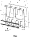
- the wall 12 comprises at least one assembly 14 of structural reinforcements 15 and a skin 16 of the vehicle.
- the wall preferably comprises a protective layer 17 ( figure 3 ).
- the wall 12 comprises welds 18 and / or a structural adhesive layer 20 connecting the skin 16 to the assembly 14 of structural reinforcements 15.
- the wall 12 preferably comprises at least one spar 21.
- the wall 12 is understood between, and defines, an interior 22 of the vehicle 10 and an exterior 23 of the vehicle.
- the assembly 14 of structural reinforcements 15 preferably comprises a plurality of structural reinforcements 15.
- the wall 12 preferably comprises between four and fifteen structural reinforcements 15.
- Each structural reinforcement 15 includes a stamped steel element 24.
- Each structural reinforcement 15 is preferably covered with the protective layer 17.
- the whole of each structural reinforcement is in particular covered with the protective layer 17.
- the stamped steel member 24 is preferably formed from a steel blank which has been stamped.
- the pressed steel element 24 comprises an inner face 25 and an outer face 26.
- the distance between the inner face 25 and the outer face 26 representing the thickness of the element 24 is between 1 mm and 5 mm.
- the pressed steel member 24 is preferably formed from very high yield strength steel.
- the elastic limit of the steel forming the element 24 of pressed steel is for example greater than 450 MPa.
- the pressed steel element 24 is preferably a hollow body.
- the pressed steel element 24 is then in the form of a half-shell and / or has an open cross section.
- the pressed steel element 24 comprises in particular a hollow region 28 defining an interior volume 29.
- the hollow region 28 preferably comprises a bottom 28F, defining a bottom plane, and side walls 28L extending in a plane secant to the bottom. background shot.
- the stamped steel element 24 comprises an outline 30 corresponding to the edge of the stamped blank, and an edge 31, also called a flange, connected to the hollow region 28 and extending around the hollow region 28, between the hollow region 28 and the outline 30.
- the interior volume 29 extends in particular in the hollow region 28, between the bottom and the edge 31.
- the depth PC of the hollow region 28, also called the thickness of the interior volume 29, is for example between 150 mm and 200 mm.
- the width LB of the border 31, measured from its junction with the hollow region 28 and the contour 30 is for example less than 50 mm.
- the edge 31 comprises a multiplicity of sections, all of these sections not surrounding the whole of the hollow region 28.
- a periphery of the hollow region 28 then comprises at least two regions of junction with the edge. 31 and at least two sections of the contour 30.
- the structural reinforcement 15 is for example in the form of a beam with an Omega profile.
- the border 31 comprises a single section surrounding the whole of the hollow region 28.
- the periphery of the hollow region 28 then only consists of a single region of junction with the border 31.
- the structural reinforcements 15 forming the assembly 14 of structural reinforcements 15 are for example connected to one another.
- the structural reinforcements 15 forming the assembly 14 of structural reinforcements 15 are fixed together, for example by means of a weld bead extending between the contour 30 of two adjacent structural reinforcements 15.
- the structural reinforcements 15, or at least part of the structural reinforcements 15, have a general L or C or T shape, i.e. they define a corner or a non-linear junction of the assembly 14 reinforcements.
- the assembly 14 defines for example an opening such as a window in the wall 12.
- the structural reinforcements 15 extend in particular along a non-rectilinear axis, their shape then differing from that of a beam.
- Each spar 21 preferably extends in the longitudinal direction X.
- Each spar 21 is for example a section, preferably formed of aluminum.
- Each spar 21 is for example connected to at least two structural reinforcements 15. Each spar 21 is preferably fixed to the inner face 25 of at least two structural reinforcements 15. Each spar 21 is for example glued and / or riveted to the face. interior 25 of at least two structural reinforcements 15. Each spar 21 is for example adapted to maintain elements of comfort in the vehicle 10, such as for example a table and / or a seat.
- the skin 16 of vehicle 10 is a steel sheet.
- the elastic limit of the steel forming the skin 16 is for example greater than 450 MPa.
- the skin 16 is fixed to at least one structural reinforcement 15 by resistance welding and / or by laser welding, with or without the addition of structural adhesive.
- the skin 16 is preferably attached to each of the structural reinforcements 15 by resistance welding and / or by laser welding, with or without the addition of structural adhesive.
- the skin 16 is preferably fixed to the exterior face 26 of the structural reinforcement (s) 15.
- the skin 16 is attached to the exterior face 26 in the region of the edge 31.
- the skin 16 closes the hollow region 28 of each structural reinforcement 15.
- Skin 16 is preferably covered with protective layer 17. In particular, all of skin 16 is covered with protective layer 17.
- the protective layer 17 comprises a layer of paint deposited by cataphoresis.
- the protective layer 17 is suitable for protecting metallic elements, such as the structural reinforcements 15, the skin 16 and / or the longitudinal members 21.
- the thickness of the protective layer 17 is preferably between 20 ⁇ m and 30 ⁇ m
- the weld 18 is preferably a resistance weld. Alternatively, the weld is a laser weld. Each weld 18 is placed between one of the structural reinforcements 15 and the skin 16. Each weld 18 is in particular placed between the edge 31 of a structural reinforcement 15 and the skin 16.
- the weld 18 secures the structural reinforcement 15 and the skin 16.
- the weld 18 comprises for example a mixture of the materials of the structural reinforcement 15 and of the skin 16 which, following their fusion and their solidification, secures the structural reinforcement 15. and skin 16.
- the structural adhesive 20 is placed between one of the structural reinforcements 15 and the skin 16.
- the structural adhesive 20 is in particular placed between the edge 31 of a structural reinforcement 15 and the skin 16.
- the structural adhesive 20 is for example formed by a liquid which, after application between the structural reinforcement 15 and the skin 16, solidifies and secures the structural reinforcement 15 and the skin 16.
- the structural adhesive 20 is for example an epoxy resin.
- the wall 12 comprises a waterproof bead 32.
- the waterproof bead 32 is for example a bead of mastic.
- the waterproof bead 32 extends between the skin 16 of the vehicle 10 and at least one structural reinforcement 15.
- the waterproof bead 32 extends for example between the edge 31 and the skin 16.
- the waterproof bead 32 is in particular suitable for preventing the infiltration of fluid, preferably liquid, from the interior 22 and / or from the exterior 23 towards the interior volume 29.
- the wall 12 of the vehicle 10 is covered with a layer of paint.
- the paint layer spreads for example directly on the assembly 14 of structural reinforcements 15 and / or on the skin 16.
- the paint layer extends over the protective layer 17.
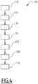
- a method 100 for manufacturing a vehicle wall 12 as described above will now be presented.
- a steel blank is provided for each of the structural reinforcements 15 and a vehicle skin 16 10 is provided.
- a stamping step 120 takes place following the supply step 110.
- each of the blanks provided above is stamped, forming a structural reinforcement 15.
- Each of the blanks is for example stamped. using a stamping press.
- each blank, during the stamping step 120 is deformed by the stamping press so as to form a structural reinforcement 15.
- the step advantageously comprises a sub-finishing step during which the stamped part is cut. , preferably using a laser cutting device, advantageously with five axes, in order to form the structural reinforcement 15.
- the laser cutting device cuts the contours 30 of the structural reinforcement.
- the laser cutter optionally cuts at least one opening in the structural reinforcement 15.
- the skin 16 is cut during an optional laser cutting step 130.
- the skin is for example cut using a laser beam.
- the laser cutting step 130 is followed by the fixing of each of the structural reinforcements 15 on the vehicle skin 16 during a fixing step 140.
- each of the structural reinforcements 15 are fixed to the vehicle skin 16 by resistance welding and / or by laser welding, with or without the addition of a structural adhesive 20, to form the wall 12 vehicle.
- a layer of structural adhesive 20 is for example applied between each of the structural reinforcements 15 and the skin 16 and / or a weld 18 by resistance and / or by laser welding is formed between each of the structural reinforcements 15 and the skin 16 for securing each of the structural reinforcements 15 and the skin.
- the structural reinforcements 15 are for example joined together by resistance welding and / or by MAG welding before or after the fixing step 140.
- the wall 12 is preferably sealed during a sealing step 150.
- sealing step 150 an interface between the vehicle skin 16 and at least one structural reinforcement 15 is sealed by placing a waterproof bead 32, such as for example a mastic seal.
- the protective layer 17 deposited by cataphoresis is preferably formed during a cataphoresis step 160.
- the cataphoresis step 160 is for example carried out before the sealing step 150.
- cataphoresis is performed on the vehicle wall 12.
- sealing step 160 is immersed in a bath of water-soluble paint.
- the paint present in the water-soluble paint bath is then deposited on the wall formed following the fixing step 140 and / or the sealing step 150 by means of an electric current between said wall acting as a cathode, and an anode submerged in the bath.
- the vehicle wall 12 formed following the fixing step 140 is preferably painted during a painting step 170.
- the painting step 170 is not preceded by a skin straightening or preparation step before painting.
- each of the structural reinforcements 15 on the skin 16 by resistance welding and / or by laser welding, with or without the addition of a structural adhesive 20, ensures that the skin is not deformed in the vicinity of the weld 18. and structural glue 20 while providing tension to the skin 16 thus eliminating irregular deformations of the skin and allowing the painting step 170 to be carried out without a skin straightening or preparation step before painting. In other words, it is not necessary to perform an operation for straightening the skin 16 before the cataphoresis, priming and finishing painting operations.
- the use of the skin in combination of stamped steel elements also ensures the lightness of the wall by the presence of structuring hollow bodies.
- the joining by resistance welding and / or by laser welding, with or without the addition of a structural adhesive 20, is particularly advantageous and allows in particular the elimination of a step of straightening the skin or of preparation before painting.
- the wall 12 comprising the structural reinforcements 15 as previously described is moreover particularly light while maintaining high rigidity.
- stamped steel elements 24 formed from steel with very high elastic limit allows the use of stamped elements, the production of which is rapid, while having elements of high structural performance ensuring in particular good wall rigidity. 12.
- the protective layer 17 comprising a layer of paint deposited by cataphoresis is moreover particularly advantageous for ensuring the strength of the vehicle wall 12 by in particular protecting the entire wall 12 from oxidation.
- a wall 12 comprising a multiplicity of structural reinforcements 14 is moreover particularly advantageous for facilitating the manufacture of the wall 12 while adapting the shape of the wall 12 to improve its structural performance.
- the laser cutting of the skin 16 ensures precise and rapid cutting of the skin 16 while limiting its deformation.
- the sealing step 150 prevents in particular the infiltration of water into the wall 12 produced and therefore ensures improved longevity of the wall.
- the painting step 170 without skin straightening or preparation before painting facilitates the fabrication of the vehicle wall 12.
Landscapes
- Engineering & Computer Science (AREA)
- Life Sciences & Earth Sciences (AREA)
- Wood Science & Technology (AREA)
- Mechanical Engineering (AREA)
- Body Structure For Vehicles (AREA)
- Laser Beam Processing (AREA)
- Application Of Or Painting With Fluid Materials (AREA)
Abstract
- au moins un ensemble (14) de renforts structurels (15), chaque renfort structurel (15) comprenant un élément en acier embouti (24) ; et
- une peau (16) de véhicule.
Description
- La présente invention concerne les parois de véhicule, de préférence de véhicule ferroviaire, comprenant :
- au moins un ensemble de renforts structurels, chaque renfort structurel comprenant un élément en acier embouti ; et
- une peau de véhicule.
- Les parois de véhicule, notamment de véhicule ferroviaire, en plus d'assurer la définition d'un intérieur d'un véhicule par rapport à son extérieur, ont un rôle structurel pour le véhicule. Les parois de véhicule doivent notamment assurer une rigidité suffisante du véhicule.
- De telles parois étant visibles depuis l'extérieur du véhicule, il est souhaité que de telles parois aient un aspect avantageux et soient par exemple dépourvues de déformations irrégulières. Ceci nécessite notamment le redressage d'éléments de la paroi lors ou avant le montage de la paroi sur le véhicule.
- Par ailleurs et comme les parois ont un rôle structurel, il est connu d'utiliser des parois d'épaisseur élevée dont la masse est élevée.
- De telles parois ne sont alors pas entièrement satisfaisantes puisqu'elles génèrent des coûts d'opération et de fabrication élevés du véhicule.
- Un but de cette invention est de proposer une paroi de véhicule dont la masse est faible et dont la fabrication est simple.
- A cet effet, l'invention a pour objet une paroi de véhicule telle que définie ci-dessus dans laquelle la peau de véhicule est une feuille en acier, la peau de véhicule étant fixée à au moins un renfort structurel par soudage par résistance et/ou par soudage laser, avec ou sans l'apport d'une colle structurelle.
- Une paroi de véhicule dans laquelle les éléments sont solidarisés par soudage par résistance et/ou par soudage laser, avec ou sans l'apport d'une colle structurelle, assure une fabrication facile de la paroi, de telles méthodes de solidarisation assurant une faible déformation des éléments constituant la paroi de véhicule et permettant l'omission d'une étape de redressement de la peau. L'utilisation de la peau en combinaison d'éléments en acier emboutis assure par ailleurs la légèreté de la paroi.
- Selon d'autres aspects avantageux de l'invention, la paroi de véhicule comprend l'une ou plusieurs des caractéristiques suivantes, prises isolément ou suivant toutes combinaisons techniquement possibles :
- l'élément en acier embouti est un corps creux en acier à très haute limite élastique, la limite élastique de l'acier étant supérieure à 450 MPa ;
- la paroi comprend une couche de protection, chaque renfort structurel et la peau de véhicule étant couverts de la couche de protection, la couche de protection comprenant une couche de peinture déposée par cataphorèse ; et
- la paroi comprend entre quatre et quinze renforts structurels et dans lequel la peau est fixée à chacun des renforts structurels par soudage par résistance et/ou par soudage laser, avec ou sans l'apport d'une colle structurelle.
- L'invention concerne en outre un procédé de fabrication d'une paroi de véhicule, la paroi étant telle que précité, le procédé comprenant les étapes suivantes :
- fourniture d'un flan en acier pour chacun des renforts structurels et d'une peau de véhicule ;
- emboutissage de chacun des flans en formant un renfort structurel ; et
- fixation de chacun des renforts structurels sur la peau de véhicule par soudage par résistance et/ou par soudage laser, avec ou sans l'apport d'une colle structurelle pour former la paroi de véhicule.
- Selon d'autres aspects avantageux de l'invention, le procédé de fabrication d'une paroi de véhicule comprend l'une ou plusieurs des caractéristiques suivantes, prises isolément ou suivant toute combinaisons techniquement possibles :
- le procédé comprend une étape de découpe laser de la peau de véhicule avant la fixation de chacun des renforts structurels sur la peau de véhicule ;
- le procédé comprend une étape d'étanchéification d'une interface entre la peau de véhicule et au moins un renfort structurel par mise en place d'un cordon étanche à l'interface entre la peau de véhicule et l'au moins un renfort structurel
- le procédé comprend une étape de cataphorèse de la paroi de véhicule formée à la suite de l'étape de fixation de chacun des renforts structurels sur la peau de véhicule.
- le procédé comprend une étape de peinture de la paroi de véhicule formée à la suite de l'étape de fixation de la peau sur chacun des renforts structurels, l'étape de peinture de la paroi de véhicule n'étant pas précédée d'une étape de redressage de la peau de véhicule ou de préparation avant la peinture.
- L'invention concerne par ailleurs un véhicule, de préférence ferroviaire, comprenant une paroi de véhicule telle que précitée.
- Ces caractéristiques et avantages de l'invention apparaitront plus clairement à la lecture de la description qui va suivre, donnée uniquement à titre d'exemple non limitatif, et faite en référence aux dessins annexés sur lesquels :
- [
Fig 1 ] lafigure 1 est une représentation schématique d'un véhicule, notamment d'un véhicule ferroviaire, comprenant une paroi de véhicule selon l'invention ; - [
Fig 2 ] lafigure 2 est une représentation schématique éclatée, selon un axe latéral d'un véhicule, de la paroi de véhicule de lafigure 1 ; - [
Fig 3 ] lafigure 3 est une vue en coupe perpendiculaire à un axe longitudinal du véhicule de la paroi de lafigure 1 ; et - [
Fig 4 ] lafigure 4 est un organigramme du procédé de fabrication d'une paroi de véhicule desfigures 1 à 3 . - Dans la description qui suit, on considère une base orthonormée directe (X, Y, Z). La direction d'élévation Z est définie selon la hauteur du véhicule et correspond par exemple à la direction verticale lorsque le véhicule est sur une voie horizontale. La direction longitudinale X correspond à la direction avant-arrière du véhicule et la direction transversale Y correspond à la direction selon la largeur du véhicule.
- Les termes « supérieur » et « inférieur » ainsi que « haut » et « bas » sont définis par rapport à la direction d'élévation Z. Les termes « gauche » et « droite » sont définis par rapport à la direction transversale Y dans le sens normal de circulation du véhicule.
- Les termes « intérieur » et « extérieur » sont définis en référence à l'intérieur et l'extérieur du véhicule.
- Un véhicule 10 comprenant une paroi de véhicule 12 est représenté en
figure 1 . - Le véhicule 10 est de préférence un véhicule ferroviaire. Le véhicule 10 est par exemple un véhicule ferroviaire tel un métro ou un tramway. En variante, le véhicule 10 est une automotrice, une voiture d'une automotrice ou toute voiture d'un véhicule ferroviaire de transport de passager ou de marchandise.
- En variante, le véhicule est un véhicule routier, tel qu'un bus ou un car.
- La paroi 12 comprend au moins un ensemble 14 de renforts structurels 15 et une peau 16 de véhicule. La paroi comprend de préférence une couche de protection 17 (
figure 3 ). - La paroi 12 comprend des soudures 18 et/ou une couche de colle structurelle 20 connectant la peau 16 à l'ensemble 14 de renforts structurels 15. La paroi 12 comprend de préférence au moins un longeron 21.
- La paroi 12 s'entend entre, et définit, un intérieur 22 de véhicule 10 et un extérieur 23 de véhicule.
- L'ensemble 14 de renforts structurels 15 comprend de préférence une pluralité de renforts structurels 15. En particulier, la paroi 12 comprend de préférence entre quatre et quinze renforts structurels 15.
- Chaque renfort structurel 15 comprend un élément 24 en acier embouti.
- Chaque renfort structurel 15 est de préférence couvert de la couche de protection 17. La totalité de chaque renfort structurel est en particulier couvert de la couche de protection 17.
- L'élément 24 en acier embouti est de préférence formé à partir d'un flan en acier ayant été embouti.
- L'élément 24 en acier embouti comprend une face intérieure 25 et une face extérieure 26.
- La distance entre la face intérieure 25 et la face extérieure 26 représentant l'épaisseur de l'élément 24 est comprise entre 1 mm et 5 mm.
- L'élément 24 en acier embouti est de préférence formé en acier à très haute limite élastique. La limite élastique de l'acier formant l'élément 24 en acier embouti est par exemple supérieure à 450 MPa.
- L'élément 24 en acier embouti est de préférence un corps creux. L'élément 24 en acier embouti est alors en forme de demi coquille et/ou a une section transversale ouverte.
- L'élément 24 en acier embouti comprend en particulier une région creuse 28 définissant un volume intérieur 29. La région creuse 28 comprend de préférence un fond 28F, définissant un plan de fond, et des parois latérales 28L s'étendant selon un plan sécant au plan de fond.
- L'élément 24 en acier embouti comprend un contour 30 correspondant au bord du flan embouti, et une bordure 31, aussi appelée bride, connectée à la région creuse 28 et s'étendant autour de la région creuse 28, entre la région creuse 28 et le contour 30.
- Le volume intérieur 29 s'étend en particulier dans la région creuse 28, entre le fond et la bordure 31.
- La profondeur PC de la région creuse 28, aussi appelée épaisseur du volume intérieur 29, est par exemple comprise entre 150 mm et 200 mm.
- La largeur LB de la bordure 31, mesurée depuis sa jonction avec la région creuse 28 et le contour 30 est par exemple inférieure à 50 mm.
- Selon une variante particulière, la bordure 31 comprend une multiplicité de tronçons, l'ensemble de ces tronçons n'entourant pas la totalité de la région creuse 28. Une périphérie de la région creuse 28 comprend alors au moins deux régions de jonction avec la bordure 31 et au moins deux sections du contour 30. Dans cette variante particulière, le renfort structurel 15 est par exemple en forme de poutre à profil en Oméga.
- Selon une variante alternative, la bordure 31 comprend un unique tronçon entourant la totalité de la région creuse 28. La périphérie de la région creuse 28 ne consiste alors qu'en une unique région de jonction avec la bordure 31.
- Les renforts structurels 15 formant l'ensemble 14 de renforts structurels 15 sont par exemple connectés entre eux. En particulier, les renforts structurels 15 formant l'ensemble 14 de renforts structurels 15 sont fixés entre eux, par exemple à l'aide d'un cordon de soudure s'étendant entre le contour 30 de deux renforts structurels 15 adjacents.
- Les renforts structurels 15, ou au moins une partie des renforts structurels 15, ont une forme générale de L ou de C ou de T, c'est-à-dire ils définissent un coin ou une jonction non-linéaire de l'ensemble 14 de renforts. L'ensemble 14 définit par exemple une ouverture telle une fenêtre de la paroi 12. Les renforts structurels 15 s'étendent en particulier selon un axe non-rectiligne, leur forme différant alors d'une forme de poutre.
- Chaque longeron 21 s'étend de préférence selon la direction longitudinale X. Chaque longeron 21 est par exemple un profilé, de préférence formé en aluminium.
- Chaque longeron 21 est par exemple connecté à au moins deux renforts structurels 15. Chaque longeron 21 est de préférence fixé à la face intérieure 25 d'au moins deux renforts structurels 15. Chaque longeron 21 est par exemple collé et/ou riveté à la face intérieure 25 d'au moins deux renforts structurels 15. Chaque longeron 21 est par exemple adapté pour maintenir des éléments de confort dans le véhicule 10, tels par exemple une table et/ou un siège.
- La peau 16 de véhicule 10 est une feuille en acier. La limite élastique de l'acier formant la peau 16 est par exemple supérieure 450 MPa.
- La peau 16 est fixée à au moins un renfort structurel 15 par soudage par résistance et/ou par soudage laser, avec ou sans apport de colle structurelle. La peau 16 est de préférence fixée à chacun des renforts structurels 15 par soudage par résistance et/ou par soudage laser, avec ou sans apport de colle structurelle.
- La peau 16 est de préférence fixée à la face extérieure 26 du ou des renforts structurels 15. En particulier, la peau 16 est fixée à la face extérieure 26 en région de la bordure 31.
- La peau 16 ferme la région creuse 28 de chaque renfort structurel 15.
- La peau 16 est de préférence recouverte de la couche de protection 17. En particulier, la totalité de la peau 16 est recouverte de la couche de protection 17.
- La couche de protection 17 comprend une couche de peinture déposée par cataphorèse. La couche de protection 17 est adaptée pour protéger des éléments métalliques, tels les renforts structurels 15, la peau 16 et/ou les longerons 21.
- L'épaisseur de la couche de protection 17 est de préférence comprise entre 20 µm et 30 µm
- La soudure 18 est de préférence une soudure par résistance. En variante, la soudure est une soudure laser. Chaque soudure 18 est disposée entre l'un des renforts structurels 15 et la peau 16. Chaque soudure 18 est en particulier disposée entre la bordure 31 d'un renfort structurel 15 et la peau 16.
- La soudure 18 solidarise le renfort structurel 15 et la peau 16. La soudure 18 comprend par exemple un mélange des matériaux du renfort structurel 15 et de la peau 16 qui, à la suite de leur fusion et de leur solidification, solidarise le renfort structurel 15 et la peau 16.
- La colle structurelle 20 est disposée entre l'un des renforts structurel 15 et la peau 16. La colle structurelle 20 est en particulier disposée entre la bordure 31 d'un renfort structurel 15 et la peau 16.
- La colle structurelle 20 est par exemple formée par un liquide qui, après application entre le renfort structurel 15 et la peau 16, se solidifie et solidarise le renfort structurel 15 et la peau 16.
- La colle structurelle 20 est par exemple une résine époxy.
- Dans le mode de réalisation présenté en
figure 3 , la paroi 12 comporte un cordon étanche 32. Le cordon étanche 32 est par exemple un cordon en mastic. Le cordon étanche 32 s'étend entre la peau 16 de véhicule 10 et au moins un renfort structurel 15. Le cordon étanche 32 s'étend par exemple entre la bordure 31 et la peau 16. Le cordon étanche 32 est en particulier adapté pour empêcher l'infiltration de fluide, de préférence de liquide, depuis l'intérieur 22 et/ou depuis l'extérieur 23 vers le volume intérieur 29. - Dans un mode de réalisation non représenté, la paroi 12 de véhicule 10 est recouverte d'une couche de peinture. La couche de peinture s'étend par exemple directement sur l'ensemble 14 de renforts structurels 15 et/ou sur la peau 16. En variante, la couche de peinture s'étend sur la couche de protection 17.
- Un procédé 100 de fabrication d'une paroi de véhicule 12 telle que précédemment décrite va maintenant être présenté.
- Lors d'une première étape 110 de fourniture, un flan en acier est fourni pour chacun des renforts structurels 15 et une peau 16 de véhicule 10 est fournie.
- Une étape d'emboutissage 120 à lieu à la suite de l'étape de fourniture 110. Lors de l'étape d'emboutissage 120, chacun des flans précédemment fournis est embouti en formant un renfort structurel 15. Chacun des flans est par exemple embouti à l'aide d'une presse à emboutir. En particulier, chaque flan, lors de l'étape d'emboutissage 120 est déformé par la presse à emboutir de sorte à former un renfort structurel 15. L'étape comprend avantageusement une sous étape de finition au cours de laquelle la pièce emboutie est découpée, de préférence à l'aide d'un dispositif de découpe laser, avantageusement à cinq axes, afin de former le renfort structurel 15. En particulier, le dispositif de découpe laser découpe les contours 30 du renfort structurel. Le dispositif de découpe laser découpe facultativement au moins une ouverture dans le renfort structurel 15.
- A la suite de l'étape d'emboutissage 120, la peau 16 est découpée lors d'une étape facultative 130 de découpe laser. Lors de l'étape 130 de découpe laser, la peau est par exemple découpée à l'aide d'un faisceau laser.
- L'étape de découpe laser 130 est suivie de la fixation de chacun des renforts structurels 15 sur la peau de véhicule 16 lors d'une étape 140 de fixation.
- Lors de l'étape de fixation 140, chacun des renforts structurels 15 sont fixés sur la peau de véhicule 16 par soudage par résistance et/ou par soudage laser, avec ou sans l'apport d'une colle structurelle 20, pour former la paroi 12 de véhicule.
- En particulier, une couche de colle structurelle 20 est par exemple appliquée entre chacun des renforts structurels 15 et la peau 16 et/ou une soudure 18 par résistance et/ou par soudage laser est formée entre chacun des renforts structurels 15 et la peau 16 pour solidariser chacun des renforts structurels 15 et la peau.
- Les renforts structurels 15 sont par exemple solidarisés entre eux par soudure par résistance et/ou par soudure MAG avant ou après l'étape 140 de fixation.
- A la suite de de l'étape 140 de fixation et/ou de la solidarisation facultative des renforts structurels entre eux, la paroi 12 est de préférence étanchéifiée lors d'une étape 150 d'étanchéification.
- Lors de l'étape 150 d'étanchéification, une interface entre la peau de véhicule 16 et au moins un renfort structurel 15 est étanchéifiée par mise en place d'un cordon étanche 32, tel par exemple un joint de mastic.
- A la suite de l'étape 140 de fixation et/ou de l'étape d'étanchéification 150, la couche de protection 17 déposée par cataphorèse est de préférence formée lors d'une étape de cataphorèse 160. L'étape 160 de cataphorèse est par exemple réalisée avant l'étape d'étanchéification 150.
- Lors de l'étape de cataphorèse 160, une cataphorèse est effectuée sur la paroi de véhicule 12. Lors de l'étape de cataphorèse 160, la paroi de véhicule 12 formée à la suite de l'étape de fixation 140 et/ou de l'étape d'étanchéification 160 est immergée dans un bain de peinture hydrosoluble. La peinture présente dans le bain de peinture hydrosoluble est alors déposée sur la paroi formée à la suite de l'étape de fixation 140 et/ou de l'étape d'étanchéification 150 au moyen d'un courant électrique entre ladite paroi faisant office de cathode, et une anode immergée dans le bain.
- A la suite de l'étape de fixation 140, et/ou de l'étape d'étanchéification 150 et/ou de l'étape de cataphorèse 160, la paroi de véhicule 12 formée à la suite de l'étape de fixation 140 est de préférence peinte lors d'une étape de peinture 170.
- L'étape de peinture 170 n'est pas précédée d'une étape de redressage de la peau ou de préparation avant la peinture.
- La fixation de chacun des renforts structurels 15 sur la peau 16 par soudage par résistance et/ou par soudage laser, avec ou sans l'apport d'une colle structurelle 20, assure une absence de déformation de la peau à proximité de la soudure 18 et de la colle structurelle 20 tout en assurant une tension de la peau 16 éliminant ainsi les déformations irrégulières de la peau et permettant la réalisation de l'étape de peinture 170 sans étape de redressage de la peau ou de préparation avant la peinture. En d'autres termes, il n'est pas nécessaire d'effectuer d'opération de redressage de la peau 16 avant les opérations de cataphorèse, apprêtage et peinture de finition. L'utilisation de la peau en combinaison d'éléments en acier emboutis assure par ailleurs la légèreté de la paroi par la présence de corps creux structurants.
- La solidarisation par soudage par résistance et/ou par soudage laser, avec ou sans l'apport d'une colle structurelle 20, est particulièrement avantageuse et permet notamment la suppression d'une étape de redressage de la peau ou de préparation avant la peinture. La paroi 12 comprenant les renforts structurels 15 tels que précédemment décrits est par ailleurs particulièrement légère tout en conservant une rigidité élevée.
- L'utilisation d'éléments en acier embouti 24 formés en acier à très haute limite élastique permet l'utilisation d'éléments emboutis, dont la réalisation est rapide, tout en ayant des éléments de haute performance structurelle assurant notamment une bonne rigidité de la paroi 12.
- La couche de protection 17 comprenant une couche de peinture déposée par cataphorèse est par ailleurs particulièrement avantageuse pour assurer la robustesse de la paroi de véhicule 12 en protégeant notamment l'ensemble de la paroi 12 d'une oxydation.
- Une paroi 12 comprenant une multiplicité de renforts structurels 14 est par ailleurs particulièrement avantageuse pour faciliter la fabrication de la paroi 12 tout en adaptant la forme de la paroi 12 pour améliorer ses performances structurelles.
- La découpe laser de la peau 16 assure une découpe précise et rapide de la peau 16 tout en limitant sa déformation.
- L'étape d'étanchéification 150 évite notamment l'infiltration d'eau dans la paroi 12 produite et assure donc une longévité améliorée de la paroi.
- L'étape de peinture 170 sans redressage de la peau ou de préparation avant la peinture facilite la fabrication de la paroi de véhicule 12.
Claims (10)
- Paroi de véhicule (12), de préférence de véhicule ferroviaire, comprenant :- au moins un ensemble (14) de renforts structurels (15), chaque renfort structurel (15) comprenant un élément en acier embouti (24) ; et- une peau (16) de véhicule ;caractérisée en ce que la peau de véhicule (16) est une feuille en acier, la peau de véhicule (16) étant fixée à au moins un renfort structurel (15) par soudage par résistance et/ou par soudage laser, avec ou sans l'apport d'une colle structurelle.
- Paroi de véhicule (12) selon la revendication 1, dans laquelle l'élément en acier embouti (24) est un corps creux en acier à très haute limite élastique, la limite élastique de l'acier étant supérieure à 450 MPa.
- Paroi de véhicule (12) selon la revendication 1 ou 2, comprenant une couche de protection (17), chaque renfort structurel (15) et la peau de véhicule (16) étant couverts de la couche de protection (17), la couche de protection (17) comprenant une couche de peinture déposée par cataphorèse.
- Paroi de véhicule (12) selon l'une quelconque des revendications précédentes, comprenant entre quatre et quinze renforts structurels (15) et dans lequel la peau (16) est fixée à chacun des renforts structurels (15) par soudage par résistance et/ou par soudage laser, avec ou sans l'apport d'une colle structurelle (20).
- Procédé (100) de fabrication d'une paroi de véhicule (12), la paroi (12) étant selon l'une quelconque des revendications précédentes, le procédé (100) comprenant les étapes suivantes :- fourniture (110) d'un flan en acier pour chacun des renforts structurels (15) et d'une peau de véhicule (16) ;- emboutissage (120) de chacun des flans en formant un renfort structurel (15) ; et- fixation (140) de chacun des renforts structurels (15) sur la peau de véhicule (16) par soudage par résistance et/ou par soudage laser, avec ou sans l'apport d'une colle structurelle (20) pour former la paroi de véhicule (12).
- Procédé (100) de fabrication d'une paroi de véhicule (12) selon la revendication 5, comprenant l'étape suivante :- découpe laser (130) de la peau de véhicule (16) avant la fixation de chacun des renforts structurels (15) sur la peau de véhicule (16).
- Procédé (100) de fabrication d'une paroi de véhicule (12) selon l'une quelconque des revendications 5 ou 6, comprenant l'étape suivante :- étanchéification (150) d'une interface entre la peau de véhicule (16) et au moins un renfort structurel (15) par mise en place d'un cordon étanche (32) à l'interface entre la peau de véhicule (16) et l'au moins un renfort structurel (15).
- Procédé (100) de fabrication d'une paroi de véhicule (12) selon l'une quelconque des revendications 5 à 7, comprenant l'étape suivante :- cataphorèse (160) de la paroi de véhicule (12) formée à la suite de l'étape de fixation (140) de chacun des renforts structurels (15) sur la peau de véhicule (16).
- Procédé (100) de fabrication d'une paroi de véhicule (12) selon l'une quelconque des revendications 5 à 8, comprenant l'étape suivante :- peinture (170) de la paroi de véhicule (12) formée à la suite de l'étape (140) de fixation de la peau sur chacun des renforts structurels, l'étape (170) de peinture de la paroi de véhicule (12) n'étant pas précédée d'une étape de redressage de la peau de véhicule (16) ou de préparation avant la peinture.
- Véhicule (10), de préférence ferroviaire, comprenant une paroi de véhicule (12) selon l'une quelconque des revendications 1 à 4.
Applications Claiming Priority (1)
| Application Number | Priority Date | Filing Date | Title |
|---|---|---|---|
| FR2001213A FR3107026B1 (fr) | 2020-02-07 | 2020-02-07 | Paroi de véhicule, de préférence ferroviaire, procédé de fabrication et véhicule associés |
Publications (3)
| Publication Number | Publication Date |
|---|---|
| EP3862243A1 true EP3862243A1 (fr) | 2021-08-11 |
| EP3862243B1 EP3862243B1 (fr) | 2023-09-13 |
| EP3862243B8 EP3862243B8 (fr) | 2023-10-18 |
Family
ID=70008966
Family Applications (1)
| Application Number | Title | Priority Date | Filing Date |
|---|---|---|---|
| EP21155503.2A Active EP3862243B8 (fr) | 2020-02-07 | 2021-02-05 | Paroi de véhicule, de préférence ferroviaire, procédé de fabrication et véhicule associés |
Country Status (3)
| Country | Link |
|---|---|
| EP (1) | EP3862243B8 (fr) |
| ES (1) | ES2966172T3 (fr) |
| FR (1) | FR3107026B1 (fr) |
Cited By (1)
| Publication number | Priority date | Publication date | Assignee | Title |
|---|---|---|---|---|
| US12539893B2 (en) | 2022-07-01 | 2026-02-03 | Gunderson Llc | Gondola railroad car |
Citations (5)
| Publication number | Priority date | Publication date | Assignee | Title |
|---|---|---|---|---|
| DE19612342C1 (de) * | 1996-03-28 | 1997-07-17 | Waggonfabrik Talbot Gmbh & Co | Aufbau für Fahrzeuge |
| FR2778617A1 (fr) * | 1998-05-18 | 1999-11-19 | Alsthom Gec | Paroi laterale pour vehicule ferroviaire et caisse de vehicule ferroviaire correspondante |
| EP1862366A1 (fr) * | 2006-06-02 | 2007-12-05 | Alstom Transport S.A. | Face latérale de caisse de véhicule ferroviaire |
| DE102010014962A1 (de) * | 2010-04-09 | 2011-10-13 | Bombardier Transportation Gmbh | Außenwand für einen Schienenfahrzeug-Wagenkasten und Verfahren zu dessen Herstellung |
| EP3254875A1 (fr) * | 2016-06-08 | 2017-12-13 | PSA Automobiles SA | Sous-ensemble comprenant deux parties assemblees entre elles par un cordon de colle et vehicule comportant un tel sous-ensemble |
-
2020
- 2020-02-07 FR FR2001213A patent/FR3107026B1/fr active Active
-
2021
- 2021-02-05 EP EP21155503.2A patent/EP3862243B8/fr active Active
- 2021-02-05 ES ES21155503T patent/ES2966172T3/es active Active
Patent Citations (5)
| Publication number | Priority date | Publication date | Assignee | Title |
|---|---|---|---|---|
| DE19612342C1 (de) * | 1996-03-28 | 1997-07-17 | Waggonfabrik Talbot Gmbh & Co | Aufbau für Fahrzeuge |
| FR2778617A1 (fr) * | 1998-05-18 | 1999-11-19 | Alsthom Gec | Paroi laterale pour vehicule ferroviaire et caisse de vehicule ferroviaire correspondante |
| EP1862366A1 (fr) * | 2006-06-02 | 2007-12-05 | Alstom Transport S.A. | Face latérale de caisse de véhicule ferroviaire |
| DE102010014962A1 (de) * | 2010-04-09 | 2011-10-13 | Bombardier Transportation Gmbh | Außenwand für einen Schienenfahrzeug-Wagenkasten und Verfahren zu dessen Herstellung |
| EP3254875A1 (fr) * | 2016-06-08 | 2017-12-13 | PSA Automobiles SA | Sous-ensemble comprenant deux parties assemblees entre elles par un cordon de colle et vehicule comportant un tel sous-ensemble |
Cited By (1)
| Publication number | Priority date | Publication date | Assignee | Title |
|---|---|---|---|---|
| US12539893B2 (en) | 2022-07-01 | 2026-02-03 | Gunderson Llc | Gondola railroad car |
Also Published As
| Publication number | Publication date |
|---|---|
| FR3107026B1 (fr) | 2024-04-19 |
| FR3107026A1 (fr) | 2021-08-13 |
| EP3862243B1 (fr) | 2023-09-13 |
| ES2966172T3 (es) | 2024-04-18 |
| EP3862243B8 (fr) | 2023-10-18 |
Similar Documents
| Publication | Publication Date | Title |
|---|---|---|
| FR2622525A1 (fr) | Procede de fabrication de panneau de carrosserie de vehicule a structure sandwich a nid d'abeilles | |
| EP3194253B1 (fr) | Procédé de fabrication d'un véhicule et véhicule comportant un plancher composite | |
| CA2296755A1 (fr) | Paroi laterale pour vehicule ferroviaire et caisse de vehicule ferroviaire correspondante | |
| EP3862243B1 (fr) | Paroi de véhicule, de préférence ferroviaire, procédé de fabrication et véhicule associés | |
| EP3746349B1 (fr) | Structure de vehicule comprenant une piece de renfort de pied avant et un longeron | |
| FR3010921A1 (fr) | Outil d'emboutissage pour reprendre une piece emboutie ayant un bord tombe | |
| EP2671665A1 (fr) | Elément structurel de protection pour un véhicule, véhicule comprenant un tel élément, et procédé de réalisation | |
| EP3947114B1 (fr) | Piece de fonderie d'un vehicule automobile | |
| FR2867740A1 (fr) | Toit de vehicule automobile et vehicule automobile comportant un tel toit | |
| FR2487705A1 (fr) | Procede de fabrication de pieces embouties, en particulier pour carrosseries de vehicules automobiles; outillage pour sa mise en oeuvre et pieces embouties obtenues | |
| EP1176086A1 (fr) | Châssis à soudures réduites, longeron pour un tel châssis et procédé de fabrication d'un tel longeron | |
| EP3350459B1 (fr) | Procédé de collage de tôles d'un véhicule automobile | |
| EP3568337A1 (fr) | Structure de bas de caisse pour vehicule automobile | |
| FR2930757A1 (fr) | Agencement d'elements de carrosserie de vehicule automobile, element de caisse comportant un tel agencement et procede de fabrication associe | |
| EP3882102B1 (fr) | Traverse pour caisse de véhicule de transport public, caisse et procédé de fabrication associés | |
| EP3377389B1 (fr) | Profile multifonction pour ossature de véhicule terrestre de transport en commun de passagers, ossature et véhicule comprenant un tel profile | |
| EP2116423B1 (fr) | Pièce d'isolation acoustique pour obturer un orifice | |
| EP1044867B1 (fr) | Caisse pour un véhicule industriel, procédé de fabrication d'une telle caisse et véhicule industriel comportant une telle caisse | |
| WO2015193559A1 (fr) | Procédé de fabrication d'un rail de sieges et rail de sieges ainsi obtenu | |
| EP3315377B1 (fr) | Structure de caisse pour un véhicule sur rails et procédé de fabrication d'une telle structure de caisse | |
| EP1813512B1 (fr) | Montant de pare-brise et procédé de fabrication d'un tel montant | |
| EP3829961B1 (fr) | Structure de pied avant dautomobile | |
| FR2970458A1 (fr) | Longeron de soubassement pour vehicule automobile | |
| EP4415924A1 (fr) | Procédé d'assemblage par collage et soudage de deux pièces en tôle | |
| WO2025224389A1 (fr) | Longeron intérieur de soubassement pourvu d'une excroissance de renfort |
Legal Events
| Date | Code | Title | Description |
|---|---|---|---|
| PUAI | Public reference made under article 153(3) epc to a published international application that has entered the european phase |
Free format text: ORIGINAL CODE: 0009012 |
|
| STAA | Information on the status of an ep patent application or granted ep patent |
Free format text: STATUS: THE APPLICATION HAS BEEN PUBLISHED |
|
| AK | Designated contracting states |
Kind code of ref document: A1 Designated state(s): AL AT BE BG CH CY CZ DE DK EE ES FI FR GB GR HR HU IE IS IT LI LT LU LV MC MK MT NL NO PL PT RO RS SE SI SK SM TR |
|
| STAA | Information on the status of an ep patent application or granted ep patent |
Free format text: STATUS: REQUEST FOR EXAMINATION WAS MADE |
|
| 17P | Request for examination filed |
Effective date: 20210809 |
|
| RBV | Designated contracting states (corrected) |
Designated state(s): AL AT BE BG CH CY CZ DE DK EE ES FI FR GB GR HR HU IE IS IT LI LT LU LV MC MK MT NL NO PL PT RO RS SE SI SK SM TR |
|
| GRAP | Despatch of communication of intention to grant a patent |
Free format text: ORIGINAL CODE: EPIDOSNIGR1 |
|
| STAA | Information on the status of an ep patent application or granted ep patent |
Free format text: STATUS: GRANT OF PATENT IS INTENDED |
|
| INTG | Intention to grant announced |
Effective date: 20230203 |
|
| GRAJ | Information related to disapproval of communication of intention to grant by the applicant or resumption of examination proceedings by the epo deleted |
Free format text: ORIGINAL CODE: EPIDOSDIGR1 |
|
| STAA | Information on the status of an ep patent application or granted ep patent |
Free format text: STATUS: REQUEST FOR EXAMINATION WAS MADE |
|
| GRAP | Despatch of communication of intention to grant a patent |
Free format text: ORIGINAL CODE: EPIDOSNIGR1 |
|
| STAA | Information on the status of an ep patent application or granted ep patent |
Free format text: STATUS: GRANT OF PATENT IS INTENDED |
|
| INTC | Intention to grant announced (deleted) | ||
| INTG | Intention to grant announced |
Effective date: 20230411 |
|
| GRAS | Grant fee paid |
Free format text: ORIGINAL CODE: EPIDOSNIGR3 |
|
| GRAA | (expected) grant |
Free format text: ORIGINAL CODE: 0009210 |
|
| STAA | Information on the status of an ep patent application or granted ep patent |
Free format text: STATUS: THE PATENT HAS BEEN GRANTED |
|
| AK | Designated contracting states |
Kind code of ref document: B1 Designated state(s): AL AT BE BG CH CY CZ DE DK EE ES FI FR GB GR HR HU IE IS IT LI LT LU LV MC MK MT NL NO PL PT RO RS SE SI SK SM TR |
|
| REG | Reference to a national code |
Ref country code: CH Ref legal event code: EP |
|
| REG | Reference to a national code |
Ref country code: DE Ref legal event code: R081 Ref document number: 602021005024 Country of ref document: DE Owner name: ALSTOM HOLDINGS, FR Free format text: FORMER OWNER: ALSTOM TRANSPORT TECHNOLOGIES, SAINT-OUEN, FR |
|
| P01 | Opt-out of the competence of the unified patent court (upc) registered |
Effective date: 20230823 |
|
| REG | Reference to a national code |
Ref country code: CH Ref legal event code: PK Free format text: RECTIFICATION B8 |
|
| REG | Reference to a national code |
Ref country code: DE Ref legal event code: R096 Ref document number: 602021005024 Country of ref document: DE |
|
| RAP2 | Party data changed (patent owner data changed or rights of a patent transferred) |
Owner name: ALSTOM HOLDINGS |
|
| REG | Reference to a national code |
Ref country code: IE Ref legal event code: FG4D Free format text: LANGUAGE OF EP DOCUMENT: FRENCH |
|
| REG | Reference to a national code |
Ref country code: LT Ref legal event code: MG9D |
|
| REG | Reference to a national code |
Ref country code: NL Ref legal event code: MP Effective date: 20230913 |
|
| PG25 | Lapsed in a contracting state [announced via postgrant information from national office to epo] |
Ref country code: GR Free format text: LAPSE BECAUSE OF FAILURE TO SUBMIT A TRANSLATION OF THE DESCRIPTION OR TO PAY THE FEE WITHIN THE PRESCRIBED TIME-LIMIT Effective date: 20231214 |
|
| PG25 | Lapsed in a contracting state [announced via postgrant information from national office to epo] |
Ref country code: SE Free format text: LAPSE BECAUSE OF FAILURE TO SUBMIT A TRANSLATION OF THE DESCRIPTION OR TO PAY THE FEE WITHIN THE PRESCRIBED TIME-LIMIT Effective date: 20230913 Ref country code: RS Free format text: LAPSE BECAUSE OF FAILURE TO SUBMIT A TRANSLATION OF THE DESCRIPTION OR TO PAY THE FEE WITHIN THE PRESCRIBED TIME-LIMIT Effective date: 20230913 Ref country code: NO Free format text: LAPSE BECAUSE OF FAILURE TO SUBMIT A TRANSLATION OF THE DESCRIPTION OR TO PAY THE FEE WITHIN THE PRESCRIBED TIME-LIMIT Effective date: 20231213 Ref country code: LV Free format text: LAPSE BECAUSE OF FAILURE TO SUBMIT A TRANSLATION OF THE DESCRIPTION OR TO PAY THE FEE WITHIN THE PRESCRIBED TIME-LIMIT Effective date: 20230913 Ref country code: LT Free format text: LAPSE BECAUSE OF FAILURE TO SUBMIT A TRANSLATION OF THE DESCRIPTION OR TO PAY THE FEE WITHIN THE PRESCRIBED TIME-LIMIT Effective date: 20230913 Ref country code: HR Free format text: LAPSE BECAUSE OF FAILURE TO SUBMIT A TRANSLATION OF THE DESCRIPTION OR TO PAY THE FEE WITHIN THE PRESCRIBED TIME-LIMIT Effective date: 20230913 Ref country code: GR Free format text: LAPSE BECAUSE OF FAILURE TO SUBMIT A TRANSLATION OF THE DESCRIPTION OR TO PAY THE FEE WITHIN THE PRESCRIBED TIME-LIMIT Effective date: 20231214 Ref country code: FI Free format text: LAPSE BECAUSE OF FAILURE TO SUBMIT A TRANSLATION OF THE DESCRIPTION OR TO PAY THE FEE WITHIN THE PRESCRIBED TIME-LIMIT Effective date: 20230913 |
|
| REG | Reference to a national code |
Ref country code: AT Ref legal event code: MK05 Ref document number: 1610996 Country of ref document: AT Kind code of ref document: T Effective date: 20230913 |
|
| PG25 | Lapsed in a contracting state [announced via postgrant information from national office to epo] |
Ref country code: NL Free format text: LAPSE BECAUSE OF FAILURE TO SUBMIT A TRANSLATION OF THE DESCRIPTION OR TO PAY THE FEE WITHIN THE PRESCRIBED TIME-LIMIT Effective date: 20230913 |
|
| PG25 | Lapsed in a contracting state [announced via postgrant information from national office to epo] |
Ref country code: IS Free format text: LAPSE BECAUSE OF FAILURE TO SUBMIT A TRANSLATION OF THE DESCRIPTION OR TO PAY THE FEE WITHIN THE PRESCRIBED TIME-LIMIT Effective date: 20240113 |
|
| REG | Reference to a national code |
Ref country code: ES Ref legal event code: FG2A Ref document number: 2966172 Country of ref document: ES Kind code of ref document: T3 Effective date: 20240418 |
|
| PG25 | Lapsed in a contracting state [announced via postgrant information from national office to epo] |
Ref country code: AT Free format text: LAPSE BECAUSE OF FAILURE TO SUBMIT A TRANSLATION OF THE DESCRIPTION OR TO PAY THE FEE WITHIN THE PRESCRIBED TIME-LIMIT Effective date: 20230913 |
|
| PG25 | Lapsed in a contracting state [announced via postgrant information from national office to epo] |
Ref country code: SM Free format text: LAPSE BECAUSE OF FAILURE TO SUBMIT A TRANSLATION OF THE DESCRIPTION OR TO PAY THE FEE WITHIN THE PRESCRIBED TIME-LIMIT Effective date: 20230913 Ref country code: RO Free format text: LAPSE BECAUSE OF FAILURE TO SUBMIT A TRANSLATION OF THE DESCRIPTION OR TO PAY THE FEE WITHIN THE PRESCRIBED TIME-LIMIT Effective date: 20230913 Ref country code: IS Free format text: LAPSE BECAUSE OF FAILURE TO SUBMIT A TRANSLATION OF THE DESCRIPTION OR TO PAY THE FEE WITHIN THE PRESCRIBED TIME-LIMIT Effective date: 20240113 Ref country code: EE Free format text: LAPSE BECAUSE OF FAILURE TO SUBMIT A TRANSLATION OF THE DESCRIPTION OR TO PAY THE FEE WITHIN THE PRESCRIBED TIME-LIMIT Effective date: 20230913 Ref country code: CZ Free format text: LAPSE BECAUSE OF FAILURE TO SUBMIT A TRANSLATION OF THE DESCRIPTION OR TO PAY THE FEE WITHIN THE PRESCRIBED TIME-LIMIT Effective date: 20230913 Ref country code: AT Free format text: LAPSE BECAUSE OF FAILURE TO SUBMIT A TRANSLATION OF THE DESCRIPTION OR TO PAY THE FEE WITHIN THE PRESCRIBED TIME-LIMIT Effective date: 20230913 Ref country code: PT Free format text: LAPSE BECAUSE OF FAILURE TO SUBMIT A TRANSLATION OF THE DESCRIPTION OR TO PAY THE FEE WITHIN THE PRESCRIBED TIME-LIMIT Effective date: 20240115 Ref country code: SK Free format text: LAPSE BECAUSE OF FAILURE TO SUBMIT A TRANSLATION OF THE DESCRIPTION OR TO PAY THE FEE WITHIN THE PRESCRIBED TIME-LIMIT Effective date: 20230913 |
|
| PG25 | Lapsed in a contracting state [announced via postgrant information from national office to epo] |
Ref country code: PL Free format text: LAPSE BECAUSE OF FAILURE TO SUBMIT A TRANSLATION OF THE DESCRIPTION OR TO PAY THE FEE WITHIN THE PRESCRIBED TIME-LIMIT Effective date: 20230913 |
|
| REG | Reference to a national code |
Ref country code: DE Ref legal event code: R097 Ref document number: 602021005024 Country of ref document: DE |
|
| PG25 | Lapsed in a contracting state [announced via postgrant information from national office to epo] |
Ref country code: DK Free format text: LAPSE BECAUSE OF FAILURE TO SUBMIT A TRANSLATION OF THE DESCRIPTION OR TO PAY THE FEE WITHIN THE PRESCRIBED TIME-LIMIT Effective date: 20230913 |
|
| PLBE | No opposition filed within time limit |
Free format text: ORIGINAL CODE: 0009261 |
|
| STAA | Information on the status of an ep patent application or granted ep patent |
Free format text: STATUS: NO OPPOSITION FILED WITHIN TIME LIMIT |
|
| PG25 | Lapsed in a contracting state [announced via postgrant information from national office to epo] |
Ref country code: DK Free format text: LAPSE BECAUSE OF FAILURE TO SUBMIT A TRANSLATION OF THE DESCRIPTION OR TO PAY THE FEE WITHIN THE PRESCRIBED TIME-LIMIT Effective date: 20230913 |
|
| 26N | No opposition filed |
Effective date: 20240614 |
|
| PG25 | Lapsed in a contracting state [announced via postgrant information from national office to epo] |
Ref country code: MC Free format text: LAPSE BECAUSE OF FAILURE TO SUBMIT A TRANSLATION OF THE DESCRIPTION OR TO PAY THE FEE WITHIN THE PRESCRIBED TIME-LIMIT Effective date: 20230913 |
|
| REG | Reference to a national code |
Ref country code: CH Ref legal event code: PL |
|
| PG25 | Lapsed in a contracting state [announced via postgrant information from national office to epo] |
Ref country code: LU Free format text: LAPSE BECAUSE OF NON-PAYMENT OF DUE FEES Effective date: 20240205 |
|
| PG25 | Lapsed in a contracting state [announced via postgrant information from national office to epo] |
Ref country code: CH Free format text: LAPSE BECAUSE OF NON-PAYMENT OF DUE FEES Effective date: 20240229 |
|
| PG25 | Lapsed in a contracting state [announced via postgrant information from national office to epo] |
Ref country code: SI Free format text: LAPSE BECAUSE OF FAILURE TO SUBMIT A TRANSLATION OF THE DESCRIPTION OR TO PAY THE FEE WITHIN THE PRESCRIBED TIME-LIMIT Effective date: 20230913 |
|
| PG25 | Lapsed in a contracting state [announced via postgrant information from national office to epo] |
Ref country code: SI Free format text: LAPSE BECAUSE OF FAILURE TO SUBMIT A TRANSLATION OF THE DESCRIPTION OR TO PAY THE FEE WITHIN THE PRESCRIBED TIME-LIMIT Effective date: 20230913 Ref country code: LU Free format text: LAPSE BECAUSE OF NON-PAYMENT OF DUE FEES Effective date: 20240205 Ref country code: CH Free format text: LAPSE BECAUSE OF NON-PAYMENT OF DUE FEES Effective date: 20240229 |
|
| PG25 | Lapsed in a contracting state [announced via postgrant information from national office to epo] |
Ref country code: BG Free format text: LAPSE BECAUSE OF FAILURE TO SUBMIT A TRANSLATION OF THE DESCRIPTION OR TO PAY THE FEE WITHIN THE PRESCRIBED TIME-LIMIT Effective date: 20230913 |
|
| PG25 | Lapsed in a contracting state [announced via postgrant information from national office to epo] |
Ref country code: BG Free format text: LAPSE BECAUSE OF FAILURE TO SUBMIT A TRANSLATION OF THE DESCRIPTION OR TO PAY THE FEE WITHIN THE PRESCRIBED TIME-LIMIT Effective date: 20230913 |
|
| REG | Reference to a national code |
Ref country code: BE Ref legal event code: MM Effective date: 20240229 |
|
| PG25 | Lapsed in a contracting state [announced via postgrant information from national office to epo] |
Ref country code: BE Free format text: LAPSE BECAUSE OF NON-PAYMENT OF DUE FEES Effective date: 20240229 |
|
| PG25 | Lapsed in a contracting state [announced via postgrant information from national office to epo] |
Ref country code: IE Free format text: LAPSE BECAUSE OF NON-PAYMENT OF DUE FEES Effective date: 20240205 |
|
| PG25 | Lapsed in a contracting state [announced via postgrant information from national office to epo] |
Ref country code: IE Free format text: LAPSE BECAUSE OF NON-PAYMENT OF DUE FEES Effective date: 20240205 Ref country code: BE Free format text: LAPSE BECAUSE OF NON-PAYMENT OF DUE FEES Effective date: 20240229 |
|
| PGFP | Annual fee paid to national office [announced via postgrant information from national office to epo] |
Ref country code: ES Payment date: 20250331 Year of fee payment: 5 |
|
| PG25 | Lapsed in a contracting state [announced via postgrant information from national office to epo] |
Ref country code: CY Free format text: LAPSE BECAUSE OF FAILURE TO SUBMIT A TRANSLATION OF THE DESCRIPTION OR TO PAY THE FEE WITHIN THE PRESCRIBED TIME-LIMIT; INVALID AB INITIO Effective date: 20210205 |
|
| PG25 | Lapsed in a contracting state [announced via postgrant information from national office to epo] |
Ref country code: HU Free format text: LAPSE BECAUSE OF FAILURE TO SUBMIT A TRANSLATION OF THE DESCRIPTION OR TO PAY THE FEE WITHIN THE PRESCRIBED TIME-LIMIT; INVALID AB INITIO Effective date: 20210205 |
|
| PG25 | Lapsed in a contracting state [announced via postgrant information from national office to epo] |
Ref country code: TR Free format text: LAPSE BECAUSE OF FAILURE TO SUBMIT A TRANSLATION OF THE DESCRIPTION OR TO PAY THE FEE WITHIN THE PRESCRIBED TIME-LIMIT Effective date: 20230913 |
|
| PGFP | Annual fee paid to national office [announced via postgrant information from national office to epo] |
Ref country code: GB Payment date: 20260220 Year of fee payment: 6 |
|
| PGFP | Annual fee paid to national office [announced via postgrant information from national office to epo] |
Ref country code: DE Payment date: 20260218 Year of fee payment: 6 |
|
| PGFP | Annual fee paid to national office [announced via postgrant information from national office to epo] |
Ref country code: IT Payment date: 20260224 Year of fee payment: 6 |
|
| PGFP | Annual fee paid to national office [announced via postgrant information from national office to epo] |
Ref country code: FR Payment date: 20260218 Year of fee payment: 6 |