EP3860874B1 - Hybrid utility vehicle - Google Patents
Hybrid utility vehicle Download PDFInfo
- Publication number
- EP3860874B1 EP3860874B1 EP19787558.6A EP19787558A EP3860874B1 EP 3860874 B1 EP3860874 B1 EP 3860874B1 EP 19787558 A EP19787558 A EP 19787558A EP 3860874 B1 EP3860874 B1 EP 3860874B1
- Authority
- EP
- European Patent Office
- Prior art keywords
- shaft
- gear
- generator
- engine
- motor
- Prior art date
- Legal status (The legal status is an assumption and is not a legal conclusion. Google has not performed a legal analysis and makes no representation as to the accuracy of the status listed.)
- Active
Links
- 230000005540 biological transmission Effects 0.000 claims description 26
- 230000008878 coupling Effects 0.000 claims description 7
- 238000010168 coupling process Methods 0.000 claims description 7
- 238000005859 coupling reaction Methods 0.000 claims description 7
- 230000001172 regenerating effect Effects 0.000 description 13
- 125000006850 spacer group Chemical group 0.000 description 9
- 239000000725 suspension Substances 0.000 description 5
- 230000001133 acceleration Effects 0.000 description 4
- 238000002485 combustion reaction Methods 0.000 description 3
- 238000010586 diagram Methods 0.000 description 3
- 230000000712 assembly Effects 0.000 description 2
- 238000000429 assembly Methods 0.000 description 2
- 239000000446 fuel Substances 0.000 description 2
- 230000007423 decrease Effects 0.000 description 1
- 230000005484 gravity Effects 0.000 description 1
- 239000007788 liquid Substances 0.000 description 1
- 230000008929 regeneration Effects 0.000 description 1
- 238000011069 regeneration method Methods 0.000 description 1
- 238000005096 rolling process Methods 0.000 description 1
- 239000007787 solid Substances 0.000 description 1
- 230000001360 synchronised effect Effects 0.000 description 1
Images


Classifications
-
- B—PERFORMING OPERATIONS; TRANSPORTING
- B60—VEHICLES IN GENERAL
- B60K—ARRANGEMENT OR MOUNTING OF PROPULSION UNITS OR OF TRANSMISSIONS IN VEHICLES; ARRANGEMENT OR MOUNTING OF PLURAL DIVERSE PRIME-MOVERS IN VEHICLES; AUXILIARY DRIVES FOR VEHICLES; INSTRUMENTATION OR DASHBOARDS FOR VEHICLES; ARRANGEMENTS IN CONNECTION WITH COOLING, AIR INTAKE, GAS EXHAUST OR FUEL SUPPLY OF PROPULSION UNITS IN VEHICLES
- B60K6/00—Arrangement or mounting of plural diverse prime-movers for mutual or common propulsion, e.g. hybrid propulsion systems comprising electric motors and internal combustion engines ; Control systems therefor, i.e. systems controlling two or more prime movers, or controlling one of these prime movers and any of the transmission, drive or drive units Informative references: mechanical gearings with secondary electric drive F16H3/72; arrangements for handling mechanical energy structurally associated with the dynamo-electric machine H02K7/00; machines comprising structurally interrelated motor and generator parts H02K51/00; dynamo-electric machines not otherwise provided for in H02K see H02K99/00
- B60K6/20—Arrangement or mounting of plural diverse prime-movers for mutual or common propulsion, e.g. hybrid propulsion systems comprising electric motors and internal combustion engines ; Control systems therefor, i.e. systems controlling two or more prime movers, or controlling one of these prime movers and any of the transmission, drive or drive units Informative references: mechanical gearings with secondary electric drive F16H3/72; arrangements for handling mechanical energy structurally associated with the dynamo-electric machine H02K7/00; machines comprising structurally interrelated motor and generator parts H02K51/00; dynamo-electric machines not otherwise provided for in H02K see H02K99/00 the prime-movers consisting of electric motors and internal combustion engines, e.g. HEVs
- B60K6/42—Arrangement or mounting of plural diverse prime-movers for mutual or common propulsion, e.g. hybrid propulsion systems comprising electric motors and internal combustion engines ; Control systems therefor, i.e. systems controlling two or more prime movers, or controlling one of these prime movers and any of the transmission, drive or drive units Informative references: mechanical gearings with secondary electric drive F16H3/72; arrangements for handling mechanical energy structurally associated with the dynamo-electric machine H02K7/00; machines comprising structurally interrelated motor and generator parts H02K51/00; dynamo-electric machines not otherwise provided for in H02K see H02K99/00 the prime-movers consisting of electric motors and internal combustion engines, e.g. HEVs characterised by the architecture of the hybrid electric vehicle
- B60K6/48—Parallel type
-
- B—PERFORMING OPERATIONS; TRANSPORTING
- B60—VEHICLES IN GENERAL
- B60K—ARRANGEMENT OR MOUNTING OF PROPULSION UNITS OR OF TRANSMISSIONS IN VEHICLES; ARRANGEMENT OR MOUNTING OF PLURAL DIVERSE PRIME-MOVERS IN VEHICLES; AUXILIARY DRIVES FOR VEHICLES; INSTRUMENTATION OR DASHBOARDS FOR VEHICLES; ARRANGEMENTS IN CONNECTION WITH COOLING, AIR INTAKE, GAS EXHAUST OR FUEL SUPPLY OF PROPULSION UNITS IN VEHICLES
- B60K6/00—Arrangement or mounting of plural diverse prime-movers for mutual or common propulsion, e.g. hybrid propulsion systems comprising electric motors and internal combustion engines ; Control systems therefor, i.e. systems controlling two or more prime movers, or controlling one of these prime movers and any of the transmission, drive or drive units Informative references: mechanical gearings with secondary electric drive F16H3/72; arrangements for handling mechanical energy structurally associated with the dynamo-electric machine H02K7/00; machines comprising structurally interrelated motor and generator parts H02K51/00; dynamo-electric machines not otherwise provided for in H02K see H02K99/00
- B60K6/20—Arrangement or mounting of plural diverse prime-movers for mutual or common propulsion, e.g. hybrid propulsion systems comprising electric motors and internal combustion engines ; Control systems therefor, i.e. systems controlling two or more prime movers, or controlling one of these prime movers and any of the transmission, drive or drive units Informative references: mechanical gearings with secondary electric drive F16H3/72; arrangements for handling mechanical energy structurally associated with the dynamo-electric machine H02K7/00; machines comprising structurally interrelated motor and generator parts H02K51/00; dynamo-electric machines not otherwise provided for in H02K see H02K99/00 the prime-movers consisting of electric motors and internal combustion engines, e.g. HEVs
- B60K6/22—Arrangement or mounting of plural diverse prime-movers for mutual or common propulsion, e.g. hybrid propulsion systems comprising electric motors and internal combustion engines ; Control systems therefor, i.e. systems controlling two or more prime movers, or controlling one of these prime movers and any of the transmission, drive or drive units Informative references: mechanical gearings with secondary electric drive F16H3/72; arrangements for handling mechanical energy structurally associated with the dynamo-electric machine H02K7/00; machines comprising structurally interrelated motor and generator parts H02K51/00; dynamo-electric machines not otherwise provided for in H02K see H02K99/00 the prime-movers consisting of electric motors and internal combustion engines, e.g. HEVs characterised by apparatus, components or means specially adapted for HEVs
- B60K6/40—Arrangement or mounting of plural diverse prime-movers for mutual or common propulsion, e.g. hybrid propulsion systems comprising electric motors and internal combustion engines ; Control systems therefor, i.e. systems controlling two or more prime movers, or controlling one of these prime movers and any of the transmission, drive or drive units Informative references: mechanical gearings with secondary electric drive F16H3/72; arrangements for handling mechanical energy structurally associated with the dynamo-electric machine H02K7/00; machines comprising structurally interrelated motor and generator parts H02K51/00; dynamo-electric machines not otherwise provided for in H02K see H02K99/00 the prime-movers consisting of electric motors and internal combustion engines, e.g. HEVs characterised by apparatus, components or means specially adapted for HEVs characterised by the assembly or relative disposition of components
-
- B—PERFORMING OPERATIONS; TRANSPORTING
- B60—VEHICLES IN GENERAL
- B60K—ARRANGEMENT OR MOUNTING OF PROPULSION UNITS OR OF TRANSMISSIONS IN VEHICLES; ARRANGEMENT OR MOUNTING OF PLURAL DIVERSE PRIME-MOVERS IN VEHICLES; AUXILIARY DRIVES FOR VEHICLES; INSTRUMENTATION OR DASHBOARDS FOR VEHICLES; ARRANGEMENTS IN CONNECTION WITH COOLING, AIR INTAKE, GAS EXHAUST OR FUEL SUPPLY OF PROPULSION UNITS IN VEHICLES
- B60K6/00—Arrangement or mounting of plural diverse prime-movers for mutual or common propulsion, e.g. hybrid propulsion systems comprising electric motors and internal combustion engines ; Control systems therefor, i.e. systems controlling two or more prime movers, or controlling one of these prime movers and any of the transmission, drive or drive units Informative references: mechanical gearings with secondary electric drive F16H3/72; arrangements for handling mechanical energy structurally associated with the dynamo-electric machine H02K7/00; machines comprising structurally interrelated motor and generator parts H02K51/00; dynamo-electric machines not otherwise provided for in H02K see H02K99/00
- B60K6/20—Arrangement or mounting of plural diverse prime-movers for mutual or common propulsion, e.g. hybrid propulsion systems comprising electric motors and internal combustion engines ; Control systems therefor, i.e. systems controlling two or more prime movers, or controlling one of these prime movers and any of the transmission, drive or drive units Informative references: mechanical gearings with secondary electric drive F16H3/72; arrangements for handling mechanical energy structurally associated with the dynamo-electric machine H02K7/00; machines comprising structurally interrelated motor and generator parts H02K51/00; dynamo-electric machines not otherwise provided for in H02K see H02K99/00 the prime-movers consisting of electric motors and internal combustion engines, e.g. HEVs
- B60K6/22—Arrangement or mounting of plural diverse prime-movers for mutual or common propulsion, e.g. hybrid propulsion systems comprising electric motors and internal combustion engines ; Control systems therefor, i.e. systems controlling two or more prime movers, or controlling one of these prime movers and any of the transmission, drive or drive units Informative references: mechanical gearings with secondary electric drive F16H3/72; arrangements for handling mechanical energy structurally associated with the dynamo-electric machine H02K7/00; machines comprising structurally interrelated motor and generator parts H02K51/00; dynamo-electric machines not otherwise provided for in H02K see H02K99/00 the prime-movers consisting of electric motors and internal combustion engines, e.g. HEVs characterised by apparatus, components or means specially adapted for HEVs
- B60K6/36—Arrangement or mounting of plural diverse prime-movers for mutual or common propulsion, e.g. hybrid propulsion systems comprising electric motors and internal combustion engines ; Control systems therefor, i.e. systems controlling two or more prime movers, or controlling one of these prime movers and any of the transmission, drive or drive units Informative references: mechanical gearings with secondary electric drive F16H3/72; arrangements for handling mechanical energy structurally associated with the dynamo-electric machine H02K7/00; machines comprising structurally interrelated motor and generator parts H02K51/00; dynamo-electric machines not otherwise provided for in H02K see H02K99/00 the prime-movers consisting of electric motors and internal combustion engines, e.g. HEVs characterised by apparatus, components or means specially adapted for HEVs characterised by the transmission gearings
-
- B—PERFORMING OPERATIONS; TRANSPORTING
- B60—VEHICLES IN GENERAL
- B60K—ARRANGEMENT OR MOUNTING OF PROPULSION UNITS OR OF TRANSMISSIONS IN VEHICLES; ARRANGEMENT OR MOUNTING OF PLURAL DIVERSE PRIME-MOVERS IN VEHICLES; AUXILIARY DRIVES FOR VEHICLES; INSTRUMENTATION OR DASHBOARDS FOR VEHICLES; ARRANGEMENTS IN CONNECTION WITH COOLING, AIR INTAKE, GAS EXHAUST OR FUEL SUPPLY OF PROPULSION UNITS IN VEHICLES
- B60K6/00—Arrangement or mounting of plural diverse prime-movers for mutual or common propulsion, e.g. hybrid propulsion systems comprising electric motors and internal combustion engines ; Control systems therefor, i.e. systems controlling two or more prime movers, or controlling one of these prime movers and any of the transmission, drive or drive units Informative references: mechanical gearings with secondary electric drive F16H3/72; arrangements for handling mechanical energy structurally associated with the dynamo-electric machine H02K7/00; machines comprising structurally interrelated motor and generator parts H02K51/00; dynamo-electric machines not otherwise provided for in H02K see H02K99/00
- B60K6/20—Arrangement or mounting of plural diverse prime-movers for mutual or common propulsion, e.g. hybrid propulsion systems comprising electric motors and internal combustion engines ; Control systems therefor, i.e. systems controlling two or more prime movers, or controlling one of these prime movers and any of the transmission, drive or drive units Informative references: mechanical gearings with secondary electric drive F16H3/72; arrangements for handling mechanical energy structurally associated with the dynamo-electric machine H02K7/00; machines comprising structurally interrelated motor and generator parts H02K51/00; dynamo-electric machines not otherwise provided for in H02K see H02K99/00 the prime-movers consisting of electric motors and internal combustion engines, e.g. HEVs
- B60K6/42—Arrangement or mounting of plural diverse prime-movers for mutual or common propulsion, e.g. hybrid propulsion systems comprising electric motors and internal combustion engines ; Control systems therefor, i.e. systems controlling two or more prime movers, or controlling one of these prime movers and any of the transmission, drive or drive units Informative references: mechanical gearings with secondary electric drive F16H3/72; arrangements for handling mechanical energy structurally associated with the dynamo-electric machine H02K7/00; machines comprising structurally interrelated motor and generator parts H02K51/00; dynamo-electric machines not otherwise provided for in H02K see H02K99/00 the prime-movers consisting of electric motors and internal combustion engines, e.g. HEVs characterised by the architecture of the hybrid electric vehicle
- B60K6/46—Series type
-
- B—PERFORMING OPERATIONS; TRANSPORTING
- B60—VEHICLES IN GENERAL
- B60K—ARRANGEMENT OR MOUNTING OF PROPULSION UNITS OR OF TRANSMISSIONS IN VEHICLES; ARRANGEMENT OR MOUNTING OF PLURAL DIVERSE PRIME-MOVERS IN VEHICLES; AUXILIARY DRIVES FOR VEHICLES; INSTRUMENTATION OR DASHBOARDS FOR VEHICLES; ARRANGEMENTS IN CONNECTION WITH COOLING, AIR INTAKE, GAS EXHAUST OR FUEL SUPPLY OF PROPULSION UNITS IN VEHICLES
- B60K6/00—Arrangement or mounting of plural diverse prime-movers for mutual or common propulsion, e.g. hybrid propulsion systems comprising electric motors and internal combustion engines ; Control systems therefor, i.e. systems controlling two or more prime movers, or controlling one of these prime movers and any of the transmission, drive or drive units Informative references: mechanical gearings with secondary electric drive F16H3/72; arrangements for handling mechanical energy structurally associated with the dynamo-electric machine H02K7/00; machines comprising structurally interrelated motor and generator parts H02K51/00; dynamo-electric machines not otherwise provided for in H02K see H02K99/00
- B60K6/20—Arrangement or mounting of plural diverse prime-movers for mutual or common propulsion, e.g. hybrid propulsion systems comprising electric motors and internal combustion engines ; Control systems therefor, i.e. systems controlling two or more prime movers, or controlling one of these prime movers and any of the transmission, drive or drive units Informative references: mechanical gearings with secondary electric drive F16H3/72; arrangements for handling mechanical energy structurally associated with the dynamo-electric machine H02K7/00; machines comprising structurally interrelated motor and generator parts H02K51/00; dynamo-electric machines not otherwise provided for in H02K see H02K99/00 the prime-movers consisting of electric motors and internal combustion engines, e.g. HEVs
- B60K6/50—Architecture of the driveline characterised by arrangement or kind of transmission units
- B60K6/52—Driving a plurality of drive axles, e.g. four-wheel drive
-
- B—PERFORMING OPERATIONS; TRANSPORTING
- B60—VEHICLES IN GENERAL
- B60K—ARRANGEMENT OR MOUNTING OF PROPULSION UNITS OR OF TRANSMISSIONS IN VEHICLES; ARRANGEMENT OR MOUNTING OF PLURAL DIVERSE PRIME-MOVERS IN VEHICLES; AUXILIARY DRIVES FOR VEHICLES; INSTRUMENTATION OR DASHBOARDS FOR VEHICLES; ARRANGEMENTS IN CONNECTION WITH COOLING, AIR INTAKE, GAS EXHAUST OR FUEL SUPPLY OF PROPULSION UNITS IN VEHICLES
- B60K6/00—Arrangement or mounting of plural diverse prime-movers for mutual or common propulsion, e.g. hybrid propulsion systems comprising electric motors and internal combustion engines ; Control systems therefor, i.e. systems controlling two or more prime movers, or controlling one of these prime movers and any of the transmission, drive or drive units Informative references: mechanical gearings with secondary electric drive F16H3/72; arrangements for handling mechanical energy structurally associated with the dynamo-electric machine H02K7/00; machines comprising structurally interrelated motor and generator parts H02K51/00; dynamo-electric machines not otherwise provided for in H02K see H02K99/00
- B60K6/20—Arrangement or mounting of plural diverse prime-movers for mutual or common propulsion, e.g. hybrid propulsion systems comprising electric motors and internal combustion engines ; Control systems therefor, i.e. systems controlling two or more prime movers, or controlling one of these prime movers and any of the transmission, drive or drive units Informative references: mechanical gearings with secondary electric drive F16H3/72; arrangements for handling mechanical energy structurally associated with the dynamo-electric machine H02K7/00; machines comprising structurally interrelated motor and generator parts H02K51/00; dynamo-electric machines not otherwise provided for in H02K see H02K99/00 the prime-movers consisting of electric motors and internal combustion engines, e.g. HEVs
- B60K6/50—Architecture of the driveline characterised by arrangement or kind of transmission units
- B60K6/54—Transmission for changing ratio
- B60K6/543—Transmission for changing ratio the transmission being a continuously variable transmission
-
- B—PERFORMING OPERATIONS; TRANSPORTING
- B60—VEHICLES IN GENERAL
- B60K—ARRANGEMENT OR MOUNTING OF PROPULSION UNITS OR OF TRANSMISSIONS IN VEHICLES; ARRANGEMENT OR MOUNTING OF PLURAL DIVERSE PRIME-MOVERS IN VEHICLES; AUXILIARY DRIVES FOR VEHICLES; INSTRUMENTATION OR DASHBOARDS FOR VEHICLES; ARRANGEMENTS IN CONNECTION WITH COOLING, AIR INTAKE, GAS EXHAUST OR FUEL SUPPLY OF PROPULSION UNITS IN VEHICLES
- B60K6/00—Arrangement or mounting of plural diverse prime-movers for mutual or common propulsion, e.g. hybrid propulsion systems comprising electric motors and internal combustion engines ; Control systems therefor, i.e. systems controlling two or more prime movers, or controlling one of these prime movers and any of the transmission, drive or drive units Informative references: mechanical gearings with secondary electric drive F16H3/72; arrangements for handling mechanical energy structurally associated with the dynamo-electric machine H02K7/00; machines comprising structurally interrelated motor and generator parts H02K51/00; dynamo-electric machines not otherwise provided for in H02K see H02K99/00
- B60K6/20—Arrangement or mounting of plural diverse prime-movers for mutual or common propulsion, e.g. hybrid propulsion systems comprising electric motors and internal combustion engines ; Control systems therefor, i.e. systems controlling two or more prime movers, or controlling one of these prime movers and any of the transmission, drive or drive units Informative references: mechanical gearings with secondary electric drive F16H3/72; arrangements for handling mechanical energy structurally associated with the dynamo-electric machine H02K7/00; machines comprising structurally interrelated motor and generator parts H02K51/00; dynamo-electric machines not otherwise provided for in H02K see H02K99/00 the prime-movers consisting of electric motors and internal combustion engines, e.g. HEVs
- B60K6/50—Architecture of the driveline characterised by arrangement or kind of transmission units
- B60K6/54—Transmission for changing ratio
- B60K6/547—Transmission for changing ratio the transmission being a stepped gearing
-
- F—MECHANICAL ENGINEERING; LIGHTING; HEATING; WEAPONS; BLASTING
- F16—ENGINEERING ELEMENTS AND UNITS; GENERAL MEASURES FOR PRODUCING AND MAINTAINING EFFECTIVE FUNCTIONING OF MACHINES OR INSTALLATIONS; THERMAL INSULATION IN GENERAL
- F16H—GEARING
- F16H37/00—Combinations of mechanical gearings, not provided for in groups F16H1/00 - F16H35/00
- F16H37/02—Combinations of mechanical gearings, not provided for in groups F16H1/00 - F16H35/00 comprising essentially only toothed or friction gearings
- F16H37/021—Combinations of mechanical gearings, not provided for in groups F16H1/00 - F16H35/00 comprising essentially only toothed or friction gearings toothed gearing combined with continuous variable friction gearing
-
- B—PERFORMING OPERATIONS; TRANSPORTING
- B60—VEHICLES IN GENERAL
- B60K—ARRANGEMENT OR MOUNTING OF PROPULSION UNITS OR OF TRANSMISSIONS IN VEHICLES; ARRANGEMENT OR MOUNTING OF PLURAL DIVERSE PRIME-MOVERS IN VEHICLES; AUXILIARY DRIVES FOR VEHICLES; INSTRUMENTATION OR DASHBOARDS FOR VEHICLES; ARRANGEMENTS IN CONNECTION WITH COOLING, AIR INTAKE, GAS EXHAUST OR FUEL SUPPLY OF PROPULSION UNITS IN VEHICLES
- B60K6/00—Arrangement or mounting of plural diverse prime-movers for mutual or common propulsion, e.g. hybrid propulsion systems comprising electric motors and internal combustion engines ; Control systems therefor, i.e. systems controlling two or more prime movers, or controlling one of these prime movers and any of the transmission, drive or drive units Informative references: mechanical gearings with secondary electric drive F16H3/72; arrangements for handling mechanical energy structurally associated with the dynamo-electric machine H02K7/00; machines comprising structurally interrelated motor and generator parts H02K51/00; dynamo-electric machines not otherwise provided for in H02K see H02K99/00
- B60K6/20—Arrangement or mounting of plural diverse prime-movers for mutual or common propulsion, e.g. hybrid propulsion systems comprising electric motors and internal combustion engines ; Control systems therefor, i.e. systems controlling two or more prime movers, or controlling one of these prime movers and any of the transmission, drive or drive units Informative references: mechanical gearings with secondary electric drive F16H3/72; arrangements for handling mechanical energy structurally associated with the dynamo-electric machine H02K7/00; machines comprising structurally interrelated motor and generator parts H02K51/00; dynamo-electric machines not otherwise provided for in H02K see H02K99/00 the prime-movers consisting of electric motors and internal combustion engines, e.g. HEVs
- B60K6/42—Arrangement or mounting of plural diverse prime-movers for mutual or common propulsion, e.g. hybrid propulsion systems comprising electric motors and internal combustion engines ; Control systems therefor, i.e. systems controlling two or more prime movers, or controlling one of these prime movers and any of the transmission, drive or drive units Informative references: mechanical gearings with secondary electric drive F16H3/72; arrangements for handling mechanical energy structurally associated with the dynamo-electric machine H02K7/00; machines comprising structurally interrelated motor and generator parts H02K51/00; dynamo-electric machines not otherwise provided for in H02K see H02K99/00 the prime-movers consisting of electric motors and internal combustion engines, e.g. HEVs characterised by the architecture of the hybrid electric vehicle
- B60K6/48—Parallel type
- B60K2006/4816—Electric machine connected or connectable to gearbox internal shaft
-
- B—PERFORMING OPERATIONS; TRANSPORTING
- B60—VEHICLES IN GENERAL
- B60K—ARRANGEMENT OR MOUNTING OF PROPULSION UNITS OR OF TRANSMISSIONS IN VEHICLES; ARRANGEMENT OR MOUNTING OF PLURAL DIVERSE PRIME-MOVERS IN VEHICLES; AUXILIARY DRIVES FOR VEHICLES; INSTRUMENTATION OR DASHBOARDS FOR VEHICLES; ARRANGEMENTS IN CONNECTION WITH COOLING, AIR INTAKE, GAS EXHAUST OR FUEL SUPPLY OF PROPULSION UNITS IN VEHICLES
- B60K6/00—Arrangement or mounting of plural diverse prime-movers for mutual or common propulsion, e.g. hybrid propulsion systems comprising electric motors and internal combustion engines ; Control systems therefor, i.e. systems controlling two or more prime movers, or controlling one of these prime movers and any of the transmission, drive or drive units Informative references: mechanical gearings with secondary electric drive F16H3/72; arrangements for handling mechanical energy structurally associated with the dynamo-electric machine H02K7/00; machines comprising structurally interrelated motor and generator parts H02K51/00; dynamo-electric machines not otherwise provided for in H02K see H02K99/00
- B60K6/20—Arrangement or mounting of plural diverse prime-movers for mutual or common propulsion, e.g. hybrid propulsion systems comprising electric motors and internal combustion engines ; Control systems therefor, i.e. systems controlling two or more prime movers, or controlling one of these prime movers and any of the transmission, drive or drive units Informative references: mechanical gearings with secondary electric drive F16H3/72; arrangements for handling mechanical energy structurally associated with the dynamo-electric machine H02K7/00; machines comprising structurally interrelated motor and generator parts H02K51/00; dynamo-electric machines not otherwise provided for in H02K see H02K99/00 the prime-movers consisting of electric motors and internal combustion engines, e.g. HEVs
- B60K6/42—Arrangement or mounting of plural diverse prime-movers for mutual or common propulsion, e.g. hybrid propulsion systems comprising electric motors and internal combustion engines ; Control systems therefor, i.e. systems controlling two or more prime movers, or controlling one of these prime movers and any of the transmission, drive or drive units Informative references: mechanical gearings with secondary electric drive F16H3/72; arrangements for handling mechanical energy structurally associated with the dynamo-electric machine H02K7/00; machines comprising structurally interrelated motor and generator parts H02K51/00; dynamo-electric machines not otherwise provided for in H02K see H02K99/00 the prime-movers consisting of electric motors and internal combustion engines, e.g. HEVs characterised by the architecture of the hybrid electric vehicle
- B60K6/48—Parallel type
- B60K2006/4825—Electric machine connected or connectable to gearbox input shaft
-
- B—PERFORMING OPERATIONS; TRANSPORTING
- B60—VEHICLES IN GENERAL
- B60W—CONJOINT CONTROL OF VEHICLE SUB-UNITS OF DIFFERENT TYPE OR DIFFERENT FUNCTION; CONTROL SYSTEMS SPECIALLY ADAPTED FOR HYBRID VEHICLES; ROAD VEHICLE DRIVE CONTROL SYSTEMS FOR PURPOSES NOT RELATED TO THE CONTROL OF A PARTICULAR SUB-UNIT
- B60W2300/00—Indexing codes relating to the type of vehicle
- B60W2300/36—Cycles; Motorcycles; Scooters
- B60W2300/362—Buggies; Quads
-
- B—PERFORMING OPERATIONS; TRANSPORTING
- B60—VEHICLES IN GENERAL
- B60W—CONJOINT CONTROL OF VEHICLE SUB-UNITS OF DIFFERENT TYPE OR DIFFERENT FUNCTION; CONTROL SYSTEMS SPECIALLY ADAPTED FOR HYBRID VEHICLES; ROAD VEHICLE DRIVE CONTROL SYSTEMS FOR PURPOSES NOT RELATED TO THE CONTROL OF A PARTICULAR SUB-UNIT
- B60W30/00—Purposes of road vehicle drive control systems not related to the control of a particular sub-unit, e.g. of systems using conjoint control of vehicle sub-units, or advanced driver assistance systems for ensuring comfort, stability and safety or drive control systems for propelling or retarding the vehicle
- B60W30/14—Adaptive cruise control
- B60W30/143—Speed control
-
- B—PERFORMING OPERATIONS; TRANSPORTING
- B60—VEHICLES IN GENERAL
- B60W—CONJOINT CONTROL OF VEHICLE SUB-UNITS OF DIFFERENT TYPE OR DIFFERENT FUNCTION; CONTROL SYSTEMS SPECIALLY ADAPTED FOR HYBRID VEHICLES; ROAD VEHICLE DRIVE CONTROL SYSTEMS FOR PURPOSES NOT RELATED TO THE CONTROL OF A PARTICULAR SUB-UNIT
- B60W30/00—Purposes of road vehicle drive control systems not related to the control of a particular sub-unit, e.g. of systems using conjoint control of vehicle sub-units, or advanced driver assistance systems for ensuring comfort, stability and safety or drive control systems for propelling or retarding the vehicle
- B60W30/18—Propelling the vehicle
- B60W30/18009—Propelling the vehicle related to particular drive situations
- B60W30/18109—Braking
- B60W30/18118—Hill holding
-
- B—PERFORMING OPERATIONS; TRANSPORTING
- B60—VEHICLES IN GENERAL
- B60Y—INDEXING SCHEME RELATING TO ASPECTS CROSS-CUTTING VEHICLE TECHNOLOGY
- B60Y2200/00—Type of vehicle
- B60Y2200/10—Road Vehicles
- B60Y2200/12—Motorcycles, Trikes; Quads; Scooters
- B60Y2200/124—Buggies, Quads
-
- B—PERFORMING OPERATIONS; TRANSPORTING
- B60—VEHICLES IN GENERAL
- B60Y—INDEXING SCHEME RELATING TO ASPECTS CROSS-CUTTING VEHICLE TECHNOLOGY
- B60Y2200/00—Type of vehicle
- B60Y2200/90—Vehicles comprising electric prime movers
- B60Y2200/92—Hybrid vehicles
-
- F—MECHANICAL ENGINEERING; LIGHTING; HEATING; WEAPONS; BLASTING
- F16—ENGINEERING ELEMENTS AND UNITS; GENERAL MEASURES FOR PRODUCING AND MAINTAINING EFFECTIVE FUNCTIONING OF MACHINES OR INSTALLATIONS; THERMAL INSULATION IN GENERAL
- F16H—GEARING
- F16H2200/00—Transmissions for multiple ratios
- F16H2200/003—Transmissions for multiple ratios characterised by the number of forward speeds
- F16H2200/0034—Transmissions for multiple ratios characterised by the number of forward speeds the gear ratios comprising two forward speeds
-
- F—MECHANICAL ENGINEERING; LIGHTING; HEATING; WEAPONS; BLASTING
- F16—ENGINEERING ELEMENTS AND UNITS; GENERAL MEASURES FOR PRODUCING AND MAINTAINING EFFECTIVE FUNCTIONING OF MACHINES OR INSTALLATIONS; THERMAL INSULATION IN GENERAL
- F16H—GEARING
- F16H3/00—Toothed gearings for conveying rotary motion with variable gear ratio or for reversing rotary motion
- F16H3/02—Toothed gearings for conveying rotary motion with variable gear ratio or for reversing rotary motion without gears having orbital motion
- F16H3/08—Toothed gearings for conveying rotary motion with variable gear ratio or for reversing rotary motion without gears having orbital motion exclusively or essentially with continuously meshing gears, that can be disengaged from their shafts
- F16H3/087—Toothed gearings for conveying rotary motion with variable gear ratio or for reversing rotary motion without gears having orbital motion exclusively or essentially with continuously meshing gears, that can be disengaged from their shafts characterised by the disposition of the gears
- F16H3/089—Toothed gearings for conveying rotary motion with variable gear ratio or for reversing rotary motion without gears having orbital motion exclusively or essentially with continuously meshing gears, that can be disengaged from their shafts characterised by the disposition of the gears all of the meshing gears being supported by a pair of parallel shafts, one being the input shaft and the other the output shaft, there being no countershaft involved
-
- Y—GENERAL TAGGING OF NEW TECHNOLOGICAL DEVELOPMENTS; GENERAL TAGGING OF CROSS-SECTIONAL TECHNOLOGIES SPANNING OVER SEVERAL SECTIONS OF THE IPC; TECHNICAL SUBJECTS COVERED BY FORMER USPC CROSS-REFERENCE ART COLLECTIONS [XRACs] AND DIGESTS
- Y02—TECHNOLOGIES OR APPLICATIONS FOR MITIGATION OR ADAPTATION AGAINST CLIMATE CHANGE
- Y02T—CLIMATE CHANGE MITIGATION TECHNOLOGIES RELATED TO TRANSPORTATION
- Y02T10/00—Road transport of goods or passengers
- Y02T10/60—Other road transportation technologies with climate change mitigation effect
- Y02T10/62—Hybrid vehicles
Definitions
- the present application relates to a utility vehicle and, more particularly, a hybrid utility vehicle configured to operate in various drive modes.
- Electric vehicles are known to have at least one battery pack which may be operably coupled to an electric motor for charging the battery pack and/or for driving the wheels of the vehicle.
- a hybrid vehicle has both an electric motor and an internal combustion engine.
- the engine and the battery packs operate in series, meaning that the battery packs provide the power or energy for driving the wheels and the engine operates to charge the battery packs.
- a hybrid vehicle may be a parallel hybrid vehicle, meaning that the battery packs provide the power or energy to drive either the front or rear wheels but the engine provides the motive power to drive the other set of wheels.
- EP 2 792 523 A2 relates to a hybrid drivetrain for a motor vehicle, having a first drive unit which has a first drive device by means of which first drive power can be provided, having a second drive unit which has a second drive device by means of which second drive power can be provided, having a drive output device which can be connected to driven wheels of the motor vehicle, having a first gearbox arrangement which has a first gearbox input and a first gearbox output, having a second gearbox arrangement which has a second gearbox input and a second gearbox output, wherein the first drive device is connected to the first gearbox input and wherein the second drive device is connected to the second gearbox input, and wherein the first and the second gearbox output are connected to the drive output device.
- US 2010/307845 A1 relates to a hybrid electric automobile, and specifically, to a four-wheel drive hybrid electric automobile which drives right and left front wheels with a liquid fuel engine, and drives right and left rear wheels with switched reluctance motors.
- the parallel hybrid power train comprises an engine, an electric motor/generator, a transmission having an input shaft, at least a second shaft drivingly coupled to the input shaft, the engine and the electric motor/generator being coupled to the input shaft, and at least a first output; and a final drive assembly operably coupled to the first output, the final drive assembly being profiled for driving ground engaging members of a vehicle.
- the parallel hybrid power train may comprise a silent mode wherein the electric motor/generator operates to drive the transmission output.
- the parallel hybrid power train may also allow the engine driven generator to charge the battery.
- the parallel hybrid power train comprises a charge at rest mode wherein the engine is run to only charge the batteries through the engine driven motor/generator.
- the parallel hybrid power train may also comprise a full performance mode wherein the motor/generator and engine are both operated to add torque to the transmission output.
- ground engaging members including front ground engaging members 12 and rear ground engaging members 14, a powertrain assembly 16 ( FIG. 2 ), a frame 20, a plurality of body panels 22 coupled to frame 20, a front suspension assembly 24, a rear suspension assembly 26, and a rear cargo area 28.
- one or more ground engaging members 12, 14 may be replaced with tracks, such as the PROSPECTOR II tracks available from Polaris Industries, Inc. located at 2100 Highway 55 in Medina, Minn. 55340, or non-pneumatic tires as disclosed in any of U.S. Patent Nos. 8,109,308, filed on March 26, 2008 (Attorney Docket No.
- Vehicle 10 may be referred to as a utility vehicle ("UV"), an all-terrain vehicle (“ATV”), or a side-by-side vehicle (“SxS”) and is configured for travel over various terrains or surfaces. Furthermore, vehicle may be similar to that disclosed in U.S. Patent application publication 20170355259 . More particularly, vehicle 10 may be configured for military, industrial, agricultural, or recreational applications.
- UV utility vehicle
- ATV all-terrain vehicle
- SxS side-by-side vehicle
- vehicle 10 may be configured for military, industrial, agricultural, or recreational applications.
- Powertrain assembly 16 is operably supported on frame 20 and is drivingly connected to one or more of ground engaging members 12, 14.
- powertrain assembly 16 may include an engine 30 ( FIG. 2 ) and a transmission, for example a continuously variable transmission (“CVT") 32 ( FIG. 3 ) and/or a shiftable transmission 34.
- Transmission 34 is shown as a transaxle which includes a combination shiftable transmission and final drive. However, the transmission and final drive may be separated and coupled together as shown in U.S. Patent 8,596,405 .
- Engine 30 may be a fuel-burning internal combustion engine, however, any engine assembly may be contemplated, such as hybrid, fuel cell, or electric engines or units.
- powertrain assembly 16 includes a turbocharger (not shown) and engine 30 is a diesel internal combustion engine. Additional details of CVT 32 may be disclosed in U.S. Patent No. 3,861,229 ; U.S. Patent No. 6,120,399 ; U.S. Patent No. 6,176,796 ; U.S. Patent No. 6,860,826 ; and U.S. Patent No. 6,938,508 .
- front suspension assembly 24 and rear suspension assembly 26 may be similar to that described in U.S. Patent No. 7,819,220, filed July 28, 2006 .
- rear suspension assembly 26 may be as shown and described in U.S. Patent Application Publication No. 2012/0031693, filed August 3, 2010 , titled "SIDE-BY-SIDE ATV.
- vehicle 10 includes an operator area 40 supported by frame 20, and which includes seating for at least an operator and a passenger.
- vehicle 10 includes three seats, including an operator seat 42, a front passenger seat 44, and a middle seat 46.
- Operator seat 42 includes a seat bottom and a seat back.
- front passenger seats 44 and 46 include a seat bottom and a seat back.
- vehicle 10 includes frame 20 supported by ground engaging members 12, 14.
- rear frame portion 48 ( FIGS. 4 and 5 ) supports powertrain assembly 16 and rear cargo area 28.
- Vehicle 10 also comprises an overhead or upper frame portion 50.
- Upper frame portion 50 is coupled to frame 20 and cooperates with operator area 40 to define a cab of vehicle 10. Additional details of vehicle 10 may be disclosed in U.S. Patent No. 8,998,253, filed March 28, 2013 .
- vehicle 10 is a series hybrid utility vehicle configured for engine and electrical operation.
- Vehicle 10 includes a motor/generator 60 operably coupled to transmission 34 to provide input power to the transmission as further described herein.
- Vehicle 10 further includes a plurality of batteries 70 for driving motor/generator 60 and which can be charged by the engine 30 as further described herein. While only one battery 70 is shown, it should be understood that multiple batteries may be coupled together or a battery pack may be provided.
- An engine control unit 74 is provided to assist in the control of the motor/generator 60. As shown best in FIG.
- vehicle 10 further includes a transmission rear output at 78 for coupling to half shafts (not shown) to drive the rear wheels 14, and a front output 80 which couples to a drive shaft 82 which in turn is coupled to a front final drive 84 having a front output at 86.
- half shafts are coupled to the front wheels 12 and driven by output at 86.
- rear frame portion 48 includes a lower frame portion 90 which supports engine 30 and transaxle 34.
- Rear frame portion 48 further includes upstanding posts 92 coupled to longitudinal rails 94 which support rearwardly extending frame tubes 96 which enclose the powertrain 16 yet provide support for utility bed 28 ( FIG. 1 ).
- a seat support 98 is provided which is supported by longitudinal frame tubes 94 and enclose battery 70 and engine control unit 74.
- Seat support 94 supports the operator and passenger seats 42, 44, 46.
- transaxle 34 includes an upper input shaft 100 which is internally split to provide a shaft portion 102 and shaft portion 104. Shaft portion 102 receives power input from CVT 32 whereas shaft portion 104 receives power input from motor/generator 60. As is known, engine 30 would drive a drive clutch of CVT 32 which internally drives a driven clutch of CVT 32, and the driven clutch of CVT 32 would couple to the shaft portion 102.
- the hybrid drive aspect will now be described in greater detail herein, with a first discussion regarding the mounting of the motor/generator 60 to the transmission 34.
- transaxle 34 includes three threaded posts or studs 110 ( FIG. 7A ) extending outwardly from a housing 112 of the transaxle on the same side of the transaxle as shaft portion 104. As described herein, studs 110 correspond with lock nuts 114. As shown best in FIG. 7 , a mounting assembly 120 is provided for mounting motor/generator 60 to the transaxle 34. As shown in FIGS. 7 and 7A , mounting assembly 120 includes a spacer 124, lock nuts 126 and 128, inner bracket 130, bearing 132 and outer bracket 134.
- Spacer 124 includes a threaded portion 140, a hexagonal portion 142 and a threaded portion 144. It should be appreciated that the transaxle housing 112 includes a threaded opening 146 positioned around shaft portion 104, which threadedly receives threaded portion 140 of spacer 124. Spacer 124 also includes an opening at 148 which is larger than shaft portion 104 such that when spacer 124 is threaded into opening 146, shaft portion 104 extends through spacer 124 but does not contact spacer 124. Lock nut 126 is threaded onto threaded portion 144 of spacer 124 and may float in order to define the lateral position of inner bracket 130 as described herein.
- inner bracket 130 may be mounted to transaxle 34. As shown best in FIG. 7A , inner bracket 130 includes three apertures at 150 which correspond with threaded posts 110 such that inner bracket 130 may be positioned over transaxle 34. It should also be appreciated that lock washer 126 is moved to an inward most position to allow the positioning of inner bracket 130. Inner bracket 130 includes an opening at 160 which includes an enlarged diameter portion 162, reduced diameter portion 164, shoulder 166 and opening 168. It should be appreciated that threaded portion 144 of spacer 124 may be received through opening 168 of inner bracket 130 and that lock washer 128 is positioned through opening 162 and is threadably received on the threaded portion 144 which protrudes through opening 168.
- Bearing 132 is then received within the diameter portion 162 of opening 160. This can be seen best in the cross-sectional view of FIG. 9 . With bearing 132 positioned within diameter portion 162, shaft 104 is carried within the bearing 132. Lock nuts 126 and 128 are tightened against bracket 130, as shown best in FIG. 9 . Lock nuts 114 are also coupled to the threaded studs 110, which couples the inner bracket 130 to the transmission 34.
- Outer bracket 134 is shown best in FIG. 8 , and includes a plurality of recessed openings 170 which align with threaded bosses 172 on motor/generator 60 to receive cap screws 174 therethrough to couple the outer bracket 134 to the motor/generator 60.
- Outer bracket 134 further includes openings 180 which align with threaded openings 182 on motor/generator 60 and receive fasteners 184 therethrough to further couple outer bracket 134 to motor/generator 60.
- the two brackets 130, 134 are now aligned which also aligns shaft portion 104 with output shaft 190 of motor/generator 60.
- Shaft 190 is internally splined which couples with shaft portion 104.
- Brackets 130 and 134 may then be coupled together by way of fasteners 200 extending through apertures 202 of bracket 130 and into threaded openings 204 of outer bracket 134. As shown in FIG. 7 , fasteners 210 may also be received through apertures 212 of bracket 134 and into threaded engagement with threaded apertures 214 of bracket 130.
- either the motor/generator 60 or CVT 32 may provide input power to the transaxle through corresponding input shafts 104, 102. This provides multiple modes of operation of the hybrid vehicle as described herein.
- shaft portions 102 and 104 are separated but may be coupled together by way of coupler 220.
- the end of shaft 102 has a splined portion at 222 and the end of shaft 104 has a splined portion 224, where both splined portions 222 and 224 extend into a splined coupling portion of coupler 220.
- Coupler 220 is laterally movable along the direction of arrow designated as 226 such that when in the position shown in FIG. 10 , the two. 104 are coupled together and act as one. If the coupler 220 is moved to the left as viewed in FIG.
- shaft portion 104 is decoupled from shaft portion 102 whereas when the coupler is moved to the right as viewed in FIG. 10 , shaft portion 102 is decoupled from shaft portion 104.
- shaft portion 102 includes a gear at 230 and shaft portion 104 includes a gear at 232.
- An intermediate shaft 240 is provided which provides a gear 242 in meshing engagement with gear 230 and a gear 244 in meshing engagement with gear 232.
- Shaft 240 further includes a gear 246.
- gear 242 may be laterally movable in the direction of arrow 248, for example by way of a dog clutch (not shown) whereby gear 242 may be moved into and out of meshing engagement with gear 230.
- gear 244 may be laterally movable in the direction of arrow 249, for example by way of a dog clutch (not shown) whereby gear 244 may be moved into and out of meshing engagement with gear 232.
- a lower shaft 250 is provided having a gear 252 in meshing engagement with gear 246 and shaft 250 includes a gear 254 in meshing engagement with a gear 256.
- gear 256 provides the output to transaxle outputs 78 and 80 ( FIG. 3 ).
- a combination of gears 232 and 244 represent a low gear, that is a high torque gear, whereas the combination of gears 230 and 242 represent a high gear, that is a higher speed gear.
- a power path 260 provides for an engine drive for low gear
- power path 262 provides engine drive for a high gear
- power path 264 provides for a charge at rest mode
- power path 266 provides a charge and drive mode
- power path 268 provides a motor only drive in low gear.
- the engine only in high gear power path is shown where coupler 220 is shown moving to the right along path 226 such that shaft portion 104 is decoupled from shaft portion 102.
- power from the CVT 34 to shaft 102 provides power along power path 280 to power path 282 (through gears 230, 242), through power path 284 (through shaft 240), through power path 286 (through gears 246, 252), through power path 288 (through shaft 250) and through power path 290 (through gears 254, 256).
- the power through power path 290 provides power to both outputs of the transaxle at 80 and 86.
- coupler 220 couples together shaft portions 102 and 104 and gear 242 is moved to the right as viewed in FIG. 10B to decouple gear 242 from gear 230.
- power moves along power path 300 (through shaft portions 102 and 104) to power path 302 (through gears 232, 244), through power path 304 (through shaft 240), and then through power paths 286, 288 and 290 as described above.
- power is also provided to motor/generator 60 (in the generator mode) through power path 301 to charge the batteries 70.
- a "full performance" mode is shown where input may be received from both the engine 30 and the motor/generator 60 where the power path is virtually identical to that shown in FIG. 10B , with the exception that a power path 310 is also provided from motor/generator 60 through shaft 104.
- the power path therefore includes input power paths 300 and 310 which couples to power paths 302, 304, 286, 288 and 290.
- FIG. 10D an electric only "stealth" mode is shown where coupler 220 is moved to the left as viewed in FIG. 10D to a position to decouple shaft portion 102 from shaft portion 104.
- the motor provides input power along power path 312 (through shaft 104) to power path 314 (through gears 232, 244), along power path 316 (through shaft 240), through power path 318 (through gears 246, 252), through power path 320 (through shaft 250) and through power path 322 (through gears 254, 256).
- FIG. 10E a "charge at rest” mode is shown where coupler 220 couples together shaft portions 102 and 104 and where gears 242 and 244 are moved to the right as viewed in FIG. 10E to decouple them from their corresponding gears 230 and 232 such that only the shaft portions 102, 104 are driven and shafts 240 and 250 remain idle.
- the vehicle is not moving and therefore at rest and only the generator portion of the motor/generator 60 is utilized for recharging the batteries 70.
- Hybrid drive 416 which is similar to the hybrid drive 16 described above.
- Hybrid drive 416 includes engine 430, transaxle 434, motor/generator 460, batteries 470, motor controller 474, transaxle output 478, front output 480 ( FIG. 13 ), drive shaft 482, front final drive 484 and front output 486.
- the difference in the embodiment of FIG. 11 from that of FIG. 2 relates to the manner in which motor/generator 460 is coupled to the transmission 434.
- motor/generator 460 is coupled to the transaxle 434 by way of a belt 490 and pulleys or sheaves 492, 494 ( FIG. 14 ) which provides power into the transaxle as described herein.
- hybrid powertrain 416 is packaged in the rear frame portion 48 in much the same manner as described above with respect to hybrid powertrain 16.
- Motor 460 is coupled to transmission 434 by way of mounting assembly 520, as shown best in FIGS. 14 and 15 .
- transmission 434 includes an input shaft 502 which is a solid shaft having gears at 630 and 632.
- a second shaft 540 is included which includes gears 642 and 644 which mesh with gears 630 and 632 on shaft 502, respectively.
- Gear 642 may be moved laterally out of meshing engagement with gear 630 by movement in the direction of arrow 648 while gear 644 may be moved into and out of meshing engagement with gear 632 along movement according to arrow 651.
- Shaft 540 further includes a fifth gear at 646 which couples with gear 652 on shaft 650.
- a clutch 620 moves laterally in the direction of arrow 626 which moves gear 652 into and out of meshing engagement with gear 646.
- Shaft 650 further includes a gear 654 which is in meshing engagement with gear 656. It should be appreciated that gear 656 provides the output to transaxle outputs 478 and 480 ( FIG. 13 ).
- hybrid drive 416 has multiple modes of operation.
- a "charge and drive” mode in high gear is shown where power into shaft 502 from CVT 34 provides power along power path 700 (through shaft 502) to power path 702 (through gears 630, 642) along power path 704 (through shaft 540) to power path 706 (through gears 648, 652) to power path 708 (through shaft 650) to power path 710 (through gears 654, 656).
- a power path 712 is provided which couples to sheave 492 which powers sheave 494 through belt 490. This provides charging of batteries 70 while the motor/generator 460 is in the generator mode. In this mode, gear 644 moves in the direction of arrow 651 to disengage from gear 632.
- a "charge and drive” mode can also be utilized in the low gear whereby power from CVT to input shaft 502 provides a power path 720 (through shaft 502) to power path 722 (through gears 632, 644) which provides input to shaft 540 providing a power path 724 (through shaft 540) to power path 726 (through gears 648, 652) to power path 728 (through shaft 650) and then to power path 730 (through gears 654, 656).
- a power path 732 is provided (through shaft 540) to power path 714 provided by the belt 490 driving sheaves 492 and 494.
- gear 642 moves in the direction of arrow 648 to disengage from gear 630.
- a "full performance" mode is shown in a low gear, which is substantially similar to the embodiment of FIG. 16B , with the exception that power is provided from the motor/generator 460 to shaft 540 through power path 740 such that the motor/generator 460 is operating in the motor mode and assisting in the driving of shaft 540.
- a "full performance" mode is shown in high gear which is substantially similar to that described with respect to FIG. 16A , with the exception that power is provided from motor/generator 460 through power path 740 to drive shaft 540.
- FIG. 16E An electric only drive mode is shown in FIG. 16E where gears 642 and 644 are disengaged such that power from only motor/generator 460 in the motor mode is driven to shaft 540 through power path 750 to power path 752 (through shaft 540) to power path 754 (through gears 648 and 652) to shaft 650 through power path 756 and to power path 758 (through gears 654, 656).
- a "charge at rest” mode is shown through the low gear such that input from the CVT to shaft 502 provides input to power path 770 (through gears 632, 644) to power path 772 (through shaft 540) and through power path 774 (through belt 490 and sheaves 492, 494).
- clutch 620 in this configuration moves gear 652 in the direction of arrow 626 to take gear 652 out of meshing engagement with gear 648, such that shaft 650 is not rotated.
- Gear 642 is also disengaged from gear 630 having been moved in the direction of arrow 648.
- FIG. 16G A similar charge at rest mode is shown in FIG. 16G , through the high gear whereby input power to shaft 502 provides input through power path 780 (through shaft 502) to power path 782 (through gears 630, 642) to power path 784 (through shaft 540) and to power path 786 (through belt 490 and driving sheaves 492, 494).
- gear 652 is moved by clutch 620 out of meshing engagement with gear 648 by moving gear in the direction of arrow 626.
- Gear 644 is also disengaged from gear 632 having been moved in the direction of arrow 651.
- a third embodiment of powertrain could be provided where a motor/generator is mounted on the same side as the CVT, where the motor/generator is coupled to the driven CVT pulley. This could be done by a belt and sheaves for example, where one sheave is coupled to the motor/generator (similar to the embodiment shown in FIG. 14 ) and the other sheave is coupled to the CVT pulley shaft.
- Control system 800 includes a hybrid control unit (“HCU”) 801 which is operatively coupled to various control units through a communications network or device, such as a CAN bus 802.
- HCU 801 may be operatively coupled to an engine control unit (“ECU") 804, a motor control unit (“MCU”) 806, and a transmission control unit (“TCU”) 808.
- ECU 804 may be the same as engine control unit 74 of Fig. 2
- MCU 806 may the same as motor controller 474 of Fig. 12 .
- various components of the powertrain assemblies disclosed herein may be controlled by individual control units or controllers.
- the various controllers or control units may be defined as a single controller or control unit but separated by software for individual control of the motor, engine, batteries, and other powertrain components.
- HCU 801 is configured to receive inputs or requests from other vehicle components, defined as driver inputs/requests 810.
- driver inputs/requests 810 may be provided from the accelerator pedal, the gearbox, and the clutch.
- driver inputs/requests 810 may include an input to the accelerator pedal, a requested gearbox position, and a requested driving direction (e.g., forward or reverse).
- Control system 800 may be used to provide various modes for operating vehicle 10.
- vehicle 10 is configured to operate in a Downhill Speed Control Mode, a Hill Hold Control Mode, a Snow Plow Control Mode, and an Electric Drive-Away Control Mode, as disclosed herein.
- Motor/generator 60, 460 may assist with braking vehicle 10 to a specific speed without applying the mechanical brake. More particularly, a negative torque may be applied relative to the direction of driving to maintain a constant velocity of vehicle 10 without the need to apply the mechanical brake when driving downhill.
- battery 70 may be recharged.
- motor/generator 60, 460 may be used as a generator to recharge battery 70 when the charge on battery 70 is less than 100%.
- control system 800 may utilize at least one look-up table to determine the torque requested on motor/generator 60, 460. More particularly, at 812, the accelerator pedal input is determined and compared to the regenerative threshold at 814. The comparison of the accelerator pedal input to the regenerative threshold leads to a true/false path at 816, where a zero input at 818 may be provided or an output from 826 be provided, in order determine the regenerative torque. More particularly, at 816, there is a determination that, if the input is true, then the output is equal to the first output; however, if the determination is false or not true, then the output is equal to the second output.
- the regenerative torque is determined following 821 and used for generating the torque request on motor/generator 60, 460 at 822.
- the output is equal to the first output; however, if the determination at 821 is that the input is false or not true, then the output is equal to the second output.
- the accelerator pedal input is below the regenerative threshold, and the RPM of motor/generator 60, 460 is above a threshold, then the braking torque will increase to a maximum value.
- the absolute value of motor/generator 60, 460 is used with respect to a look-up table at 824 to determine a signal or input, as shown at 826, in order to arrive at the true/false path at 816.
- at 828 shows that the accelerator pedal is sealed from 1-0 for the range of 0 to the regenerative threshold in order to arrive at the signal(s) or input at 826.
- 826 in both Figs. 18 and 19 denote a multiplication of the two input signals.
- the accelerator pedal input is compared to a look-up table at 832 to determine the acceleration torque.
- the acceleration torque is then used to determine the torque requested for motor/generator 60, 460, as shown at 822. It may be appreciated that, outside of the state flow shown in Fig. 18 , the regenerative torque will be scaled to the range of the accelerator pedal between zero and a minimum pedal regenerative input to allow the driver to actively control the braking torque over the throttle accelerator pedal.
- These regenerative controls of vehicle 10 may be used to request a regenerative torque or an acceleration torque from motor/generator 60, 460.
- control system 800 prevents vehicle 10 from rolling backwards without applying the brake pedal when stopping on steep grades of terrain. More particularly, motor/generator 60, 460 may be used to fully stop vehicle 10 or allow vehicle 10 to roll backwards at a controlled and slow speed.
- Fig. 19 the open-loop, look-up table approach of Fig. 18 also may be used during the Hill Hold Control Mode. If vehicle 10 tends to roll down hill and the accelerator pedal position is zero, then the acceleration torque also will be zero. However, because motor/generator 60, 460 will start to spin, the braking torque, as shown as determined following 826, will increase and slow down vehicle 10.
- vehicle 10 To perform various tasks, such as plowing snow or allowing for a load at the front end of vehicle 10, the operator desires to have the ability to quickly change between forward and reverse. Additionally, when in the forward mode, vehicle 10 must be capable of pushing or otherwise handling heavy loads.
- vehicle 10 When in the Snow Plow Mode, vehicle 10 is driven forward using engine 30, 430. Engine 30, 430 may be used alone or in combination with motor/generator 60, 460.
- vehicle 10 When vehicle 10 is driven in reverse, only motor/generator 60, 460 is used and engine 30, 430 idles.
- the driver has the full power and torque available while driving forward and has the option to quickly change to reverse without any mechanical shifting required. More particularly, the transmission position may be in "LOW" in both driving directions, thereby allowing this change in directions to occur without any mechanical shifting.
- the forward/reverse selection input may be any switch, treadle pedal, or other mechanism which provides an electrical signal or CAN message for the different requested states or driving directions.
- control system 800 may allow vehicle 10 to be driven in an Electric Drive-Away Control Mode.
- vehicle 10 when vehicle 10 is operating as a hybrid vehicle, whereby both engine 30, 430 and motor/generator 60, 460 are used to drive vehicle 10, vehicle 10 may initially start moving using only motor/generator 60, 460 to allow for smooth operation of vehicle 10 at low speeds.
- speed of vehicle 10 increases to a predetermined threshold and the clutch engages such that both motor/generator 60, 460 and engine 30, 430 are used to drive, vehicle 10 then operates at full performance.
- Fig. 20 when at 840 in a low-speed drive-away/maneuvering operation of vehicle 10, only motor/generator 60, 460 is used and is set to a torque control mode.
- the speed of vehicle 10 increases above a predetermined threshold, the speed of engine 30, 430 increases, as shown at 842, and the engine speed may equal the speed of the driven clutch.
- the speed of the secondary clutch of the CVT is monitored, for example it may be known through the wheel-based speed of motor/generator 60, 460.
- Engine 30, 430 may be operated in a speed-controlled mode and the speed of engine 30, 430 and the CVT driven clutch may be synchronized.
- motor/generator 60, 460 remains in the torque-control mode at 842.
- engine 30, 430 may be set to the torque-control mode such that both motor/generator 60, 460 and engine 30, 430 are in the torque-control mode.
Landscapes
- Engineering & Computer Science (AREA)
- Mechanical Engineering (AREA)
- Chemical & Material Sciences (AREA)
- Combustion & Propulsion (AREA)
- Transportation (AREA)
- General Engineering & Computer Science (AREA)
- Electric Propulsion And Braking For Vehicles (AREA)
- Hybrid Electric Vehicles (AREA)
Description
- The present application relates to a utility vehicle and, more particularly, a hybrid utility vehicle configured to operate in various drive modes.
- Electric vehicles are known to have at least one battery pack which may be operably coupled to an electric motor for charging the battery pack and/or for driving the wheels of the vehicle. A hybrid vehicle, however, has both an electric motor and an internal combustion engine. In one embodiment of a hybrid vehicle, the engine and the battery packs operate in series, meaning that the battery packs provide the power or energy for driving the wheels and the engine operates to charge the battery packs. Alternatively, in another embodiment, a hybrid vehicle may be a parallel hybrid vehicle, meaning that the battery packs provide the power or energy to drive either the front or rear wheels but the engine provides the motive power to drive the other set of wheels.
-
EP 2 792 523 A2 relates to a hybrid drivetrain for a motor vehicle, having a first drive unit which has a first drive device by means of which first drive power can be provided, having a second drive unit which has a second drive device by means of which second drive power can be provided, having a drive output device which can be connected to driven wheels of the motor vehicle, having a first gearbox arrangement which has a first gearbox input and a first gearbox output, having a second gearbox arrangement which has a second gearbox input and a second gearbox output, wherein the first drive device is connected to the first gearbox input and wherein the second drive device is connected to the second gearbox input, and wherein the first and the second gearbox output are connected to the drive output device. -
US 2010/307845 A1 relates to a hybrid electric automobile, and specifically, to a four-wheel drive hybrid electric automobile which drives right and left front wheels with a liquid fuel engine, and drives right and left rear wheels with switched reluctance motors. - The invention provides a parallel hybrid power train according to claim 1. In a first embodiment, the parallel hybrid power train comprises an engine, an electric motor/generator, a transmission having an input shaft, at least a second shaft drivingly coupled to the input shaft, the engine and the electric motor/generator being coupled to the input shaft, and at least a first output; and a final drive assembly operably coupled to the first output, the final drive assembly being profiled for driving ground engaging members of a vehicle.
- The parallel hybrid power train may comprise a silent mode wherein the electric motor/generator operates to drive the transmission output. The parallel hybrid power train may also allow the engine driven generator to charge the battery. In this embodiment, the parallel hybrid power train comprises a charge at rest mode wherein the engine is run to only charge the batteries through the engine driven motor/generator.
- The parallel hybrid power train may also comprise a full performance mode wherein the motor/generator and engine are both operated to add torque to the transmission output.
- The above mentioned and other features of this invention, and the manner of attaining them, will become more apparent and the invention itself will be better understood by reference to the following description of embodiments of the invention taken in conjunction with the accompanying drawings, where:
-
FIG. 1 is a front left perspective view of a series hybrid utility vehicle of the present invention; -
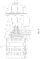
FIG. 2 is a rear right perspective view of a first embodiment of a powertrain assembly of the series hybrid utility vehicle of the present invention; -
FIG. 3 is a rear left perspective view of a driveline of the series hybrid utility vehicle ofFIG. 2 ; -
FIG. 4 is a rear right fragmented perspective view of the drivetrain ofFIG. 2 in the frame; -
FIG. 5 is a rear left fragmented perspective view of the drivetrain ofFIG. 4 ; -
FIG. 6 is a right side view of the drive train ofFIG. 2 ; -
FIG. 7 is an exploded view of a portion of the power train with the motor/ generator exploded away from the transmission; -
FIG. 7A is an enlarged portion of the coupling mechanism shown inFIG. 7 ; -
FIG. 8 is an exploded view showing the motor/generator and the mounting bracket; -
FIG. 9 is a partial cross-sectional view showing the coupling between the motor/generator and the transmission; -
FIG. 10 is a cross-sectional view through lines 10-10 ofFIG. 6 illustrating the power flow between various components of the hybrid utility vehicle ofFIG. 2 in various drive modes; -
FIG. 10A is a view similar to that ofFIG. 10 , showing the drive mode with the engine drive only in high gear; -
FIG. 10B is a view similar to that ofFIG. 10 , showing the drive mode with the engine and motor drive in low gear defining a "Charge-and-Drive" drive mode; -
FIG. 10C is a view similar to that ofFIG. 10 , showing a full performance drive mode with the engine and motor/generator drive in low gear; -
FIG. 10D is a view similar to that ofFIG. 10 , showing the drive mode with the motor drive only in low gear; -
FIG. 10E is a view similar to that ofFIG. 10 , showing a "Charge-at-Rest" drive mode; -
FIG. 11 is a rear right perspective view of a second embodiment of a powertrain assembly of the series hybrid utility vehicle not belonging to the present invention; -
FIG. 12 is a rear right fragmented perspective view of the drivetrain ofFIG. 11 in the frame; -
FIG. 13 is a right side view of the drive train ofFIG. 11 ; -
FIG. 14 is a front left perspective view showing the motor coupled to the transmission for the embodiment ofFIG. 11 ; -
FIG. 15 is a rear right perspective view showing the motor coupled to the transmission for the embodiment ofFIG. 11 ; -
FIG. 16 is a cross-sectional view through lines 16-16 ofFIG. 13 illustrating the power flow between various components of the hybrid utility vehicle ofFIG. 11 in various drive modes; -
FIG. 16A is a view similar to that ofFIG. 16 , showing a "Charge-and-Drive" drive mode in high gear; -
FIG. 16B is a view similar to that ofFIG. 16 , showing a "Charge-and-Drive" drive mode in low gear; -
FIG. 16C is a view similar to that ofFIG. 16 , showing a full performance drive mode with the engine and motor drive in low gear; -
FIG. 16D is a view similar to that ofFIG. 16 , showing a full performance drive mode with the engine and motor drive in low gear; -
FIG. 16E is a view similar to that ofFIG. 16 , showing the drive mode with the motor drive only; -
FIG. 16F is a view similar to that ofFIG. 16 , showing a "Charge-at-Rest" drive mode in low gear; -
FIG. 16G is a view similar to that ofFIG. 16 , showing a "Charge-at-Rest" drive mode in high gear; -
FIG. 17 is a schematic view of a controls system of the vehicle ofFIG. 1 ; -
FIG. 18 is a controls diagram of a first drive or control mode for operating the vehicle ofFIG. 1 ; -
FIG. 19 is a controls diagram of a second drive or control mode for operating the vehicle ofFIG. 1 ; and -
FIG. 20 is a controls diagram of a third drive or control mode for operating the vehicle ofFIG. 1 . - Corresponding reference characters indicate corresponding parts throughout the several views. Although the drawings represent embodiments of the present invention, the drawings are not necessarily to scale and certain features may be exaggerated in order to better illustrate and explain the present invention.
- The embodiments disclosed below are not intended to be exhaustive or to limit the invention to the precise forms disclosed in the following detailed description. Rather, the embodiments are chosen and described so that others skilled in the art may utilize their teachings. While the present disclosure is primarily directed to a utility vehicle, it should be understood that the features disclosed herein may have application to other types of vehicles such as other all-terrain vehicles, motorcycles, snowmobiles, and golf carts.
- Referring first to
FIGS. 1-3 , an illustrative embodiment of ahybrid utility vehicle 10 is shown, and includes ground engaging members, including frontground engaging members 12 and rearground engaging members 14, a powertrain assembly 16 (FIG. 2 ), aframe 20, a plurality ofbody panels 22 coupled toframe 20, afront suspension assembly 24, arear suspension assembly 26, and arear cargo area 28. In one embodiment, one or moreground engaging members U.S. Patent Nos. 8,109,308, filed on March 26, 2008 (Attorney Docket No. PLR-09-25369.02P);8,176,957, filed on July 20, 2009 (Attorney Docket No. PLR-09-25371.01P); and9,108,470, filed on November 17, 2010 U.S. Patent Application Publication No. 2013/0240272, filed on March 13, 2013 (Attorney Docket No. PLR-09-25201.02P).Vehicle 10 may be referred to as a utility vehicle ("UV"), an all-terrain vehicle ("ATV"), or a side-by-side vehicle ("SxS") and is configured for travel over various terrains or surfaces. Furthermore, vehicle may be similar to that disclosed inU.S. Patent application publication 20170355259 . More particularly,vehicle 10 may be configured for military, industrial, agricultural, or recreational applications. -
Powertrain assembly 16 is operably supported onframe 20 and is drivingly connected to one or more ofground engaging members FIGS. 2-5 ,powertrain assembly 16 may include an engine 30 (FIG. 2 ) and a transmission, for example a continuously variable transmission ("CVT") 32 (FIG. 3 ) and/or ashiftable transmission 34.Transmission 34 is shown as a transaxle which includes a combination shiftable transmission and final drive. However, the transmission and final drive may be separated and coupled together as shown inU.S. Patent 8,596,405 .Engine 30 may be a fuel-burning internal combustion engine, however, any engine assembly may be contemplated, such as hybrid, fuel cell, or electric engines or units. In one embodiment,powertrain assembly 16 includes a turbocharger (not shown) andengine 30 is a diesel internal combustion engine. Additional details ofCVT 32 may be disclosed inU.S. Patent No. 3,861,229 ;U.S. Patent No. 6,120,399 ;U.S. Patent No. 6,176,796 ;U.S. Patent No. 6,860,826 ; andU.S. Patent No. 6,938,508 . - As shown in
FIG. 1 ,front suspension assembly 24 andrear suspension assembly 26 may be similar to that described inU.S. Patent No. 7,819,220, filed July 28, 2006 . Alternatively,rear suspension assembly 26 may be as shown and described inU.S. Patent Application Publication No. 2012/0031693, filed August 3, 2010 , titled "SIDE-BY-SIDE ATV. - Referring again to
FIG. 1 ,vehicle 10 includes an operator area 40 supported byframe 20, and which includes seating for at least an operator and a passenger. Illustratively, one embodiment ofvehicle 10 includes three seats, including anoperator seat 42, afront passenger seat 44, and amiddle seat 46.Operator seat 42 includes a seat bottom and a seat back. Similarly, front passenger seats 44 and 46 include a seat bottom and a seat back. - As described above,
vehicle 10 includesframe 20 supported byground engaging members FIGS. 4 and5 ) supportspowertrain assembly 16 andrear cargo area 28.Vehicle 10 also comprises an overhead orupper frame portion 50.Upper frame portion 50 is coupled to frame 20 and cooperates with operator area 40 to define a cab ofvehicle 10. Additional details ofvehicle 10 may be disclosed inU.S. Patent No. 8,998,253, filed March 28, 2013 . - Referring to
FIGS. 2 and3 , in one embodiment,vehicle 10 is a series hybrid utility vehicle configured for engine and electrical operation.Vehicle 10 includes a motor/generator 60 operably coupled totransmission 34 to provide input power to the transmission as further described herein.Vehicle 10 further includes a plurality ofbatteries 70 for driving motor/generator 60 and which can be charged by theengine 30 as further described herein. While only onebattery 70 is shown, it should be understood that multiple batteries may be coupled together or a battery pack may be provided. Anengine control unit 74 is provided to assist in the control of the motor/generator 60. As shown best inFIG. 3 ,vehicle 10 further includes a transmission rear output at 78 for coupling to half shafts (not shown) to drive therear wheels 14, and afront output 80 which couples to adrive shaft 82 which in turn is coupled to a frontfinal drive 84 having a front output at 86. It should be appreciated that half shafts (not shown) are coupled to thefront wheels 12 and driven by output at 86. - With reference again to
FIGS. 4 and5 ,powertrain 16 is shown mounted withinrear frame portion 48. As shown,rear frame portion 48 includes alower frame portion 90 which supportsengine 30 andtransaxle 34.Rear frame portion 48 further includesupstanding posts 92 coupled tolongitudinal rails 94 which support rearwardly extendingframe tubes 96 which enclose thepowertrain 16 yet provide support for utility bed 28 (FIG. 1 ). Aseat support 98 is provided which is supported bylongitudinal frame tubes 94 and enclosebattery 70 andengine control unit 74.Seat support 94 supports the operator andpassenger seats - With reference now to
FIGS. 6-8 , the mounting of the motor/generator 60 and the coupling to thetransaxle 34 will be described in greater detail. As shown best inFIG. 7 ,transaxle 34 includes anupper input shaft 100 which is internally split to provide ashaft portion 102 andshaft portion 104.Shaft portion 102 receives power input fromCVT 32 whereasshaft portion 104 receives power input from motor/generator 60. As is known,engine 30 would drive a drive clutch ofCVT 32 which internally drives a driven clutch ofCVT 32, and the driven clutch ofCVT 32 would couple to theshaft portion 102. The hybrid drive aspect will now be described in greater detail herein, with a first discussion regarding the mounting of the motor/generator 60 to thetransmission 34. - With reference now to
FIGS. 7 ,7A and8 ,transaxle 34 includes three threaded posts or studs 110 (FIG. 7A ) extending outwardly from ahousing 112 of the transaxle on the same side of the transaxle asshaft portion 104. As described herein,studs 110 correspond with lock nuts 114. As shown best inFIG. 7 , a mountingassembly 120 is provided for mounting motor/generator 60 to thetransaxle 34. As shown inFIGS. 7 and7A , mountingassembly 120 includes aspacer 124, locknuts inner bracket 130, bearing 132 andouter bracket 134.Spacer 124 includes a threadedportion 140, ahexagonal portion 142 and a threadedportion 144. It should be appreciated that thetransaxle housing 112 includes a threadedopening 146 positioned aroundshaft portion 104, which threadedly receives threadedportion 140 ofspacer 124.Spacer 124 also includes an opening at 148 which is larger thanshaft portion 104 such that whenspacer 124 is threaded intoopening 146,shaft portion 104 extends throughspacer 124 but does not contactspacer 124.Lock nut 126 is threaded onto threadedportion 144 ofspacer 124 and may float in order to define the lateral position ofinner bracket 130 as described herein. - Once
coupler 124 is attached to threadedopening 146,inner bracket 130 may be mounted totransaxle 34. As shown best inFIG. 7A ,inner bracket 130 includes three apertures at 150 which correspond with threadedposts 110 such thatinner bracket 130 may be positioned overtransaxle 34. It should also be appreciated thatlock washer 126 is moved to an inward most position to allow the positioning ofinner bracket 130.Inner bracket 130 includes an opening at 160 which includes anenlarged diameter portion 162, reduceddiameter portion 164,shoulder 166 andopening 168. It should be appreciated that threadedportion 144 ofspacer 124 may be received throughopening 168 ofinner bracket 130 and thatlock washer 128 is positioned throughopening 162 and is threadably received on the threadedportion 144 which protrudes throughopening 168. Bearing 132 is then received within thediameter portion 162 ofopening 160. This can be seen best in the cross-sectional view ofFIG. 9 . With bearing 132 positioned withindiameter portion 162,shaft 104 is carried within thebearing 132.Lock nuts bracket 130, as shown best inFIG. 9 .Lock nuts 114 are also coupled to the threadedstuds 110, which couples theinner bracket 130 to thetransmission 34. -
Outer bracket 134 is shown best inFIG. 8 , and includes a plurality of recessedopenings 170 which align with threadedbosses 172 on motor/generator 60 to receivecap screws 174 therethrough to couple theouter bracket 134 to the motor/generator 60.Outer bracket 134 further includesopenings 180 which align with threadedopenings 182 on motor/generator 60 and receivefasteners 184 therethrough to further coupleouter bracket 134 to motor/generator 60. The twobrackets shaft portion 104 withoutput shaft 190 of motor/generator 60.Shaft 190 is internally splined which couples withshaft portion 104.Brackets fasteners 200 extending throughapertures 202 ofbracket 130 and into threadedopenings 204 ofouter bracket 134. As shown inFIG. 7 ,fasteners 210 may also be received throughapertures 212 ofbracket 134 and into threaded engagement with threadedapertures 214 ofbracket 130. Thus as coupled together as described above, either the motor/generator 60 orCVT 32 may provide input power to the transaxle throughcorresponding input shafts - With reference now to
FIG. 10 , the inner gearing of thetransaxle 34 will be described in greater detail. As shown,shaft portions coupler 220. The end ofshaft 102 has a splined portion at 222 and the end ofshaft 104 has asplined portion 224, where both splinedportions coupler 220.Coupler 220 is laterally movable along the direction of arrow designated as 226 such that when in the position shown inFIG. 10 , the two. 104 are coupled together and act as one. If thecoupler 220 is moved to the left as viewed inFIG. 10 ,shaft portion 104 is decoupled fromshaft portion 102 whereas when the coupler is moved to the right as viewed inFIG. 10 ,shaft portion 102 is decoupled fromshaft portion 104. As shown,shaft portion 102 includes a gear at 230 andshaft portion 104 includes a gear at 232. Anintermediate shaft 240 is provided which provides agear 242 in meshing engagement withgear 230 and agear 244 in meshing engagement withgear 232.Shaft 240 further includes agear 246. As shown inFIG. 10 ,gear 242 may be laterally movable in the direction ofarrow 248, for example by way of a dog clutch (not shown) wherebygear 242 may be moved into and out of meshing engagement withgear 230. In a similar manner, and as shown inFIG. 10 ,gear 244 may be laterally movable in the direction ofarrow 249, for example by way of a dog clutch (not shown) wherebygear 244 may be moved into and out of meshing engagement withgear 232. - A
lower shaft 250 is provided having agear 252 in meshing engagement withgear 246 andshaft 250 includes agear 254 in meshing engagement with agear 256. It should be appreciated thatgear 256 provides the output to transaxleoutputs 78 and 80 (FIG. 3 ). It should also be appreciated that a combination ofgears gears FIG. 10 , apower path 260 provides for an engine drive for low gear,power path 262 provides engine drive for a high gear,power path 264 provides for a charge at rest mode,power path 266 provides a charge and drive mode andpower path 268 provides a motor only drive in low gear. The various modes will now be described with relation toFIGS. 10A-10E . - With reference first to
FIG. 10A , the engine only in high gear power path is shown wherecoupler 220 is shown moving to the right alongpath 226 such thatshaft portion 104 is decoupled fromshaft portion 102. Thus, power from theCVT 34 toshaft 102 provides power alongpower path 280 to power path 282 (throughgears 230, 242), through power path 284 (through shaft 240), through power path 286 (throughgears 246, 252), through power path 288 (through shaft 250) and through power path 290 (throughgears 254, 256). As mentioned above, the power throughpower path 290 provides power to both outputs of the transaxle at 80 and 86. - With reference now to
FIG. 10B , the power path will be described to define a "charge and drive mode" whereby power from only theengine 30 provides input power through the low gear setting oftransaxle 34. In this mode,coupler 220 couples togethershaft portions gear 242 is moved to the right as viewed inFIG. 10B to decouplegear 242 fromgear 230. Thus power moves along power path 300 (throughshaft portions 102 and 104) to power path 302 (throughgears 232, 244), through power path 304 (through shaft 240), and then throughpower paths FIG. 10B , power is also provided to motor/generator 60 (in the generator mode) throughpower path 301 to charge thebatteries 70. - With reference now to
FIG. 10C , a "full performance" mode is shown where input may be received from both theengine 30 and the motor/generator 60 where the power path is virtually identical to that shown inFIG. 10B , with the exception that apower path 310 is also provided from motor/generator 60 throughshaft 104. The power path therefore includesinput power paths power paths - With reference now to
FIG. 10D , an electric only "stealth" mode is shown wherecoupler 220 is moved to the left as viewed inFIG. 10D to a position to decoupleshaft portion 102 fromshaft portion 104. Thus, the motor provides input power along power path 312 (through shaft 104) to power path 314 (throughgears 232, 244), along power path 316 (through shaft 240), through power path 318 (throughgears 246, 252), through power path 320 (through shaft 250) and through power path 322 (throughgears 254, 256). - With reference now to
FIG. 10E , a "charge at rest" mode is shown wherecoupler 220 couples togethershaft portions gears FIG. 10E to decouple them from theircorresponding gears shaft portions shafts generator 60 is utilized for recharging thebatteries 70. - With reference now to
FIGS. 16 -16G , a second embodiment of hybrid drivetrain will be described. With reference first toFIGS. 11-15 , a hybrid drive is shown at 416 which is similar to thehybrid drive 16 described above.Hybrid drive 416 includesengine 430,transaxle 434, motor/generator 460,batteries 470,motor controller 474,transaxle output 478, front output 480 (FIG. 13 ),drive shaft 482, frontfinal drive 484 andfront output 486. The difference in the embodiment ofFIG. 11 from that ofFIG. 2 relates to the manner in which motor/generator 460 is coupled to thetransmission 434. In this embodiment, motor/generator 460 is coupled to thetransaxle 434 by way of abelt 490 and pulleys orsheaves 492, 494 (FIG. 14 ) which provides power into the transaxle as described herein. As shown inFIG. 12 ,hybrid powertrain 416 is packaged in therear frame portion 48 in much the same manner as described above with respect tohybrid powertrain 16.Motor 460 is coupled totransmission 434 by way of mountingassembly 520, as shown best inFIGS. 14 and15 . - With reference now to
FIGS. 16-16G , the operation of thehybrid powertrain 416 will be described in greater detail. With reference first toFIG. 16 ,transmission 434 includes aninput shaft 502 which is a solid shaft having gears at 630 and 632. Asecond shaft 540 is included which includesgears gears shaft 502, respectively.Gear 642 may be moved laterally out of meshing engagement withgear 630 by movement in the direction ofarrow 648 whilegear 644 may be moved into and out of meshing engagement withgear 632 along movement according toarrow 651.Shaft 540 further includes a fifth gear at 646 which couples withgear 652 onshaft 650. A clutch 620 moves laterally in the direction ofarrow 626 which movesgear 652 into and out of meshing engagement withgear 646.Shaft 650 further includes agear 654 which is in meshing engagement withgear 656. It should be appreciated thatgear 656 provides the output to transaxleoutputs 478 and 480 (FIG. 13 ). As withhybrid drive 16,hybrid drive 416 has multiple modes of operation. - With reference first to
FIG. 16A , a "charge and drive" mode in high gear is shown where power intoshaft 502 fromCVT 34 provides power along power path 700 (through shaft 502) to power path 702 (throughgears 630, 642) along power path 704 (through shaft 540) to power path 706 (throughgears 648, 652) to power path 708 (through shaft 650) to power path 710 (throughgears 654, 656). At the same time as shaft is powered by input toshaft 502, apower path 712 is provided which couples to sheave 492 which powers sheave 494 throughbelt 490. This provides charging ofbatteries 70 while the motor/generator 460 is in the generator mode. In this mode,gear 644 moves in the direction ofarrow 651 to disengage fromgear 632. - As shown in
FIG. 16B , a "charge and drive" mode can also be utilized in the low gear whereby power from CVT toinput shaft 502 provides a power path 720 (through shaft 502) to power path 722 (throughgears 632, 644) which provides input toshaft 540 providing a power path 724 (through shaft 540) to power path 726 (throughgears 648, 652) to power path 728 (through shaft 650) and then to power path 730 (throughgears 654, 656). At the same time power is provided toshaft 540, apower path 732 is provided (through shaft 540) topower path 714 provided by thebelt 490 drivingsheaves gear 642 moves in the direction ofarrow 648 to disengage fromgear 630. - With reference now to
FIG. 16C , a "full performance" mode is shown in a low gear, which is substantially similar to the embodiment ofFIG. 16B , with the exception that power is provided from the motor/generator 460 toshaft 540 throughpower path 740 such that the motor/generator 460 is operating in the motor mode and assisting in the driving ofshaft 540. In a similar manner, and as shown inFIG. 16D , a "full performance" mode is shown in high gear which is substantially similar to that described with respect toFIG. 16A , with the exception that power is provided from motor/generator 460 throughpower path 740 to driveshaft 540. - An electric only drive mode is shown in
FIG. 16E where gears 642 and 644 are disengaged such that power from only motor/generator 460 in the motor mode is driven toshaft 540 throughpower path 750 to power path 752 (through shaft 540) to power path 754 (throughgears 648 and 652) toshaft 650 throughpower path 756 and to power path 758 (throughgears 654, 656). - Finally and with respect to
FIG. 16F , a "charge at rest" mode is shown through the low gear such that input from the CVT toshaft 502 provides input to power path 770 (throughgears 632, 644) to power path 772 (through shaft 540) and through power path 774 (throughbelt 490 andsheaves 492, 494). It should be appreciated that clutch 620 in this configuration movesgear 652 in the direction ofarrow 626 to takegear 652 out of meshing engagement withgear 648, such thatshaft 650 is not rotated.Gear 642 is also disengaged fromgear 630 having been moved in the direction ofarrow 648. - A similar charge at rest mode is shown in
FIG. 16G , through the high gear whereby input power toshaft 502 provides input through power path 780 (through shaft 502) to power path 782 (throughgears 630, 642) to power path 784 (through shaft 540) and to power path 786 (throughbelt 490 and drivingsheaves 492, 494). As in the embodiment ofFIG. 16 ,gear 652 is moved byclutch 620 out of meshing engagement withgear 648 by moving gear in the direction ofarrow 626.Gear 644 is also disengaged fromgear 632 having been moved in the direction ofarrow 651. - Finally, a third embodiment of powertrain could be provided where a motor/generator is mounted on the same side as the CVT, where the motor/generator is coupled to the driven CVT pulley. This could be done by a belt and sheaves for example, where one sheave is coupled to the motor/generator (similar to the embodiment shown in
FIG. 14 ) and the other sheave is coupled to the CVT pulley shaft. - With respect to
Fig. 17 , acontrol system 800 ofvehicle 10 may be included to control operation of any of the powertrain assemblies disclosed herein.Control system 800 includes a hybrid control unit ("HCU") 801 which is operatively coupled to various control units through a communications network or device, such as aCAN bus 802. For example,HCU 801 may be operatively coupled to an engine control unit ("ECU") 804, a motor control unit ("MCU") 806, and a transmission control unit ("TCU") 808. It may appreciated thatECU 804 may be the same asengine control unit 74 ofFig. 2 andMCU 806 may the same asmotor controller 474 ofFig. 12 . In this way, various components of the powertrain assemblies disclosed herein may be controlled by individual control units or controllers. However, in other embodiments, the various controllers or control units may be defined as a single controller or control unit but separated by software for individual control of the motor, engine, batteries, and other powertrain components. - Referring still to
Fig. 17 ,HCU 801 is configured to receive inputs or requests from other vehicle components, defined as driver inputs/requests 810. For example, various driver inputs/requests 810 may be provided from the accelerator pedal, the gearbox, and the clutch. In one embodiment, driver inputs/requests 810 may include an input to the accelerator pedal, a requested gearbox position, and a requested driving direction (e.g., forward or reverse). -
Control system 800 may be used to provide various modes for operatingvehicle 10. In one embodiment,vehicle 10 is configured to operate in a Downhill Speed Control Mode, a Hill Hold Control Mode, a Snow Plow Control Mode, and an Electric Drive-Away Control Mode, as disclosed herein. - When
vehicle 10 operates in the Downhill Speed Control Mode,vehicle 10 is driving downhill and, due to gravity, the velocity ofvehicle 10 can increase. Motor/generator braking vehicle 10 to a specific speed without applying the mechanical brake. More particularly, a negative torque may be applied relative to the direction of driving to maintain a constant velocity ofvehicle 10 without the need to apply the mechanical brake when driving downhill. Additionally, when in the Downhill Speed Control Mode,battery 70 may be recharged. For example, motor/generator battery 70 when the charge onbattery 70 is less than 100%. - As shown in
Fig. 18 , when in the Downhill Speed Control Mode,control system 800 may utilize at least one look-up table to determine the torque requested on motor/generator generator generator generator generator vehicle 10 to a smooth stop. In each state, if the accelerator pedal input exceeds the minimum regenerative threshold,vehicle 10 will return an idle state. - Additionally, as shown at 823, the absolute value of motor/
generator Fig. 18 , at 828 shows that the accelerator pedal is sealed from 1-0 for the range of 0 to the regenerative threshold in order to arrive at the signal(s) or input at 826. In may be appreciated that 826 in bothFigs. 18 and19 denote a multiplication of the two input signals. - With respect to 830, the accelerator pedal input is compared to a look-up table at 832 to determine the acceleration torque. The acceleration torque is then used to determine the torque requested for motor/
generator Fig. 18 , the regenerative torque will be scaled to the range of the accelerator pedal between zero and a minimum pedal regenerative input to allow the driver to actively control the braking torque over the throttle accelerator pedal. These regenerative controls ofvehicle 10 may be used to request a regenerative torque or an acceleration torque from motor/generator - When
vehicle 10 operates in the Hill Hold Control Mode,control system 800 preventsvehicle 10 from rolling backwards without applying the brake pedal when stopping on steep grades of terrain. More particularly, motor/generator vehicle 10 or allowvehicle 10 to roll backwards at a controlled and slow speed. - With respect to
Fig. 19 , the open-loop, look-up table approach ofFig. 18 also may be used during the Hill Hold Control Mode. Ifvehicle 10 tends to roll down hill and the accelerator pedal position is zero, then the acceleration torque also will be zero. However, because motor/generator vehicle 10. - To perform various tasks, such as plowing snow or allowing for a load at the front end of
vehicle 10, the operator desires to have the ability to quickly change between forward and reverse. Additionally, when in the forward mode,vehicle 10 must be capable of pushing or otherwise handling heavy loads. When in the Snow Plow Mode,vehicle 10 is driven forward usingengine Engine generator vehicle 10 is driven in reverse, only motor/generator engine vehicle 10 is driving in the forward direction,engine generator vehicle 10 is driving in the reverse direction,engine generator - To allow for improved low-speed drivability and maneuvering,
control system 800 may allowvehicle 10 to be driven in an Electric Drive-Away Control Mode. In this mode, whenvehicle 10 is operating as a hybrid vehicle, whereby bothengine generator vehicle 10,vehicle 10 may initially start moving using only motor/generator vehicle 10 at low speeds. When the speed ofvehicle 10 increases to a predetermined threshold and the clutch engages such that both motor/generator engine vehicle 10 then operates at full performance. - More particularly, as shown in
Fig. 20 , when at 840 in a low-speed drive-away/maneuvering operation ofvehicle 10, only motor/generator vehicle 10 increases above a predetermined threshold, the speed ofengine generator Engine engine generator vehicle 10 at speeds above the threshold,engine generator engine
Claims (12)
- A parallel hybrid power train for a vehicle, comprising:an engine (30);an electric motor/generator (60);a transmission (34) comprising:an input shaft (100) split at a position along a length defining first and second shaft portions (102, 104), wherein the engine (30) is coupled to an outer end of the first shaft portion (102) and the electric motor/generator (60) is coupled to an outer end of the second shaft portion (104), the engine (30) and the electric motor/generator (60) being coupled to opposite ends of the transmission input shaft; andat least a second shaft (240) drivingly coupled to the input shaft (100), wherein the coupling between the input and second shaft is by way of gears, a first gear (230) positioned on the input shaft (100), a second gear (242) positioned on the second shaft (240) and in selective engagement with the first gear (230), the second gear (242) laterally movable along the second shaft (240) and out of engagement with the first gear (230);a coupler (220) positioned over an inner end of the first shaft portion and an inner end of the second shaft portion, such that the first shaft portion and the second shaft portion may be decoupled from each other by movement of the coupler (220) during operation of the parallel hybrid power train; anda final drive assembly operably coupled to the engine (30) and the electric motor/generator (60) via the transmission (34), the final drive assembly being provided for driving ground engaging members of the vehicle.
- The parallel hybrid power train of claim 1, wherein the coupler (220) is movable along the length of the input shaft (100), wherein, when in a first position, the first and second shaft portions (102, 104) are coupled together, and when in a second position, the first and second shaft portions (102, 104) are decoupled from each other.
- The parallel hybrid power train of claim 2, wherein when the coupler (220) is in the first position, the engine (30) drives the input shaft (100) and the electric motor/generator (60) operates in a motor mode and drives the input shaft (100).
- The parallel hybrid power train of claim 2, wherein when the coupler (220) is in the first position, the engine (30) drives the input shaft (100) and the electric motor/generator (60) in a generator mode.
- The parallel hybrid power train of claim 4, wherein when the coupler (220) is in the first position, the input and second shafts are decoupled from each other by the lateral movement of the second gear (242), and the engine (30) drives the electric motor/generator (60) in a generator mode.
- The parallel hybrid power train of claim 1, wherein when the coupler (220) is in the second position, either the engine (30) or electric motor/generator (60) drives the input shaft (100).
- The parallel hybrid power train of claim 1, wherein the first gear (230) is positioned on the first shaft portion (102) and a third gear (232) is positioned on the second shaft portion (104).
- The parallel hybrid power train of claim 7, wherein a fourth gear (244) is positioned on the second shaft (240) and in engagement with the third gear (232).
- The parallel hybrid power train of claim 8, wherein the fourth gear (244) is laterally movable along the second shaft (240) and out of engagement with the third gear (232).
- The parallel hybrid power train of claim 1, further comprising a third shaft (250) coupled to the second shaft (240).
- The parallel hybrid power train of claim 1, wherein the second shaft (240) is axially offset from the input shaft (100).
- The parallel hybrid power train of claim 11, wherein the second shaft (240) is unaligned with the input shaft (100).
Applications Claiming Priority (2)
| Application Number | Priority Date | Filing Date | Title |
|---|---|---|---|
| US16/152,719 US10780770B2 (en) | 2018-10-05 | 2018-10-05 | Hybrid utility vehicle |
| PCT/US2019/054510 WO2020072780A1 (en) | 2018-10-05 | 2019-10-03 | Hybrid utility vehicle |
Related Child Applications (1)
| Application Number | Title | Priority Date | Filing Date |
|---|---|---|---|
| EP24158879.7 Division-Into | 2024-02-21 |
Publications (2)
| Publication Number | Publication Date |
|---|---|
| EP3860874A1 EP3860874A1 (en) | 2021-08-11 |
| EP3860874B1 true EP3860874B1 (en) | 2024-03-27 |
Family
ID=68242890
Family Applications (1)
| Application Number | Title | Priority Date | Filing Date |
|---|---|---|---|
| EP19787558.6A Active EP3860874B1 (en) | 2018-10-05 | 2019-10-03 | Hybrid utility vehicle |
Country Status (5)
| Country | Link |
|---|---|
| US (2) | US10780770B2 (en) |
| EP (1) | EP3860874B1 (en) |
| AU (2) | AU2019355138B2 (en) |
| CA (1) | CA3115239A1 (en) |
| WO (1) | WO2020072780A1 (en) |
Families Citing this family (9)
| Publication number | Priority date | Publication date | Assignee | Title |
|---|---|---|---|---|
| US10648554B2 (en) | 2014-09-02 | 2020-05-12 | Polaris Industries Inc. | Continuously variable transmission |
| CN210309896U (en) * | 2019-06-13 | 2020-04-14 | 赛格威科技有限公司 | Side-by-side all-terrain vehicle |
| CN112776890A (en) * | 2019-11-01 | 2021-05-11 | 九号智能(常州)科技有限公司 | All-terrain vehicle and vehicle body thereof |
| CN214029039U (en) | 2020-09-14 | 2021-08-24 | 赛格威科技有限公司 | Hybrid powertrain and all-terrain vehicle |
| WO2022165160A1 (en) * | 2021-01-29 | 2022-08-04 | Polaris Industries Inc. | Electronically-controlled continuously variable transmission for a utility vehicle |
| CN214728144U (en) * | 2021-03-15 | 2021-11-16 | 赛格威科技有限公司 | Hybrid all-terrain vehicle |
| US11597399B1 (en) | 2021-08-13 | 2023-03-07 | Oshkosh Defense, Llc | Electrified military vehicle |
| US11498409B1 (en) | 2021-08-13 | 2022-11-15 | Oshkosh Defense, Llc | Electrified military vehicle |
| US11872888B2 (en) | 2022-06-03 | 2024-01-16 | Kawasaki Motors, Ltd. | Drive system of hybrid utility vehicle |
Citations (1)
| Publication number | Priority date | Publication date | Assignee | Title |
|---|---|---|---|---|
| US20100307845A1 (en) * | 2008-02-14 | 2010-12-09 | Hisashi Ogata | Hybrid electric automobile |
Family Cites Families (368)
| Publication number | Priority date | Publication date | Assignee | Title |
|---|---|---|---|---|
| US1138122A (en) | 1914-12-19 | 1915-05-04 | Fred A Lambert | Electric motor-vehicle. |
| US1551594A (en) | 1922-10-27 | 1925-09-01 | Walter Maurice | Electric motor vehicle |
| US1989585A (en) | 1933-05-08 | 1935-01-29 | Chester S Bigelow | Oil warmer and cooler |
| GB684794A (en) | 1949-10-07 | 1952-12-24 | Graeft & Stift Automobilfabrik | Improvements in and relating to internal combustion engines |
| US3294190A (en) | 1964-11-05 | 1966-12-27 | Suvor Tosun | Wheel drive and suspension arrangement for transport vehicle |
| US3523592A (en) | 1968-07-26 | 1970-08-11 | Kohler Co | Engine lubrication system |
| US3694661A (en) | 1968-10-18 | 1972-09-26 | Hitachi Ltd | Ac generator directly coupled to an internal combustion engine |
| US3708028A (en) | 1970-12-21 | 1973-01-02 | Boyertown Auto Body Works | Electrically driven vehicles |
| US3861229A (en) | 1972-10-26 | 1975-01-21 | Textron Inc | Centrifugal clutch |
| US3874472A (en) | 1974-01-25 | 1975-04-01 | West Virginia High Bird Corp | Battery powered vehicle drive |
| US4010725A (en) | 1974-11-14 | 1977-03-08 | White Cygnal G | Self-contained engine warmer |
| US4022272A (en) | 1975-11-14 | 1977-05-10 | Chester O. Houston, Jr. | Transmission fluid heat radiator |
| US4042054A (en) | 1975-12-18 | 1977-08-16 | Ward Eugene T | Vehicle and battery pack |
| IT1071519B (en) | 1976-10-13 | 1985-04-10 | Fiat Spa | INTERNAL COMBUSTION ENGINE LUBRICATION OIL CUP |
| DE2823256C2 (en) | 1978-05-27 | 1985-05-23 | Robert Bosch Gmbh, 7000 Stuttgart | Electric generator |
| US4254843A (en) | 1979-07-20 | 1981-03-10 | Han Joon H | Electrically powered vehicle |
| US4405029A (en) | 1980-01-02 | 1983-09-20 | Hunt Hugh S | Hybrid vehicles |
| US4404936A (en) | 1980-04-30 | 1983-09-20 | Mitsubishi Jukogyo Kabushiki Kaisha | Breather device for overhead valve engines |
| US4388583A (en) | 1981-03-06 | 1983-06-14 | Outboard Marine Corporation | Battery charger with transducer for controlling charge rate |
| DE3123633A1 (en) | 1981-06-15 | 1982-12-30 | Klöckner-Humboldt-Deutz AG, 5000 Köln | HEATING SYSTEM WITH LUBRICANT OIL REDUCTION FOR MOTOR VEHICLES |
| US4405028A (en) | 1981-06-18 | 1983-09-20 | Price Cosby G | Drive system for electric vehicles |
| JPS58126434A (en) | 1982-01-23 | 1983-07-27 | Nissan Motor Co Ltd | Smoothing device of torque in internal-combustion engine |
| US4470389A (en) | 1982-02-08 | 1984-09-11 | Kawasaki Jukogyo Kabushiki Kaisha | Breather-lubricator system for engines |
| JPS5939933A (en) | 1982-08-27 | 1984-03-05 | Yamaha Motor Co Ltd | Portable engine driven generator |
| JPS60209616A (en) | 1984-04-02 | 1985-10-22 | Fuji Heavy Ind Ltd | Lubricating apparatus for ohc engine |
| US4602694A (en) | 1984-07-30 | 1986-07-29 | William Weldin | Motor generator electric automotive vehicle |
| US4638172A (en) | 1984-11-27 | 1987-01-20 | Williams George A | Combination, a model vehicle engine and a direct-current generator |
| JPS61135910A (en) | 1984-12-04 | 1986-06-23 | Fuji Heavy Ind Ltd | Lubricant oil cooling device for engine |
| EP0197823A1 (en) | 1985-03-20 | 1986-10-15 | Valeo | Heat exchanger for a motor vehicle, particularly of the type for exhaust gases |
| US4688529A (en) | 1985-07-10 | 1987-08-25 | Kawasaki Jukogyo Kabushiki Kaisha | Lubricating system for horizontal cylinder overhead valve engine |
| US4697660A (en) | 1985-10-31 | 1987-10-06 | Wu C H | Vehicle with multiple power source |
| GB2196486B (en) | 1986-08-25 | 1990-06-06 | Kubota Ltd | Forcedly air-cooled engine generator of vertical shaft-type |
| ES2007680A6 (en) | 1987-08-06 | 1989-07-01 | Fernandez De Velasco Y Sesena | Portable variable radio frequency generator |
| US5036939A (en) | 1987-08-28 | 1991-08-06 | Polaris Industries L.P. | Multiple axle drive vehicle with overrunning roller clutch hubs |
| US5397991A (en) | 1988-07-13 | 1995-03-14 | Electronic Development Inc. | Multi-battery charging system for reduced fuel consumption and emissions in automotive vehicles |
| US4898261A (en) | 1989-04-10 | 1990-02-06 | Brunswick Corporation | Water cooled plastic oil pan |
| DE3914154A1 (en) | 1989-04-28 | 1990-11-08 | Eberspaecher J | HEATING SYSTEM, ESPECIALLY FOR MOTOR VEHICLES, WITH A COMBUSTION ENGINE AND A HEATING UNIT |
| JP2863234B2 (en) | 1989-12-27 | 1999-03-03 | アイシン・エィ・ダブリュ株式会社 | Electric vehicle |
| JP2932607B2 (en) | 1990-05-23 | 1999-08-09 | 日産自動車株式会社 | Electric car |
| JPH04203250A (en) | 1990-11-29 | 1992-07-23 | Mitsubishi Motors Corp | Drive-by-wire type vehicle with travelling load compensating system speed control section |
| DE4106497A1 (en) | 1991-03-01 | 1992-09-03 | Gerhard O Wirges | POWER GENERATOR |
| JP2827568B2 (en) | 1991-04-30 | 1998-11-25 | トヨタ自動車株式会社 | Hybrid vehicle drive system |
| EP0519460B1 (en) | 1991-06-20 | 1997-04-09 | Honda Giken Kogyo Kabushiki Kaisha | Apparatus for detecting remanent stored energy in a storage battery and for warning of reduction in remanent stored energy |
| US5341280A (en) | 1991-09-27 | 1994-08-23 | Electric Power Research Institute | Contactless coaxial winding transformer power transfer system |
| JPH05131848A (en) | 1991-11-15 | 1993-05-28 | Toyota Motor Corp | Hybrid car driving system control device |
| US5241932A (en) | 1991-12-02 | 1993-09-07 | Ryobi Outdoor Products | Operator carried power tool having a four-cycle engine |
| US5251721A (en) | 1992-04-21 | 1993-10-12 | Richard Ortenheim | Semi-hybrid electric automobile |
| US5359247A (en) | 1992-04-27 | 1994-10-25 | Sundstrand Corporation | Cooling arrangement and method for offset gearbox |
| JP2768134B2 (en) | 1992-05-20 | 1998-06-25 | 日産自動車株式会社 | Driving force distribution control device for four-wheel drive vehicle |
| US5255733A (en) | 1992-08-10 | 1993-10-26 | Ford Motor Company | Hybird vehicle cooling system |
| DE4238364A1 (en) | 1992-11-13 | 1994-05-26 | Behr Gmbh & Co | Device for cooling drive components and for heating a passenger compartment of an electric vehicle |
| US5264764A (en) | 1992-12-21 | 1993-11-23 | Ford Motor Company | Method for controlling the operation of a range extender for a hybrid electric vehicle |
| US5586613A (en) | 1993-04-22 | 1996-12-24 | The Texas A&M University System | Electrically peaking hybrid system and method |
| US5407130A (en) | 1993-07-20 | 1995-04-18 | Honda Giken Kogyo Kabushiki Kaisha | Motor vehicle heat storage device with coolant bypass |
| JP3094745B2 (en) | 1993-09-24 | 2000-10-03 | トヨタ自動車株式会社 | Hybrid vehicle power generation control device |
| US5408965A (en) | 1993-10-04 | 1995-04-25 | Ford Motor Company | Internal combustion engine oil pan with oil cooler |
| DE4427322C2 (en) | 1994-08-02 | 2000-07-27 | Wolfgang Hill | Electricity generation unit for series hybrid vehicles and combined heat and power plants |
| JP2790779B2 (en) | 1994-08-22 | 1998-08-27 | 本田技研工業株式会社 | Power generation control device for hybrid vehicle |
| JP2587202B2 (en) | 1994-08-22 | 1997-03-05 | 本田技研工業株式会社 | Power generation control device for hybrid vehicle |
| DE4433836C1 (en) | 1994-09-22 | 1995-11-09 | Daimler Benz Ag | Device for heating an interior of an electric vehicle |
| DE4446485C2 (en) | 1994-12-23 | 2003-06-26 | Daimler Chrysler Ag | Method and device for braking a motor vehicle with hybrid drive |
| DE4447138A1 (en) | 1994-12-29 | 1997-12-11 | Karl Heinz | Arrangement for hybrid drive of vehicle esp. automobile |
| US7036616B1 (en) | 1995-01-17 | 2006-05-02 | Electrion, Inc. | Hydrogen-electric hybrid vehicle construction |
| JP3087884B2 (en) | 1995-04-28 | 2000-09-11 | 本田技研工業株式会社 | Hybrid vehicle power generation control device |
| US6054844A (en) | 1998-04-21 | 2000-04-25 | The Regents Of The University Of California | Control method and apparatus for internal combustion engine electric hybrid vehicles |
| US5546901A (en) | 1995-06-30 | 1996-08-20 | Briggs & Stratton Corporation | Engine housing for an engine-device assembly |
| JP3350314B2 (en) | 1995-09-29 | 2002-11-25 | 富士重工業株式会社 | Hybrid vehicle drive system |
| TW487770B (en) | 1995-12-15 | 2002-05-21 | Honda Motor Co Ltd | Lubricating system in a 4-stroke engine |
| US6047678A (en) | 1996-03-08 | 2000-04-11 | Ryobi North America, Inc. | Multi-position operator-carried four-cycle engine |
| JP3617183B2 (en) | 1996-05-08 | 2005-02-02 | トヨタ自動車株式会社 | Electric vehicle power supply |
| WO1998004431A1 (en) | 1996-07-30 | 1998-02-05 | Denso Corporation | Hybrid car controller |
| US5673668A (en) | 1996-08-05 | 1997-10-07 | Ford Global Technologies, Inc. | Method and apparatus for electronic throttle monitoring |
| DE19637817A1 (en) | 1996-09-17 | 1998-03-19 | Laengerer & Reich Gmbh & Co | Device and method for cooling and preheating |
| JP3190008B2 (en) | 1996-10-09 | 2001-07-16 | 本田技研工業株式会社 | Oil mist generator for lubrication in engines |
| US5804935A (en) | 1997-02-06 | 1998-09-08 | Radev; Vladimir | Drive system for electric vehicles |
| JPH10246106A (en) | 1997-03-03 | 1998-09-14 | Kioritz Corp | Four-cycle internal combustion engine |
| GB9706909D0 (en) | 1997-04-04 | 1997-05-21 | Adds Graham J | Electric vehicles |
| US5971290A (en) | 1997-04-30 | 1999-10-26 | Honda Giken Kogyo Kabushiki Kaisha | Heat exchange system for electric vehicle |
| US6328004B1 (en) | 1997-07-08 | 2001-12-11 | Rynhart Research And Development Company Limited | Internal combustion engines |
| DE19735021B4 (en) | 1997-08-13 | 2009-08-06 | Volkswagen Ag | Drive arrangement for a motor vehicle |
| EP0898352A1 (en) | 1997-08-22 | 1999-02-24 | Ecomag S.A. | Generator-set |
| US5960901A (en) | 1997-09-04 | 1999-10-05 | Corbin Pacific, Inc. | Battery-powered vehicle |
| JP3447937B2 (en) | 1997-11-18 | 2003-09-16 | 本田技研工業株式会社 | Hybrid vehicle |
| DE19800904A1 (en) | 1998-01-14 | 1999-07-15 | Stihl Maschf Andreas | Two stroke motor especially for portable power tools |
| DE19817333C5 (en) | 1998-04-18 | 2007-04-26 | Conti Temic Microelectronic Gmbh | Electric drive unit consisting of electric motor and electronic module |
| US6213079B1 (en) | 1998-06-03 | 2001-04-10 | Fuji Robin Kabushiki Kaisha | Lubricating apparatus for four-cycle engines |
| US6120399A (en) | 1998-06-11 | 2000-09-19 | Product Research And Development, Inc. | Continuously variable transmission driven element |
| JP3559891B2 (en) | 1998-06-22 | 2004-09-02 | 日産自動車株式会社 | Cooling structure of multilayer motor |
| JP3502768B2 (en) | 1998-06-30 | 2004-03-02 | 日産ディーゼル工業株式会社 | Vehicle brake system |
| US6209518B1 (en) | 1998-08-05 | 2001-04-03 | Unisia Jecs Corporation | Method and apparatus for fail safe control of an electronically controlled throttle valve of an internal combustion engine |
| US6276331B1 (en) | 1998-08-05 | 2001-08-21 | Unisia Jecs Corporation | Method and apparatus for fail-safe controlling internal combustion engine with electronic controlled throttle system |
| EP0979929B1 (en) | 1998-08-11 | 2004-12-15 | Wenko AG Burgdorf | Piston engine with rocker arm valve drive |
| JP3694406B2 (en) | 1998-08-28 | 2005-09-14 | 株式会社日立製作所 | Fail-safe control device for electric throttle type internal combustion engine |
| GB2348630B (en) | 1998-09-09 | 2002-12-04 | Luk Lamellen & Kupplungsbau | Drive train |
| US6554088B2 (en) | 1998-09-14 | 2003-04-29 | Paice Corporation | Hybrid vehicles |
| JP2000088679A (en) | 1998-09-16 | 2000-03-31 | Honda Motor Co Ltd | Torque sensor unit |
| US5971123A (en) | 1998-10-09 | 1999-10-26 | Hilliard Corporation | Bi-directional overrunning clutch |
| JP3853527B2 (en) | 1998-10-29 | 2006-12-06 | 三菱電機株式会社 | Output control system for automobile engine |
| JP2000184508A (en) | 1998-12-18 | 2000-06-30 | Nissan Diesel Motor Co Ltd | Hibrid drive system of vehicle |
| IT1309008B1 (en) | 1999-02-24 | 2002-01-15 | Vf Venieri S P A | PROPULSION GROUP FOR FOUR-WHEEL ELECTRIC VEHICLES FOR EARTH-MOVING AND AGRICULTURE |
| US6176796B1 (en) | 1999-03-26 | 2001-01-23 | Polaris Industries Inc. | Continuously variable transmission with clutch having enhanced air cooling |
| JP3558264B2 (en) | 1999-03-29 | 2004-08-25 | 株式会社日立ユニシアオートモティブ | Electric generator unit |
| JP2000301959A (en) | 1999-04-21 | 2000-10-31 | Hitachi Ltd | Power transmission of automobile |
| GB2349483A (en) | 1999-04-28 | 2000-11-01 | Rover Group | An engine-driven generator assembly |
| US6119636A (en) | 1999-06-11 | 2000-09-19 | Fan; Guo Xiang | Portable generator |
| US6217758B1 (en) | 1999-08-06 | 2001-04-17 | Dana Corporation | Oil sump arrangement with integral filter and heat exchanger |
| JP2001055941A (en) | 1999-08-16 | 2001-02-27 | Honda Motor Co Ltd | Engine automatic start/stop controller |
| US6702052B1 (en) | 1999-09-22 | 2004-03-09 | Honda Giken Kogyo Kabushiki Kaisha | Control apparatus for hybrid vehicles |
| DE19953495C2 (en) | 1999-11-06 | 2002-10-24 | Daimler Chrysler Ag | Drive unit for a motor vehicle |
| DE10000253B4 (en) | 2000-01-05 | 2008-04-17 | Zf Sachs Ag | drive system |
| JP3788160B2 (en) | 2000-01-27 | 2006-06-21 | トヨタ自動車株式会社 | Shift control device for continuously variable transmission for vehicle |
| JP2001238303A (en) | 2000-02-24 | 2001-08-31 | Mitsubishi Motors Corp | Regenerative controller of hybrid electric vehicle |
| US6619106B2 (en) | 2000-03-03 | 2003-09-16 | Visteon Global Technologies, Inc. | High-resolution electronic throttle position system |
| JP3784608B2 (en) | 2000-03-21 | 2006-06-14 | 本田技研工業株式会社 | Handheld four-cycle engine |
| US20010052433A1 (en) | 2000-04-14 | 2001-12-20 | Harris Donald B. | Hybrid power supply module |
| US20020179354A1 (en) | 2000-05-02 | 2002-12-05 | Sail D. White Enterprises, Inc. | Extended range electric vehicle |
| US20010043808A1 (en) | 2000-05-19 | 2001-11-22 | Ken Matsunaga | Heating apparatus for vehicle cabin |
| JP2001329823A (en) | 2000-05-23 | 2001-11-30 | Fuji Heavy Ind Ltd | Valve system lubricating structure of ohc type engine and cover member for ohc type engine |
| JP3866486B2 (en) | 2000-05-23 | 2007-01-10 | 富士重工業株式会社 | Lubricating device for OHC type engine |
| JP2001336409A (en) | 2000-05-29 | 2001-12-07 | Kioritz Corp | Internal combustion engine |
| US6397795B2 (en) | 2000-06-23 | 2002-06-04 | Nicholas S. Hare | Engine with dry sump lubrication, separated scavenging and charging air flows and variable exhaust port timing |
| US6359344B1 (en) | 2000-09-12 | 2002-03-19 | Lincoln Global, Inc. | Electric generating domestic implement |
| US6333620B1 (en) | 2000-09-15 | 2001-12-25 | Transportation Techniques Llc | Method and apparatus for adaptively controlling a state of charge of a battery array of a series type hybrid electric vehicle |
| JP2002115573A (en) | 2000-10-10 | 2002-04-19 | Honda Motor Co Ltd | Hybrid vehicle |
| JP3687518B2 (en) | 2000-10-16 | 2005-08-24 | トヨタ自動車株式会社 | Engine preheat start hybrid vehicle |
| EP1205331B1 (en) | 2000-11-14 | 2005-09-07 | Nissan Motor Company, Limited | Driving force control apparatus |
| AT411091B (en) | 2000-11-30 | 2003-09-25 | Kirchberger Roland Dipl Ing | FOUR-STROKE COMBUSTION ENGINE |
| JP3593983B2 (en) | 2001-01-16 | 2004-11-24 | 日産自動車株式会社 | Vehicle driving force control device |
| US6622804B2 (en) | 2001-01-19 | 2003-09-23 | Transportation Techniques, Llc. | Hybrid electric vehicle and method of selectively operating the hybrid electric vehicle |
| US6427797B1 (en) | 2001-02-07 | 2002-08-06 | Hui-Lung Chang | Transmission structure of gearbox of electrically actuated car |
| JP3943340B2 (en) | 2001-02-16 | 2007-07-11 | 富士重工業株式会社 | Bearing case for engine |
| EP1249590B1 (en) | 2001-04-13 | 2008-09-03 | Fuji Jukogyo Kabushiki Kaisha | Engine generator |
| US6777846B2 (en) | 2001-04-16 | 2004-08-17 | Briggs & Stratton Corporation | Vehicle including a three-phase generator |
| US6648785B2 (en) | 2001-12-05 | 2003-11-18 | New Venture Gear, Inc. | Transfer case for hybrid vehicle |
| US6362602B1 (en) | 2001-05-03 | 2002-03-26 | Ford Global Technologies, Inc. | Strategy to control battery state of charge based on vehicle velocity |
| US6513492B1 (en) | 2001-07-31 | 2003-02-04 | General Motors Corporation | Limited acceleration mode for electronic throttle control |
| JP4147756B2 (en) | 2001-08-10 | 2008-09-10 | アイシン・エィ・ダブリュ株式会社 | Electric vehicle drive control device, electric vehicle drive control method, and program |
| US20030070849A1 (en) | 2001-10-17 | 2003-04-17 | Whittaker Clark Thomas | Auxiliary power unit for vehicles |
| JP3745273B2 (en) | 2001-11-30 | 2006-02-15 | 本田技研工業株式会社 | Internal combustion engine control system for vehicle |
| DE10159087C2 (en) | 2001-12-01 | 2003-11-13 | Porsche Ag | Internal combustion engine |
| JP3882994B2 (en) | 2001-12-27 | 2007-02-21 | アイシン・エィ・ダブリュ株式会社 | Motor control unit cooling device |
| US6675562B2 (en) | 2002-02-19 | 2004-01-13 | Robert C. Lawrence | Portable modular implement system |
| US20060027618A1 (en) | 2002-02-20 | 2006-02-09 | Let's Go Aero, Inc. | Electrical generator carrier system |
| US6638195B2 (en) | 2002-02-27 | 2003-10-28 | New Venture Gear, Inc. | Hybrid vehicle system |
| US6909200B2 (en) | 2002-02-28 | 2005-06-21 | Azure Dynamics Inc. | Methods of supplying energy to an energy bus in a hybrid electric vehicle, and apparatuses, media and signals for the same |
| US6591896B1 (en) | 2002-05-23 | 2003-07-15 | Dennis Hansen | Method and system for providing a transmission fluid heat exchanger in-line with respect to an engine cooling system |
| JP4024597B2 (en) | 2002-06-11 | 2007-12-19 | 独立行政法人科学技術振興機構 | Electric vehicle body structure |
| JP4121318B2 (en) | 2002-06-26 | 2008-07-23 | 三菱電機株式会社 | Engine control device for vehicle |
| DE10230941B4 (en) | 2002-07-09 | 2011-07-28 | Robert Seuffer GmbH & Co. KG, 75365 | Method and device for controlling the operating temperature of an internal combustion engine |
| JP2004052672A (en) | 2002-07-19 | 2004-02-19 | Toyota Motor Corp | Hybrid vehicle and control method for it |
| US6935297B2 (en) | 2002-07-24 | 2005-08-30 | Honda Giken Kogyo Kabushiki Kaisha | Lubricating system for 4-cycle engine |
| US6932743B2 (en) | 2002-07-27 | 2005-08-23 | Cummins Inc. | Throttle control and failure accommodation |
| US20050052080A1 (en) | 2002-07-31 | 2005-03-10 | Maslov Boris A. | Adaptive electric car |
| JP3879650B2 (en) | 2002-10-15 | 2007-02-14 | 日産自動車株式会社 | Vehicle control device |
| JP4221998B2 (en) | 2002-10-28 | 2009-02-12 | スズキ株式会社 | Electric equipment fixing structure of vehicle |
| DE10250303A1 (en) | 2002-10-29 | 2004-05-19 | Bayerische Motoren Werke Ag | Cylinder head of an internal combustion engine with a camshaft bearing strip |
| JP2004155264A (en) | 2002-11-05 | 2004-06-03 | Denso Corp | Air conditioner for vehicle |
| US6952061B2 (en) | 2002-11-28 | 2005-10-04 | Honda Motor Co., Ltd | Motor drive unit |
| JP3857222B2 (en) | 2002-11-29 | 2006-12-13 | 本田技研工業株式会社 | Hybrid vehicle driving force control device |
| JP2004187485A (en) | 2002-12-02 | 2004-07-02 | Yamaha Motor Co Ltd | Motor-driven vehicle |
| US6860826B1 (en) | 2002-12-23 | 2005-03-01 | Polaris Industries Inc. | Continuously variable transmission with two piece cam |
| JP3817516B2 (en) | 2002-12-26 | 2006-09-06 | 本田技研工業株式会社 | Drive control apparatus for hybrid vehicle |
| DE10301609A1 (en) | 2003-01-17 | 2004-07-29 | Robert Bosch Gmbh | Motor vehicle for running with a fuel cell source of power has an internal combustion engine and an auxiliary power supply device with a fuel cell |
| ES2285416T3 (en) | 2003-01-28 | 2007-11-16 | Club Car Inc. | HOUSING FOR VEHICLE FEEDING SYSTEMS. |
| JP4078998B2 (en) | 2003-02-04 | 2008-04-23 | トヨタ自動車株式会社 | Vehicle battery mounting structure |
| US7134517B1 (en) | 2003-02-10 | 2006-11-14 | Kaiser Clements J | Dual electric motor four wheel drive personnel carrier |
| US8469133B2 (en) | 2003-02-10 | 2013-06-25 | Bb Buggies Inc. | Dual electric motor four wheel drive personnel carrier |
| JP4246517B2 (en) | 2003-02-17 | 2009-04-02 | 富士重工業株式会社 | Engine generator |
| US6938508B1 (en) | 2003-02-19 | 2005-09-06 | Polaris Industries Inc. | Ventilated clutch having exhaust hub |
| US20040177827A1 (en) | 2003-03-13 | 2004-09-16 | Shore Line Industries, Inc. | Integral baffle and lubricant cooler |
| KR100519258B1 (en) | 2003-03-25 | 2005-10-07 | 최정훈 | electric car |
| US6769391B1 (en) | 2003-04-11 | 2004-08-03 | Eci Engine Co., Ltd. | Four-stroke engine with an oil spray generating assembly for lubrication |
| JP4310683B2 (en) | 2003-05-13 | 2009-08-12 | アイシン・エィ・ダブリュ株式会社 | Drive unit with built-in electric motor |
| JP3943056B2 (en) | 2003-07-18 | 2007-07-11 | 本田技研工業株式会社 | Control device for hybrid vehicle |
| JP4054041B2 (en) | 2003-08-18 | 2008-02-27 | ヤマハ発動機株式会社 | A valve gear having a roller / rocker arm, a 4-cycle engine, and a motorcycle equipped with a 4-cycle engine |
| CN2649780Y (en) | 2003-08-29 | 2004-10-20 | 胡济荣 | Small-sized four-stroke general petrol engine with fog lubrication |
| US6941198B2 (en) | 2003-09-10 | 2005-09-06 | Ford Motor Company | Method for controlling activation of a power source of a hybrid electric vehicle |
| TWM247195U (en) | 2003-09-10 | 2004-10-21 | Univ Nat Chunghsing | Forward/backward movement control structure for electric wheelchair |
| US7258183B2 (en) | 2003-09-24 | 2007-08-21 | Ford Global Technologies, Llc | Stabilized electric distribution system for use with a vehicle having electric assist |
| JP4386704B2 (en) | 2003-10-08 | 2009-12-16 | 本田技研工業株式会社 | Oil reservoir structure of internal combustion engine |
| US7389837B2 (en) | 2003-10-20 | 2008-06-24 | General Motors Corporation | Electric power control system for a hybrid vehicle |
| JP2005130629A (en) | 2003-10-24 | 2005-05-19 | Toyota Motor Corp | Automobile |
| US6915770B2 (en) | 2003-10-27 | 2005-07-12 | Chi-Fang Lu | Lubricating oil supplying structure of an engine |
| JP2005138791A (en) | 2003-11-10 | 2005-06-02 | Nsk Ltd | Steering column device of shock absorbing type |
| JP2005151633A (en) | 2003-11-12 | 2005-06-09 | Honda Motor Co Ltd | Hybrid vehicle |
| US7325526B2 (en) | 2003-11-21 | 2008-02-05 | Husqvarna Outdoor Products Inc. | Four-stroke engine system |
| US20050115748A1 (en) | 2003-11-28 | 2005-06-02 | Lanier Theodore D. | All-wheel drive electric vehicle |
| JP4534122B2 (en) | 2003-12-26 | 2010-09-01 | トヨタ自動車株式会社 | Hybrid system |
| US7224132B2 (en) | 2004-01-22 | 2007-05-29 | Wavecrest Laboratories, Llc. | Portable range extender operable in automatic and manual modes |
| US7449793B2 (en) | 2004-02-18 | 2008-11-11 | Bluwav Systems, Llc | Portable range extender with autonomous control of starting and stopping operations |
| JP4583185B2 (en) | 2004-03-04 | 2010-11-17 | 本田技研工業株式会社 | Multi-cylinder internal combustion engine |
| JP4554252B2 (en) | 2004-03-31 | 2010-09-29 | 本田技研工業株式会社 | Control method for four-wheel drive vehicle |
| US7191855B2 (en) | 2004-04-07 | 2007-03-20 | Vasilantone Michael M | Rotary engine with improved hybrid features |
| JP2005299469A (en) | 2004-04-09 | 2005-10-27 | Toyota Motor Corp | Warmup control device for hybrid vehicle |
| US8047451B2 (en) | 2004-04-16 | 2011-11-01 | Mcnaughton Incorporated | Windshield heat and clean |
| JP2005323425A (en) | 2004-05-07 | 2005-11-17 | Denso Corp | Power generation system for vehicle |
| JP4421381B2 (en) | 2004-06-02 | 2010-02-24 | 三菱電機株式会社 | Internal combustion engine control device |
| US7537070B2 (en) | 2004-06-22 | 2009-05-26 | Bluwav Systems Llc | Autonomous portable range extender |
| US7055454B1 (en) | 2004-07-13 | 2006-06-06 | Polaris Industries Inc. | Vehicle expansion retainer |
| US20060037595A1 (en) | 2004-08-17 | 2006-02-23 | Dave Procknow | Reduced-emission single cylinder engine |
| US7451808B2 (en) | 2004-09-17 | 2008-11-18 | Behr Gmbh & Co. | Exchanging device for motor vehicles |
| US7493766B2 (en) | 2004-09-30 | 2009-02-24 | Gm Global Technology Operations, Inc. | Auxiliary electrical power generation |
| US7332881B2 (en) | 2004-10-28 | 2008-02-19 | Textron Inc. | AC drive system for electrically operated vehicle |
| JP4005594B2 (en) | 2004-11-12 | 2007-11-07 | 本田技研工業株式会社 | Regenerative control device |
| JP2006177265A (en) | 2004-12-22 | 2006-07-06 | Denso Corp | Thermoelectric power generation device |
| DE102005003077B4 (en) | 2005-01-22 | 2011-06-16 | Audi Ag | Drive unit for a motor vehicle |
| JP4648774B2 (en) | 2005-06-23 | 2011-03-09 | 本田技研工業株式会社 | Engine with generator and method of assembling engine with generator |
| TWI323312B (en) | 2005-06-23 | 2010-04-11 | Honda Motor Co Ltd | Gas-liquid separation device of engine |
| DE102005032633A1 (en) | 2005-07-13 | 2007-01-25 | Robert Bosch Gmbh | Method for influencing the temperature of an electromechanical component and device for carrying out the method |
| JP4294012B2 (en) | 2005-07-28 | 2009-07-08 | 三菱電機株式会社 | Electronic throttle control device |
| US7497286B2 (en) | 2005-07-29 | 2009-03-03 | Borgwarner Inc. | Auxiliary electric drive assembly |
| US7624714B2 (en) | 2005-08-03 | 2009-12-01 | Etg Limited | Engine lubrication method |
| EP1749984B1 (en) | 2005-08-03 | 2008-08-27 | ETG Limited | Lubricating device for a power tool four-stroke engine |
| JP4509895B2 (en) | 2005-08-30 | 2010-07-21 | 本田技研工業株式会社 | Internal combustion engine |
| US20070050095A1 (en) | 2005-09-01 | 2007-03-01 | Polaris Industries Inc. | Controller area network based self-configuring vehicle management system and method |
| FR2890606B1 (en) | 2005-09-13 | 2008-11-07 | Renault Sas | METHOD FOR CONTROLLING A MOTOR POWERTRAIN COMPRISING TWO COOLING CIRCUITS |
| JP2009508763A (en) | 2005-09-23 | 2009-03-05 | エーエフエス トリニティ パワー コーポレーション | Plug-in hybrid propulsion power electronics equipment with high-speed energy storage device and control method and apparatus |
| JP4234710B2 (en) | 2005-10-26 | 2009-03-04 | トヨタ自動車株式会社 | Electric vehicle drive control device and control method thereof |
| GB2431704B (en) | 2005-10-26 | 2008-12-03 | Cooper Cameron Corp | Replaceable hirth coupling component |
| JP4539531B2 (en) | 2005-10-26 | 2010-09-08 | トヨタ自動車株式会社 | Vehicle drive device |
| US20070144800A1 (en) | 2005-11-30 | 2007-06-28 | Stone Kevin T | System and method for braking resistor supplemental heating |
| US7780562B2 (en) | 2006-01-09 | 2010-08-24 | General Electric Company | Hybrid vehicle and method of assembling same |
| US7992662B2 (en) | 2006-01-18 | 2011-08-09 | General Electric Company | Vehicle and method of assembling same |
| US7921945B2 (en) | 2006-02-21 | 2011-04-12 | Clean Emissions Technologies, Inc. | Vehicular switching, including switching traction modes and shifting gears while in electric traction mode |
| GB0603452D0 (en) | 2006-02-22 | 2006-04-05 | Ford Global Tech Llc | Hybrid motor vehicle driveline |
| JP4232785B2 (en) | 2006-02-23 | 2009-03-04 | トヨタ自動車株式会社 | Hybrid vehicle |
| JP4691465B2 (en) | 2006-03-30 | 2011-06-01 | 本田技研工業株式会社 | Breather structure of internal combustion engine |
| JP2007278228A (en) | 2006-04-10 | 2007-10-25 | Toyota Motor Corp | Internal combustion engine |
| JP4981348B2 (en) | 2006-04-25 | 2012-07-18 | 本田技研工業株式会社 | Engine lubrication structure |
| US20070251742A1 (en) | 2006-05-01 | 2007-11-01 | Adams Herbert L Iii | Vehicle with hybrid power train providing part-time all-wheel drive |
| US7384357B2 (en) | 2006-05-05 | 2008-06-10 | Ford Global Technologies, Llc | Speed reduction gear train with planetary differential for electric motor axle drive |
| US7834582B2 (en) | 2006-05-11 | 2010-11-16 | Gm Global Technology Operations, Inc. | Method and apparatus for controlling vehicle battery charging |
| FR2902707B1 (en) | 2006-06-26 | 2008-09-05 | Conception & Dev Michelin Sa | REBONDING HARDWARE ARCHITECTURE FOR LOW VOLTAGE POWER SUPPLY STAGE OF A VEHICLE BRAKING SYSTEM OF ALL WHEELS CONNECTED TO AT LEAST ONE ROTATING ELECTRIC MACHINE |
| US7832513B2 (en) | 2006-07-14 | 2010-11-16 | Gm Global Technology Operations, Inc. | Vehicular electrical system and control method therefor |
| US7819220B2 (en) | 2006-07-28 | 2010-10-26 | Polaris Industries Inc. | Side-by-side ATV |
| US7425006B2 (en) | 2006-09-11 | 2008-09-16 | American Axle & Manufacturing, Inc. | Live twist beam axle assembly |
| JP4245624B2 (en) | 2006-09-20 | 2009-03-25 | トヨタ自動車株式会社 | Power supply control device and power supply control method for hybrid vehicle |
| KR20080028174A (en) | 2006-09-26 | 2008-03-31 | 한라공조주식회사 | Heating device for vehicles |
| US7647994B1 (en) | 2006-10-10 | 2010-01-19 | Belloso Gregorio M | Hybrid vehicle having an electric generator engine and an auxiliary accelerator engine |
| EP2097283A2 (en) | 2006-10-13 | 2009-09-09 | The Ohio State University Research Foundation | Powertrain, vehicle and methods |
| US7855466B2 (en) | 2006-12-29 | 2010-12-21 | Cummins Power Generation Ip, Inc. | Electric power generation system with current-controlled power boost |
| US20080299448A1 (en) | 2006-11-20 | 2008-12-04 | Derrick Scott Buck | Battery unit with temperature control device |
| DE102006059591A1 (en) | 2006-12-16 | 2008-06-19 | Zf Friedrichshafen Ag | Hybrid powertrain of a motor vehicle |
| US7918203B2 (en) | 2007-01-25 | 2011-04-05 | Richard D Sposato | Motor oil heating system, product and method |
| JP2008190628A (en) | 2007-02-05 | 2008-08-21 | Toyota Motor Corp | Drive force controller of vehicle |
| JP4228085B2 (en) | 2007-02-07 | 2009-02-25 | トヨタ自動車株式会社 | Vehicle and control method thereof, power output device and control method thereof, and drive device and control method thereof |
| US7641584B1 (en) | 2007-02-21 | 2010-01-05 | Belloso Gregorio M | Vehicle with primary cruiser engine and auxiliary accelerator engine |
| WO2008115461A2 (en) | 2007-03-16 | 2008-09-25 | Polaris Industries Inc. | Vehicle |
| US7717495B2 (en) | 2007-03-16 | 2010-05-18 | Polaris Industries, Inc. | Vehicle with space utilization |
| US8167072B2 (en) | 2007-03-16 | 2012-05-01 | Polaris Industries Inc. | Vehicle with space utilization |
| US7795602B2 (en) | 2007-03-16 | 2010-09-14 | Polaris Industries Inc. | Vehicle |
| US7871106B2 (en) | 2007-03-16 | 2011-01-18 | Polaris Industries Inc. | Method and apparatus related to transportability of a vehicle |
| WO2008115459A1 (en) | 2007-03-16 | 2008-09-25 | Polaris Industries Inc. | Utility vehicle having modular components |
| US20080236920A1 (en) | 2007-03-27 | 2008-10-02 | Swindell Edward Leroy | All-electric motor car |
| US8109308B2 (en) | 2007-03-27 | 2012-02-07 | Resilient Technologies LLC. | Tension-based non-pneumatic tire |
| US8033954B2 (en) | 2007-04-18 | 2011-10-11 | GM Global Technology Operations LLC | Hybrid powertrain with reversing engine and method of control |
| US7637337B2 (en) | 2007-04-19 | 2009-12-29 | Ford Global Technologies, Llc | Transmission oil pan |
| HUP0700301A2 (en) | 2007-04-24 | 2008-12-29 | Andras Fazakas | Circuit arrangement for paraller usage of battery rechargers |
| US20080271937A1 (en) | 2007-05-01 | 2008-11-06 | Ford Global Technologies, Llc | System and method for powering a power consuming vehicle accessory during an off state of the vehicle |
| US8007401B2 (en) | 2007-05-02 | 2011-08-30 | Nissan Motor Co., Ltd. | Hybrid vehicle drive control apparatus and method |
| US7769505B2 (en) | 2007-05-03 | 2010-08-03 | Gm Global Technology Operations, Inc. | Method of operating a plug-in hybrid electric vehicle |
| JP4183013B1 (en) | 2007-05-15 | 2008-11-19 | トヨタ自動車株式会社 | Vehicle and control method thereof |
| DK176934B1 (en) | 2007-05-18 | 2010-05-31 | Hans Jensen Lubricators As | Lubrication apparatus and method for dosing cylinder lubricating oil |
| DE102007024126A1 (en) | 2007-05-24 | 2008-12-04 | Zf Friedrichshafen Ag | Hybrid drive system for a vehicle |
| US7671567B2 (en) | 2007-06-15 | 2010-03-02 | Tesla Motors, Inc. | Multi-mode charging system for an electric vehicle |
| US20090014223A1 (en) | 2007-07-09 | 2009-01-15 | Jones Robert M | Differential for a lightweight vehicle |
| DE102007032726A1 (en) | 2007-07-13 | 2009-01-22 | Dr. Ing. H.C. F. Porsche Aktiengesellschaft | Method for controlling a drive train and drive train |
| TW200905065A (en) | 2007-07-17 | 2009-02-01 | Si-Liang Lin | Engine lubrication loop device |
| JP4962184B2 (en) | 2007-07-18 | 2012-06-27 | トヨタ自動車株式会社 | Vehicle power supply |
| JP4947552B2 (en) | 2007-08-06 | 2012-06-06 | 本田技研工業株式会社 | Vehicle power supply |
| US7913782B1 (en) | 2007-08-17 | 2011-03-29 | Polaris Industries Inc. | Pull behind unit for use with a self-propelled unit |
| GB2452062B (en) | 2007-08-23 | 2012-05-23 | Ford Global Tech Llc | Hybrid electric motor vehicles |
| JP5016421B2 (en) | 2007-09-10 | 2012-09-05 | 株式会社クボタ | Work vehicle transmission structure |
| US8958965B2 (en) | 2007-09-13 | 2015-02-17 | Ford Global Technologies Llc | System and method for managing a powertrain in a vehicle |
| US7692404B2 (en) | 2007-09-24 | 2010-04-06 | Harris Technology, Llc | Charging control in an electric vehicle |
| US8346419B2 (en) | 2007-09-26 | 2013-01-01 | Tesla Motors, Inc. | Operation of a range extended electric vehicle |
| US20090090573A1 (en) | 2007-10-03 | 2009-04-09 | Boone Daniel J | Hybrid electric vehicle and towable trailer that uses renewable solid fuel |
| FR2922821B1 (en) | 2007-10-24 | 2011-12-16 | Thierry Zerbato | DEVICE FOR COUPLING FOR A HYBRID MOTORIZATION OPERATING ACCORDING TO AT LEAST TWO ELECTRICAL / THERMAL-ELECTRIC MODES FOR A VEHICLE. |
| GB0721262D0 (en) | 2007-10-30 | 2007-12-05 | Ford Global Tech Llc | A method for heating the oil of an engine |
| WO2009060765A1 (en) | 2007-11-05 | 2009-05-14 | Mitsubishi Fuso Truck And Bus Corporation | Exhaust gas purifier of hybrid electric car |
| GB0721747D0 (en) | 2007-11-06 | 2007-12-19 | Xylodyne Corp | Hybird electric off road vehicle extender |
| US7497285B1 (en) | 2007-11-15 | 2009-03-03 | Vladimir Radev | Hybrid electric vehicle |
| US8042993B2 (en) | 2007-12-21 | 2011-10-25 | GM Global Technology Operations LLC | Air-cooled power electronics service algorithm |
| US7871348B2 (en) | 2008-01-21 | 2011-01-18 | Ford Global Technologies, Llc | Vehicle hybrid powertrain system and method of operating same |
| US7967100B2 (en) | 2008-01-22 | 2011-06-28 | Yamaha Hatsudoki Kabushiki Kaisha | Utility vehicle |
| JP5194834B2 (en) | 2008-01-24 | 2013-05-08 | 日産自動車株式会社 | VEHICLE ELECTRIC SYSTEM CONTROL DEVICE AND CONTROL METHOD |
| US8567540B2 (en) | 2008-01-25 | 2013-10-29 | Ford Global Technologies, Llc | Drive unit for an electric hybrid vehicle |
| US7762366B2 (en) | 2008-02-05 | 2010-07-27 | Ford Global Technologies, Llc | Axle drive unit for a hybrid electric vehicle |
| US7699737B2 (en) | 2008-02-05 | 2010-04-20 | Ford Global Technologies, Llc | Electric axle drive unit |
| US7832514B2 (en) | 2008-02-05 | 2010-11-16 | Ford Global Technologies, Llc | Axle drive unit for a hybrid electric vehicle |
| JP4547011B2 (en) | 2008-02-13 | 2010-09-22 | トヨタ自動車株式会社 | POWER OUTPUT DEVICE, VEHICLE EQUIPPED WITH THE SAME, DRIVE DEVICE, AND CONTROL METHOD FOR POWER OUTPUT DEVICE |
| US8011461B2 (en) | 2008-02-14 | 2011-09-06 | Illinois Institute Of Technology | Hybrid electric conversion kit for rear-wheel drive, all wheel drive, and four wheel drive vehicles |
| JP2009220765A (en) | 2008-03-18 | 2009-10-01 | Toyota Motor Corp | Control device for hybrid vehicle |
| US8038573B2 (en) | 2008-04-17 | 2011-10-18 | Bayerische Motoren Werke Aktiengesellschaft | Power development for rapid start in full-hybrid drives with optimized traction control |
| US7950486B2 (en) | 2008-06-06 | 2011-05-31 | Polaris Industries Inc. | Vehicle |
| US8079602B2 (en) | 2008-06-06 | 2011-12-20 | Polaris Industries Inc. | Suspension systems for a vehicle |
| JP2009281330A (en) | 2008-05-23 | 2009-12-03 | Toyota Motor Corp | Hybrid vehicle |
| CN201211849Y (en) | 2008-06-04 | 2009-03-25 | 江西江铃汽车集团实业有限公司 | Driving mechanism of four-wheel drive electric motor vehicle |
| FR2932720B1 (en) | 2008-06-20 | 2010-08-20 | Valeo Systemes Thermiques | VENTILATION, HEATING AND / OR AIR CONDITIONING INSTALLATION OF A VEHICLE COMPRISING AT LEAST ONE THERMAL EXCHANGER WITHIN WHICH CIRCULATES A HEAT TRANSFER FLUID |
| US20090321156A1 (en) | 2008-06-25 | 2009-12-31 | Ford Global Technologies, Llc | Hybrid automotive powertrain system and method of operating same |
| US8800706B2 (en) | 2008-07-16 | 2014-08-12 | Polaris Industries Inc. | Floorboard for a vehicle |
| US20100019722A1 (en) | 2008-07-22 | 2010-01-28 | Sanchez david m | Self-Charging Electric Vehicles (SC-EV) Regeneration Component |
| FR2934818B1 (en) | 2008-08-08 | 2011-04-22 | Thierry Zerbato | HYBRID MOTORIZATION FOR A VEHICLE |
| US20100060015A1 (en) | 2008-09-11 | 2010-03-11 | Buker Guy T | Portable generator having a detachable panel |
| US20100065344A1 (en) | 2008-09-12 | 2010-03-18 | Collings Iii John K | Self Propelled Electric Vehicle Recharging Trailer |
| US8353265B2 (en) | 2008-09-12 | 2013-01-15 | Ford Global Technologies, Llc | Efficient vehicle component heating |
| US9108470B2 (en) | 2008-09-29 | 2015-08-18 | Polaris Industries Inc. | Run-flat device |
| US8994494B2 (en) | 2008-10-10 | 2015-03-31 | Polaris Industries Inc. | Vehicle security system |
| US9067483B2 (en) | 2008-10-21 | 2015-06-30 | Maurice W. Raynor | Electric vechicle drive mechanism for driving multiple alternators |
| JP5086973B2 (en) | 2008-11-07 | 2012-11-28 | トヨタ自動車株式会社 | Hybrid vehicle and control method thereof |
| US20100131134A1 (en) | 2008-11-24 | 2010-05-27 | Wallace David L | Self Sustaining Electric Engine Enhancement (SSEEE) |
| DE102008061295A1 (en) | 2008-12-11 | 2010-06-24 | Fev Motorentechnik Gmbh | Electric vehicle with increased range |
| US8157039B2 (en) | 2008-12-22 | 2012-04-17 | Polaris Industries Inc. | Vehicle |
| FR2941179A1 (en) | 2009-01-16 | 2010-07-23 | Renault Sas | ARRANGEMENT OF AN EXTENDER OF AUTONOMY ON AN ELECTRIC MOTOR VEHICLE |
| FR2941424B1 (en) | 2009-01-28 | 2012-08-17 | Renault Sas | SYSTEM AND METHOD FOR MANAGING AN EXTENDER OF AUTONOMY OF AN ELECTRIC VEHICLE |
| US7739005B1 (en) | 2009-02-26 | 2010-06-15 | Tesla Motors, Inc. | Control system for an all-wheel drive electric vehicle |
| US9162558B2 (en) | 2009-06-15 | 2015-10-20 | Polaris Industries Inc. | Electric vehicle |
| FR2946574A1 (en) | 2009-06-16 | 2010-12-17 | Thierry Zerbato | ELECTRIC DOMINANT HYBRID MOTORIZATION FOR A VEHICLE |
| US20100320959A1 (en) | 2009-06-23 | 2010-12-23 | Tomberlin Michael D | Expanded range electric vehicle with off-grid battery charger |
| US8176957B2 (en) | 2009-07-20 | 2012-05-15 | Resilient Technologies, Llc. | Tension-based non-pneumatic tire |
| EP2459953A4 (en) | 2009-07-31 | 2015-10-07 | Carrier Corp | Cooling system |
| CN101648526A (en) | 2009-09-11 | 2010-02-17 | 深圳市陆地方舟电动车有限公司 | Four-drive electric car |
| EP2308708B1 (en) | 2009-09-16 | 2016-08-17 | swissauto powersport llc | Electric vehicle with range extension |
| US9187083B2 (en) | 2009-09-16 | 2015-11-17 | Polaris Industries Inc. | System and method for charging an on-board battery of an electric vehicle |
| CN101701547A (en) | 2009-10-12 | 2010-05-05 | 力帆实业(集团)股份有限公司 | Vehicle-mounted generator of range-extended electric car |
| DE102009051848A1 (en) | 2009-10-28 | 2011-05-05 | Dr. Ing. H.C. F. Porsche Aktiengesellschaft | Internal combustion engine |
| JP4971414B2 (en) | 2009-12-14 | 2012-07-11 | 本田技研工業株式会社 | Control device for hybrid vehicle |
| JP4962555B2 (en) | 2009-12-15 | 2012-06-27 | トヨタ自動車株式会社 | Charging cable housing device and vehicle |
| CN101708694B (en) | 2009-12-16 | 2014-01-22 | 奇瑞汽车股份有限公司 | Control system of mileage increaser of electric vehicle and control method thereof |
| JP4913205B2 (en) | 2009-12-18 | 2012-04-11 | 日立オートモティブシステムズ株式会社 | Electric vehicle braking control device |
| CN102781713B (en) | 2010-01-21 | 2015-12-02 | 电子能量发动机系统有限责任公司 | Hydrocarbon fuel electric system row mixed propulsion system |
| US20110226539A1 (en) | 2010-03-16 | 2011-09-22 | Huss Michael A | Vehicle with removable auxiliary power system |
| DE102010036321A1 (en) | 2010-07-09 | 2012-01-12 | Dr. Ing. H.C. F. Porsche Aktiengesellschaft | Drive system for a motor vehicle and motor vehicle with such a drive system |
| US8613335B2 (en) | 2010-08-03 | 2013-12-24 | Polaris Industries Inc. | Side-by-side vehicle |
| US8006789B2 (en) | 2010-09-02 | 2011-08-30 | Everette Energy, LLC | Electric vehicle with switched reluctance motor power plant |
| GB2486178A (en) | 2010-12-02 | 2012-06-13 | Jaguar Cars | HEV control which dissipates excessive energy when regenerative braking occurs |
| US9352739B2 (en) | 2011-02-15 | 2016-05-31 | GM Global Technology Operations LLC | Method for operating a hybrid vehicle |
| US8597145B2 (en) | 2011-03-17 | 2013-12-03 | American Axle & Manufacturing, Inc. | Torque transfer unit with integrated electric drive motor |
| CN103958260A (en) | 2011-04-08 | 2014-07-30 | 北极星工业有限公司 | Electric vehicle with range extender |
| CN103813924B (en) | 2011-04-28 | 2017-10-24 | 捷豹路虎有限公司 | The method of vehicle and control vehicle |
| DE102011102265A1 (en) | 2011-05-23 | 2012-04-12 | Daimler Ag | Arrangement for power train on structure, particularly vehicle body of motor vehicle, comprises electric machine, which is arranged in vehicle longitudinal direction behind rear axle of motor vehicle |
| US8655532B2 (en) | 2011-06-30 | 2014-02-18 | GM Global Technology Operations LLC | System and method for operating a hybrid vehicle |
| WO2013006949A1 (en) | 2011-07-08 | 2013-01-17 | Consortium De Recherche Brp - Universite De Sherbrooke S.E.N.C. | Electric off-road wheeled vehicle |
| JP2013056629A (en) | 2011-09-08 | 2013-03-28 | Kanzaki Kokyukoki Manufacturing Co Ltd | Hybrid drive system for working vehicle |
| US9242544B2 (en) | 2011-09-23 | 2016-01-26 | Kanzaki Kokyukoki Mfg. Co., Ltd. | Vehicle with electric transaxle |
| US8878469B2 (en) | 2011-11-14 | 2014-11-04 | Polaris Sales Europe Sarl | Process for electrical assistance to the braking of a vehicle and associated motor system |
| US8662239B2 (en) | 2011-12-28 | 2014-03-04 | Kawasaki Jukogyo Kabushiki Kaisha | Series-hybrid vehicle |
| US8936120B2 (en) | 2011-12-29 | 2015-01-20 | Kawasaki Jukogyo Kabushiki Kaisha | Utility vehicle having a front electric motor |
| US9038754B2 (en) | 2011-12-30 | 2015-05-26 | Kawasaki Jukogyo Kabushiki Kaisha | Hybrid vehicle |
| DE102012100865B4 (en) | 2012-02-02 | 2016-10-27 | Gkn Driveline International Gmbh | Drive arrangement with electric machine and motor vehicle with such a drive arrangement |
| US9573422B2 (en) | 2012-03-15 | 2017-02-21 | Polaris Industries Inc. | Non-pneumatic tire |
| US8998253B2 (en) | 2012-03-30 | 2015-04-07 | Polaris Industries Inc. | Folding cab frame |
| US9598067B2 (en) | 2012-08-24 | 2017-03-21 | Eaton Corporation | Control strategy for AWD connection and disconnection |
| US8979694B2 (en) * | 2013-02-22 | 2015-03-17 | GM Global Technology Operations LLC | Hybrid vehicle with power-split and parallel hybrid transmission and method of controlling same |
| CN105189235B (en) | 2013-03-14 | 2018-01-19 | 艾里逊变速箱公司 | The system and method that engine power train is broken in regenerative process for hybrid electric vehicle |
| DE102013005252A1 (en) | 2013-03-27 | 2014-10-02 | Getrag Getriebe- Und Zahnradfabrik Hermann Hagenmeyer Gmbh & Cie Kg | Hybrid powertrain and method for controlling the same |
| US9126581B2 (en) | 2013-05-08 | 2015-09-08 | GM Global Technology Operations LLC | Hybrid powertrain and modular rear drive unit for same |
| US9108615B2 (en) | 2013-09-19 | 2015-08-18 | Borgwarner Inc. | Multimode clutch for a parallel hybrid vehicle |
| JP6193092B2 (en) | 2013-10-30 | 2017-09-06 | 株式会社ユニバンス | Power transmission device |
| KR101601077B1 (en) | 2013-12-18 | 2016-03-08 | 현대자동차주식회사 | Power transmission apparatus for hybrid electric vehicle |
| JP2015196413A (en) | 2014-03-31 | 2015-11-09 | スズキ株式会社 | hybrid four-wheel-drive vehicle |
| US9776625B2 (en) | 2014-04-22 | 2017-10-03 | Panasonic Intellectual Property Management Co., Ltd. | Vehicle drive device |
| CN107207055B (en) | 2015-01-21 | 2020-08-18 | 北极星工业有限公司 | Electric vehicle |
| USD786133S1 (en) | 2015-07-31 | 2017-05-09 | Polaris Industries Inc. | Vehicle |
| FR3041909B1 (en) | 2015-10-02 | 2017-11-24 | Peugeot Citroen Automobiles Sa | POWER UNIT OF A VEHICLE |
| WO2017218225A1 (en) | 2016-06-14 | 2017-12-21 | Polaris Industries, Inc. | Hybrid utility vehicle |
| FR3058696B1 (en) | 2016-11-14 | 2019-10-25 | Renault S.A.S | DEVICE FOR CONTROLLING A ROBOTIZED GEARBOX FOR A MOTOR VEHICLE WITH HYBRID PROPULSION |
| US10639983B2 (en) * | 2017-03-16 | 2020-05-05 | Kubota Corporation | Work vehicle |
-
2018
- 2018-10-05 US US16/152,719 patent/US10780770B2/en active Active
-
2019
- 2019-10-03 CA CA3115239A patent/CA3115239A1/en active Pending
- 2019-10-03 AU AU2019355138A patent/AU2019355138B2/en active Active
- 2019-10-03 US US17/282,652 patent/US20210347243A1/en active Pending
- 2019-10-03 EP EP19787558.6A patent/EP3860874B1/en active Active
- 2019-10-03 WO PCT/US2019/054510 patent/WO2020072780A1/en active Application Filing
-
2022
- 2022-10-19 AU AU2022256136A patent/AU2022256136A1/en active Pending
Patent Citations (1)
| Publication number | Priority date | Publication date | Assignee | Title |
|---|---|---|---|---|
| US20100307845A1 (en) * | 2008-02-14 | 2010-12-09 | Hisashi Ogata | Hybrid electric automobile |
Also Published As
| Publication number | Publication date |
|---|---|
| AU2019355138A1 (en) | 2021-05-27 |
| CA3115239A1 (en) | 2020-04-09 |
| AU2019355138B2 (en) | 2022-11-17 |
| AU2022256136A1 (en) | 2022-11-24 |
| EP3860874A1 (en) | 2021-08-11 |
| US20210347243A1 (en) | 2021-11-11 |
| US20200108709A1 (en) | 2020-04-09 |
| US10780770B2 (en) | 2020-09-22 |
| WO2020072780A1 (en) | 2020-04-09 |
Similar Documents
| Publication | Publication Date | Title |
|---|---|---|
| EP3860874B1 (en) | Hybrid utility vehicle | |
| JP3350314B2 (en) | Hybrid vehicle drive system | |
| US7377877B2 (en) | Gear shift control apparatus for a hybrid vehicle | |
| US9566978B2 (en) | Vehicle and drive control method for the same | |
| CN108349484B (en) | Operation of a drive device of a hybrid vehicle and hybrid vehicle | |
| CN103386977B (en) | The PWTN and its operating method of vehicle | |
| US9102327B2 (en) | Engine start control device for hybrid electric vehicle | |
| US8177004B2 (en) | Control system for drive unit of hybrid vehicle | |
| US9545918B2 (en) | Control device of hybrid vehicle | |
| IL296644B2 (en) | Hybrid utility vehicle | |
| US20140358340A1 (en) | Hybrid electric vehicle | |
| US7191859B2 (en) | Driving apparatus for an electric vehicle | |
| US20050151420A1 (en) | Hybrid electric vehicle powertrain with regenerative braking | |
| US20030162631A1 (en) | Hybrid vehicle system | |
| WO2010058470A1 (en) | Controller of power transmission device for vehicle | |
| US20150065297A1 (en) | Control device for hybrid vehicle | |
| JP2004007972A (en) | Method of controlling hybrid electric automobile | |
| US20070155583A1 (en) | Control device for vehicular drive system | |
| US10343691B2 (en) | Dual-shaft clutchless hybrid transmission | |
| US20180009435A1 (en) | Apparatus for driving rear-wheels of environment-friendly vehicle | |
| CN109693673B (en) | New energy vehicle electric control transmission device with speed reducer | |
| JP2007331418A (en) | Hybrid vehicle drive mechanism and control device | |
| US10752288B2 (en) | Lateral motion control for cornering and regenerative braking energy capture | |
| JP4162471B2 (en) | Drive control device for front and rear wheel drive vehicles | |
| JP3906826B2 (en) | Control device for hybrid four-wheel drive vehicle |
Legal Events
| Date | Code | Title | Description |
|---|---|---|---|
| STAA | Information on the status of an ep patent application or granted ep patent |
Free format text: STATUS: UNKNOWN |
|
| STAA | Information on the status of an ep patent application or granted ep patent |
Free format text: STATUS: THE INTERNATIONAL PUBLICATION HAS BEEN MADE |
|
| STAA | Information on the status of an ep patent application or granted ep patent |
Free format text: STATUS: THE INTERNATIONAL PUBLICATION HAS BEEN MADE |
|
| PUAI | Public reference made under article 153(3) epc to a published international application that has entered the european phase |
Free format text: ORIGINAL CODE: 0009012 |
|
| STAA | Information on the status of an ep patent application or granted ep patent |
Free format text: STATUS: REQUEST FOR EXAMINATION WAS MADE |
|
| 17P | Request for examination filed |
Effective date: 20210501 |
|
| AK | Designated contracting states |
Kind code of ref document: A1 Designated state(s): AL AT BE BG CH CY CZ DE DK EE ES FI FR GB GR HR HU IE IS IT LI LT LU LV MC MK MT NL NO PL PT RO RS SE SI SK SM TR |
|
| DAV | Request for validation of the european patent (deleted) | ||
| DAX | Request for extension of the european patent (deleted) | ||
| P01 | Opt-out of the competence of the unified patent court (upc) registered |
Effective date: 20230514 |
|
| GRAP | Despatch of communication of intention to grant a patent |
Free format text: ORIGINAL CODE: EPIDOSNIGR1 |
|
| STAA | Information on the status of an ep patent application or granted ep patent |
Free format text: STATUS: GRANT OF PATENT IS INTENDED |
|
| INTG | Intention to grant announced |
Effective date: 20231128 |
|
| GRAS | Grant fee paid |
Free format text: ORIGINAL CODE: EPIDOSNIGR3 |
|
| GRAA | (expected) grant |
Free format text: ORIGINAL CODE: 0009210 |
|
| STAA | Information on the status of an ep patent application or granted ep patent |
Free format text: STATUS: THE PATENT HAS BEEN GRANTED |
|
| AK | Designated contracting states |
Kind code of ref document: B1 Designated state(s): AL AT BE BG CH CY CZ DE DK EE ES FI FR GB GR HR HU IE IS IT LI LT LU LV MC MK MT NL NO PL PT RO RS SE SI SK SM TR |
|
| REG | Reference to a national code |
Ref country code: GB Ref legal event code: FG4D |
|
| REG | Reference to a national code |
Ref country code: CH Ref legal event code: EP |
|
| REG | Reference to a national code |
Ref country code: DE Ref legal event code: R096 Ref document number: 602019049090 Country of ref document: DE |