EP3860770B1 - Dosiersystem mit dosierstoff-kühleinrichtung - Google Patents
Dosiersystem mit dosierstoff-kühleinrichtung Download PDFInfo
- Publication number
- EP3860770B1 EP3860770B1 EP19782926.0A EP19782926A EP3860770B1 EP 3860770 B1 EP3860770 B1 EP 3860770B1 EP 19782926 A EP19782926 A EP 19782926A EP 3860770 B1 EP3860770 B1 EP 3860770B1
- Authority
- EP
- European Patent Office
- Prior art keywords
- dosing
- temperature
- assigned
- dosing material
- nozzle
- Prior art date
- Legal status (The legal status is an assumption and is not a legal conclusion. Google has not performed a legal analysis and makes no representation as to the accuracy of the status listed.)
- Active
Links
Images


Classifications
-
- B—PERFORMING OPERATIONS; TRANSPORTING
- B05—SPRAYING OR ATOMISING IN GENERAL; APPLYING FLUENT MATERIALS TO SURFACES, IN GENERAL
- B05C—APPARATUS FOR APPLYING FLUENT MATERIALS TO SURFACES, IN GENERAL
- B05C5/00—Apparatus in which liquid or other fluent material is projected, poured or allowed to flow on to the surface of the work
- B05C5/001—Apparatus in which liquid or other fluent material is projected, poured or allowed to flow on to the surface of the work incorporating means for heating or cooling the liquid or other fluent material
-
- B—PERFORMING OPERATIONS; TRANSPORTING
- B05—SPRAYING OR ATOMISING IN GENERAL; APPLYING FLUENT MATERIALS TO SURFACES, IN GENERAL
- B05C—APPARATUS FOR APPLYING FLUENT MATERIALS TO SURFACES, IN GENERAL
- B05C11/00—Component parts, details or accessories not specifically provided for in groups B05C1/00 - B05C9/00
- B05C11/10—Storage, supply or control of liquid or other fluent material; Recovery of excess liquid or other fluent material
- B05C11/1042—Storage, supply or control of liquid or other fluent material; Recovery of excess liquid or other fluent material provided with means for heating or cooling the liquid or other fluent material in the supplying means upstream of the applying apparatus
-
- B—PERFORMING OPERATIONS; TRANSPORTING
- B05—SPRAYING OR ATOMISING IN GENERAL; APPLYING FLUENT MATERIALS TO SURFACES, IN GENERAL
- B05C—APPARATUS FOR APPLYING FLUENT MATERIALS TO SURFACES, IN GENERAL
- B05C5/00—Apparatus in which liquid or other fluent material is projected, poured or allowed to flow on to the surface of the work
- B05C5/02—Apparatus in which liquid or other fluent material is projected, poured or allowed to flow on to the surface of the work the liquid or other fluent material being discharged through an outlet orifice by pressure, e.g. from an outlet device in contact or almost in contact, with the work
- B05C5/0225—Apparatus in which liquid or other fluent material is projected, poured or allowed to flow on to the surface of the work the liquid or other fluent material being discharged through an outlet orifice by pressure, e.g. from an outlet device in contact or almost in contact, with the work characterised by flow controlling means, e.g. valves, located proximate the outlet
-
- B—PERFORMING OPERATIONS; TRANSPORTING
- B05—SPRAYING OR ATOMISING IN GENERAL; APPLYING FLUENT MATERIALS TO SURFACES, IN GENERAL
- B05D—PROCESSES FOR APPLYING FLUENT MATERIALS TO SURFACES, IN GENERAL
- B05D1/00—Processes for applying liquids or other fluent materials
- B05D1/26—Processes for applying liquids or other fluent materials performed by applying the liquid or other fluent material from an outlet device in contact with, or almost in contact with, the surface
Definitions
- the invention relates to a dosing system for a dosing substance with a dosing device with a housing, comprising a feed channel for dosing substance, a nozzle, an ejection element and an actuator unit coupled to the ejection element and/or the nozzle, and a dosing substance storage holder coupled to the housing or integrated into the housing.
- the invention further relates to a method for operating a dosing system.
- Dosing systems of the type mentioned above are typically used to apply a medium to be dosed to a target surface in a targeted manner.
- micro-dosing technology it is often necessary for very small amounts of a dosing substance to be placed on the target surface with pinpoint accuracy and without contact, i.e. without direct contact between the dosing system and a target surface.
- Such a contactless process is often also referred to as a "jet process”.
- a typical example of this is the dosing of adhesive dots, solder pastes, etc. when assembling circuit boards or other electronic elements, or the application of converter materials for LEDs.
- WO 2017/213920 A1 discloses a system with a nozzle for dosing droplets of a substance onto a surface of a substrate, wherein the dosing substance in the nozzle is set to a specific temperature.
- a key requirement is to deliver the dosing materials to the target surface with high precision, i.e. at the right time, in the right place and in a precisely dosed amount. This can be done, for example, by dispensing the dosing material drop by drop via a nozzle of the dosing system. The medium only comes into contact with the interior of the nozzle and a, usually front, area of an ejection element of the dosing system.
- a preferred method is to eject individual droplets in a type of "ink jet process", as is also used in ink jet printers, among other things.
- the size of the droplets or the amount of medium per droplet can be predetermined as precisely as possible by the structure and control of the nozzle and the effect achieved as a result.
- the dosing material can also be sprayed in a jet.
- a movable ejection element e.g. a plunger
- the ejection element can move inside the nozzle at a relatively high speed towards a nozzle opening. or outlet opening, whereby a drop of the medium is ejected and then retracted again.
- the nozzle of the dosing system itself can be moved in an ejection or retraction direction.
- the nozzle and an ejection element arranged inside the nozzle can be moved towards or away from each other in a relative movement, whereby the relative movement can either be carried out solely by a movement of the outlet opening or the nozzle or at least partially by a corresponding movement of the ejection element.
- the ejection element can also be brought into a closed position by firmly connecting it to a sealing seat in the nozzle opening and remaining there temporarily. Depending on the dosing material, the ejection element can also remain in a retracted position, i.e. away from the sealing seat, without a drop of the medium escaping from the nozzle ("open ink jet process").
- the movement of the ejection element and/or the nozzle is typically carried out with the aid of an actuator system of the dosing system.
- Piezo actuators are preferably used, particularly in applications that require a very fine dosing resolution.
- the present invention can be operated with all common actuator principles, i.e. hydraulically, pneumatically and/or electromagnetically operated actuators can also be used in the dosing system.
- the dosing material is typically heated to a dosing material-specific processing temperature before being ejected from the nozzle.
- Dosing materials with a medium or high viscosity in particular are heated before processing, i.e. before ejection, in order to reduce the viscosity and thus improve the quality of the ejection process, or to enable fluctuations in the dosing material quantity within the scope of permissible fluctuations.
- a lower viscosity of the dosing material can also have a beneficial effect on the longevity of the dosing system, as the components of the dosing system involved in the ejection are subjected to less stress.
- Dosing materials with a medium or high viscosity are, for example, adhesives, solder pastes, casting compounds, thermal pastes, oils, silicones, paints, etc.
- the dosing material is therefore specifically heated at least in the nozzle or within a nozzle chamber of the dosing system.
- the pot life or service life describes the period of time between the manufacture or provision of a, preferably multi-component, dosing material and the end of its processability.
- the material properties of the dosing material can change in such a way that the dosing material can no longer be processed with the desired quality, i.e. it becomes unusable.
- increasing the temperature of the dosing material can lead to a significant shortening of the pot life. This is particularly problematic when processing thermally curing dosing materials, e.g. adhesives.
- heating the dosing material to a processing temperature can result in the dosing material reaching the end of its pot life before processing, i.e. before it is ejected from the nozzle.
- the dosing material is also (co-)heated in a "waiting area" in front of the nozzle, e.g. in the feed area and possibly even in the dosing material reservoir, by means of convection starting from the heated nozzle.
- this can mean that the dosing material that has become unusable has to be disposed of prematurely or a new batch of dosing material has to be provided, which entails additional costs.
- a dosing system according to the invention for a dosing substance comprises a dosing device with a housing, possibly also made up of several parts, wherein the housing has at least one feed channel for dosing substance, a nozzle, an ejection element and an actuator unit coupled to the ejection element and/or the nozzle.
- the ejection element is also referred to synonymously as a tappet, without restricting the invention thereto.
- the dosing material can be dispensed from the dosing system according to the invention in one of the ways explained at the beginning, i.e. the dosing system is not limited to a specific ejection principle. Accordingly, as is usually the case, an ejection element that can be moved at a relatively high speed can be arranged in the nozzle of the dosing system (in particular in the area of the nozzle, e.g. just before the outlet opening) to eject the dosing material from the nozzle. Alternatively or additionally, as mentioned, an outlet opening of the dosing system according to the invention can be designed to be movable.
- the dosing material is dispensed by means of a movable ejection element, e.g. a tappet.
- a movable ejection element e.g. a tappet.
- the invention is not intended to be limited to this.
- the actuator unit of the dosing device can comprise one or more actuators, whereby the respective actuator can be implemented according to one of the actuator principles mentioned above.
- the invention is described below, without being limited thereto, using a dosing system with a piezo actuator. Regardless of the specific design
- the actuator unit is enclosed by the housing of the dosing device, thus separated from the ambient atmosphere of the dosing system.
- the actuator unit is at least temporarily functionally coupled to the ejection element or nozzle.
- the coupling is carried out in such a way that the forces and movements exerted by the actuator are transmitted to the ejection element or nozzle in such a way that this results in a desired, preferably vertical, movement of the ejection element and/or the nozzle for dispensing the dosing material from the nozzle.
- the actuator can act directly on the ejection element, i.e. without further movement-mediating components.
- the actuator unit of the dosing system can also comprise a movement mechanism in order to transmit the movement or deflection of the (piezo) actuator over a certain distance to the ejection element.
- the coupling between the actuator and the ejection element or between the movement mechanism and the ejection element is not a fixed coupling. This means that the respective components are preferably not screwed, welded, glued, etc. together for coupling.
- the components of the dosing device that come into contact with the dosing substance can preferably be combined in a fluidic unit of the dosing device, for example as a structural unit.
- the fluidic unit and the actuator unit can preferably be enclosed in separate partial housings, which can be coupled together, preferably without tools, in order to form the dosing device, i.e. the housing is then formed in several parts.
- At least one dosing material storage holder is coupled directly to the housing of the dosing device.
- a dosing material storage holder or a dosing material reservoir is an area of the dosing system in which fresh dosing material is kept or kept ready until processing.
- the dosing material storage holder can be mounted at least temporarily, in particular during operation of the dosing system, on the housing of the dosing device itself by means of a coupling or interface of the dosing device.
- the coupling can be with the actuator unit and/or the fluidic unit.
- the coupling point is particularly preferably arranged in an area of the fluidic unit. This means that the dosing material storage holder and the dosing device can be "movement-connected" to form a unit, at least temporarily.
- the dosing agent storage holder can also be integrated, preferably permanently, into the housing of the dosing device.
- the housing can have a cavity accessible from outside the dosing system for receiving or storing dosing agent, e.g. in the case of a multi-part housing, preferably in the area of the fluidic unit.
- the dosing agent storage holder can also be implemented using an external "dosing agent tank" located outside the housing and permanently connected to it.
- the dosing system according to the invention therefore comprises at least one dosing device with a housing as explained at the beginning and a dosing agent storage holder that can be coupled to it on site to form a structural unit or integrated into the housing.
- the dosing system also has a plurality of separately controllable temperature control devices, which are each assigned to different defined temperature zones of the dosing system in order to control the respective temperature zones differently.
- the dosing system comprises at least two, preferably at least three, separate temperature zones.
- a temperature zone is understood to be a limited, defined (partial) area or a section of the dosing system, preferably a cavity of the dosing system filled with dosing substance. This can include a dosing substance with a certain (target) temperature and/or a certain (target) viscosity.
- a temperature zone therefore includes at least one temperature-controlled dosing substance volume in a defined area of the housing and/or the dosing substance storage holder.
- a temperature zone can also include segments of the dosing system that enclose the dosing substance volume or delimit it from areas of the dosing system that lie outside the temperature zone, e.g. a number of walls or housing sections.
- the respective temperature control devices are designed to control the dosing material, which is contained in the respective assigned sub-areas of the dosing system, i.e. in the temperature zones, or which interacts with it, to different (target) temperatures, e.g. in order to achieve different (target) viscosities of the dosing material. It is true that (solid) components of the dosing system can also be (co-)temperatured using the temperature control devices.
- the aim of the temperature control is to control the dosing material in two or more defined areas of the dosing system, i.e. in several temperature zones, to be adjusted to different temperatures or viscosities simultaneously by means of the respective temperature control devices.
- the temperature control takes place during operation of the dosing system, i.e. while the dosing material flows through a respective temperature zone or is arranged in it.
- the temperature control devices are designed and arranged in the dosing system in such a way that one temperature control device can control the temperature of a single specific (assigned) temperature zone, in particular the dosing material in it.
- tempering is understood to mean the supply of heat energy or the removal of heat energy into or from the dosing material. If necessary, both processes can also take place simultaneously.
- the individual tempering devices can each comprise at least one heating device and one cooling device, whereby the tempering can take place by means of conduction and/or convection, as will be explained later.
- the heating device and the cooling device of a respective tempering device can preferably be controlled separately by means of separate control and/or regulating circuits of a control and/or regulating unit of the dosing system. This will also be explained in more detail later.
- At least a first temperature zone is assigned to the dosing substance storage holder, with a second temperature zone being assigned to the nozzle.
- the nozzle can preferably have a (hollow) interior space filled with dosing substance, which is referred to as a nozzle chamber.
- the second temperature zone can preferably be assigned to the nozzle chamber.
- the temperature control devices are designed to control the temperature of the dosing substance in at least one area of the dosing substance storage holder differently, preferably lower, than in an area of the nozzle, in particular differently than in a nozzle chamber of the nozzle.
- the two temperature zones are preferably separated from one another by a feed area or feed channel for dosing substance, i.e. they preferably do not directly border one another.
- At least one of the temperature control devices comprises a cooling device with at least one cold source.
- the cold source is preferably designed to actively remove heat energy from a substance in order to achieve a certain cooling capacity.
- the cold source can carry out a cooling process, ie it can actively "generate" cold. Physically, the cold source can also be understood as a heat sink.
- the cold source is designed and interacts with the cooling device in such a way that the cooling device can use the cold "generated” by the cold source to cool the dosing material.
- the cold source itself can essentially form the entire cooling device.
- the cold source can also be coupled to the cooling device, as will be explained later.
- the cooling device is designed to cool the associated temperature zone, in particular the dosing material in the temperature zone, to a specific (target) temperature.
- heat or thermal energy can be specifically extracted from the dosing material using the cooling device, e.g. by means of convection and/or conduction.
- the dosing material can be cooled using the cooling device to a temperature significantly below an ambient temperature of the dosing system.
- the dosing material in the temperature zone can be tempered using the associated tempering device, in particular the cooling device, to a (target) temperature of at most 18°C, preferably of at most 3°C, particularly preferably of at most -30°C.
- the inventive implementation with several temperature control devices for different temperature zones has several advantages: On the one hand, a high degree of precision in the dispensing of the dosing substance can be achieved by means of the dosing system according to the invention, in that the dosing substance can be tempered to an optimum processing temperature in the area of the nozzle by means of an associated tempering device.
- the dosing material in the area of the dosing material storage holder can be cooled to a significantly lower temperature than the processing temperature, e.g. a storage temperature, using the associated temperature control device in order to keep the dosing material stable in the dosing system over a longer period of time.
- the dosing material in the dosing material storage holder can advantageously be cooled in such a way that the dosing material reaches the nozzle at a non-critical (target) temperature and is only brought to the processing temperature shortly before being ejected from the nozzle, i.e. in the nozzle itself. , e.g. to achieve a suitable viscosity for ejecting the dosing material.
- a method for operating a dosing system for dosing dosing material relates to a dosing system with a dosing device with a housing that may also be made up of several parts, the housing comprising at least one feed channel for dosing material, a nozzle, an ejection element and an actuator unit coupled to the ejection element and/or the nozzle.
- the dosing system also has a dosing material storage holder that is directly coupled to the housing or integrated into the housing.
- a plurality of defined temperature zones of the dosing system are tempered differently by means of a plurality of separately controllable tempering devices of the dosing system, with one tempering device being assigned to each temperature zone.
- the tempering devices can be controlled and/or regulated separately by means of a control and/or regulating unit of the dosing system.
- At least two, preferably at least three, temperature zones of the dosing system are tempered differently by means of an associated tempering device.
- at least a first temperature zone associated with the dosing substance storage holder is tempered differently than a second temperature zone associated with the nozzle.
- At least one of the temperature zones is tempered by means of a cooling device (with a cold source) of the associated tempering device.
- the dosing system preferably comprises at least one further separately controllable temperature control device which is assigned to a third temperature zone of the dosing system.
- the third temperature zone is preferably assigned to the feed channel of the dosing system in order to control the dosing material in the feed channel to a (target) temperature, whereby the (target) temperature can differ from a respective (target) temperature of the dosing material in the dosing material storage holder and/or the nozzle.
- the temperature control devices of the dosing system are preferably designed to specifically set a "temperature gradient" of the dosing material in different areas of the dosing system, as will be explained later.
- the temperature control device associated with the feed channel also comprises a cooling device with a cold source as described above.
- the temperature control device associated with the nozzle can also comprise such a cooling device with a cold source.
- the individual cooling devices are designed to be separately controllable.
- the feed channel or feed area is understood to be a (partial) area of the dosing system that extends from the dosing material storage holder to the nozzle.
- the feed channel does not represent a significant (long-term) storage for dosing material, but is more or less continuously flowed through by new dosing material during operation.
- the feed channel can preferably extend between a coupling point for a connectable dosing material storage holder and the interior of a nozzle or the beginning of a nozzle chamber of the nozzle.
- the dosing system can therefore comprise three temperature zones that are to be tempered differently.
- a respective temperature zone can completely encompass a closed active unit or a functional component of the dosing system, i.e., for example, the entire dosing material storage holder.
- the respective temperature control devices can therefore be designed or assigned to the respective temperature zones in such a way that essentially the entire dosing material in the dosing material storage holder, or to temper essentially the entire dosing material in the feed channel or essentially the entire dosing material in the nozzle "predominantly" evenly.
- the respective temperature zones can be directly adjacent to one another or can be connected to one another without interruption.
- a boundary between two temperature zones represents a temperature transition area. This means that the dosing material is not suddenly tempered to a new (target) temperature after passing through a temperature zone boundary, but rather continuously assumes this temperature as a result of the flow through. "Predominantly" evenly tempered therefore means that there can be areas of a temperature zone, e.g. in the area of a temperature zone boundary, in which the dosing material does not (yet) have a corresponding (target) temperature.
- a third temperature control device in the dosing system makes it possible to reliably keep the dosing material in a desired or advantageous (target) temperature range from the time it is made available (in the dosing material storage holder) until it is actually processed (in the nozzle).
- This advantageously means that the dosing material is kept continuously below the processing temperature of the dosing material until it reaches the nozzle, even with a very low dosing material throughput, whereby a shortening of the pot life can be effectively counteracted.
- This is particularly advantageous when processing thermally curing dosing materials, e.g. adhesives.
- the third, separately controllable tempering device can also be used to gradually bring the dosing material to a processing temperature.
- it can be advantageous to temper the dosing material emerging from the dosing material storage holder, which may be very cold, in the feed channel to a new, higher (target) temperature (but below the processing temperature) using the associated tempering device.
- the feed channel can therefore be used for "pre-tempering" the dosing material in order to reduce a temperature difference between the dosing material emerging from the dosing material storage holder and the processing temperature.
- the respective temperature zones not to be directly adjacent to one another, i.e. there can be "gaps" between the temperature-controlled temperature zones.
- the dosing system can comprise (partial) areas to which no temperature control device is assigned.
- the temperature control devices can be designed to temperature control the dosing material only in at least one local part of the dosing material storage holder, or the feed channel, or the nozzle, with other areas of the aforementioned components not being (directly) affected by the temperature control.
- the dosing material could be actively cooled in the cartridge in order to maximize the pot life and then only actively temperature controlled again in the nozzle in order to enable the dosing material to be processed.
- each temperature control device in the dosing system can include a separately controllable cooling device.
- the individual cooling devices use the cold provided by a cold source.
- the cold source it is possible for the cold source to be designed as an essential component of the cooling device.
- the cooling device and the cold source can form a unit, preferably one that is firmly connected.
- the cooling device can then be designed to cool the dosing material of an assigned temperature zone to a (target) temperature in a contact-based manner, i.e. without using a flowing cooling fluid, e.g. by means of conduction.
- the cold source can preferably make use of the principle of thermoelectric cooling.
- each cooling device can preferably comprise at least one (own) cold source.
- a cooling device can comprise at least one Peltier element (as a cold source), which is arranged on the housing or on the dosing material storage holder by means of a holding device (as part of the cooling device) in order to supply the cold to the dosing material of an associated temperature zone with as little loss as possible.
- Peltier element as a cold source
- cooling device it is possible for a single cold source to interact with several, preferably all, cooling devices of a dosing system.
- the cold source can then be (detachably) coupled to a plurality of separately controllable partial cooling circuits.
- the cold source can be coupled to at least two, preferably at least three, separately operated partial cooling circuits are in active contact.
- each of these separately controllable partial cooling circuits is designed to control the temperature of the dosing material in a specific temperature zone.
- a partial cooling circuit is assigned to a specific temperature zone.
- a partial cooling circuit can therefore form the cooling device of an assigned temperature zone.
- a respective partial cooling circuit comprises a number of cooling components or a "heat sink", which is preferably arranged in an area of the housing or the dosing material storage holder.
- a partial cooling circuit is designed to supply the "heat sink” with a flowing gaseous and/or liquid pre-cooled cooling medium of a certain (target) temperature.
- a respective "heat sink” can preferably be designed in the manner of a heat exchanger in order to transfer the cold from the pre-cooled cooling medium to the dosing material as efficiently as possible or to dissipate heat from it accordingly.
- a respective “heat sink” comprises at least one supply opening for a pre-cooled cooling medium, e.g. a coupling point for an external cooling medium supply line.
- the "heat sink” of a respective cooling device can be coupled to the cold source by means of a separate cooling medium supply line, e.g. a temperature-insulated flexible line.
- the "heat sink” can comprise an outlet opening for the cooling medium, e.g. a coupling point for a separate cooling medium discharge line, in order to feed the possibly heated cooling medium back to the cold source.
- the multiple partial cooling circuits are therefore preferably designed to participate in the cold of a shared cold source.
- the cold source is preferably designed and can be controlled in such a way as to selectively supply the individual partial cooling circuits with a cooled cooling medium at different temperatures.
- the (target) temperature of the cooling medium flowing into the cooling device can be controlled by means of a control unit of the dosing system.
- a volume flow of the cooling medium in a respective partial cooling circuit e.g. by means of a separately controllable proportional valve and/or a pump.
- the dosing system is described using a cooling device according to the second embodiment, wherein a shared cold source supplies a plurality of partial cooling circuits with cold.
- a shared cold source supplies a plurality of partial cooling circuits with cold.
- the invention is not intended to be limited to this.
- the cold source is preferably designed to cool a gaseous and/or liquid cooling medium to a specific (target) temperature, i.e. to specifically extract heat or thermal energy from the cooling medium.
- the (target) temperature of the cooling medium can preferably be lower than an ambient temperature of the dosing system as a result of the active cooling.
- the cooling medium can be cooled by means of the cold source so that it has a (target) temperature of at most 18°C, preferably of at most 3°C, particularly preferably of at most -30°C in the area of the respective temperature control device.
- the cold source which can also be referred to as a "cold generation device" can be designed separately, i.e. not as a fixed component of the dosing system.
- the cold source can be arranged "remotely" from the dosing system, with the cooling devices being supplied with cooling medium by means of separate cold transfer devices, e.g. separate cooling medium supply lines.
- the cold source can be operated according to a first embodiment regardless of the temperature and/or humidity of the ambient air of the dosing system or the cold generating device.
- the temperature of the cooling medium can not only be reduced relative to an ambient temperature by means of the cold source, but can also be set to an "arbitrary" value, i.e. the value required with regard to the operation of the dosing system.
- the cold source can make use of the principle of a refrigeration machine.
- the cold source could comprise a compression refrigeration system.
- such a refrigeration machine can be designed to supply a plurality of temperature control devices, possibly also from different dosing systems, with pre-cooled cooling medium. Liquid and/or gaseous media are suitable as cooling medium, with cooling media with a high heat capacity being preferred.
- the cold source can be realized by means of at least one vortex tube.
- the vortex tube is designed to cool the cooling medium to a certain (target) temperature.
- the cooling device can also comprise more than one, i.e. at least two, cold sources.
- the multiple cold sources can be designed to be separately controllable. If the cold used by a cooling device is generated by means of two or more separate "cold-generating" components (cold sources), this is referred to below as a "multi-part" cold source.
- a multi-part cooling source can be implemented using a plurality of vortex tubes.
- each vortex tube can supply a single partial cooling circuit with pre-cooled cooling medium.
- the temperature of the cooled air exiting the respective vortex tube can be regulated by means of an adjustable control valve in the area of a hot air outlet of the vortex tube.
- a volume flow of the air flowing into a vortex chamber of the vortex tube can also be adjusted, e.g. by means of a proportional valve connected upstream of the vortex tube.
- the cold source can particularly preferably comprise a refrigeration machine, e.g. a compression refrigeration system, and at least one downstream vortex tube that interacts with it (multi-part cold source).
- a refrigeration machine e.g. a compression refrigeration system
- at least one downstream vortex tube that interacts with it multi-part cold source.
- a cooling medium that has already been pre-tempered or cooled can be finally cooled to a (target) temperature using the vortex tube.
- the cooling medium can also be cooled to temperatures below a "lowest possible" cooling temperature of a refrigeration machine.
- a (downstream) vortex tube can also interact with a partial cooling circuit.
- the cold source can be used to ensure that a sufficiently large amount of a sufficiently cooled cooling medium is always provided in order to heat the dosing material in one or more temperature zones to specific (target) values. to cool down.
- a sufficiently large amount of a sufficiently cooled cooling medium is always provided in order to heat the dosing material in one or more temperature zones to specific (target) values. to cool down.
- the dosing material can be kept stable in the dosing system over a longer period of time, even under unfavorable ambient conditions, e.g. at particularly high air temperatures.
- a cold compression coil is combined with a (downstream) vortex tube, a very wide or deep control range for cooling the dosing material can be achieved.
- a multi-part cooling source with a plurality of, i.e. two or more, (downstream) vortex tubes enables the individual cooling devices, in particular the partial cooling circuits, to be supplied with a cooling medium at different temperatures.
- the temperature control of the respective temperature zones can also be optimally adapted to dynamic dosing requirements, as will be explained later.
- the cold source can, as previously explained, also be firmly coupled to the cooling device, e.g. by means of a Peltier element arranged on or in the housing.
- a Peltier element arranged on or in the housing.
- Such a design of the cold source is advantageous, for example, when a point-specific or locally limited cooling effect is required.
- an area of the nozzle pointing in the direction of the actuator unit and/or an outer area of the nozzle or the housing can be cooled in a targeted manner.
- the temperature control devices can each comprise a heating device.
- the temperature control device associated with the dosing material storage holder and/or the feed channel and/or the nozzle can each comprise at least one heating device in order to heat the dosing material in the respectively associated temperature zone to a specific (target) temperature.
- the cooling device and the heating device of the respective tempering devices can be designed to be separately controllable.
- the two components are each designed spatially separated from one another, in particular by means of separate elements.
- the heating device and the cooling device can use different (tempering) media to temper the dosing material.
- the respective cooling devices and the heating devices are arranged in the dosing system in such a way that the dosing material can be brought to a (target) temperature as efficiently as possible in an assigned temperature zone.
- the The cooling device and the heating device of a respective tempering device are in active contact with the dosing material of the respectively assigned temperature zone.
- the respective heating device can be implemented by means of at least one electrically heatable element, e.g. a heating wire and/or a heating cartridge in an area of the housing or nozzle.
- the temperature of the dosing material is controlled by conduction, i.e. without direct contact between the heating device and the dosing material.
- the dosing material storage holder can be arranged fixedly in an area of the housing.
- the dosing material storage holder can comprise a dosing material storage container coupled to the housing.
- the dosing agent storage holder can be implemented by means of at least one dosing agent storage container.
- the dosing agent storage container which is also referred to as a dosing agent cartridge, can preferably be mounted directly to the housing, at least temporarily.
- the dosing agent cartridge can comprise a cartridge coupling point in order to reversibly attach the entire cartridge to the coupling point of the housing.
- the cartridge could be flowed or blown with cooling medium from the outside using the associated cooling device.
- the dosing system can comprise a "cartridge receiving unit" in which the cartridge is completely received in the intended assembled state, i.e. when the cartridge is coupled to the housing during operation.
- the cartridge receiving unit is designed to essentially hermetically seal the assembled cartridge from the ambient atmosphere of the dosing system.
- the cartridge receiving unit can comprise at least one closable opening for access to the cartridge and an access opening for the pre-cooled cooling medium, or a coupling point for an external cooling medium supply.
- a flow channel for cooling medium (as a "heat sink”) can be formed in the area between the cartridge and a wall of the cartridge receiving unit that surrounds the cartridge from the outside.
- the cartridge receiving unit can further comprise a Heating device, e.g. in an area of the wall of the cartridge receiving unit facing the cartridge.
- the associated tempering device can be controlled by means of a control unit and/or regulating unit.
- the other tempering devices can also be assigned a respective control unit and/or regulating unit, which is designed to separately control and/or regulate the cooling device and the heating device of the respective tempering device.
- the dosing system can comprise only one (common) control unit and/or regulating unit or be coupled to it in order to control the respective tempering devices by means of separate control and/or regulating circuits.
- control is used below as a synonym for open-loop and/or closed-loop control. This means that even when we talk about open-loop control, the control can at least include a control process.
- closed-loop control a controlled variable (as an actual value) is generally continuously recorded and compared with a reference variable (as a setpoint). The control is usually carried out in such a way that the controlled variable is adjusted to the reference variable. This means that the controlled variable (actual value) continuously influences itself in the control loop's path of action.
- the control unit is preferably designed to control and/or regulate the respective temperature control devices such that the dosing material in the respectively assigned temperature zone is tempered to a predetermined, preferably different, (target) temperature.
- a tempering device can be controlled in such a way that only cooling of the dosing material takes place, i.e. only the cooling device is controlled.
- control unit can also be used to control the heating device of a tempering device.
- the heating power of the heating device can be controlled to temper the dosing material, i.e. to set and maintain a (target) temperature of the dosing material, e.g. by controlling the strength of the electrical current supplied to the heating device.
- the cooling device and the heating device can also be operated in parallel at least at times, i.e. the dosing material in the same temperature zone can be cooled and heated at the same time (principle of "overlapping" control).
- the cooling and heating devices can be controlled or operated largely independently of each other.
- the current state of the other "opposite” component is taken into account (e.g. whether a component is currently "active” or “inactive”).
- the "overlapping control" is controlled in such a way that the consumption of heating energy or cooling medium is as low as possible, i.e. the heating device and the cooling device do not work continuously against each other at full load.
- the principle of "overlapping control” can be used to largely avoid “overshooting” the dosing material temperature beyond a specified (target) temperature.
- a slight, controlled “working against each other” of the heating device and the cooling device can contribute to increased “rigidity” or constancy of the dosing material temperature with respect to external interference.
- a hot-melt adhesive can initially only be liquefied to such an extent in the area of the dosing material storage holder that the dosing material can flow in the dosing system. Only in the nozzle can the viscosity of the hot-melt adhesive be reduced to such an extent (by heating to a processing temperature) that the dosing material can be ejected from the nozzle. This means that the energy required to heat the dosing material can be reduced compared to keeping the dosing material in the dosing system at the processing temperature all the time.
- the (target) temperatures of the dosing material in the individual temperature zones can preferably be determined as part of a temperature management of the dosing material.
- the control unit is preferably designed to calculate and/or carry out a particularly economical temperature management of the dosing material, ie to control the individual temperature control devices accordingly.
- the temperature management can preferably be carried out in such a way that, on the one hand, optimal processing of the dosing material (during ejection) and, on the other hand, the longest possible pot life of the dosing material in the dosing system is achieved.
- control unit can be designed to control and/or regulate a respective temperature control device for controlling the temperature of the dosing material depending on at least one input parameter.
- the individual temperature control devices can be controlled separately, i.e. depending on the same or different input parameters.
- control unit can also be designed to control or determine a (target) temperature of at least one temperature zone depending on an input parameter.
- An input parameter can be stored in the control unit and/or determined by means of a sensor of the dosing system, as explained below.
- the control, in particular the regulation, of a respective temperature control device can be carried out depending on one or more input parameters (as an actual value) in such a way that the dosing material in the respectively assigned temperature zone, preferably essentially in the entire temperature zone, reaches a certain (respective) target value as quickly as possible and/or the target value is kept as constant as possible during operation.
- a target value of the dosing material in the respective temperature zones is kept constant as a result of the regulation even with a high dosing material throughput and/or with dynamic dosing requirements.
- a target value can be, for example, a (target) temperature and/or a (target) viscosity of the dosing material.
- a first input parameter can be a volume flow of the dosing material or a dosing material throughput per unit of time in a temperature zone.
- a (target) temperature of a temperature zone can be dynamically controlled (determined) depending on a current and/or expected volume flow of the dosing material in at least one, preferably in the same, temperature zone.
- a temperature of the dosing material in at least one temperature zone can also be an input parameter for the control unit.
- at least one temperature sensor in the dosing system can be assigned to each respective temperature control device. in order to generate an input parameter for controlling the tempering device.
- the dosing system comprises a number of temperature sensors to separately determine the temperature of the dosing material in an area of the dosing material storage holder, the feed channel and the nozzle.
- the respective sensors can be arranged in direct measuring contact with the dosing material.
- the sensors can be designed to determine or extrapolate the temperature of the dosing material over a certain distance.
- a third input parameter can be a viscosity of the dosing substance in at least one temperature zone.
- the (target) temperature of at least one temperature zone can be dynamically controlled (determined) depending on a viscosity of the dosing substance.
- the input parameter can be determined separately in the temperature zones using a suitable sensor, e.g. a viscometer.
- a suitable sensor e.g. a viscometer.
- the (actual) viscosity of the dosing material can also be calculated, e.g. using a viscosity of the dosing material stored in the control unit (under standard conditions) and the conditions currently prevailing in the dosing material.
- the individual temperature control devices can be controlled in such a way as to achieve a (target) temperature of the dosing material in a respective temperature zone as efficiently as possible.
- control system can also be used to continuously re-determine the (target) temperatures to be achieved in the respective temperature zones or the dosing material in them during operation and thus adapt them to the current conditions of the dosing process.
- external "disturbance factors” e.g. fluctuating ambient temperatures
- internal fluctuations in the operating process e.g. a strongly varying dosing material throughput
- the previously explained temperature management of the dosing material can preferably also be taken into account in a method for operating the dosing system, as explained below.
- the temperature zone associated with the nozzle can be tempered using the associated tempering device in such a way that the temperature of the dosing material in the, preferably substantially entire, temperature zone corresponds to at least one specific processing temperature of the dosing material.
- the temperature control can be carried out in such a way that the temperature of the dosing material is higher than an ambient temperature of the dosing system.
- the temperature control of the temperature zone assigned to the dosing material storage holder can preferably be carried out in such a way that the temperature of the dosing material in the, preferably essentially entire, temperature zone is lower than the temperature of the dosing material in the temperature zone assigned to the nozzle or in the nozzle.
- the temperature control can also be carried out in such a way that the temperature of the dosing material in the dosing material storage holder is lower than the ambient temperature of the dosing system.
- the temperature control of the temperature zone assigned to the feed channel of the dosing system is preferably carried out in such a way that the temperature of the dosing material in this temperature zone, in particular essentially in the entire feed channel, is higher than the temperature of the dosing material in the temperature zone assigned to the dosing material storage holder or in the dosing material storage holder.
- the temperature control can also be carried out in such a way that the temperature of the dosing material in the feed channel is lower than the temperature of the dosing material in the temperature zone assigned to the nozzle.
- a cooling device and a heating device of a respective assigned temperature control device can be controlled separately by means of separately designed control circuits of the control unit.
- the respective tempering devices i.e. the tempering device assigned to the dosing material storage holder, possibly the tempering device assigned to the feed channel and the tempering device assigned to the nozzle
- the respective tempering devices can be controlled separately by means of the control unit in such a way that a defined temperature gradient of the dosing material in the Dosing system is formed.
- the temperature gradient can be formed as a result of the control such that the temperature of the dosing material in the dosing material storage container is lower than the temperature of the dosing material in the feed channel, wherein the temperature in the feed channel is lower than the temperature of the dosing material in the nozzle.
- the respective temperature control devices in the process can be controlled in such a way that the dosing material is gradually heated to a processing temperature over the course of the process, preferably from a stable storage temperature.
- the control is carried out in such a way that the temperature of the dosing material only corresponds to the processing temperature for as short a time as possible, i.e. the dosing material is brought to the final processing temperature as late as possible in the process, preferably only immediately before the ejection process.
- the (target) temperature of the respective temperature zone of the dosing system i.e. the (target) temperature of the dosing material in the temperature zone assigned to the dosing material storage holder and/or in the temperature zone assigned to the feed channel and/or in the temperature zone assigned to the nozzle, can be determined by means of the control unit depending on an actual and/or expected dosing material throughput in a respective temperature zone.
- the (target) temperatures can also be dynamically adapted to fluctuations in the dosing material throughput.
- the respective temperature control devices can also be designed to control the temperature zones to essentially the same temperature. Accordingly, the control unit can control the temperature control devices separately so that the dosing material in the respective temperature zones is controlled to essentially the same temperature.
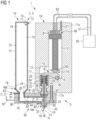
- FIG. 1 A specific embodiment of a dosing system 1 according to the invention is now described.
- the dosing system 1 is shown here in the usual intended position, e.g. when the dosing system 1 is in operation.
- a nozzle 40 is located in the lower area of the dosing system 1, so that the drops of the medium are ejected downwards through the nozzle 40 in an ejection direction R.
- bottom and top are used below, these details always refer to such a usually usual position of the dosing system 1.
- the dosing system 1 can also be used in a different position in special applications and the drops are ejected from the side, for example.
- pressure and exact design as well as control of the entire ejection system this is also possible in principle.
- the dosing system 1 comprises as essential components an actuator unit 10 and a fluidic unit 30, which together form a dosing device 5, and a dosing substance storage holder 70 coupled to the fluidic unit 30.
- the actuator unit 10 and the fluidic unit 30 are firmly connected to one another, e.g. by means of a fixing screw 23, and thus form a housing 11 with two housing parts 11a, 11b.
- the respective assemblies 10, 30 can also be implemented in the manner of plug-in coupling parts that can be coupled to one another to form a quick coupling.
- the actuator unit 10 and the fluidic unit 30 could then be coupled to one another without tools in order to form the dosing system 1.
- the actuator unit 10 and the fluidic unit 30 together form the dosing device 5 of the dosing system 1.
- the actuator unit 10 essentially comprises all components that ensure the drive or movement of an ejection element 31, here a plunger 31, in the nozzle 40, for example a piezo actuator 60 and a movement mechanism 14 in order to be able to actuate the ejection element 31 of the fluidic unit 30, a control unit 50 in order to be able to control the piezo actuator 60 and similar components, as will be explained below.
- the fluidic unit 30 comprises all other parts that are in direct contact with the medium, as well as the elements that are required to assemble the respective parts in contact with the medium together or to hold them in their position on the fluidic unit 30.
- the actuator unit 10 comprises an actuator unit housing block 11a as the first housing part 11a with two internal chambers, namely on the one hand an actuator chamber 12 with a piezo actuator 60 located therein and on the other hand an action chamber 13 into which the movable ejection element 31, here the plunger 31, of the fluidic unit 30 protrudes.
- the plunger 31 Via a movement mechanism 14, which protrudes from the actuator chamber 12 into the action chamber 13, the plunger 31 is actuated by means of the piezo actuator 60 so that the medium to be dosed is ejected from the fluidic unit 30 in the desired amount at the desired time.
- the plunger 31 closes a nozzle opening 41 and thus also serves as a closure element 31.
- an ejection element 31 since the largest part of the medium is only ejected from the nozzle opening 41 when the plunger 31 moves in the closing direction, it is referred to here as an ejection element 31.
- control the piezo actuator 60 To control the piezo actuator 60, it is connected electrically or by signaling to a control unit 50 of the dosing system 1.
- the connection to this control unit 50 is made via control cables 51, which are connected to suitable piezo actuator control connections 62, e.g. suitable plugs.
- the two control connections 62 are each coupled to a contact pin 61 or to a respective connection pole of the piezo actuator 60 in order to control the piezo actuator 60 by means of the control unit 50.
- the control connections 62 can be sealed through the housing 11 in such a way that essentially no air can penetrate from the outside into the actuator chamber 12 in the area of the respective control connections 62, e.g. to be able to cool the actuator 60 effectively.
- the actuator chamber 12 comprises a supply opening 21 for a cooling medium in the upper area in order to supply the piezo actuator 60 with a cooling medium.
- the piezo actuator 60 in particular the piezo actuator control connections 62, can be provided with a suitable storage unit (e.g. an EEPROM or the like) in which information such as an article name etc. or control parameters for the piezo actuator 60 are stored, which can then be read out by the control unit 50 in order to identify the piezo actuator 60 and control it in the appropriate manner.
- the control cables 51 can comprise several control lines and data lines. However, since the basic control of piezo actuators is known, this will not be discussed further here.
- the piezo actuator 60 can expand and contract again in the longitudinal direction of the actuator chamber 12 according to a wiring by means of the control device 50.
- the piezo actuator 60 can be inserted into the actuator chamber 12 from above.
- a spherical cap (not shown here) that can be adjusted in height by a screw movement can then serve as the upper abutment, enabling precise adjustment of the piezo actuator 60 to a movement mechanism 14, here a lever 16.
- the piezo actuator 60 is mounted downwards via a pressure piece 20 that tapers at an acute angle at the bottom on the lever 16, which in turn rests on a lever bearing 18 at the lower end of the actuator chamber 12.
- the lever 16 can be tilted about a tilt axis K via this lever bearing 18, so that a lever arm of the lever 16 projects through an opening 15 into the action chamber 13.
- the opening 15 connects the action chamber 13 with the actuator chamber 12, so that the cooling medium can flow from the actuator chamber 12 into the action chamber 13 and leave the housing 11 in the area of a discharge opening 22.
- the lever arm has a contact surface 17 pointing in the direction of the tappet 31 of the fluidic unit 30 coupled to the actuator unit 10, which presses on a contact surface 34 of a tappet head 33.
- the fluidic unit 30 comprises a second housing part 11b and is connected to the actuator unit 10 or its housing part 11a by means of a fixing screw 23 to form the housing 11, as mentioned.
- the tappet 31 is supported by means of the tappet spring 35 on a tappet bearing 37, to which a tappet seal 36 is connected at the bottom.
- the tappet spring 35 presses the tappet head 33 upwards away from the tappet bearing 37 in the axial direction. This also presses a tappet tip 32 away from a sealing seat 43 of the nozzle 40.
- a nozzle opening 41 is also free or unlocked.
- the dosing material is supplied to the nozzle 40 via a nozzle chamber 42 to which a feed channel 80 leads.
- the feed channel 80 is connected to a dosing material storage holder 70, which is implemented here by means of a dosing material cartridge 70.
- the dosing material cartridge 70 forms the dosing system 1 together with the dosing device 5.
- the dosing agent cartridge 70 is attached directly to the housing 11, here to the second housing part 11b, by means of a coupling point 77 at a cooperating coupling point 44 of the housing 11.
- the interfaces 44, 77 enable a time-saving, preferably tool-free, reversible attachment of the dosing agent storage holder 70 to the housing 11. Since the basic structure of dosing systems is known, for the sake of better clarity, mainly those components are shown here that at least indirectly relate to the invention.
- the dosing system further comprises three tempering devices 2, 2', 2", which are each assigned to different temperature zones of the dosing material.
- a first tempering device 2 is assigned to the dosing material cartridge 70.
- the tempering device 2 comprises a cooling device 3, which is explained in more detail below, and a heating device (not shown).
- the dosing agent cartridge 70 (shown only schematically here) is arranged in the intended state, i.e. coupled to the fluidic unit 30, entirely within a cartridge receiving unit 72 of the cooling device 3.
- the cartridge receiving unit 72 is essentially hermetically sealed by means of a cover and comprises a feed opening 75 for a pre-cooled cooling medium, e.g. a coupling point for an external cooling medium supply line.
- a pre-cooled cooling medium can be fed to a cooling channel 73 by means of the feed opening 75.
- the cooling channel 73 is arranged here in a wall 74 of the cartridge receiving unit 72 and is designed such that it encloses the cartridge 70 in a substantially helical shape.
- the cooling channel 73 ends in a discharge opening 76 by means of which the cooling medium can leave the cooling channel 73 again in a flow direction RM.
- the cartridge receiving unit 72 and then indirectly also the dosing material in the cartridge 70 are cooled by means of the cooling medium.
- the first temperature control device could alternatively or additionally also comprise at least one cooling channel that runs essentially straight, e.g. along a longitudinal extension of the cartridge (here vertically), in the wall of the cartridge receiving unit.
- each cooling channel can comprise a separate supply opening or discharge opening for cooling medium.
- a plurality of separate cooling channels can only be assigned one common (“central") supply opening or discharge opening.
- the cooling channel could be formed between a cartridge wall 71 forming the cartridge and an inner wall of the cartridge receiving unit, i.e. in an interior of the cartridge receiving unit, and thus surround the cartridge from the outside in a ring shape.
- the dosing substance can be tempered to a (first) specific (target) temperature essentially in the entire dosing substance cartridge 70 up to the entry into the feed channel 80.
- the dosing system 1 comprises a second tempering device 2', which is assigned to the feed channel 80.
- the feed channel 80 can, for example, have a substantially circular cross-section.
- the second temperature control device 2' also comprises a (separately controllable) cooling device 3' and a heating device (not shown).
- the cooling device 3' comprises a "cooling body" 82, here a cooling channel 82, which is arranged in a wall 81 of the feed channel 80.
- the cooling channel 82 winds helically around the entire feed channel 80. This means that both the vertical section (adjoining the cartridge 70) and the horizontal section of the feed channel 80 adjoining it, in particular the dosing material in the respective section, are in operative contact with the cooling device 3'.
- the "cooling body" 82 comprises a separate (opposite the supply opening 75 of the cartridge receiving device 72) supply opening 83 for pre-cooled cooling medium, which is connected here to the actual cooling channel 82 by means of a short (horizontal) connecting channel.
- the cooling channel 82 extends to a discharge opening 84 for discharging the cooling medium from the cooling channel 82.
- the second temperature control device could also comprise a plurality of separately formed cooling channels.
- the individual cooling channels could each comprise separate supply openings or discharge openings or be coupled by means of only one common (“central") supply or discharge opening.
- the cooling channels could also be arranged at a distance from the supply channel in the fluidic unit, i.e. the respective cooling channels then do not run directly in a wall of the supply channel.
- a single cooling channel could also be designed in such a way that it encloses the feed channel from the outside in a ring shape (when considering a cross-section of the feed channel) and extends along its course.
- the second tempering device 2' comprises a heating device (not shown) which is arranged in a frame part 45 of the housing 11 and can be controlled by means of heating connection cables 87.
- the dosing material can be tempered to a (second) (target) temperature essentially in the entire feed channel 80.
- a third tempering device 2" of the dosing system 1 is assigned to the nozzle 40 in order to temper the dosing material in a nozzle chamber 42 inside the nozzle 40, which nozzle chamber 42 is directly connected to the feed channel 80, to a (third) (target) temperature.
- This third tempering device 2" comprises a heating device 4", which is implemented here by means of heating elements 85.
- the heating elements 85 can be designed, for example, as an annular heating element 85 in order to delimit the nozzle chamber 42 towards the outside or with respect to the housing 11.
- the heating elements 85 could also be arranged in the housing 11 itself.
- the third tempering device 2" can also comprise a cooling device 3" (not shown here).
- the respective tempering devices 2, 2', 2" are designed and arranged in the dosing system 1 in such a way as to continuously temper the dosing material to a specific (target) temperature from the time of provision, e.g. from the time of coupling the dosing material cartridge 70 to the housing 11, until it is ejected from the nozzle 40.
- a specific (target) temperature from the time of provision, e.g. from the time of coupling the dosing material cartridge 70 to the housing 11, until it is ejected from the nozzle 40.
- the temperature zones assigned to the respective tempering devices 2, 2', 2" are directly adjacent to one another. This is particularly evident in Figure 2 clearly.
- FIG. 2 shows parts of a dosing system according to another embodiment of the invention.
- the dosing system 1 here comprises three temperature zones 6, 6', 6".
- a first temperature zone 6 is assigned to the dosing material storage holder 70, wherein the temperature zone 6 completely encompasses the dosing material storage holder 70.
- the dosing material storage holder 70 can also be made larger than shown here.
- the cooling device 3 essentially corresponds to the one shown in Figure 1 shown and comprises a cooling channel 73 arranged in the wall of the cartridge receiving unit 72 and surrounding the cartridge 70 in a helical manner.
- a supply device for cooling medium is arranged here in the region of a cover of the cartridge receiving unit 72 and is connected to the actual cooling channel 73 by means of a short (vertical) connecting channel.
- the first temperature zone 6 assigned to the dosing material storage holder 70 directly borders on a second temperature zone 6' assigned to the feed channel 80 in the region of a temperature zone boundary 8.
- the tempering device 2' assigned to the second temperature zone 6' is designed to temper essentially the entire dosing material in the feed channel 80.
- the dosing material flows through the feed channel 80 in a direction RD.
- the second tempering device 2' comprises a cooling device 3', which is constructed according to the second cooling device 3' (associated with the feed channel) Figure 1 and is therefore not explained in more detail here.
- a coupling point 83 is coupled to an external cooling medium supply line 97' in order to supply the cooling channel 82 with a pre-cooled cooling medium with a flow direction RM.
- the tempering device 2' assigned to the second temperature zone 6' further comprises a heating device 4' with a heating cartridge 85, which is arranged here above the feed channel 80.
- the second temperature zone 6' is directly adjacent to a third temperature zone 6" associated with the nozzle 40 in the area of a further temperature zone boundary 8'.
- the dosing material flowing in the direction of RD passes this temperature zone boundary 8', i.e. enters the nozzle chamber 42, the dosing material is tempered by means of the third tempering device 2" associated with the nozzle, e.g. heated to a dosing material-specific processing temperature.
- a continuous, "gapless" tempering of the dosing material in the dosing system is therefore possible.
- FIG. 3 shows a partial section of a fluidic unit according to a further embodiment of the invention.
- a supply channel 80 is assigned here a temperature control device 2' with a cooling device 3' and a heating device 4'.
- the cooling device 3' here comprises two separately formed cooling channels 82', 82", which extend on two opposite sides of the feed channel 80.
- a first cooling channel 82' runs in the wall 81 to the left or below the feed channel 80 and a second cooling channel 82" runs in the wall 81 to the right or above the feed channel 80.
- the cooling channels can originate in a common feed opening.
- the cooling channels 82', 82" do not enclose the feed channel 80 in a helical manner, but run essentially in a straight line (apart from a bend) along the feed channel 80.
- the heating device 4' here a number of heating wires 86', is supported directly on the wall 81 from the outside and can therefore supply heat to the dosing material in the feed channel 80 in a targeted manner.
- the feed channel 80 further comprises four temperature sensors 88', which are arranged in different areas on an inner side of the wall 81.
- the temperature sensors 88' can be connected to a control unit of the dosing system (see Figure 6 ) a temperature of the dosing material in different areas of the dosing system as an input parameter for controlling the temperature control.
- the tempering device 2' (like the other tempering devices of the dosing system) is designed to cool and heat the dosing material in an assigned temperature zone at the same time as part of the temperature control ("overlapping control").
- FIG 4 a fluidic unit according to a further embodiment of the invention is shown.
- the tempering device 2' assigned to the feed channel 80 here comprises a cooling device 3' with only one cooling channel 82', which (in a plan view) runs to the left or below the feed channel 80.
- the heating device 4' of the temperature control device 2' comprises a number of separately controllable heating cartridges 85, which are coupled to the control unit by means of separate heating connection cables 87.
- the heating cartridges 85 are arranged in the immediate vicinity of the feed channel 80 and can, for example, be directly adjacent to the wall 81 (here in the area above the feed channel 80).
- the heating cartridges 85 can also be arranged in the frame part 45 at a distance from the feed channel 80, whereby the cooling channel 82' can run between the heating cartridges 85 and the feed channel 80.
- FIG. 5 shows a fluidic unit according to another embodiment of the invention.
- the cooling device 3' here does not comprise a flowing pre-cooled cooling fluid, but instead a stationary cold source integrated into the fluidic unit 30, here a Peltier element 99.
- the Peltier element 99 is arranged directly in a wall 81 of the feed channel 80. To control the cooling performance, the Peltier element 99 can be controlled by the control unit using connection cables 89.
- the Peltier element 99 can be used to actively cool the dosing material in the feed channel 80. On the other hand, the same Peltier element 99 can also be used to heat the dosing material in the feed channel 80. An electric current in the Peltier element 99 causes an area or side of the Peltier element 99 to be (actively) cooled, while an opposite side of the Peltier element 99 is heated. The Peltier element 99 therefore forms a cold side and a warm side.
- the direction of an electric current flowing through the Peltier element 99 can be selected such that one side of the Peltier element 99, e.g. a side facing the feed channel 80, is either cooled or heated.
- the dosing material in the feed channel 80 can thus be either cooled or heated using just one Peltier element 99, as required.
- the Peltier element 99 can therefore be operated either as a cold source or as a heating device. Accordingly, due to the different operating modes of the Peltier element 99, a separate heating device could in principle be dispensed with.
- the Peltier element 99 can preferably be arranged in the fluidic unit 30 in such a way that the heat generated during operation of the Peltier element 99 can be dissipated as effectively as possible by the Peltier element 99.
- the "heat generating" side of the Peltier element 99 (here the side facing away from the feed channel 80) can be supplied with air from outside the dosing system, e.g. with compressed room air.
- the temperature control device 2' here comprises a separate heating cartridge 85, which (in a plan view of the feed channel 80) is arranged on a side of the feed channel 80 opposite the Peltier element 99.
- the two "temperature control components" 85, 99 are arranged “offset” here, based on the flow direction RD of the dosing material in the feed channel 80.
- the Figure 5 The case shown could show a feed channel 80 in the area shortly before the feed channel 80 enters the nozzle.
- the Peltier element 99 it is possible, for example, to cool the dosing material up to a defined area of the feed channel 80, e.g. until it reaches the right end of the Peltier element 99.
- the temperature control device 2' can be designed as shown here so that only cooling of the dosing material takes place in a first partial area of the temperature zone, while in a second partial area of the temperature zone, which is located "downstream" here, the dosing material is only heated.
- Figure 6 shows schematically the structure of a tempering system 7 according to an embodiment of the dosing system.
- a control unit 50 controls a cold source 95, e.g. a compression refrigeration machine 95, depending on at least one input parameter of the dosing system 1 so that a cooling medium is cooled to a specific (first) temperature.
- the cooling medium e.g. compressed room air
- the cooling medium emerging from the compression refrigeration machine 95 has already been cooled to a temperature below the ambient temperature of the dosing system 1 and reaches two (parallel) downstream vortex tubes 93, 93' by means of suitable insulated lines.
- the two vortex tubes 93, 93' are designed to cool the pre-tempered cooling medium to a final (target) temperature.
- the two vortex tubes 93, 93' can be controlled separately by means of the control unit 50 in order to cool the cooling medium to different (target) temperatures.
- each of the two vortex tubes 93, 93' includes a controllable control valve 94, 94' in the area of a hot air outlet HAW of the respective vortex tube 93, 93'.
- the valve 94, 94' can be used to regulate both the temperature and the (volume) flow of the cooled cooling medium ("cold air portion").
- opening the valve 94, 94' leads to a reduction in the flow and the temperature of the cooled air exiting the respective vortex tube 93, 93'.
- the cooled cooling medium leaves the respective vortex tube 93, 93' at a cold air outlet of the vortex tube 93, 93' in a direction RM.
- a "hot air portion" of the respective vortex tube 93, 93' is guided away from the vortex tube 93, 93' by means of the respective hot air outlet HAW.
- a separate proportional valve can be attached to the respective vortex tube 93, 93'. 92, 92', which can be controlled by means of the control unit 50.
- the pre-cooled cooling medium of a first (here left) vortex tube 93 is used to control the temperature of a temperature zone assigned to the dosing agent cartridge 70.
- the cooling medium reaches a cooling channel 73 for cooling the dosing agent in the cartridge 70 by means of a cooling medium supply line 97, which is coupled on the one hand to the vortex tube 93 and on the other hand to a coupling point of a cartridge receiving unit 72.
- the cooling medium leaves the cooling channel 73 by means of a cooling medium discharge line 98 in an area of a hot air outlet HAD of the dosing system.
- a controllable pressure reducer 96 is optionally provided between the vortex tube 93 and the cooling channel 73.
- the cooling medium exiting the second (here right) vortex tube 93' is intended for controlling the temperature of a temperature zone associated with the feed channel (not shown) of the fluidic unit 30.
- the cooling medium reaches a cooling channel 82 for cooling the dosing material in the feed channel via a separate cooling medium feed line 97'.
- an optional pressure reducer 96' is provided between the vortex tube 93' and the cooling channel 82. Due to the separately operated (second) vortex tube 93', the dosing material in the feed channel can be heated to a different, preferably higher, (target) temperature than the dosing material in the cartridge 70.
- the cooling medium leaves the cooling channel 82 via a separate cooling medium discharge line 98'.
- the cold compression system 95 works together with two cooling devices 3, 3' of the dosing system 1.
- the respective cooling devices 3, 3' for cooling the dosing material in the cartridge 70 or in the feed channel are implemented by means of separate partial cooling circuits 3, 3', which are each separately coupled to the cold compression system 95.
- the cooling device 3 assigned to the dosing material storage holder 70 comprises, in addition to the cooling channel 73, a coupling point for a cooling medium supply line 97 and such a feed 97, also a separate vortex tube 93. Furthermore, the partial cooling circuit 3 is, as mentioned, coupled to the cold compression system 95 in order to use the cold provided.
- the cooling device assigned to the feed channel also comprises 3' a cooling channel 82, a coupling point with a cooling medium supply line 97' and its own vortex tube 93' and is also (separately) coupled to the refrigeration compression system 95.
- a volume flow of the cooling medium in a respective partial cooling circuit 3, 3' can be controlled by the control unit 50 using the assigned proportional valve 92, 92' and/or the temperature of the cooling medium in a respective partial cooling circuit 3, 3' can be controlled by the control unit 50 using the control valve 94, 94' of the respective vortex tube 93, 93'.
- each of the two cooling devices 3, 3' comprises two different cold sources 55, 93 and 55, 93' respectively. This is therefore a multi-part cold source.
- the temperature control device 2 assigned to the dosing material storage holder 70 and the temperature control device 2' assigned to the feed channel each comprise a separate heating device 4, 4', which is implemented here by means of a respective heating wire 86, 86'.
- the temperature control of the dosing material in the cartridge 70 and/or in the feed channel can be carried out by means of the concept of "overlapping control".
- the tempering device 2" associated with the nozzle 40 also comprises a heating device 4", here in the form of a heating wire 86", in order to heat the dosing material in the nozzle 40 to a processing temperature.
- the individual heating devices 4, 4', 4" of the different tempering devices 2, 2', 2" can be controlled separately by the control unit 50 by means of heating connection cables 87.
- the dosing system 1 further comprises a number of temperature sensors 88, 88' to detect a temperature of the dosing material in the cartridge 70 and in the feed channel. Unlike what is shown here, a number of temperature sensors could also be assigned to the nozzle 40 or the nozzle chamber. The corresponding measurement data are fed separately to the control unit 50 as input parameters by means of temperature sensor connection cables 52.
- control unit 50 can calculate or carry out temperature management of the dosing system in order to carry out the most advantageous temperature control of the dosing material in the different temperature zones. To do this, the control unit 50 can apply appropriate control signals to the cold compression system 95, the respective proportional valves 92, 92', the respective vortex tubes 93, 93' or the control valves 94, 94', the respective pressure reducers 96, 96', the respective heating devices 4, 4', 4" and possibly other components.
- the previously described actuators i.e. the controllable compression refrigeration machine 55, the proportional valves 92, 92', the pressure reducers 96, 96' and the controllable control valves 94, 94' can be used individually or in addition.
- the arrangement of the basic temperature control system 7 shown thus shows an almost maximum expansion stage in order to describe the individual components in their function.
- a single cooling device can also comprise a plurality of vortex tubes.
- a cooling device can also comprise a plurality of cold compression tubes.
- the use of the indefinite articles "a” or “an” does not exclude the possibility that the relevant features can also be present multiple times.
Landscapes
- Coating Apparatus (AREA)
- Control Of Temperature (AREA)
- Heat Treatments In General, Especially Conveying And Cooling (AREA)
Applications Claiming Priority (2)
| Application Number | Priority Date | Filing Date | Title |
|---|---|---|---|
| DE102018124663.3A DE102018124663A1 (de) | 2018-10-05 | 2018-10-05 | Dosiersystem mit Dosierstoff-Kühleinrichtung |
| PCT/EP2019/075645 WO2020069910A1 (de) | 2018-10-05 | 2019-09-24 | Dosiersystem mit dosierstoff-kühleinrichtung |
Publications (3)
| Publication Number | Publication Date |
|---|---|
| EP3860770A1 EP3860770A1 (de) | 2021-08-11 |
| EP3860770B1 true EP3860770B1 (de) | 2024-07-31 |
| EP3860770C0 EP3860770C0 (de) | 2024-07-31 |
Family
ID=68138025
Family Applications (1)
| Application Number | Title | Priority Date | Filing Date |
|---|---|---|---|
| EP19782926.0A Active EP3860770B1 (de) | 2018-10-05 | 2019-09-24 | Dosiersystem mit dosierstoff-kühleinrichtung |
Country Status (9)
| Country | Link |
|---|---|
| US (1) | US11602763B2 (https=) |
| EP (1) | EP3860770B1 (https=) |
| JP (1) | JP7482857B2 (https=) |
| KR (1) | KR102720068B1 (https=) |
| CN (1) | CN112739462B (https=) |
| DE (1) | DE102018124663A1 (https=) |
| MY (1) | MY200080A (https=) |
| SG (1) | SG11202102410QA (https=) |
| WO (1) | WO2020069910A1 (https=) |
Families Citing this family (7)
| Publication number | Priority date | Publication date | Assignee | Title |
|---|---|---|---|---|
| US11384860B2 (en) * | 2017-05-08 | 2022-07-12 | Changzhou Mingseal Robot Technology Co., Ltd. | Fluid micro-injection device and flow channel assembly thereof |
| EP3877095B1 (en) * | 2018-11-09 | 2025-02-26 | Illinois Tool Works Inc. | Modular fluid application device for varying fluid coat weight |
| WO2021158758A1 (en) * | 2020-02-04 | 2021-08-12 | Juul Labs, Inc. | Aerosol dispensing device with disposable container |
| CN111871719B (zh) * | 2020-07-17 | 2021-12-10 | 美特科技(苏州)有限公司 | 热熔胶可持续供应设备 |
| DE102021114302A1 (de) * | 2021-06-02 | 2022-12-08 | Vermes Microdispensing GmbH | Dosiersystem |
| CN114226156B (zh) * | 2022-01-04 | 2022-09-02 | 深圳市轴心自控技术有限公司 | 一种点胶机自动加热控制系统 |
| TWI837657B (zh) * | 2022-05-06 | 2024-04-01 | 庫力索法高科股份有限公司 | 具二段式校正機構的噴射閥 |
Family Cites Families (20)
| Publication number | Priority date | Publication date | Assignee | Title |
|---|---|---|---|---|
| JPH09271709A (ja) * | 1996-04-02 | 1997-10-21 | Sony Corp | 塗布装置 |
| JP3590298B2 (ja) | 1999-05-10 | 2004-11-17 | 武蔵エンジニアリング株式会社 | 高速にかつ精密に制御する液体の吐出方法および装置 |
| US7285583B2 (en) * | 2002-07-30 | 2007-10-23 | Liquamelt Licensing Llc | Hybrid plastisol/hot melt compositions |
| US20050001869A1 (en) * | 2003-05-23 | 2005-01-06 | Nordson Corporation | Viscous material noncontact jetting system |
| JP4653088B2 (ja) * | 2003-07-14 | 2011-03-16 | ノードソン コーポレーション | 個別量の粘性材料を分配するための装置及び方法 |
| DE202006014586U1 (de) * | 2006-09-20 | 2008-02-07 | Hhs Leimauftrags-Systeme Gmbh | Bedien- und Anzeigegerät für Schmelzgeräte von Heißleimauftragssystemen |
| KR100729553B1 (ko) * | 2006-10-27 | 2007-06-18 | 주식회사 탑 엔지니어링 | 디스펜싱 장치 |
| DE102010041706A1 (de) * | 2010-09-30 | 2012-04-05 | Voith Patent Gmbh | Verfahren zum Betreiben einer Vorrichtung zum direkten oder indirekten Auftrag von flüssigem oder pastösem Auftragsmedium und Vorrichtung |
| KR101462262B1 (ko) | 2013-08-14 | 2014-11-21 | 주식회사 프로텍 | 온도 감지형 압전 디스펜서 |
| KR101595171B1 (ko) * | 2014-02-13 | 2016-02-17 | 주식회사 두오텍 | 수지도포장치의 공냉식 수지용기 냉각장치 및 냉각방법 |
| DE102014007048A1 (de) * | 2014-05-14 | 2015-11-19 | Eisenmann Ag | Beschichtungssystem zum Beschichten von Gegenständen |
| DE102014215550A1 (de) * | 2014-08-06 | 2016-02-11 | Robert Bosch Gmbh | Elektrisches Energiespeichermodul und entsprechender modular aufgebauter Energiespeicher |
| US10022744B2 (en) | 2015-05-22 | 2018-07-17 | Nordson Corporation | Piezoelectric jetting system with quick release jetting valve |
| KR20170050658A (ko) * | 2015-10-30 | 2017-05-11 | 주식회사 프로텍 | 유량 측정 방식 점성 용액 디스펜싱 장치 및 디스펜싱 방법 |
| JP6655778B2 (ja) | 2016-01-29 | 2020-02-26 | パナソニックIpマネジメント株式会社 | 液体吐出装置 |
| DE102016006363B3 (de) * | 2016-05-30 | 2017-05-18 | Baumer Hhs Gmbh | Produktionsmaschine mit einem Heißleimauftragssystem und Steuerungsverfahren eines Heißleimauftragssystems einer Produktionsmaschine |
| DE102016006364B4 (de) * | 2016-05-30 | 2017-12-14 | Baumer Hhs Gmbh | Heißleimauftragssystem |
| WO2017213920A1 (en) * | 2016-06-08 | 2017-12-14 | Nordson Corporation | Controlled temperature jetting |
| CN106733493A (zh) * | 2016-12-08 | 2017-05-31 | 大连扬天科技有限公司 | 一种供胶装置的水套恒温系统 |
| DE102017003020B4 (de) * | 2017-03-29 | 2022-05-25 | Baumer Hhs Gmbh | Verfahren und Vorrichtung zum sicheren Betreiben eines Heißleimsystems |
-
2018
- 2018-10-05 DE DE102018124663.3A patent/DE102018124663A1/de not_active Withdrawn
-
2019
- 2019-09-24 WO PCT/EP2019/075645 patent/WO2020069910A1/de not_active Ceased
- 2019-09-24 CN CN201980062162.9A patent/CN112739462B/zh active Active
- 2019-09-24 MY MYPI2021001485A patent/MY200080A/en unknown
- 2019-09-24 JP JP2021515590A patent/JP7482857B2/ja active Active
- 2019-09-24 SG SG11202102410QA patent/SG11202102410QA/en unknown
- 2019-09-24 EP EP19782926.0A patent/EP3860770B1/de active Active
- 2019-09-24 KR KR1020217008266A patent/KR102720068B1/ko active Active
- 2019-09-24 US US17/278,616 patent/US11602763B2/en active Active
Also Published As
| Publication number | Publication date |
|---|---|
| CN112739462B (zh) | 2023-05-23 |
| WO2020069910A1 (de) | 2020-04-09 |
| SG11202102410QA (en) | 2021-04-29 |
| EP3860770A1 (de) | 2021-08-11 |
| US11602763B2 (en) | 2023-03-14 |
| US20220040725A1 (en) | 2022-02-10 |
| DE102018124663A1 (de) | 2020-04-09 |
| MY200080A (en) | 2023-12-07 |
| CN112739462A (zh) | 2021-04-30 |
| JP7482857B2 (ja) | 2024-05-14 |
| KR20210068411A (ko) | 2021-06-09 |
| JP2022501185A (ja) | 2022-01-06 |
| KR102720068B1 (ko) | 2024-10-22 |
| EP3860770C0 (de) | 2024-07-31 |
Similar Documents
| Publication | Publication Date | Title |
|---|---|---|
| EP3860770B1 (de) | Dosiersystem mit dosierstoff-kühleinrichtung | |
| EP2969248B1 (de) | Dosierventil und dosierverfahren | |
| EP3860771B1 (de) | Dosiersystem mit kühleinrichtung | |
| EP3684519B1 (de) | Dosiersystem mit aktoreinheit und lösbar koppelbarer fluidikeinheit | |
| EP4013550B1 (de) | Dosiersystem mit justierbarem aktor | |
| EP2900390B1 (de) | Dosiersystem, dosierverfahren und herstellungsverfahren | |
| WO2018167209A1 (de) | Druckkopf für den 3d-druck von metallen | |
| DE202013101134U1 (de) | Dosierventil | |
| EP2906410A1 (de) | Verfahren und vorrichtung zum herstellen dreidimensionaler modelle mit temperierbarem druckkopf | |
| DE112013007410B4 (de) | Kühlsystem für ein optisches Element einer Laseranlage und Anordnung einer Laseranlage mit einem Kühlsystem | |
| DE102016224047A1 (de) | Druckkopf für den 3D-Druck von Metallen | |
| EP3717152B1 (de) | Druckkopf für einen 3d-drucker | |
| EP3894093B1 (de) | Dosiersystem und verfahren zur steuerung eines dosiersystems | |
| WO2018108571A1 (de) | Druckkopf mit temperiereinrichtung | |
| EP2736663B1 (de) | Vorrichtung zur kühlmittelbedüsung in einer hüttentechnischen anlage | |
| DE69303671T2 (de) | Intermittierende Heizvorrichtung für plastifizierte Fluide in Spritzgiessen oder dergleichen | |
| EP4076797A1 (de) | Druckkopf für den 3d-druck von metallen | |
| EP3243060B1 (de) | Temperieranordnung für messgeräte | |
| DE102019102101B4 (de) | Vorrichtung und Verfahren zum Versorgen eines Druckkopfes mit Tinte bei einem Tintendruckgerät | |
| EP2386402B1 (de) | Heisskanaldüse und Spritzgießwerkzeug mit einer Heisskanaldüse | |
| DE102019213200A1 (de) | Dosierpistole | |
| EP2753186A1 (de) | Walze | |
| DE102023116173B3 (de) | Speicherbehältnis, ausgebildet zur Aufnahme eines pastösen Mediums | |
| DE102022134640A1 (de) | Druckkopfeinheit und Verfahren zum schichtweisen Aufbau von Formteilen | |
| DE102016215374A1 (de) | Anordnung, insbesondere Kältemaschine oder Wärmepumpe |
Legal Events
| Date | Code | Title | Description |
|---|---|---|---|
| STAA | Information on the status of an ep patent application or granted ep patent |
Free format text: STATUS: UNKNOWN |
|
| STAA | Information on the status of an ep patent application or granted ep patent |
Free format text: STATUS: THE INTERNATIONAL PUBLICATION HAS BEEN MADE |
|
| PUAI | Public reference made under article 153(3) epc to a published international application that has entered the european phase |
Free format text: ORIGINAL CODE: 0009012 |
|
| STAA | Information on the status of an ep patent application or granted ep patent |
Free format text: STATUS: REQUEST FOR EXAMINATION WAS MADE |
|
| 17P | Request for examination filed |
Effective date: 20210323 |
|
| AK | Designated contracting states |
Kind code of ref document: A1 Designated state(s): AL AT BE BG CH CY CZ DE DK EE ES FI FR GB GR HR HU IE IS IT LI LT LU LV MC MK MT NL NO PL PT RO RS SE SI SK SM TR |
|
| DAV | Request for validation of the european patent (deleted) | ||
| DAX | Request for extension of the european patent (deleted) | ||
| GRAP | Despatch of communication of intention to grant a patent |
Free format text: ORIGINAL CODE: EPIDOSNIGR1 |
|
| STAA | Information on the status of an ep patent application or granted ep patent |
Free format text: STATUS: GRANT OF PATENT IS INTENDED |
|
| INTG | Intention to grant announced |
Effective date: 20240419 |
|
| GRAS | Grant fee paid |
Free format text: ORIGINAL CODE: EPIDOSNIGR3 |
|
| GRAA | (expected) grant |
Free format text: ORIGINAL CODE: 0009210 |
|
| STAA | Information on the status of an ep patent application or granted ep patent |
Free format text: STATUS: THE PATENT HAS BEEN GRANTED |
|
| AK | Designated contracting states |
Kind code of ref document: B1 Designated state(s): AL AT BE BG CH CY CZ DE DK EE ES FI FR GB GR HR HU IE IS IT LI LT LU LV MC MK MT NL NO PL PT RO RS SE SI SK SM TR |
|
| REG | Reference to a national code |
Ref country code: CH Ref legal event code: EP Ref country code: GB Ref legal event code: FG4D Free format text: NOT ENGLISH |
|
| REG | Reference to a national code |
Ref country code: DE Ref legal event code: R096 Ref document number: 502019011802 Country of ref document: DE |
|
| REG | Reference to a national code |
Ref country code: IE Ref legal event code: FG4D Free format text: LANGUAGE OF EP DOCUMENT: GERMAN |
|
| U01 | Request for unitary effect filed |
Effective date: 20240801 |
|
| U07 | Unitary effect registered |
Designated state(s): AT BE BG DE DK EE FI FR IT LT LU LV MT NL PT RO SE SI Effective date: 20240902 |
|
| U20 | Renewal fee for the european patent with unitary effect paid |
Year of fee payment: 6 Effective date: 20240910 |
|
| PG25 | Lapsed in a contracting state [announced via postgrant information from national office to epo] |
Ref country code: NO Free format text: LAPSE BECAUSE OF FAILURE TO SUBMIT A TRANSLATION OF THE DESCRIPTION OR TO PAY THE FEE WITHIN THE PRESCRIBED TIME-LIMIT Effective date: 20241031 |
|
| PG25 | Lapsed in a contracting state [announced via postgrant information from national office to epo] |
Ref country code: GR Free format text: LAPSE BECAUSE OF FAILURE TO SUBMIT A TRANSLATION OF THE DESCRIPTION OR TO PAY THE FEE WITHIN THE PRESCRIBED TIME-LIMIT Effective date: 20241101 Ref country code: PL Free format text: LAPSE BECAUSE OF FAILURE TO SUBMIT A TRANSLATION OF THE DESCRIPTION OR TO PAY THE FEE WITHIN THE PRESCRIBED TIME-LIMIT Effective date: 20240731 |
|
| PG25 | Lapsed in a contracting state [announced via postgrant information from national office to epo] |
Ref country code: IS Free format text: LAPSE BECAUSE OF FAILURE TO SUBMIT A TRANSLATION OF THE DESCRIPTION OR TO PAY THE FEE WITHIN THE PRESCRIBED TIME-LIMIT Effective date: 20241130 |
|
| PG25 | Lapsed in a contracting state [announced via postgrant information from national office to epo] |
Ref country code: HR Free format text: LAPSE BECAUSE OF FAILURE TO SUBMIT A TRANSLATION OF THE DESCRIPTION OR TO PAY THE FEE WITHIN THE PRESCRIBED TIME-LIMIT Effective date: 20240731 |
|
| PG25 | Lapsed in a contracting state [announced via postgrant information from national office to epo] |
Ref country code: ES Free format text: LAPSE BECAUSE OF FAILURE TO SUBMIT A TRANSLATION OF THE DESCRIPTION OR TO PAY THE FEE WITHIN THE PRESCRIBED TIME-LIMIT Effective date: 20240731 Ref country code: RS Free format text: LAPSE BECAUSE OF FAILURE TO SUBMIT A TRANSLATION OF THE DESCRIPTION OR TO PAY THE FEE WITHIN THE PRESCRIBED TIME-LIMIT Effective date: 20241031 |
|
| PG25 | Lapsed in a contracting state [announced via postgrant information from national office to epo] |
Ref country code: RS Free format text: LAPSE BECAUSE OF FAILURE TO SUBMIT A TRANSLATION OF THE DESCRIPTION OR TO PAY THE FEE WITHIN THE PRESCRIBED TIME-LIMIT Effective date: 20241031 Ref country code: PL Free format text: LAPSE BECAUSE OF FAILURE TO SUBMIT A TRANSLATION OF THE DESCRIPTION OR TO PAY THE FEE WITHIN THE PRESCRIBED TIME-LIMIT Effective date: 20240731 Ref country code: NO Free format text: LAPSE BECAUSE OF FAILURE TO SUBMIT A TRANSLATION OF THE DESCRIPTION OR TO PAY THE FEE WITHIN THE PRESCRIBED TIME-LIMIT Effective date: 20241031 Ref country code: IS Free format text: LAPSE BECAUSE OF FAILURE TO SUBMIT A TRANSLATION OF THE DESCRIPTION OR TO PAY THE FEE WITHIN THE PRESCRIBED TIME-LIMIT Effective date: 20241130 Ref country code: HR Free format text: LAPSE BECAUSE OF FAILURE TO SUBMIT A TRANSLATION OF THE DESCRIPTION OR TO PAY THE FEE WITHIN THE PRESCRIBED TIME-LIMIT Effective date: 20240731 Ref country code: GR Free format text: LAPSE BECAUSE OF FAILURE TO SUBMIT A TRANSLATION OF THE DESCRIPTION OR TO PAY THE FEE WITHIN THE PRESCRIBED TIME-LIMIT Effective date: 20241101 Ref country code: ES Free format text: LAPSE BECAUSE OF FAILURE TO SUBMIT A TRANSLATION OF THE DESCRIPTION OR TO PAY THE FEE WITHIN THE PRESCRIBED TIME-LIMIT Effective date: 20240731 |
|
| PG25 | Lapsed in a contracting state [announced via postgrant information from national office to epo] |
Ref country code: SM Free format text: LAPSE BECAUSE OF FAILURE TO SUBMIT A TRANSLATION OF THE DESCRIPTION OR TO PAY THE FEE WITHIN THE PRESCRIBED TIME-LIMIT Effective date: 20240731 |
|
| PG25 | Lapsed in a contracting state [announced via postgrant information from national office to epo] |
Ref country code: MC Free format text: LAPSE BECAUSE OF FAILURE TO SUBMIT A TRANSLATION OF THE DESCRIPTION OR TO PAY THE FEE WITHIN THE PRESCRIBED TIME-LIMIT Effective date: 20240731 |
|
| PG25 | Lapsed in a contracting state [announced via postgrant information from national office to epo] |
Ref country code: CZ Free format text: LAPSE BECAUSE OF FAILURE TO SUBMIT A TRANSLATION OF THE DESCRIPTION OR TO PAY THE FEE WITHIN THE PRESCRIBED TIME-LIMIT Effective date: 20240731 |
|
| PG25 | Lapsed in a contracting state [announced via postgrant information from national office to epo] |
Ref country code: SK Free format text: LAPSE BECAUSE OF FAILURE TO SUBMIT A TRANSLATION OF THE DESCRIPTION OR TO PAY THE FEE WITHIN THE PRESCRIBED TIME-LIMIT Effective date: 20240731 |
|
| PLBE | No opposition filed within time limit |
Free format text: ORIGINAL CODE: 0009261 |
|
| STAA | Information on the status of an ep patent application or granted ep patent |
Free format text: STATUS: NO OPPOSITION FILED WITHIN TIME LIMIT |
|
| 26N | No opposition filed |
Effective date: 20250501 |
|
| PG25 | Lapsed in a contracting state [announced via postgrant information from national office to epo] |
Ref country code: IE Free format text: LAPSE BECAUSE OF NON-PAYMENT OF DUE FEES Effective date: 20240924 |
|
| U20 | Renewal fee for the european patent with unitary effect paid |
Year of fee payment: 7 Effective date: 20250701 |
|
| REG | Reference to a national code |
Ref country code: CH Ref legal event code: U11 Free format text: ST27 STATUS EVENT CODE: U-0-0-U10-U11 (AS PROVIDED BY THE NATIONAL OFFICE) Effective date: 20251001 |
|
| PGFP | Annual fee paid to national office [announced via postgrant information from national office to epo] |
Ref country code: GB Payment date: 20250919 Year of fee payment: 7 |
|
| PGFP | Annual fee paid to national office [announced via postgrant information from national office to epo] |
Ref country code: CH Payment date: 20251001 Year of fee payment: 7 |
|
| PG25 | Lapsed in a contracting state [announced via postgrant information from national office to epo] |
Ref country code: CY Free format text: LAPSE BECAUSE OF FAILURE TO SUBMIT A TRANSLATION OF THE DESCRIPTION OR TO PAY THE FEE WITHIN THE PRESCRIBED TIME-LIMIT; INVALID AB INITIO Effective date: 20190924 |
|
| PG25 | Lapsed in a contracting state [announced via postgrant information from national office to epo] |
Ref country code: HU Free format text: LAPSE BECAUSE OF FAILURE TO SUBMIT A TRANSLATION OF THE DESCRIPTION OR TO PAY THE FEE WITHIN THE PRESCRIBED TIME-LIMIT; INVALID AB INITIO Effective date: 20190924 |