EP3860320A1 - Agencement de verrouillage pour cartes de module électrique, boîtier et dispositif électrique - Google Patents
Agencement de verrouillage pour cartes de module électrique, boîtier et dispositif électrique Download PDFInfo
- Publication number
- EP3860320A1 EP3860320A1 EP20154894.8A EP20154894A EP3860320A1 EP 3860320 A1 EP3860320 A1 EP 3860320A1 EP 20154894 A EP20154894 A EP 20154894A EP 3860320 A1 EP3860320 A1 EP 3860320A1
- Authority
- EP
- European Patent Office
- Prior art keywords
- housing
- electric module
- side members
- transverse member
- locking
- Prior art date
- Legal status (The legal status is an assumption and is not a legal conclusion. Google has not performed a legal analysis and makes no representation as to the accuracy of the status listed.)
- Withdrawn
Links
- 230000007246 mechanism Effects 0.000 claims abstract description 36
- 229910052751 metal Inorganic materials 0.000 description 10
- 239000002184 metal Substances 0.000 description 10
- 238000000034 method Methods 0.000 description 5
- 230000008569 process Effects 0.000 description 5
- 230000001681 protective effect Effects 0.000 description 5
- 239000004411 aluminium Substances 0.000 description 4
- 229910052782 aluminium Inorganic materials 0.000 description 4
- XAGFODPZIPBFFR-UHFFFAOYSA-N aluminium Chemical compound [Al] XAGFODPZIPBFFR-UHFFFAOYSA-N 0.000 description 4
- 230000007547 defect Effects 0.000 description 1
- 238000001125 extrusion Methods 0.000 description 1
- 230000008439 repair process Effects 0.000 description 1
- 230000007480 spreading Effects 0.000 description 1
Images


Classifications
-
- H—ELECTRICITY
- H05—ELECTRIC TECHNIQUES NOT OTHERWISE PROVIDED FOR
- H05K—PRINTED CIRCUITS; CASINGS OR CONSTRUCTIONAL DETAILS OF ELECTRIC APPARATUS; MANUFACTURE OF ASSEMBLAGES OF ELECTRICAL COMPONENTS
- H05K7/00—Constructional details common to different types of electric apparatus
- H05K7/14—Mounting supporting structure in casing or on frame or rack
- H05K7/1401—Mounting supporting structure in casing or on frame or rack comprising clamping or extracting means
- H05K7/1402—Mounting supporting structure in casing or on frame or rack comprising clamping or extracting means for securing or extracting printed circuit boards
- H05K7/1408—Mounting supporting structure in casing or on frame or rack comprising clamping or extracting means for securing or extracting printed circuit boards by a unique member which latches several boards, e.g. locking bars
Definitions
- the present disclosure generally relates to a locking arrangement.
- a locking arrangement for securing electric module cards between two side walls of a housing, a housing for accommodating electric module cards, and an electric device comprising a housing are provided.
- An electric device for a distribution grid automation system typically comprises a housing in which a plurality of electric module cards are placed.
- the electric module cards are usually fastened to the housing directly with screws.
- a metal plate is arranged over all the electric module cards and the metal plate is then fastened to the housing with screws.
- the screws need to be removed and then fastened again after the exchange of the one or more electric module cards.
- the unscrewing and screwing of the screws risk generation of metal chips that might be spread inside the housing. If this service situation occurs often, the risk of metal chips being spread inside the housing is quite high.
- the metal chips can potentially generate an electric short-circuit inside the electric device which will most likely damage the electric module cards or other electric components and result in a defect electric device.
- a metal plate is used is provided over the electric module cards, and the metal plate comprises an opening for each electric contact of the electric module cards, the level if difficulty for electric module card replacement is high.
- the time it takes to replace one electric module card is quite long since all electric contacts, even for electric module cards that are not to be replaced, passing through the metal plate have to be disconnected and subsequently connected.
- the replacement time becomes long.
- One object of the present disclosure is to provide a locking arrangement for securing electric module cards inside a housing, which locking arrangement enables simple removal and/or addition of one or more electric module cards.
- One object of the present disclosure is to provide a locking arrangement for securing electric module cards inside a housing, which locking arrangement enables fast removal and/or addition of one or more electric module cards.
- a still further object of the present disclosure is to provide a locking arrangement for securing electric module cards inside a housing, which locking arrangement enables toolless removal and/or addition of one or more electric module cards.
- a further object of the present disclosure is to provide a locking arrangement for securing electric module cards inside a housing, which locking arrangement enables a more reliable functioning of an electric device comprising the housing and the electric module cards.
- a still further object of the present disclosure is to provide a locking arrangement for securing electric module cards inside a housing, which locking arrangement reduces the risk of spreading chips inside the housing.
- a still further object of the present disclosure is to provide a locking arrangement for securing electric module cards inside a housing, which locking arrangement has a simple, reliable, cheap and/or compact design.
- a still further object of the present disclosure is to provide a locking arrangement for securing electric module cards inside a housing, which locking arrangement solves several or all of the foregoing objects in combination.
- a still further object of the present disclosure is to provide a housing for accommodating electric module cards, which housing solves one, several or all of the foregoing objects.
- a still further object of the present disclosure is to provide an electric device comprising a housing, which electric device solves one, several or all of the foregoing objects.
- a locking arrangement for securing electric module cards between two side walls of a housing, the locking arrangement comprising two side members for fixed arrangement with the respective side walls; an opening for accommodating electric contacts of the electric module cards defined between the side members; at least one transverse member configured to selectively bridge between the side members in order to lock the electric module cards within the housing; and at least one locking mechanism configured to detachably connect the at least one transverse member to one of the side members by means of a snap-fit when the at least one transverse member bridges between the side members.
- a user releases the at least one locking mechanism of each of the at least one transverse member.
- the user then entirely or partially removes the at least one transverse member such that the at least one transverse member no longer bridges between the side members and locks the electric module cards.
- the electric module card to be replaced is then pulled out from the housing and a new electric module card is then inserted into the housing.
- the user then moves the at least one transverse member to again bridge between the side members and connects the at least one transverse member to at least one of the side members by means of the snap-fit locking mechanism.
- the electric module cards are then again secured inside the housing.
- the entire exchange process can be performed without needing to screw or unscrew any screws (e.g. screws for electric module cards and/or screws for a metal plate provided over the electric module cards). Thereby, the risk of metal chips being spread inside the housing is eliminated and the functioning of an electric device comprising the housing becomes more reliable.
- the entire exchange process can be performed by only moving the at least one transverse member.
- the locking arrangement enables the side members to not have to be removed in order to exchange one or more module cards inside the housing. Since the at least one locking mechanism comprises a snap-fit connection, the entire exchange process can be carried out in a simple and fast manner, e.g. without using tools by manipulating the at least one locking mechanisms by human fingers. Due to the opening defined between the side members, any cables connected to electric contacts of module cards that should not be replaced can be maintained connected through the entire exchange process. This also contributes to a simple and fast exchange process.
- the housing may comprise a space defined between the two side walls.
- the plurality of electric module cards may be accommodated in this space.
- the housing may comprise a top wall and a bottom wall. According to one example, the housing is extruded.
- the housing may be made of aluminium.
- top wall and the bottom wall may span between the side walls.
- the top wall and the bottom wall may be substantially perpendicular to, or perpendicular to, the side walls.
- the electric module cards comprises back plates
- the back plates may bridge between the top wall and the bottom wall.
- all back plates may be provided between the side members.
- Each electric module card may further comprise at least one electric contact.
- the at least one transverse member may be provided over the back plates of the module cards, i.e. adjacent to the electric contacts, when locking the electric module cards. Instead of providing an opening in the transverse member for accommodating one or more electric contacts of the electric module cards, the at least one transverse member is provided next to the electric contacts and the opening between the side members is used to accommodate the electric contacts of the module cards.
- the at least one transverse member may be formed in one piece, e.g. of aluminium.
- the side members may be integrally formed with the side walls, or may be connected to the side walls. In the latter case, each side member may be formed in one piece, e.g. of aluminium.
- Each of the at least one transverse member may lock all electric module cards within the housing.
- the at least one transverse member may be provided with one or more slot indication features, such as numbers.
- the slot indication features may be aligned with associated slots inside the housing for receiving the electric module cards.
- Each side member may be aligned with a respective side wall, e.g. to cover an end thereof. Alternatively, or in addition, each side member may be substantially parallel with, or parallel with, a respective side wall.
- the opening defined between the side members may extend all the way between the side members regardless of whether or not the at least one transverse member is connected to the side members.
- the opening can accommodate a plurality of electric contacts, such as all electric contacts at back plates of the electric module cards when the electric module cards are accommodated in the housing.
- the at least one transverse member may comprise two transverse members.
- the transverse members and the side members may form a frame.
- the frame may define the opening for accommodating electric contacts of the electric module cards when the transverse members bridge between the side members.
- Each of the at least one transverse member may be elongated.
- the at least one transverse member may be a locking bar.
- each transverse member may be of the same length.
- Each of the at least one transverse member may be longer than each side member.
- Each of the side members may be elongated.
- the side members may be of the same length.
- the at least one locking mechanism may comprise a locking mechanism at each connection between the at least one transverse member and the side members.
- the at least one transverse member may be hinged to one side member and connectable to the other side member by means of the locking mechanism.
- the at least one locking mechanism may comprise a flexible locking element.
- the entire transverse member except the locking element may be rigid and each side member may be entirely rigid.
- the locking element is provided in one of the side members, the entire transverse member may be rigid and the side member except the locking element may be rigid.
- the locking element may be a tongue.
- the locking element may comprise a hook and the locking mechanism may further comprise a wedge arranged to be engaged by the hook.
- the locking element may be provided in the transverse member if the wedge is provided in the side member, and vice versa.
- the locking mechanism may further comprise a hole for accessing the locking element.
- the hole may be provided in the same part (transverse member or side member) as the wedge or in the same part as the locking element.
- the locking element may be configured to be released by means of a human finger when the at least one transverse member is connected to the side members. To this end, the locking element may protrude outside the transverse member and/or the side member when the transverse member bridges between the side members. Alternatively, or in addition, the locking element may be arranged at an exterior part of the transverse member and/or the side member when the transverse member bridges between the side members.
- the locking element may alternatively, or in addition, be configured to be released by means of a flat-bladed screwdriver or other tool without unscrewing any screws.
- the side members may be detachably connectable to the respective side walls.
- Each side member may be arranged to be fastened to one of the side walls by means of a screw.
- the screws may directly or indirectly fasten the side members to the side walls.
- each side member comprises at least one screw hole for receiving a screw in order to fasten the side member to one of the side walls. In a service situation requiring exchange of an electric module card, the locking arrangement enables this exchange without requiring to loosening the screws securing the side members.
- a housing for accommodating electric module cards comprising two side walls; and a locking arrangement according to the present disclosure for securing the electric module cards between the two side walls; wherein the side members are fixedly connected to the respective side walls.
- the housing may be configured such that the at least one transverse member can be connected to the one of the side members by means of the locking mechanism, and can be detached from the one of the side members by means of the locking mechanism, without detaching any of the side members from the respective side wall.
- an electric device comprising a housing according to the present disclosure.
- the electric device may be a protective relay, also known as intelligent electronic device (IED), arranged in a distribution grid automation system.
- the protective relay may be configured with software to provide protection and control features in the system.
- the protective relay may be used for detecting a fault condition and tripping power to an electrical equipment or a power line being protected with help of a circuit breaker.
- the electric device may further comprise at least one electric module card accommodated between the two side walls.
- the electric module card may comprise a printed circuit board (PCB).
- the at least one electric module card may comprise a back plate.
- the at least one transverse member may be configured to lock the at least one electric module card within the housing by locking the back plate.
- the back plate may be provided with a grip feature on each side.
- at least one grip feature may be blocked by the at least one transverse member.
- each back plate comprises a grip feature adjacent to the top wall and a grip feature adjacent to the bottom wall.
- Each grip feature may be integrally formed with the associated back plate.
- a top transverse member may lock all grip features adjacent to the top wall and a bottom transverse member may lock all grip features adjacent to the bottom wall. This enables a compact design of the locking arrangement and of the electric device.
- Each grip feature may be a handle, such as a recess for receiving one or more fingers of a user.
- Fig. 1 schematically represents a perspective front view of an electric device 10.
- the electric device 10 comprises a housing 12, a plurality of electric module cards 14 (eight in Fig. 1 ) and a locking arrangement 16.
- the electric device 10 is here exemplified as a protective relay for a distribution grid automation system.
- the housing 12 comprises two opposing vertical side walls 18. A space is defined between the side walls 18 into which the electric module cards 14 are inserted.
- the housing 12 of this example further comprises a horizontal top wall 20 and a horizontal bottom wall (not visible in Fig. 1 ).
- the housing 12 may be produced by aluminium extrusion.
- Each electric module card 14 comprises a back plate 22 and an electric contact 24 provided on the back plate 22.
- Each electric module card 14 comprises a PCB.
- Each back plate 22 bridges between the top wall 20 and the bottom wall.
- the locking arrangement 16 is configured to secure the electric module cards 14 inside the housing 12.
- the locking arrangement 16 of this example comprises two elongated side members 26 and two elongated transverse members 28 connected to form a frame. In Fig. 1 , the side members 26 are vertical and the transverse members 28 are horizontal.
- the electric device 10 may however be oriented arbitrarily in space.
- Each side member 26 is fixed to a respective side wall 18.
- the side members 26 are elongated and of the same length. As shown in Fig. 1 , each side member 26 is aligned with, and covers, an end of an associated side wall 18.
- each side member 26 comprises two screw holes.
- a screw 30 is provided in each screw hole to secure the side members 26 to the respective side walls 18.
- the back plates 22 are arranged tightly next to each other. All the back plates 22 are arranged between the side members 26. One transverse member 28 bridges between the side members 26 and blocks the back plates 22 of all electric module cards 14 above the electric contacts 24. One transverse member 28 bridges between the side members 26 and blocks the back plates 22 of all electric module cards 14 below the electric contacts 24. In this way, the electric module cards 14 are locked and secured inside the housing 12.
- An opening 32 is defined between the side members 26.
- the opening 32 is also defined by the frame formed by the side members 26 and the two transverse members 28.
- all electric contacts 24 are positioned in the same opening 32.
- the electric contacts 24 need not necessarily be perfectly aligned with the frame in a depth direction (i.e. a direction perpendicular to the frame).
- the locking arrangement 16 of this example further comprises four locking mechanisms 34.
- Each locking mechanism 34 is provided at a connection between one of the transverse members 28 and one of the side members 26.
- one locking mechanism 34 is provided at each corner of the frame.
- Each locking mechanism 34 is configured to detachably connect one of the transverse members 28 to one of the side members 26 by means of a snap-fit. By releasing the snap-fit connection of each locking mechanism 34, the transverse members 28 can be removed. Thus, each transverse member 28 can be connected to the side members 26, such that the transverse member 28 bridges between the side members 26, by means of the locking mechanisms 34, without detaching any of the side members 26 from the side walls 18.
- each locking mechanism 34 is released and the transverse members 28 are removed.
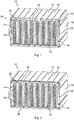
- Fig. 2 schematically represents a perspective front view of the electric device 10 where the two transverse members 28 of the locking arrangement 16 have been removed.
- each back plate 22 comprises two grip features 36.
- the grip features 36 are covered by the transverse members 28 when the transverse members 28 are connected between the side members 26.
- one grip feature 36 is arranged adjacent to the top wall 20 and one grip feature 36 is arranged adjacent to the bottom wall.
- each grip feature 36 is a recess for receiving human fingers.
- each cable to the electric contacts 24 can be maintained connected.
- the transverse members 28 are again connected to the side members 26 to form the frame illustrated in Fig. 1 by means of the snap-fit connection of the locking mechanisms 34. No tools are required for this.
- Fig. 3 schematically represents a perspective front view of the electric device 10 in a case where all electric module cards 14 have been removed.
- the bottom wall 38 and the space 40 defined between the two side walls 18 and the bottom wall 38 can be seen.
- the bottom wall 38 can be seen in Fig. 3 .
- the top wall 20 spans between a top of each side wall 18 and the bottom wall 38 spans between a bottom of each side wall 18.
- Fig. 4 schematically represents a partial perspective front view of the locking arrangement 16
- Fig. 5 schematically represents a partial perspective front view of the locking arrangement 16 where the transverse member 28 has been detached from the side member 26.
- the locking mechanism 34 comprises a flexible locking element 42, here exemplified as a tongue.
- the locking element 42 comprises a hook 44 at a distal end thereof.
- the locking mechanism 34 further comprises a hole 46 and a wedge 48 inside the hole 46.
- the locking mechanism 34 further comprises an optional guiding pin 50 and an aperture (not shown) for receiving the guiding pin 50.
- the hole 46 and wedge 48 are provided on the transverse member 28.
- the locking element 42 and the guiding pin 50 are provided on the side member 26.
- the transverse member 28 In order to connect the transverse member 28 to the side member 26 by means of the snap-fit of the locking mechanism 34, the transverse member 28 is moved to the side member 26 such that the locking element 42 enters the hole 46 until the hook 44 snaps over the wedge 48 (and such that the guiding pin 50 enters the aperture). In this state, as illustrated in Fig. 4 , the locking element 42 protrudes out from the hole 46 and is thereby accessible for a human finger. By means of a slight push on the locking element 42, the engagement between the hook 44 and the wedge 48 can be released and the transverse member 28 can be detached from the side member 26.
- the locking mechanism 34 enable a toolless connection and disconnection of the transverse member 28 to and from the side member 26.
- the hole 46 also provides access for a flat-bladed screw driver or other tool that can be inserted into the hole 46 and turned in order to release the snap-fit of the locking mechanism 34.
- a flat-bladed screw driver or other tool that can be inserted into the hole 46 and turned in order to release the snap-fit of the locking mechanism 34.
- Figs. 4 and 5 one of the screw holes 52 for the screw 30 is also shown.
- Fig. 6 schematically represents a partial perspective front view of an alternative locking arrangement
- Fig. 7 schematically represents a partial perspective front view of the locking arrangement 16 in Fig. 6 where the transverse member 28 has been detached from the side member 26,
- Fig. 8 schematically represents a further partial perspective front view of the locking arrangement 16 in Fig. 7 .
- the locking element 42 and the hole 46 are provided on the transverse member 28 and the wedge 48 is provided on the side member 26.
- the locking element 42 is arranged at an exterior part of the transverse member 28.
- the locking element 42 is thereby accessible for a human finger on the side of the side member 26.
- the locking mechanism 34 in Figs. 6-8 enables toolless handling.
- a tool such as a flat-bladed screw drive, can be inserted into the hole 46 and be twisted to release the snap-fit.
Landscapes
- Engineering & Computer Science (AREA)
- Microelectronics & Electronic Packaging (AREA)
- Casings For Electric Apparatus (AREA)
- Mounting Of Printed Circuit Boards And The Like (AREA)
Priority Applications (7)
| Application Number | Priority Date | Filing Date | Title |
|---|---|---|---|
| EP20154894.8A EP3860320A1 (fr) | 2020-01-31 | 2020-01-31 | Agencement de verrouillage pour cartes de module électrique, boîtier et dispositif électrique |
| US17/791,610 US11638361B2 (en) | 2020-01-31 | 2021-01-13 | Locking mechanism for module cards for grid automations products |
| EP21700305.2A EP4098087B1 (fr) | 2020-01-31 | 2021-01-13 | Agencement de verrouillage pour cartes de module électrique, boîtier et dispositif électrique |
| JP2022546548A JP7253673B2 (ja) | 2020-01-31 | 2021-01-13 | 電気モジュールカードのためのロック構成、筐体、および電気装置 |
| FIEP21700305.2T FI4098087T3 (fi) | 2020-01-31 | 2021-01-13 | Lukitusjärjestely sähköisille moduulikorteille, kotelo ja sähkölaite |
| CN202180008376.5A CN114930995B (zh) | 2020-01-31 | 2021-01-13 | 用于电气模块卡的锁定装置、壳体和电气设备 |
| PCT/EP2021/050548 WO2021151666A1 (fr) | 2020-01-31 | 2021-01-13 | Système de verrouillage pour cartes de module électrique, boîtier et dispositif électrique |
Applications Claiming Priority (1)
| Application Number | Priority Date | Filing Date | Title |
|---|---|---|---|
| EP20154894.8A EP3860320A1 (fr) | 2020-01-31 | 2020-01-31 | Agencement de verrouillage pour cartes de module électrique, boîtier et dispositif électrique |
Publications (1)
| Publication Number | Publication Date |
|---|---|
| EP3860320A1 true EP3860320A1 (fr) | 2021-08-04 |
Family
ID=69423179
Family Applications (2)
| Application Number | Title | Priority Date | Filing Date |
|---|---|---|---|
| EP20154894.8A Withdrawn EP3860320A1 (fr) | 2020-01-31 | 2020-01-31 | Agencement de verrouillage pour cartes de module électrique, boîtier et dispositif électrique |
| EP21700305.2A Active EP4098087B1 (fr) | 2020-01-31 | 2021-01-13 | Agencement de verrouillage pour cartes de module électrique, boîtier et dispositif électrique |
Family Applications After (1)
| Application Number | Title | Priority Date | Filing Date |
|---|---|---|---|
| EP21700305.2A Active EP4098087B1 (fr) | 2020-01-31 | 2021-01-13 | Agencement de verrouillage pour cartes de module électrique, boîtier et dispositif électrique |
Country Status (6)
| Country | Link |
|---|---|
| US (1) | US11638361B2 (fr) |
| EP (2) | EP3860320A1 (fr) |
| JP (1) | JP7253673B2 (fr) |
| CN (1) | CN114930995B (fr) |
| FI (1) | FI4098087T3 (fr) |
| WO (1) | WO2021151666A1 (fr) |
Citations (4)
| Publication number | Priority date | Publication date | Assignee | Title |
|---|---|---|---|---|
| CH667959A5 (en) * | 1985-07-26 | 1988-11-15 | Contraves Ag | Housing frame for electronic rack mounted circuit boards - has hinged front carrier unit that retains modules and provides handles for carrying |
| US5317483A (en) * | 1993-01-26 | 1994-05-31 | Dell U.S.A., L.P. | Computer expansion card support structure |
| US20070090268A1 (en) * | 2005-09-30 | 2007-04-26 | Hon Hai Precision Industry Co., Ltd. | Positioning apparatus for test fixtures |
| US20110008103A1 (en) * | 2009-07-13 | 2011-01-13 | Hong Fu Jin Precision Industry (Shenzhen) Co., Ltd. | Expansion card retention assembly |
Family Cites Families (19)
| Publication number | Priority date | Publication date | Assignee | Title |
|---|---|---|---|---|
| US4155109A (en) * | 1977-12-19 | 1979-05-15 | International Business Machines Corporation | Planar board and card-on-board electronic package assembly |
| DE2757761A1 (de) | 1977-12-23 | 1979-06-28 | Siemens Ag | Baugruppentraeger fuer elektronische baugruppen |
| JPS5874385U (ja) * | 1981-11-16 | 1983-05-19 | 日本電気株式会社 | プリント基板の抜け防止構造 |
| JPS60106390U (ja) * | 1983-12-22 | 1985-07-19 | 日本電気株式会社 | パツケ−ジ押え機構 |
| JPS63115286U (fr) * | 1987-01-22 | 1988-07-25 | ||
| DE9412285U1 (de) | 1994-07-29 | 1994-10-06 | Interplast GmbH, 88367 Hohentengen | Gehäusesystem |
| US6349039B1 (en) * | 1997-09-10 | 2002-02-19 | Micron Technology, Inc. | Apparatus for coupling computer components |
| US7039291B1 (en) * | 2001-02-21 | 2006-05-02 | Joseph Georgiano | Card rack |
| US20030052578A1 (en) * | 2001-09-17 | 2003-03-20 | Kuo-Chuan Hung | Pivot axis of an industrial computer door guard |
| US7075796B1 (en) * | 2005-09-06 | 2006-07-11 | Hewlett-Packard Development Company, L.P. | Cage for printed circuit board |
| TWM318239U (en) | 2007-01-02 | 2007-09-01 | Hon Hai Prec Ind Co Ltd | Electrical card connector |
| TWM331272U (en) * | 2007-05-10 | 2008-04-21 | Lite On Technology Corp | Fastening apparatus |
| EP2077704B1 (fr) * | 2008-01-07 | 2012-06-20 | Schroff GmbH | Module électronique enfichable destiné à la réception dans un support de composants |
| CN102144434B (zh) * | 2008-09-04 | 2014-08-20 | Sk新技术 | 多层印刷电路板固定结构体 |
| CN201319169Y (zh) * | 2008-11-17 | 2009-09-30 | 鸿富锦精密工业(深圳)有限公司 | 卡板固定结构 |
| CN201628898U (zh) | 2009-10-29 | 2010-11-10 | 鸿富锦精密工业(深圳)有限公司 | 扩充卡固定装置 |
| DE102010060722B4 (de) | 2010-11-22 | 2020-04-02 | Paul Hettich Gmbh & Co. Kg | Verbindungsbeschlag |
| JP5874385B2 (ja) | 2011-12-26 | 2016-03-02 | コニカミノルタ株式会社 | 画像形成装置、画像形成方法及びプログラム |
| US9801296B1 (en) * | 2017-01-16 | 2017-10-24 | Dinkle Enterprise Co., Ltd. | Housing device having pull-type locking and release structure |
-
2020
- 2020-01-31 EP EP20154894.8A patent/EP3860320A1/fr not_active Withdrawn
-
2021
- 2021-01-13 WO PCT/EP2021/050548 patent/WO2021151666A1/fr unknown
- 2021-01-13 JP JP2022546548A patent/JP7253673B2/ja active Active
- 2021-01-13 FI FIEP21700305.2T patent/FI4098087T3/fi active
- 2021-01-13 EP EP21700305.2A patent/EP4098087B1/fr active Active
- 2021-01-13 US US17/791,610 patent/US11638361B2/en active Active
- 2021-01-13 CN CN202180008376.5A patent/CN114930995B/zh active Active
Patent Citations (4)
| Publication number | Priority date | Publication date | Assignee | Title |
|---|---|---|---|---|
| CH667959A5 (en) * | 1985-07-26 | 1988-11-15 | Contraves Ag | Housing frame for electronic rack mounted circuit boards - has hinged front carrier unit that retains modules and provides handles for carrying |
| US5317483A (en) * | 1993-01-26 | 1994-05-31 | Dell U.S.A., L.P. | Computer expansion card support structure |
| US20070090268A1 (en) * | 2005-09-30 | 2007-04-26 | Hon Hai Precision Industry Co., Ltd. | Positioning apparatus for test fixtures |
| US20110008103A1 (en) * | 2009-07-13 | 2011-01-13 | Hong Fu Jin Precision Industry (Shenzhen) Co., Ltd. | Expansion card retention assembly |
Also Published As
| Publication number | Publication date |
|---|---|
| JP2023507232A (ja) | 2023-02-21 |
| EP4098087A1 (fr) | 2022-12-07 |
| US20230040890A1 (en) | 2023-02-09 |
| CN114930995B (zh) | 2023-11-10 |
| EP4098087B1 (fr) | 2024-06-05 |
| WO2021151666A1 (fr) | 2021-08-05 |
| CN114930995A (zh) | 2022-08-19 |
| JP7253673B2 (ja) | 2023-04-06 |
| FI4098087T3 (fi) | 2024-07-22 |
| US11638361B2 (en) | 2023-04-25 |
Similar Documents
| Publication | Publication Date | Title |
|---|---|---|
| CA2522256C (fr) | Montage de boitier avec au moins une boite de jonction | |
| US20070246256A1 (en) | Electronics housing | |
| US6865078B1 (en) | Server radiator | |
| US5726852A (en) | Modular DC distribution unit and system | |
| JP5688627B2 (ja) | 回路遮断器 | |
| US10368458B2 (en) | Rail-mounted control system with improved mounting | |
| US8625748B2 (en) | Removable sensor modules | |
| US20130040494A1 (en) | Supply module and drive module | |
| JP2008533965A (ja) | 配電盤装置若しくはラック装置 | |
| CA1069207A (fr) | Carte de modules qu'on peut retirer facilement | |
| EP3860320A1 (fr) | Agencement de verrouillage pour cartes de module électrique, boîtier et dispositif électrique | |
| JP2006513547A (ja) | モジュール式取付け装置 | |
| CA2289145C (fr) | Ensemble de bornes munies de vis de blocage resistantes aux vibrations | |
| US9755332B1 (en) | Terminal blocks | |
| CA2935842A1 (fr) | Panneau modulaire sans porte | |
| US6275126B1 (en) | Molded case power switch with secondary cover removably secured by quick release fasteners | |
| Cisco | Repair and Replacement | |
| Cisco | Repair and Replacement | |
| Cisco | Repair & Replacement | |
| US11705602B2 (en) | Battery pack having interlock structure | |
| Cisco | Replacement | |
| Cisco | Repair and Replacement | |
| Cisco | Repair and Replacement | |
| Cisco | Enclosure and Card Installation | |
| WO2002039756A1 (fr) | Raccord et/ou panneau test monte en rattrapage |
Legal Events
| Date | Code | Title | Description |
|---|---|---|---|
| PUAI | Public reference made under article 153(3) epc to a published international application that has entered the european phase |
Free format text: ORIGINAL CODE: 0009012 |
|
| STAA | Information on the status of an ep patent application or granted ep patent |
Free format text: STATUS: THE APPLICATION HAS BEEN PUBLISHED |
|
| AK | Designated contracting states |
Kind code of ref document: A1 Designated state(s): AL AT BE BG CH CY CZ DE DK EE ES FI FR GB GR HR HU IE IS IT LI LT LU LV MC MK MT NL NO PL PT RO RS SE SI SK SM TR |
|
| RAP3 | Party data changed (applicant data changed or rights of an application transferred) |
Owner name: HITACHI ENERGY SWITZERLAND AG |
|
| STAA | Information on the status of an ep patent application or granted ep patent |
Free format text: STATUS: THE APPLICATION IS DEEMED TO BE WITHDRAWN |
|
| 18D | Application deemed to be withdrawn |
Effective date: 20220205 |