EP3859943A1 - Magnetsystem für einen rotor und elektrische permanentmagnetmaschine - Google Patents
Magnetsystem für einen rotor und elektrische permanentmagnetmaschine Download PDFInfo
- Publication number
- EP3859943A1 EP3859943A1 EP20155136.3A EP20155136A EP3859943A1 EP 3859943 A1 EP3859943 A1 EP 3859943A1 EP 20155136 A EP20155136 A EP 20155136A EP 3859943 A1 EP3859943 A1 EP 3859943A1
- Authority
- EP
- European Patent Office
- Prior art keywords
- support member
- magnet
- protrusion
- recess
- axial direction
- Prior art date
- Legal status (The legal status is an assumption and is not a legal conclusion. Google has not performed a legal analysis and makes no representation as to the accuracy of the status listed.)
- Withdrawn
Links
Images


Classifications
-
- H—ELECTRICITY
- H02—GENERATION; CONVERSION OR DISTRIBUTION OF ELECTRIC POWER
- H02K—DYNAMO-ELECTRIC MACHINES
- H02K1/00—Details of the magnetic circuit
- H02K1/06—Details of the magnetic circuit characterised by the shape, form or construction
- H02K1/22—Rotating parts of the magnetic circuit
- H02K1/27—Rotor cores with permanent magnets
- H02K1/2786—Outer rotors
- H02K1/2787—Outer rotors the magnetisation axis of the magnets being perpendicular to the rotor axis
- H02K1/2789—Outer rotors the magnetisation axis of the magnets being perpendicular to the rotor axis the rotor consisting of two or more circumferentially positioned magnets
- H02K1/2791—Surface mounted magnets; Inset magnets
-
- F—MECHANICAL ENGINEERING; LIGHTING; HEATING; WEAPONS; BLASTING
- F03—MACHINES OR ENGINES FOR LIQUIDS; WIND, SPRING, OR WEIGHT MOTORS; PRODUCING MECHANICAL POWER OR A REACTIVE PROPULSIVE THRUST, NOT OTHERWISE PROVIDED FOR
- F03D—WIND MOTORS
- F03D9/00—Adaptations of wind motors for special use; Combinations of wind motors with apparatus driven thereby; Wind motors specially adapted for installation in particular locations
- F03D9/20—Wind motors characterised by the driven apparatus
- F03D9/25—Wind motors characterised by the driven apparatus the apparatus being an electrical generator
-
- H—ELECTRICITY
- H02—GENERATION; CONVERSION OR DISTRIBUTION OF ELECTRIC POWER
- H02K—DYNAMO-ELECTRIC MACHINES
- H02K1/00—Details of the magnetic circuit
- H02K1/06—Details of the magnetic circuit characterised by the shape, form or construction
- H02K1/22—Rotating parts of the magnetic circuit
- H02K1/27—Rotor cores with permanent magnets
- H02K1/2706—Inner rotors
- H02K1/272—Inner rotors the magnetisation axis of the magnets being perpendicular to the rotor axis
- H02K1/274—Inner rotors the magnetisation axis of the magnets being perpendicular to the rotor axis the rotor consisting of two or more circumferentially positioned magnets
- H02K1/2753—Inner rotors the magnetisation axis of the magnets being perpendicular to the rotor axis the rotor consisting of two or more circumferentially positioned magnets the rotor consisting of magnets or groups of magnets arranged with alternating polarity
- H02K1/278—Surface mounted magnets; Inset magnets
-
- H—ELECTRICITY
- H02—GENERATION; CONVERSION OR DISTRIBUTION OF ELECTRIC POWER
- H02K—DYNAMO-ELECTRIC MACHINES
- H02K7/00—Arrangements for handling mechanical energy structurally associated with dynamo-electric machines, e.g. structural association with mechanical driving motors or auxiliary dynamo-electric machines
- H02K7/18—Structural association of electric generators with mechanical driving motors, e.g. with turbines
- H02K7/1807—Rotary generators
- H02K7/1823—Rotary generators structurally associated with turbines or similar engines
- H02K7/183—Rotary generators structurally associated with turbines or similar engines wherein the turbine is a wind turbine
-
- F—MECHANICAL ENGINEERING; LIGHTING; HEATING; WEAPONS; BLASTING
- F05—INDEXING SCHEMES RELATING TO ENGINES OR PUMPS IN VARIOUS SUBCLASSES OF CLASSES F01-F04
- F05D—INDEXING SCHEME FOR ASPECTS RELATING TO NON-POSITIVE-DISPLACEMENT MACHINES OR ENGINES, GAS-TURBINES OR JET-PROPULSION PLANTS
- F05D2220/00—Application
- F05D2220/70—Application in combination with
- F05D2220/76—Application in combination with an electrical generator
-
- H—ELECTRICITY
- H02—GENERATION; CONVERSION OR DISTRIBUTION OF ELECTRIC POWER
- H02K—DYNAMO-ELECTRIC MACHINES
- H02K2213/00—Specific aspects, not otherwise provided for and not covered by codes H02K2201/00 - H02K2211/00
- H02K2213/12—Machines characterised by the modularity of some components
-
- Y—GENERAL TAGGING OF NEW TECHNOLOGICAL DEVELOPMENTS; GENERAL TAGGING OF CROSS-SECTIONAL TECHNOLOGIES SPANNING OVER SEVERAL SECTIONS OF THE IPC; TECHNICAL SUBJECTS COVERED BY FORMER USPC CROSS-REFERENCE ART COLLECTIONS [XRACs] AND DIGESTS
- Y02—TECHNOLOGIES OR APPLICATIONS FOR MITIGATION OR ADAPTATION AGAINST CLIMATE CHANGE
- Y02E—REDUCTION OF GREENHOUSE GAS [GHG] EMISSIONS, RELATED TO ENERGY GENERATION, TRANSMISSION OR DISTRIBUTION
- Y02E10/00—Energy generation through renewable energy sources
- Y02E10/70—Wind energy
- Y02E10/72—Wind turbines with rotation axis in wind direction
Definitions
- the present invention relates to a magnet system for a rotor of a permanent magnet electrical machine, relates to a rotor for a permanent magnet electrical machine and further relates to a permanent magnet electrical machine including the rotor.
- a permanent magnet electrical machine comprises an inner or outer rotor at which magnet modules are mounted.
- the magnet modules may be slid into machined slots (or rails or tracks) on the inside of the rotor house. When they are assembled, each of the modules forms a magnetic pole.
- the slots may run from the non-drive end (NDE) to the drive end (DE) of the rotor house. The slots can go straight (axially, along the axis of rotation) or can be skewed.
- the slot may be designed to be wider than the width of the base of the magnet modules (also referred to as base plate).
- the magnet modules and the machined slot are designed and machined to have relative tolerances. Tolerance gaps between the magnet modules on one hand and the walls of the tracks or slots are required to allow the magnet modules to easily slide along the rotor groove. These tolerance gaps may lead to movement of the magnet modules during the operation. This may cause damage of the magnet modules or/and the rotor house as well as may result in access noise and vibration.
- the magnet modules can, during operation, move tangentially (i.e. in the circumferential direction) from one slot wall to the other slot wall, depending on the forces acting on it.
- tangential movement of some of the magnet modules may occur in full operation or in partially open circuit modes (i.e. reduced converter operation (RCO)) and when running at low loads.
- RCO reduced converter operation
- fractional slot topologies where the number of poles does not divide into the number of slots without giving a remainder.
- the fraction of poles and slots is not equal to an integer. For example, in a 12 slots 10 poles configuration, the tangential force in open circuit operation on a single pole varies over an electrical cycle from a positive value to a negative value (open circuit operation is when the generator is not connected to any external electrical circuit). Thereby, a possible movement of the magnet module in the rotor slots (depending on the coefficient of friction) may result.
- the magnets In permanent magnet machines with in particular surface-mounted magnets, tangential forces act on the magnets during operation.
- the magnets are often fixed in a slot (or rail or track) that runs in the axle direction of the rotor.
- the slots of the rotor are slightly wider than the magnets/magnet modules. Due to this difference of the width of the magnet module and the slot, the magnet may slide from one side of the slot to the other side of the slot depending on the forces between the stator teeth and the magnet.
- the magnet module may consist of a magnet fixed to a base plate.
- the base plate is the part that may slide from one side to the other side of the slot or rail or track. The sliding from one side to the other side may over time have the effect that the support on the side of the slot might break and that the magnet or the magnet module may come off or do critical damage to the machine.
- the magnet modules are held by friction forces.
- slight movements of the magnet modules might occur during operation resulting in the risk of damage and/or wear and resulting also in excessive noise and vibration.
- a problem occurred with a permanent magnet electrical machine which comprises two, three, four or even more stator segments, wherein electrical windings of each stator segment is connected to an individual converter. If these kinds of electrical machine are run in reduced converter operation (meaning that at least one stator segment is not operational), increased risk of movement of magnet modules may result.
- a magnet system for a rotor of a permanent magnet electrical machine comprising: a first (e.g. magnet) module comprising a first support member; a second (e.g. magnet) module comprising a second support member; wherein the first module comprises a first permanent magnet supported by the first support member and/or the second module comprises a second permanent magnet supported by the second support member, wherein the first support member and the second support member have respective contact portions (e.g. interlocking/engaging/locking portions) which are at least partly structurally complementary to each other allowing to arrange the first module and the second module adjacent to each other in the axial direction (e.g. such that axial side edges contact each other), while the contact portions contact each other and causing traverse shift in a direction travers to the axial direction (in particular the circumferential direction), when pushed towards each other in the axial direction.
- a first (e.g. magnet) module comprising a first support member
- a second (e.g. magnet) module comprising a second support
- the rotor may be an outer rotor or an inner rotor.
- the magnets may be mounted at an inside face or an outside face of the rotor.
- the first support member and/or the second support member may be configured for supporting a respective permanent magnet.
- the respective magnets may be mounted in a conventional manner to the respective support member.
- the magnet may be mounted or fixed to the support member e.g. by gluing (e.g. applying glue at a support surface of the support member and pressing the magnet onto it), dovetail lock, moulding etc.
- a cover surrounding the magnet may be welded to the support member to protect the magnet.
- the first support member as well as the second support member may have a substantially rectangular shape when the contact portions are disregarded. The contact portion however may protrude in particular in the axial direction from the substantially rectangular shaped support members or may comprise as a complementary structure a recess in the axial direction.
- At least one or both of the first and second modules may comprise a respective permanent magnet.
- the magnet system may comprise more than two modules, such as three, four, five, six, seven or even more than seven or more than ten modules.
- the modules may be lined up in the axial direction adjacent to each other.
- the axial direction corresponds to the axial direction of the permanent magnet electrical machine comprising a rotor having at least one magnet system.
- Plural magnet systems may be provided spaced apart in the circumferential direction of the rotor and mounted thereto, in particular using slots or rails or tracks into which the respective magnet modules are slid along the axial direction. In particular, all the magnet modules may be slid in towards an axial stop member and may then contact each other at respective axial ends.
- a pressure in the axial direction may be applied at the end of the chain of magnet modules thereby resulting in that the contact portions of adjacent magnet modules contact each other and exert traverse forces onto each other in a direction traverse to the axial direction, in order to push the magnet module in particular in the tangential direction or substantially in the tangential direction to be in close contact with a wall section of a slot or a track or a rail.
- tangential movement of the magnet modules may be reduced or even be avoided.
- the contact portions of adjacent modules may partially at least slide along each other at respective straight edges which may be tapered or slanted relative to or in comparison to the axial direction. Or, for example, the contact portion or at least contact edges may have at least partly a wedge shape.
- the contact portions may be configured to interlock and/or engage and/or lock with each other.
- Structurally complementary may mean that one of the contact portions, for example the contact portion of the first module, comprises a structure in a particular shape, wherein the second contact portion of the second module comprises a cavity or a recess of a substantially same geometrical shape.
- either the entire respective module or at least the side or edge at which the respective contact portion is provided may traversely shift or move in a direction traverse to the axial direction (in particular perpendicular to the axial direction which corresponds to the circumferential direction of the rotor).
- the edge of the respective module or the entire module may be pressed onto a circumferential wall section of a rail or a track or a slot and thereby hampering or prohibiting tangential, i.e. circumferential, movement during operation.
- the respective support members may be configured as base plate having substantially a rectangular shape.
- the support member may have a larger thickness in an area where the respective magnet is to be mounted and may have in a marginal region a lower thickness.
- a metal cover or metal cap may be provided above the magnet for protecting the magnet.
- the cap or cover (in particular metal cover) may be welded at the base plate for example.
- each support member is arranged close to a side edge of the respective support member and/or at an axial end and/or wherein the contact portion is integrally formed with the respective support member.
- the contact portion When the contact portion is close to a side edge (for example running in the axial direction), the manufacturing may be simplified.
- the contact portion may either protrude or be recessed relative to a respective axial end of the respective support member.
- the contact portion of the first support member is arranged at an axial end of the first support member, wherein the first support member has another contact portion at another axial end, and/or wherein the contact portion of the second support member is arranged at an axial end of the second support member, wherein the second support member has another contact portion at another axial end.
- plural magnet modules may be lined up in the axial direction and may be pushed in a direction traverse to the axial direction when pressed against each other in the axial direction.
- all magnet modules in the chain of adjacent magnet modules may forcibly be pushed towards one side (wall) of a rail or track or slot which is provided for inserting the magnet modules in the axial direction.
- One module may interact with (contact) two other modules, one at the axial end and the other at the other axial end of the considered magnet module.
- either respective modules having only one contact portion at an axial side facing an adjacent magnet module may be provided.
- end plates for example support members without having a magnet mounted, may be provided which may have a respective contact portion only at one axial end.
- the contact portion and/or the other contact portion of the first support member comprises a, in particular tapered, protrusion protruding in the axial direction (e.g. from the axial end or the other axial end), wherein the contact portion and/or the other contact portion of the second support member is formed by a, in particular tapered, recess recessed in the axial direction.
- the recess may be complementary to the protrusion or the recess of the second support member may be complementary in shape to the protrusion of the first contact portion of the first support member.
- the protrusion may at least partly or completely fill a space formed by the recess when the first and the second modules are lined up in the axial direction and when they are pushed towards each other in the axial direction.
- the contact portions are implemented in a simple manner.
- the protrusion may in particular comprise at least one slanted edge or surface allowing to slide the protrusion into the recess thereby causing a traverse force on the support member with which the protrusion is in contact.
- the protrusion partly deforms when pushed along the axial direction into the recess.
- the interlocking or engaging between the protrusion and the recess may be enforced providing additional holding forces, for example clamping forces similar to a press-fit. Thereby, the stability of the mounted modules may be improved.
- the protrusion and material limiting the recess have complementary sliding surfaces tilted relative to the axial direction (but e.g. being at a constant radial position), thereby engaging in a wedge like manner and/or wherein the protrusion and the recess are shaped such that when the protrusion is entirely inserted into the recess, (in particular straight) edges (e.g. at the axial or the other axial end) of the first support member and the second support member contact each other.
- the sliding surfaces may allow to slide the contact portion of the first magnet module with respect to the contact portion of the second magnet module.
- the sliding surfaces may in particular be or comprise straight edges or surfaces or plane surfaces.
- the tilt angle relative to the axial direction may for example be between 1° and 45°. Other angles are possible.
- edges of the first support member and the second support member contact each other, the magnets may be mounted very close to each other as may be desired depending on the application.
- the protrusion and/or the recess has trapezoid shape or triangular shape or tapered rectangular shape.
- the protrusion and/or the recess is over the whole thickness or over only a part of the thickness of the respective support member.
- manufacturing may be simplified.
- the protrusion and/or the recess is over only a part of the thickness of the respective support member, it may be enabled that the contact portions are also provided in a portion of the respective support member beneath or below a magnet.
- the area of the respective contact portions in particular the contact area with an adjacent contact portion, may be increased thereby also possibly increasing the traverse force generated by the two contact portions contacting and pressing to each other in the axial direction.
- the recess may for example have a triangular shape, wherein about a half of the thickness of the support member may be removed or may be missing.
- the protrusion may for example then have a trapezoid shape or also a triangular shape.
- the protrusion and/or the recess has an extent in axial direction of the support member of between 0.1 and 0.2 of an axial extent of the support member and/or the first support member and/or the second support member is essentially configured as metal base plate, in particular essentially rectangular.
- the axial extent and also the slanting or tilt angle relative to the axial direction may be appropriately adjusted.
- a substantially rectangular base plate is utilized as a respective support member, conventionally available parts may be utilized in embodiments of the present invention.
- the first support member and/or the second support have essentially the same shape; the first support member and/or the second support have the same shape and 180° rotation symmetry; the first support member and/or the second support have different shapes; the first support member and/or the second support have a mirror symmetry.
- the first support member as well as the second support member both have a recess and a protrusion at different axial ends.
- the first support member has a protrusion at both axial ends and the second support member has two recesses at two axial ends.
- the first as well as the second support member have at a first axial side a protrusion and a recess and also have on a second axial side a protrusion and a recess.
- the first support member and/or the second support has a protrusion as well as a recess or the first support member and/or the second support has only at least one protrusion but no recess or wherein the first support member and/or the second support has no protrusion but only at least one recess.
- the first support member has protrusions at both axial ends (e.g. close to a circumferential edge)
- a force acting in the same traverse direction may act when this support member is sandwiched between two adjacent support members each having at the contacting axial edge a respective recess.
- the central support member may then be pushed towards this circumferential side close to which the protrusions are provided.
- this configuration may result in a parallel shift or parallel force acting traverse, in particular perpendicular to the axial direction.
- the first support member when it comprises at a first axial end a recess and at a second axial end a protrusion, it may be pushed at the first axial end by a traverse force acting substantially in the opposite direction than the traverse force acting at the second axial end.
- the respective first support member may slightly be tilted (turned) relative to the axial direction when inserted and pressed from neighbouring support members in the axial direction.
- a rotor for a permanent magnet electrical machine comprising: a rotor yoke comprising plural axially extending rails (e.g. tracks); a magnet system according to one of the precedingly described embodiments inserted between a first rail and a second rail spaced apart in the circumferential direction in the axial direction to push against a first axial stop and clamped between the first axial stop and a second axial stop.
- a rotor for a permanent magnet electrical machine comprising: a rotor yoke comprising plural axially extending rails (e.g. tracks); a magnet system according to one of the precedingly described embodiments inserted between a first rail and a second rail spaced apart in the circumferential direction in the axial direction to push against a first axial stop and clamped between the first axial stop and a second axial stop.
- the rotor may be an outer rotor or an inner rotor.
- the rotor may for example comprise 10 to 30 magnet systems as have been described above.
- Each magnet system may for example comprise between 5 and 10 or 5 and 20 magnet modules which are lined up in the axial direction.
- the rail may for example have a T-shaped cross-section in a cross-section perpendicular to the axial direction.
- each rail may have a T-shape.
- the margin of the respective support members may be slid under the head of the "T".
- a respective magnet module may be slid into a track formed by two circumferentially spaced apart rails.
- the stem part of the "T" may form a circumferential limiting wall for the respective support member.
- the support member may either be pressed towards the first rail or the second rail, in particular the respective circumferential wall portion of the rail.
- the first axial stop and/or the second axial stop may be configured as end plates for example, having for example only on one axial side a respective contact portion similar or same as the contact portion of the respective support members.
- the magnet system is inserted into the two adjacent rails such that (a first circumferential side edge of or a portion thereof) the first support member is in contact with (e.g. pressed towards) the first rail and the second support member (or a portion thereof) is in contact with (e.g. pressed towards) the second rail.
- a secure and fixed mounting of the magnet may be achieved.
- a permanent magnet electrical machine comprising: a stator; and a rotor according to the precedingly described embodiment.
- the permanent magnet electrical machine may be utilized in a wind turbine according to an embodiment of the present invention.
- the permanent magnet electrical machine may in particular comprise a whole stator or several stator segments, for example two, three, four, five or even more stator segments.
- Each stator segment or the complete stator may be connected to a respective converter, in particular AD-DC-AD converter.
- the permanent magnet electrical machine may be configured also to be operated in partial mode, wherein not all of the stator segments are operational.
- the rotor 150 schematically illustrated in Fig. 1 in a cross-sectional view sectioned perpendicular to an axial direction 101 comprises a rotor yoke 103 comprising plural axially extending rails 105, 107.
- the rotor 150 further comprises at least one magnet system 100 according to an embodiment of the present invention which is inserted between a first rail 105 and a second rail 107 which are spaced apart in the circumferential direction 109.
- the magnet system 100 is inserted in the axial direction 101 between the first rail 105 and the second rail 107.
- the magnet system 100 comprises plural magnet modules (for example magnet modules 310a, 310b, 310c, 310d, 310e) as is illustrated in Fig. 3 in a view along the radial direction 311 which is indicated with reference sign 111 in Fig. 1 .
- the rotor 150 illustrated in Fig. 1 can be utilized in a permanent magnet electrical machine which further comprises a stator inside the rotor 150.
- Fig. 2 schematically illustrates a portion of the rotor 150 illustrated in Fig. 1 which portion is labelled in Fig. 1 with reference sign 117.
- the portion 217 illustrated in Fig. 2 is a cross-sectional illustration seen along the axial direction 201, the circumferential direction is labelled with reference sign 209.
- the first rail 205 has a "T"-shape in the cross-sectional view which also holds for the second rail 207.
- the magnet module 210 comprises a first support member 242 for supporting a first magnet 244.
- the first support member 242 does not have equal thickness over the entire area but comprises a region at which the first magnet 244 is mounted which has a greater thickness than in a border area 246.
- the magnet 244 is mounted at an area where the thickness is greater than in the border or boundary area 246.
- a gap is present which is denoted by reference sign 254.
- the gap may have a size between 0.5 mm and 0.01 mm.
- the gap 254 may allow to easily slide in the magnet module 210 between the first rail 205 and the second rail 207.
- the magnet module 210 may move in the tangential direction 209 which may cause problems.
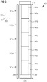
- Fig. 3 schematically illustrates a magnet system 300 in a view along the radial direction 311 comprising six magnet modules 310a, 310b, 310c, 310d, 310e.
- the magnet modules are lined up in the axial direction 301 and are arranged between a first axial stop element 313 and a second axial stop element 315.
- the six magnet modules 310a, ..., 310e are clamped between the first axial stop element 313 and the second axial stop element 315.
- the chain of magnet modules is limited or hold by the first rail 305 and the second rail 307.
- Fig. 4 illustrates, along the radial direction 411, a magnet system 400 according to an embodiment of the present invention comprising a first magnet module 410a and a second magnet module 410b.
- Each of the magnet modules 410a, 410b comprises a respective magnet 444a, 444b mounted on a respective first support member 442a and 442b, respectively.
- the two magnet modules 410a, 410b have a similar construction both comprising a recess 460a and 460b at an axial side and both also comprising a protrusion 470a, 470b.
- the protrusion 470a, 470b is wedge-like or slanted and has a complementary structure or shape complementary to the shape of the recess 460a, 460b.
- first and second magnet modules 410a, 410b When inserted between the two rails (for example illustrated in Fig. 1 or 2 ), the first and second magnet modules 410a, 410b will contact each other with their axial ends 462, 464 and the protrusion 470a will completely or at least partly fill the space provided by the cavity 460b. Thereupon traverse forces 466, 468 are exerted to the first magnet module 410a and to the second magnet module 410b which are opposite to each other. Thereby, the two adjacent magnet modules 410a, 410b will be pushed traverse to the axial direction 401 such as to contact circumferentially limiting rail portions of the first rail 205 and the second rail 207, respectively.
- the contact portions are configured as protrusions and recesses 470, 460 and are arranged close to a side edge (in particular circumferential side edge) of the respective magnet modules.
- the protrusions 470a, 470b are integrally formed with the respective support members 442a, 442b. It is also visible in Fig. 4 that the respective contact portions (implemented by the recesses 460 and the protrusions 470) are provided at two axial ends of the respective support members.
- the protrusion 470a, 470b is tapered which also holds for the recess 460a, 460b.
- Fig. 5 schematically illustrates another magnet system 500 according to an embodiment of the present invention. While the support members 442a, 442b illustrated in Fig. 4 have similar structure or at least similar contact portions, the first support member 542a comprises protrusions 570a, 570b at both axial ends. Further, the second support member 542b comprises recesses 560a and 560b at both axial ends. When pushed against each other in the axial direction 511, the first support member 442a will be pushed by the traverse force 566 (to the right in Fig. 5 ) while the second support member 542b will be pushed by the traverse force 568 (to the left) in Fig. 5 .
- the support members 442a, 442b will be pushed to different rails, for example one to the first rail 205 and the other to the second rail 207 illustrated in Fig. 2 .
- the support member 542a, 542b or in general the magnet module 510a, 510b have a mirror symmetry with respect to a mirror plane running in the plane spanned by the circumferential direction 409 and the radial direction 411.
- Fig. 6 illustrates one magnet module 610a as a part of a magnet system according to an embodiment of the present invention.
- a magnet system may be formed by two or more of the magnet modules 610a illustrated in Fig. 6 .
- the magnet module 610a comprises a recess 660a as well as a protrusion 670a at a first circumferential edge. Further, the magnet module 610a comprises a protrusion 670b and a recess 660b at another circumferential edge. Further, the magnet module 610a has a 180° rotation symmetry around a rotation axis 671 running along the radial direction 611.
- Embodiments of the present invention provide however also a magnet system, wherein contact portions of the respective magnet module are only over a part of the thickness of the respective support member.
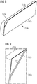
- An example of a magnet system 700 is illustrated in Fig. 7 comprising a first magnet module 710a and a second magnet module 710b.
- the first magnet module 710a comprises a protrusion 770a
- the second magnet module 710b comprises a recess 760b which is then partly filled by the protrusion 770a when the two magnet modules 710a, 710b are arranged close to each other and aligned in the axial direction 701.
- Figs. 8 and 9 illustrate in more detail the second magnet module 710b and Figs. 10 and 11 illustrate in more detail the first magnet module 710a.
- the support member 742b of the second magnet module 710b has the recess 760b at a corner such that the recess is only over a portion of the thickness of the support member 742b. In particular, the recess 760b is even beneath the magnet 744b.
- first magnet module 710a illustrated in Figs. 10 and 11 comprises a protrusion 770a only over a portion of the thickness of the first support member 742a.
- the material limiting the recess 760b provides a sliding surface 772, along which a sliding surface 774 of the protrusion 770a can slide thereby exerting a clamping force.
- the protrusion 770a has a trapezoid shape.
- the recess 760b has a triangular shape.
- the protrusion or tip 470a, 470b, 570a, 570b may be pushed into the space of the removed part (i.e. the recess 460a, 460b, 560a, 560b of the adjacent magnet base plate of support member).
- the removed part of the base plate or support member may be smaller than the protrusion or top so that the tip or protrusion can fill out the removed part plus the difference between the base plate width and the slot width.
- the tip or protrusion can even be deformed and may also thereby act as a lock.
- the dimensions of the removed part and the tip i.e. the dimension of the recess and the protrusion, and adjusting the pressing force there will be no/very little distance between the magnet modules.
- the magnet modules may be pressed against the slot walls (also referred to as rail walls), preventing movement of the magnet/magnet module in the tangential direction in all operating conditions.
- the magnet blocks and the magnet cover may similarly as conventionally known.
- the tilt of the protrusions or recesses is selected such that upon acting an axial force to the magnet modules, the modules will be pushed in a direction traverse to the axial direction, thus towards the walls or sides of the rails or the slot, for example the rails 205 and 207 illustrated in Fig. 2 .
- the axial force may for example be exerted on the magnet module at the NDE of the slot.
- the protrusion may also be described as a conical tip and the recess may be referred to as a cut-out.
- the conical tip and the cut-out may act like one or two wedge(s) and thereby will exert tangential forces at the respective support members for pressing them towards the rail walls, thereby eliminating the gap 254 illustrated in Fig. 2 at one side.
Priority Applications (5)
| Application Number | Priority Date | Filing Date | Title |
|---|---|---|---|
| EP20155136.3A EP3859943A1 (de) | 2020-02-03 | 2020-02-03 | Magnetsystem für einen rotor und elektrische permanentmagnetmaschine |
| EP20824118.2A EP4078772A1 (de) | 2020-02-03 | 2020-11-30 | Magnetsystem für einen rotor und elektrische permanentmagnetmaschine |
| US17/795,957 US20230084226A1 (en) | 2020-02-03 | 2020-11-30 | Magnet system for a rotor and permanent magnet electrical machine |
| CN202080099369.6A CN115298933A (zh) | 2020-02-03 | 2020-11-30 | 用于转子的磁体系统和永磁电机 |
| PCT/EP2020/083904 WO2021155973A1 (en) | 2020-02-03 | 2020-11-30 | Magnet system for a rotor and permanent magnet electrical machine |
Applications Claiming Priority (1)
| Application Number | Priority Date | Filing Date | Title |
|---|---|---|---|
| EP20155136.3A EP3859943A1 (de) | 2020-02-03 | 2020-02-03 | Magnetsystem für einen rotor und elektrische permanentmagnetmaschine |
Publications (1)
| Publication Number | Publication Date |
|---|---|
| EP3859943A1 true EP3859943A1 (de) | 2021-08-04 |
Family
ID=69467411
Family Applications (2)
| Application Number | Title | Priority Date | Filing Date |
|---|---|---|---|
| EP20155136.3A Withdrawn EP3859943A1 (de) | 2020-02-03 | 2020-02-03 | Magnetsystem für einen rotor und elektrische permanentmagnetmaschine |
| EP20824118.2A Pending EP4078772A1 (de) | 2020-02-03 | 2020-11-30 | Magnetsystem für einen rotor und elektrische permanentmagnetmaschine |
Family Applications After (1)
| Application Number | Title | Priority Date | Filing Date |
|---|---|---|---|
| EP20824118.2A Pending EP4078772A1 (de) | 2020-02-03 | 2020-11-30 | Magnetsystem für einen rotor und elektrische permanentmagnetmaschine |
Country Status (4)
| Country | Link |
|---|---|
| US (1) | US20230084226A1 (de) |
| EP (2) | EP3859943A1 (de) |
| CN (1) | CN115298933A (de) |
| WO (1) | WO2021155973A1 (de) |
Citations (4)
| Publication number | Priority date | Publication date | Assignee | Title |
|---|---|---|---|---|
| EP2348619A1 (de) * | 2010-01-20 | 2011-07-27 | Siemens Aktiengesellschaft | Magnetanordnung |
| WO2011091791A2 (de) * | 2010-02-01 | 2011-08-04 | Lloyd Dynamowerke Gmbh & Co. Kg | Befestigungselement zum befestigen eines magneten an einem bauteil einer elektrischen maschine, eine baugruppe sowie bauteil mit einem solchen befestigungselement |
| EP3179605A1 (de) * | 2015-12-08 | 2017-06-14 | ABB Schweiz AG | Rotor für eine elektrische maschine |
| CN110380535A (zh) * | 2019-07-11 | 2019-10-25 | 浙江大学 | 磁极模组、转子屋、转子组件以及永磁电机 |
Family Cites Families (5)
| Publication number | Priority date | Publication date | Assignee | Title |
|---|---|---|---|---|
| DE10215251A1 (de) * | 2002-04-06 | 2003-10-16 | Bosch Gmbh Robert | Elektrische Maschine, insbesondere Permanentmagnet erregte Motore |
| DE102008063045A1 (de) * | 2008-12-23 | 2010-07-01 | Aerodyn Energiesysteme Gmbh | Synchronmaschine |
| CN106849391B (zh) * | 2017-03-06 | 2019-08-02 | 新疆金风科技股份有限公司 | 磁极模块、转子、电机和风力发电机组 |
| CN108777521B (zh) * | 2018-07-27 | 2019-09-06 | 北京金风科创风电设备有限公司 | 磁极模块、电机转子及制造该电机转子的方法 |
| CN111181273B (zh) * | 2019-04-11 | 2021-11-26 | 浙江大学 | 永磁风力发电机的磁极固定装置及永磁风力发电机 |
-
2020
- 2020-02-03 EP EP20155136.3A patent/EP3859943A1/de not_active Withdrawn
- 2020-11-30 US US17/795,957 patent/US20230084226A1/en active Pending
- 2020-11-30 EP EP20824118.2A patent/EP4078772A1/de active Pending
- 2020-11-30 CN CN202080099369.6A patent/CN115298933A/zh active Pending
- 2020-11-30 WO PCT/EP2020/083904 patent/WO2021155973A1/en unknown
Patent Citations (4)
| Publication number | Priority date | Publication date | Assignee | Title |
|---|---|---|---|---|
| EP2348619A1 (de) * | 2010-01-20 | 2011-07-27 | Siemens Aktiengesellschaft | Magnetanordnung |
| WO2011091791A2 (de) * | 2010-02-01 | 2011-08-04 | Lloyd Dynamowerke Gmbh & Co. Kg | Befestigungselement zum befestigen eines magneten an einem bauteil einer elektrischen maschine, eine baugruppe sowie bauteil mit einem solchen befestigungselement |
| EP3179605A1 (de) * | 2015-12-08 | 2017-06-14 | ABB Schweiz AG | Rotor für eine elektrische maschine |
| CN110380535A (zh) * | 2019-07-11 | 2019-10-25 | 浙江大学 | 磁极模组、转子屋、转子组件以及永磁电机 |
Also Published As
| Publication number | Publication date |
|---|---|
| US20230084226A1 (en) | 2023-03-16 |
| CN115298933A (zh) | 2022-11-04 |
| WO2021155973A1 (en) | 2021-08-12 |
| EP4078772A1 (de) | 2022-10-26 |
Similar Documents
| Publication | Publication Date | Title |
|---|---|---|
| US7911104B2 (en) | Pole retention configuration for electric machine rotors | |
| EP1860755B1 (de) | Magnetaufnahmevorrichtung | |
| EP1283581B1 (de) | Läufer für einen Permanentmagnetmotor | |
| US7057322B2 (en) | Rotor for reluctance type rotating machine | |
| AU2011250871B2 (en) | Electric motor and assembly method | |
| EP2216883B1 (de) | Rotor für eine rotierende elektrische maschine | |
| US6548932B1 (en) | Nonmagnetic magnet retention channel arrangement for high speed rotors | |
| JP4793677B2 (ja) | 永久磁石形モータ | |
| EP0569594B1 (de) | Rotor synchroner drehmaschinen | |
| CA2835138C (en) | Low-cost low-cog pm machine | |
| US20090001839A1 (en) | Rotating Electrical Machine | |
| JP2004254496A (ja) | モータ用ロータアセンブリ、モータ用ステータアセンブリ、永久磁石型モータ、およびモータ | |
| WO2007055861A1 (en) | Method of compressing lamination stacks for permanent magnet rotor | |
| US20140117802A1 (en) | Rotor having projections for positioning permanent magnets and electric motor including such rotor | |
| EP2587631A2 (de) | Blechpaket eines Stators für elektrische Maschinen | |
| CN107852047B (zh) | 旋转电机的转子 | |
| EP3859943A1 (de) | Magnetsystem für einen rotor und elektrische permanentmagnetmaschine | |
| CN110912288A (zh) | 单相永磁同步电机及具有其的吸尘器 | |
| CN212486356U (zh) | 转子、内置式永磁电机以及压缩机 | |
| EP2587639A2 (de) | Blechpaket für den Stator einer elektrischen Maschine | |
| US20230179039A1 (en) | Permanent magnet machine | |
| CA2343198A1 (en) | Electric motor rotor | |
| JP4771011B1 (ja) | 回転電機および風力発電システム | |
| CN110034621B (zh) | 旋转电机的转子 | |
| EP4220901A1 (de) | Permanentmagnetmaschine |
Legal Events
| Date | Code | Title | Description |
|---|---|---|---|
| PUAI | Public reference made under article 153(3) epc to a published international application that has entered the european phase |
Free format text: ORIGINAL CODE: 0009012 |
|
| STAA | Information on the status of an ep patent application or granted ep patent |
Free format text: STATUS: THE APPLICATION HAS BEEN PUBLISHED |
|
| AK | Designated contracting states |
Kind code of ref document: A1 Designated state(s): AL AT BE BG CH CY CZ DE DK EE ES FI FR GB GR HR HU IE IS IT LI LT LU LV MC MK MT NL NO PL PT RO RS SE SI SK SM TR |
|
| STAA | Information on the status of an ep patent application or granted ep patent |
Free format text: STATUS: THE APPLICATION IS DEEMED TO BE WITHDRAWN |
|
| 18D | Application deemed to be withdrawn |
Effective date: 20220205 |