EP2348619A1 - Magnetanordnung - Google Patents
Magnetanordnung Download PDFInfo
- Publication number
- EP2348619A1 EP2348619A1 EP10000542A EP10000542A EP2348619A1 EP 2348619 A1 EP2348619 A1 EP 2348619A1 EP 10000542 A EP10000542 A EP 10000542A EP 10000542 A EP10000542 A EP 10000542A EP 2348619 A1 EP2348619 A1 EP 2348619A1
- Authority
- EP
- European Patent Office
- Prior art keywords
- base element
- magnet
- magnet assembly
- rotor
- support structure
- Prior art date
- Legal status (The legal status is an assumption and is not a legal conclusion. Google has not performed a legal analysis and makes no representation as to the accuracy of the status listed.)
- Granted
Links
- 230000000295 complement effect Effects 0.000 claims abstract description 15
- 238000000034 method Methods 0.000 claims abstract description 11
- 230000001681 protective effect Effects 0.000 claims description 15
- 238000004026 adhesive bonding Methods 0.000 claims description 5
- 239000000463 material Substances 0.000 claims description 5
- 239000007769 metal material Substances 0.000 claims description 2
- 230000000712 assembly Effects 0.000 description 12
- 238000000429 assembly Methods 0.000 description 12
- 230000008901 benefit Effects 0.000 description 9
- 230000005291 magnetic effect Effects 0.000 description 7
- 238000004519 manufacturing process Methods 0.000 description 7
- 229910052761 rare earth metal Inorganic materials 0.000 description 3
- 150000002910 rare earth metals Chemical class 0.000 description 3
- 230000005284 excitation Effects 0.000 description 2
- 239000003292 glue Substances 0.000 description 2
- 239000000696 magnetic material Substances 0.000 description 2
- 239000004020 conductor Substances 0.000 description 1
- 230000001419 dependent effect Effects 0.000 description 1
- 238000004870 electrical engineering Methods 0.000 description 1
- 230000005294 ferromagnetic effect Effects 0.000 description 1
- 230000004907 flux Effects 0.000 description 1
- 231100001261 hazardous Toxicity 0.000 description 1
- 238000012423 maintenance Methods 0.000 description 1
- 230000007246 mechanism Effects 0.000 description 1
- 238000010248 power generation Methods 0.000 description 1
- 230000008569 process Effects 0.000 description 1
- 230000004044 response Effects 0.000 description 1
- 238000005476 soldering Methods 0.000 description 1
- 238000003466 welding Methods 0.000 description 1
Images


Classifications
-
- H—ELECTRICITY
- H02—GENERATION; CONVERSION OR DISTRIBUTION OF ELECTRIC POWER
- H02K—DYNAMO-ELECTRIC MACHINES
- H02K1/00—Details of the magnetic circuit
- H02K1/06—Details of the magnetic circuit characterised by the shape, form or construction
- H02K1/22—Rotating parts of the magnetic circuit
- H02K1/27—Rotor cores with permanent magnets
- H02K1/2706—Inner rotors
- H02K1/272—Inner rotors the magnetisation axis of the magnets being perpendicular to the rotor axis
- H02K1/274—Inner rotors the magnetisation axis of the magnets being perpendicular to the rotor axis the rotor consisting of two or more circumferentially positioned magnets
- H02K1/2753—Inner rotors the magnetisation axis of the magnets being perpendicular to the rotor axis the rotor consisting of two or more circumferentially positioned magnets the rotor consisting of magnets or groups of magnets arranged with alternating polarity
- H02K1/278—Surface mounted magnets; Inset magnets
-
- F—MECHANICAL ENGINEERING; LIGHTING; HEATING; WEAPONS; BLASTING
- F03—MACHINES OR ENGINES FOR LIQUIDS; WIND, SPRING, OR WEIGHT MOTORS; PRODUCING MECHANICAL POWER OR A REACTIVE PROPULSIVE THRUST, NOT OTHERWISE PROVIDED FOR
- F03D—WIND MOTORS
- F03D9/00—Adaptations of wind motors for special use; Combinations of wind motors with apparatus driven thereby; Wind motors specially adapted for installation in particular locations
- F03D9/20—Wind motors characterised by the driven apparatus
- F03D9/25—Wind motors characterised by the driven apparatus the apparatus being an electrical generator
-
- H—ELECTRICITY
- H02—GENERATION; CONVERSION OR DISTRIBUTION OF ELECTRIC POWER
- H02K—DYNAMO-ELECTRIC MACHINES
- H02K1/00—Details of the magnetic circuit
- H02K1/06—Details of the magnetic circuit characterised by the shape, form or construction
- H02K1/22—Rotating parts of the magnetic circuit
- H02K1/27—Rotor cores with permanent magnets
- H02K1/2786—Outer rotors
- H02K1/2787—Outer rotors the magnetisation axis of the magnets being perpendicular to the rotor axis
- H02K1/2789—Outer rotors the magnetisation axis of the magnets being perpendicular to the rotor axis the rotor consisting of two or more circumferentially positioned magnets
- H02K1/2791—Surface mounted magnets; Inset magnets
-
- H—ELECTRICITY
- H01—ELECTRIC ELEMENTS
- H01F—MAGNETS; INDUCTANCES; TRANSFORMERS; SELECTION OF MATERIALS FOR THEIR MAGNETIC PROPERTIES
- H01F7/00—Magnets
- H01F7/02—Permanent magnets [PM]
- H01F7/0205—Magnetic circuits with PM in general
- H01F7/0221—Mounting means for PM, supporting, coating, encapsulating PM
-
- H—ELECTRICITY
- H02—GENERATION; CONVERSION OR DISTRIBUTION OF ELECTRIC POWER
- H02K—DYNAMO-ELECTRIC MACHINES
- H02K2213/00—Specific aspects, not otherwise provided for and not covered by codes H02K2201/00 - H02K2211/00
- H02K2213/12—Machines characterised by the modularity of some components
-
- H—ELECTRICITY
- H02—GENERATION; CONVERSION OR DISTRIBUTION OF ELECTRIC POWER
- H02K—DYNAMO-ELECTRIC MACHINES
- H02K7/00—Arrangements for handling mechanical energy structurally associated with dynamo-electric machines, e.g. structural association with mechanical driving motors or auxiliary dynamo-electric machines
- H02K7/18—Structural association of electric generators with mechanical driving motors, e.g. with turbines
- H02K7/1807—Rotary generators
- H02K7/1823—Rotary generators structurally associated with turbines or similar engines
- H02K7/183—Rotary generators structurally associated with turbines or similar engines wherein the turbine is a wind turbine
- H02K7/1838—Generators mounted in a nacelle or similar structure of a horizontal axis wind turbine
-
- Y—GENERAL TAGGING OF NEW TECHNOLOGICAL DEVELOPMENTS; GENERAL TAGGING OF CROSS-SECTIONAL TECHNOLOGIES SPANNING OVER SEVERAL SECTIONS OF THE IPC; TECHNICAL SUBJECTS COVERED BY FORMER USPC CROSS-REFERENCE ART COLLECTIONS [XRACs] AND DIGESTS
- Y02—TECHNOLOGIES OR APPLICATIONS FOR MITIGATION OR ADAPTATION AGAINST CLIMATE CHANGE
- Y02E—REDUCTION OF GREENHOUSE GAS [GHG] EMISSIONS, RELATED TO ENERGY GENERATION, TRANSMISSION OR DISTRIBUTION
- Y02E10/00—Energy generation through renewable energy sources
- Y02E10/70—Wind energy
- Y02E10/72—Wind turbines with rotation axis in wind direction
Definitions
- the present invention relates to the technical field of electromechanical transducers having a rotor which comprises magnets, in particular permanent magnets.
- the present invention relates to a magnet assembly for a rotor arrangement of an electromechanical transducer.
- the present invention relates to a rotor arrangement, to an electromechanical transducer and to a wind turbine, which are all equipped with such a magnet assembly.
- the present invention relates to a method for engaging a magnet assembly with a support structure of a rotor.
- Electromechanical transducers are machines, which convert electrical energy into mechanical energy or vice versa.
- An electric motor is a widely used electromechanical transducer that converts electrical energy into mechanical energy using magnetic field linkage.
- An electric generator is an electromechanical transducer that converts mechanical energy into electrical energy also using a magnetic field linkage.
- An electromechanical transducer comprises a stator and a rotor.
- the stator is an assembly, which represents the stationary part of an electromechanical transducer.
- the rotor is an assembly, which represents the moving part of an electromechanical transducer.
- magnets for instance permanent magnets
- magnets may be used in particular for a rotor of an electromechanical transducer.
- PM electromechanical transducers have become popular since they eliminate the need for commutators and brushes, which are commonly used with conventional Direct Current (DC) electromechanical transducer.
- DC Direct Current
- the absence of an external electrical rotor excitation eliminates losses on the rotor and makes permanent magnet electromechanical transducers more efficient.
- the brushless design of a PM electromechanical transducer allows conductor coils to be located exclusively in the stationary stator. In this respect it is mentioned that non-PM electromechanical transducers, which are equipped with commutators and brushes, are susceptible to significantly higher maintenance costs.
- PM electromechanical transducers are also known for their durability, controllability, and absence of electrical sparking. Thanks to their advantages the PM electromechanical transducers are widely used in many applications such as electric vehicles (electromechanical transducer is a motor) or in power generation systems (electromechanical transducer is a generator) such as for instance a wind turbine.
- a magnet assembly comprising a base element and a magnet attached to a first surface of the base element, wherein a second surface of the base element opposite to the first surface of the base element comprises a contour, which is adapted to engage with a complementary contour of a support structure of a rotor arrangement.
- the described magnet assembly is based on the idea that, by using a contour and a complementary contour, each magnet may be pushed safely in place providing a great advantage in contrast to traditional mounting, where each magnet is installed without any guidance and where the magnet can be pulled to another object by magnetic force. Further, the magnet assembly may be more safely handled in production as the magnets that are used may be very strong and constitute a potential safety hazard if not handled correctly, but may be easily mounted as the contour arrangement may provide a secure guidance for the positioning of the magnets. The magnet assembly may provide a short time in production saving money. The use of one patron (one pole patron) comprising a number of magnets corresponding to one entire pole may provide easier and safer handling of the magnets during assembly of the rotor. The magnet assembly may further provide a possibility for automated or semi automated assembly of the rotor.
- the base element may comprise a contour, which is adapted to engage with a complementary contour of the support structure. This may provide the advantage that the base element or mounting structure and the support structure can be mechanically connected to each other in a reliable manner without using any specific tools such as a screwdriver or a spanner.
- the magnet assembly when manufacturing the rotor arrangement the magnet assembly may be inserted into a groove or put onto a protrusion of a central shaft of the rotor arrangement in a slidable manner, wherein the groove or the protrusion extend in the longitudinal axial direction of the central shaft.
- the base element may be a base plate comprising a first side corresponding to the first surface of the base element and a second side corresponding to the second surface of the base element. This may provide the advantage that a permanent magnet, which usually has a planar surface, can be attached easily to the base element.
- the base element can have a flat design, such that the magnet assembly can be realized within a compact and in particular within a flat configuration. This may provide the advantage that when using the described magnet assembly the diameter of a corresponding rotor assembly will be only marginally larger than the diameter of a conventional rotor assembly.
- the contour and/or the complementary contour is formed in a dove tail manner. This may provide the advantage that the magnet assembly can be aligned correctly with the support structure. Further, a dove tail shape or any similar geometric form may ensure a mechanically reliable fastening of the magnet assembly with the support structure of the rotor arrangement.
- the support structure of the rotor arrangement comprises a protrusion and the base element comprises a recess for engaging with the protrusion of the support structure of the rotor arrangement.
- the base element may be shaped with a dove-tail guide on the opposite side of where the magnet is attached.
- the dove-tail guide may be prepared to engage with a corresponding protrusion on the rotor support structure.
- the base element comprises a protrusion and the support structure of the rotor arrangement comprises a recess for engaging with the protrusion of the base element.
- the rotor support structure may comprise a dove tail guide that is prepared to engage with a corresponding part on the base element.
- the magnet is attached to the base element by a gluing material.
- the glue may be located at a boundary surface between the base element and the permanent magnet. This may mean that the fastening of the permanent magnet to the base element is realized by gluing.
- attaching the permanent magnet to the base element may be preferable in particular over other fastening mechanisms such as using screws and/or bolts.
- an appropriate glue material the risk for damaging the permanent magnet when attaching the same to the base element may be kept very small.
- the magnet assembly further comprises a protective cover encapsulating the magnet.
- the magnet may consist of a material which corrodes very easily and needs a high degree of protection. Therefore, the magnet assembly may comprise a protective cover for encapsulating the magnet.
- the protective cover consists of a non-metallic material.
- the protective cover is fixed to the base element.
- the protective cover may be fixed to the base plate or element for instance by gluing, welding or soldering.
- the base element and/or the protective cover comprises an opening for evacuating an interior of the protective cover.
- the interior cavity between the protective cover and the base element may be evacuated through at least one opening in the base element or in the protective cover.
- two openings both located in the base element may be used, one opening to evacuate the interior cavity and the other opening to inject a filling mass.
- the magnets may less corrode and be mechanically protected inside a hermetically sealed protective cover filled with a suitable filling mass.
- a rotor arrangement for an electromechanical transducer.
- the provided rotor arrangement comprises a support structure and a magnet assembly as described above.
- the described rotor assembly is based on the idea that by using the magnet assembly as described above each magnet may be pushed safely in place.
- an electromechanical transducer comprising a stator assembly and a rotor arrangement as described above.
- the provided electromechanical transducer is based on the idea that with the above described rotor arrangement, using a contour and a complementary contour, each magnet may be pushed safely in place.
- the electromechanical transducer is a generator.
- a wind turbine for generating electrical power.
- the provided wind turbine comprises a tower, a rotor, which is arranged at a top portion of the tower and which comprises at least one blade, and an electromechanical transducer as described above, wherein the electromechanical transducer is mechanically coupled with the rotor.
- a method for engaging a magnet assembly to a support structure of a rotor wherein the magnet assembly comprises a base element and a magnet attached to a first surface of the base element.
- the provided method comprises engaging a contour of a second surface of the base element opposite to the first surface of the base element with a complementary contour of a support structure of a rotor arrangement.
- the described engaging method is based on the idea that by using the magnet assembly as described above each magnet may be pushed safely in place providing a great advantage in contrast to traditional mounting, where each magnet is installed without any guidance and where the magnet can be pulled to another object by magnetic force. Further, by using the described method, the magnet assembly may be more safely handled in production as the magnets that are used may be very strong and constitute a potential safety hazard if not handled correctly, but may be easily mounted as the contour arrangement may provide a secure guidance for the positioning of the magnets.
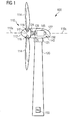
- FIG. 1 shows a wind turbine 100 according to an embodiment of the invention.
- the wind turbine 100 comprises a tower 120, which is mounted on a non-depicted fundament.
- a nacelle 122 On top of the tower 120 there is arranged a nacelle 122.
- a yaw angle adjustment device 121 In between the tower 120 and the nacelle 122 there is provided a yaw angle adjustment device 121, which is capable of rotating the nacelle 122 around a non depicted vertical axis, which is aligned with the longitudinal extension of the tower 120.
- the yaw angle adjustment device 121 can also be used to adjust the yaw angle to a position, wherein the nacelle 122 is intentionally not perfectly aligned with the current wind direction.
- the wind turbine 100 further comprises a rotor 110 having three blades 114. In the perspective of Figure 1 only two blades 114 are visible.
- the rotor 110 is rotatable around a rotational axis 110a.
- the blades 114 which are mounted at a hub 112, extend radially with respect to the rotational axis 110a.
- a blade adjustment device 116 in order to adjust the blade pitch angle of each blade 114 by rotating the respective blade 114 around a non depicted axis being aligned substantially parallel with the longitudinal extension of the blade 114.
- the blade pitch angle of the respective blade 114 can be adjusted in such a manner that at least when the wind is not so strong a maximum wind power can be retrieved from the available wind power.
- the blade pitch angle can also be intentionally adjusted to a position, in which only a reduced wind power can be captured.
- a gear box 124 is used to convert the number of revolutions of the rotor 110 into a higher number of revolutions of a shaft 125, which is coupled in a known manner to an electromechanical transducer 140.
- the electromechanical transducer is a generator 140.
- a brake 126 is provided in order to stop the operation of the wind turbine 100 or to reduce the rotational speed of the rotor 110 for instance (a) in case of an emergency, (b) in case of too strong wind conditions, which might harm the wind turbine 100, and/or (c) in case of an intentional saving of the consumed fatigue life time and/or the fatigue life time consumption rate of at least one structural component of the wind turbine 100.
- the wind turbine 100 further comprises a control system 153 for operating the wind turbine 100 in a highly efficient manner. Apart from controlling for instance the yaw angle adjustment device 121 the depicted control system 153 is also used for adjusting the blade pitch angle of the rotor blades 114 in an optimized manner.
- the generator 140 comprises a stator assembly 145 and a rotor arrangement 150.
- the stator assembly 145 comprises a plurality of coils for generating electrical current in response to a time alternating magnetic flux.
- the rotor arrangement comprises a plurality of permanent magnets, which are arranged in rows being aligned with a longitudinal axis of the rotor arrangement 150.
- the permanent magnets being assigned to one row are engaged with a support structure of the rotor arrangement, wherein a contour of a magnet assembly comprising the permanent magnets is adapted to engage with a complementary contour of the support structure.
- Figure 2a shows in a cross sectional view two magnet assemblies 280, which are engaged in a dove tail arrangement with the support structure 281 of the rotor assembly shown in Figure 1 .
- the magnet assemblies comprise a base element 272 and a permanent magnet 271 being positioned on the base element.
- the base element 272 comprises a recess or groove 273 as contour.
- the support structure 281 of the rotor comprises a protrusion 282 as complementary contour. The distance between two protrusions is shown as length L.
- Figure 2b shows in a cross sectional view two magnet assemblies, which are engaged in a dove tail arrangement, opposite as shown in Figure 2a , with the support structure of the rotor assembly shown in Figure 1 .
- Figure 2b shows two magnet assemblies 280, which are engaged in a dove tail arrangement with the support structure 281 of the rotor assembly shown in Figure 1 .
- the magnet assemblies comprise a base element 272 and a permanent magnet 271 being positioned on the base element.
- the base element 272 comprises protrusion 273 as contour.
- the support structure 281 of the rotor comprises a recess or groove 282 as complementary contour. The length of one recess of the support structure is shown as length L.
- Figure 3 shows in a perspective view the magnet assembly 260 as shown in Figure 2b .
- the support structure 281 of the rotor comprises a recess 282.
- the magnet assembly comprises a base element 272, 273 consisting of a plate part 272 and a protrusion part 273.
- a magnet or permanent magnet 271 is positioned on the plate part.
- the magnet assembly may be inserted into the recess of the support structure from one or two sides of the support structure as shown in Figure 3 in a slidable manner, wherein the recess or groove extend in the longitudinal axial direction of the central shaft of the rotor arrangement.
- This embodiment may also be implemented vice versa, that means the magnet assembly comprising a recess and the support structure comprising a protrusion.
- FIG 4 shows in a perspective view a row of magnet assemblies 400 engaged with the support structure of the rotor assembly shown in Figure 1 .
- the row of magnet assemblies comprises a plurality of magnet assemblies.
- Each magnet assembly 260 comprises a base element comprising a plate part 272 and a protrusion part 273.
- a magnet 271 is positioned on the plate part 272.
- Each magnet assembly 260 is inserted by sliding into a recess or groove 282 of the support structure 281.
- the recess and the protrusion may also be arranged vice versa, that means the magnet assemblies comprising the recess and the support structure comprising the protrusion.
- the protrusion 273 is adapted to engage with the complementary contour of the support structure, i.e. with the recess 282. This provides the advantage that the base element 272, 273 and therefore the magnet assembly 260 and the support structure 281 can be mechanically connected to each other in a reliable manner without using any specific tools such as a screwdriver or a spanner.
- the magnet assembly when manufacturing the rotor arrangement the magnet assembly may be inserted into the groove or put onto a protrusion of a central shaft of the rotor arrangement in a slidable manner, wherein the groove or the protrusion extend in the longitudinal axial direction of the central shaft.
- each magnet By using a contour (for instance a protrusion) and a complementary contour (for instance a recess), each magnet may be pushed safely in place providing a great advantage in contrast to traditional mounting, where each magnet is installed without any guidance and where the magnet can be pulled to another object by magnetic force. Further, the magnet assembly may be more safely handled in production as the magnets that are used may be very strong and constitute a potential safety hazard if not handled correctly, but may be easily mounted as the contour arrangement, for instance a dove tail arrangement, may provide a secure guidance for the positioning of the magnets as shown for example in Figure 4 .
- a contour for instance a protrusion
- a complementary contour for instance a recess
Landscapes
- Engineering & Computer Science (AREA)
- Power Engineering (AREA)
- Life Sciences & Earth Sciences (AREA)
- Sustainable Energy (AREA)
- Sustainable Development (AREA)
- Physics & Mathematics (AREA)
- Electromagnetism (AREA)
- Chemical & Material Sciences (AREA)
- Combustion & Propulsion (AREA)
- Mechanical Engineering (AREA)
- General Engineering & Computer Science (AREA)
- Permanent Field Magnets Of Synchronous Machinery (AREA)
- Wind Motors (AREA)
Priority Applications (12)
| Application Number | Priority Date | Filing Date | Title |
|---|---|---|---|
| ES10000542.0T ES2519166T3 (es) | 2010-01-20 | 2010-01-20 | Conjunto de imán |
| EP10000542.0A EP2348619B1 (de) | 2010-01-20 | 2010-01-20 | Magnetanordnung |
| DK10000542.0T DK2348619T3 (da) | 2010-01-20 | 2010-01-20 | Magnetenhed |
| BR112012017816A BR112012017816A2 (pt) | 2010-01-20 | 2011-01-11 | montagem de ímãs |
| EP11700641.1A EP2494682B1 (de) | 2010-01-20 | 2011-01-11 | Magnetbaugruppe |
| US13/522,776 US20120286520A1 (en) | 2010-01-20 | 2011-01-11 | Magnet assembly |
| PCT/EP2011/050262 WO2011089040A2 (en) | 2010-01-20 | 2011-01-11 | Magnet assembly |
| CN201180006749.1A CN102714450B (zh) | 2010-01-20 | 2011-01-11 | 磁体组件 |
| KR1020127021640A KR101765542B1 (ko) | 2010-01-20 | 2011-01-11 | 자석 어셈블리 |
| CA2728557A CA2728557C (en) | 2010-01-20 | 2011-01-18 | Magnet assembly |
| US13/008,093 US9379583B2 (en) | 2010-01-20 | 2011-01-18 | Magnet assembly |
| CN2011100227914A CN102130517A (zh) | 2010-01-20 | 2011-01-20 | 磁体组件 |
Applications Claiming Priority (1)
| Application Number | Priority Date | Filing Date | Title |
|---|---|---|---|
| EP10000542.0A EP2348619B1 (de) | 2010-01-20 | 2010-01-20 | Magnetanordnung |
Publications (2)
| Publication Number | Publication Date |
|---|---|
| EP2348619A1 true EP2348619A1 (de) | 2011-07-27 |
| EP2348619B1 EP2348619B1 (de) | 2014-09-17 |
Family
ID=42310623
Family Applications (2)
| Application Number | Title | Priority Date | Filing Date |
|---|---|---|---|
| EP10000542.0A Active EP2348619B1 (de) | 2010-01-20 | 2010-01-20 | Magnetanordnung |
| EP11700641.1A Active EP2494682B1 (de) | 2010-01-20 | 2011-01-11 | Magnetbaugruppe |
Family Applications After (1)
| Application Number | Title | Priority Date | Filing Date |
|---|---|---|---|
| EP11700641.1A Active EP2494682B1 (de) | 2010-01-20 | 2011-01-11 | Magnetbaugruppe |
Country Status (9)
| Country | Link |
|---|---|
| US (2) | US20120286520A1 (de) |
| EP (2) | EP2348619B1 (de) |
| KR (1) | KR101765542B1 (de) |
| CN (2) | CN102714450B (de) |
| BR (1) | BR112012017816A2 (de) |
| CA (1) | CA2728557C (de) |
| DK (1) | DK2348619T3 (de) |
| ES (1) | ES2519166T3 (de) |
| WO (1) | WO2011089040A2 (de) |
Cited By (15)
| Publication number | Priority date | Publication date | Assignee | Title |
|---|---|---|---|---|
| WO2012031923A1 (de) * | 2010-09-08 | 2012-03-15 | Siemens Aktiengesellschaft | Rotor für eine elektrische maschine |
| EP2555393A1 (de) * | 2011-08-01 | 2013-02-06 | Siemens Aktiengesellschaft | Magnetladevorrichtung |
| EP2555385A1 (de) * | 2011-08-01 | 2013-02-06 | Siemens Aktiengesellschaft | Dauermagnetanordnung mit Abdeckung aus Formkunststoff und Verfahren zum Schützen eines Dauermagneten |
| EP2555382A1 (de) * | 2011-08-01 | 2013-02-06 | Siemens Aktiengesellschaft | Dauermagnetanordnung und Verfahren zur Befestigung eines Dauermagneten auf einer Grundplatte |
| EP2555386A1 (de) * | 2011-08-01 | 2013-02-06 | Siemens Aktiengesellschaft | Stangensperrvorrichtung |
| EP2555383A1 (de) * | 2011-08-01 | 2013-02-06 | Siemens Aktiengesellschaft | Dauermagnetanordnung mit verschiebbarer Befestigung und Verfahren zur Befestigung eines Dauermagneten auf einer Grundplatte |
| EP2555384A1 (de) * | 2011-08-01 | 2013-02-06 | Siemens Aktiengesellschaft | Feldstruktur einer elektrischen Maschine |
| KR20140143356A (ko) * | 2012-03-26 | 2014-12-16 | 롤스-로이스 마린 에이에스 | 분할된 요우크를 포함하는 회전자 |
| US10042011B2 (en) | 2015-07-27 | 2018-08-07 | Siemens Aktiengesellschaft | Method to detect or monitor the demagnetization of a magnet |
| US10193402B2 (en) | 2014-09-26 | 2019-01-29 | Ge Renewable Technologies Wind B.V. | Fastening system for coupling electrical machine components |
| EP3258572A4 (de) * | 2014-08-21 | 2019-04-03 | Jiangxi Gongbu Machinery Co., Ltd. | Elektromotoraussenrotor mit niedriger drehzahl und hohem drehmoment, elektromotor und zugehöriger kran |
| EP3490109A1 (de) * | 2017-11-23 | 2019-05-29 | Siemens Gamesa Renewable Energy A/S | Permanentmagnetträger eines permanentmagnetgenerators |
| EP3748817A1 (de) * | 2019-06-06 | 2020-12-09 | Siemens Gamesa Renewable Energy A/S | Permanentmagnetmodul für eine permanentmagnetmaschine |
| EP3859943A1 (de) * | 2020-02-03 | 2021-08-04 | Siemens Gamesa Renewable Energy A/S | Magnetsystem für einen rotor und elektrische permanentmagnetmaschine |
| EP4037148A1 (de) * | 2021-01-28 | 2022-08-03 | Siemens Gamesa Renewable Energy A/S | Permanentmagnetmodul für eine permanentmagnetmaschine |
Families Citing this family (14)
| Publication number | Priority date | Publication date | Assignee | Title |
|---|---|---|---|---|
| ES2519166T3 (es) * | 2010-01-20 | 2014-11-06 | Siemens Aktiengesellschaft | Conjunto de imán |
| EP2947752A1 (de) * | 2014-05-19 | 2015-11-25 | ALSTOM Renewable Technologies | Keilmechanismus |
| CN105281530B (zh) * | 2014-07-11 | 2018-11-09 | 上海微电子装备(集团)股份有限公司 | 具有重力补偿功能的圆筒型音圈电机 |
| DK178456B1 (en) * | 2014-08-28 | 2016-03-14 | Envision Energy Denmark Aps | Synchronous superconductive rotary machine having a slidable pole assembly and methods thereof |
| JP6407825B2 (ja) * | 2015-09-02 | 2018-10-17 | 信越化学工業株式会社 | 永久磁石磁気回路の製造方法 |
| DE102016114362A1 (de) * | 2016-08-03 | 2018-02-08 | Feaam Gmbh | Rotor für eine elektrische Maschine sowie elektrische Maschine |
| EP3567701B1 (de) * | 2018-05-09 | 2023-02-01 | Siemens Gamesa Renewable Energy A/S | Magnetmodul für eine dauermagnetmaschine |
| EP3657641B1 (de) | 2018-11-26 | 2023-09-06 | LG Electronics Inc. | Motor |
| CN109995163B (zh) * | 2019-04-22 | 2023-09-01 | 金风科技股份有限公司 | 磁极模块、磁轭、转子和电机 |
| CN111987870B (zh) * | 2019-05-23 | 2023-03-24 | 北京金风科创风电设备有限公司 | 大直径电机的装配方法 |
| CN111048279A (zh) * | 2019-12-18 | 2020-04-21 | 宁波韵升股份有限公司 | 一种磁力吸盘及其制作方法 |
| US20220103036A1 (en) * | 2020-09-29 | 2022-03-31 | Nichia Corporation | Yoke for rotor of axial gap motor |
| EP4109717A1 (de) * | 2021-06-23 | 2022-12-28 | Siemens Gamesa Renewable Energy A/S | Rotor für eine elektrische maschine |
| KR102454798B1 (ko) * | 2021-10-07 | 2022-10-14 | 유니슨 주식회사 | 풍력터빈용 발전기 회전자의 자석 조립 장치 |
Citations (3)
| Publication number | Priority date | Publication date | Assignee | Title |
|---|---|---|---|---|
| JP2006034024A (ja) * | 2004-07-20 | 2006-02-02 | Fuji Electric Systems Co Ltd | 回転電気機械の永久磁石式回転子 |
| WO2007119952A1 (en) * | 2006-04-14 | 2007-10-25 | Unison Co., Ltd. | Rotor for wind turbine and assembling method thereof |
| EP2017859A1 (de) * | 2007-07-20 | 2009-01-21 | Siemens Aktiengesellschaft | Verfahren zur Herstellung von Magnetpolen |
Family Cites Families (16)
| Publication number | Priority date | Publication date | Assignee | Title |
|---|---|---|---|---|
| US4445062A (en) * | 1978-12-26 | 1984-04-24 | The Garrett Corporation | Rotor assembly having anchors with undulating sides |
| JPS5641760A (en) * | 1979-09-13 | 1981-04-18 | Toshiba Corp | Rotary electric machine |
| JPS60102851A (ja) * | 1983-11-09 | 1985-06-07 | Toshiba Corp | 永久磁石回転子とその製造方法 |
| JPS61164807A (ja) * | 1985-01-18 | 1986-07-25 | Mitsubishi Electric Corp | ビデオプロジエクタ−用スクリ−ンの製造方法 |
| GB2217924B (en) * | 1988-04-25 | 1992-10-07 | Matsushita Electric Works Ltd | Permanent magnet rotor |
| US5063318A (en) * | 1989-08-25 | 1991-11-05 | Sundstrand Corporation | Preloaded permanent magnet rotor assembly |
| DE19751710A1 (de) * | 1997-11-21 | 1999-05-27 | Leybold Systems Gmbh | Magnetkörper mit Korrosionsschutzbeschichtung |
| CN1442279A (zh) * | 2003-04-11 | 2003-09-17 | 北京玻璃钢研究设计院 | 复合材料真空注射成型方法 |
| DE102004027036A1 (de) * | 2004-06-02 | 2005-12-22 | Etel S.A. | Synchronmotor |
| JP4517738B2 (ja) | 2004-06-15 | 2010-08-04 | 株式会社ニコン | 補助光学系の回転防止装置 |
| DE102004058451B4 (de) * | 2004-12-03 | 2008-04-10 | Vacuumschmelze Gmbh & Co. Kg | Verfahren zur Herstellung von Magnetsystemen und danach hergestellte Magnetsysteme |
| US7573168B2 (en) * | 2005-10-24 | 2009-08-11 | General Electric Company | Method and apparatus for assembling a permanent magnet pole assembly |
| US8598761B2 (en) * | 2007-05-03 | 2013-12-03 | In Motion Technologies Pty., Ltd. | Rotor magnet positioning device |
| JP2009112158A (ja) * | 2007-10-31 | 2009-05-21 | Aisan Ind Co Ltd | ロータ及びポンプ |
| US8018110B2 (en) | 2009-04-30 | 2011-09-13 | General Electric Company | High speed internal permanent magnet machine and method of manufacturing the same |
| ES2519166T3 (es) * | 2010-01-20 | 2014-11-06 | Siemens Aktiengesellschaft | Conjunto de imán |
-
2010
- 2010-01-20 ES ES10000542.0T patent/ES2519166T3/es active Active
- 2010-01-20 DK DK10000542.0T patent/DK2348619T3/da active
- 2010-01-20 EP EP10000542.0A patent/EP2348619B1/de active Active
-
2011
- 2011-01-11 EP EP11700641.1A patent/EP2494682B1/de active Active
- 2011-01-11 WO PCT/EP2011/050262 patent/WO2011089040A2/en active Application Filing
- 2011-01-11 KR KR1020127021640A patent/KR101765542B1/ko active IP Right Grant
- 2011-01-11 BR BR112012017816A patent/BR112012017816A2/pt not_active IP Right Cessation
- 2011-01-11 US US13/522,776 patent/US20120286520A1/en not_active Abandoned
- 2011-01-11 CN CN201180006749.1A patent/CN102714450B/zh active Active
- 2011-01-18 CA CA2728557A patent/CA2728557C/en active Active
- 2011-01-18 US US13/008,093 patent/US9379583B2/en active Active
- 2011-01-20 CN CN2011100227914A patent/CN102130517A/zh active Pending
Patent Citations (3)
| Publication number | Priority date | Publication date | Assignee | Title |
|---|---|---|---|---|
| JP2006034024A (ja) * | 2004-07-20 | 2006-02-02 | Fuji Electric Systems Co Ltd | 回転電気機械の永久磁石式回転子 |
| WO2007119952A1 (en) * | 2006-04-14 | 2007-10-25 | Unison Co., Ltd. | Rotor for wind turbine and assembling method thereof |
| EP2017859A1 (de) * | 2007-07-20 | 2009-01-21 | Siemens Aktiengesellschaft | Verfahren zur Herstellung von Magnetpolen |
Cited By (22)
| Publication number | Priority date | Publication date | Assignee | Title |
|---|---|---|---|---|
| WO2012031923A1 (de) * | 2010-09-08 | 2012-03-15 | Siemens Aktiengesellschaft | Rotor für eine elektrische maschine |
| US9257890B2 (en) | 2010-09-08 | 2016-02-09 | Siemens Aktiengesellschaft | Permanent magnet rotor for an electrical machine |
| US9048711B2 (en) | 2011-08-01 | 2015-06-02 | Siemens Aktiengesellschaft | Field structure of an electrical machine |
| EP2555393A1 (de) * | 2011-08-01 | 2013-02-06 | Siemens Aktiengesellschaft | Magnetladevorrichtung |
| EP2555386A1 (de) * | 2011-08-01 | 2013-02-06 | Siemens Aktiengesellschaft | Stangensperrvorrichtung |
| EP2555383A1 (de) * | 2011-08-01 | 2013-02-06 | Siemens Aktiengesellschaft | Dauermagnetanordnung mit verschiebbarer Befestigung und Verfahren zur Befestigung eines Dauermagneten auf einer Grundplatte |
| CN102916535A (zh) * | 2011-08-01 | 2013-02-06 | 西门子公司 | 磁体装载装置 |
| EP2555384A1 (de) * | 2011-08-01 | 2013-02-06 | Siemens Aktiengesellschaft | Feldstruktur einer elektrischen Maschine |
| US8800132B2 (en) | 2011-08-01 | 2014-08-12 | Siemens Aktiengesellschaft | Magnet loading apparatus |
| CN102916535B (zh) * | 2011-08-01 | 2016-12-21 | 西门子公司 | 磁体装载装置 |
| EP2555385A1 (de) * | 2011-08-01 | 2013-02-06 | Siemens Aktiengesellschaft | Dauermagnetanordnung mit Abdeckung aus Formkunststoff und Verfahren zum Schützen eines Dauermagneten |
| EP2555382A1 (de) * | 2011-08-01 | 2013-02-06 | Siemens Aktiengesellschaft | Dauermagnetanordnung und Verfahren zur Befestigung eines Dauermagneten auf einer Grundplatte |
| EP2831979A4 (de) * | 2012-03-26 | 2016-07-27 | Rolls Royce Marine As | Rotor mit segmentiertem joch |
| KR20140143356A (ko) * | 2012-03-26 | 2014-12-16 | 롤스-로이스 마린 에이에스 | 분할된 요우크를 포함하는 회전자 |
| EP3258572A4 (de) * | 2014-08-21 | 2019-04-03 | Jiangxi Gongbu Machinery Co., Ltd. | Elektromotoraussenrotor mit niedriger drehzahl und hohem drehmoment, elektromotor und zugehöriger kran |
| US10193402B2 (en) | 2014-09-26 | 2019-01-29 | Ge Renewable Technologies Wind B.V. | Fastening system for coupling electrical machine components |
| EP3001539B1 (de) * | 2014-09-26 | 2019-03-20 | GE Renewable Technologies Wind B.V. | Elektrische Maschinen |
| US10042011B2 (en) | 2015-07-27 | 2018-08-07 | Siemens Aktiengesellschaft | Method to detect or monitor the demagnetization of a magnet |
| EP3490109A1 (de) * | 2017-11-23 | 2019-05-29 | Siemens Gamesa Renewable Energy A/S | Permanentmagnetträger eines permanentmagnetgenerators |
| EP3748817A1 (de) * | 2019-06-06 | 2020-12-09 | Siemens Gamesa Renewable Energy A/S | Permanentmagnetmodul für eine permanentmagnetmaschine |
| EP3859943A1 (de) * | 2020-02-03 | 2021-08-04 | Siemens Gamesa Renewable Energy A/S | Magnetsystem für einen rotor und elektrische permanentmagnetmaschine |
| EP4037148A1 (de) * | 2021-01-28 | 2022-08-03 | Siemens Gamesa Renewable Energy A/S | Permanentmagnetmodul für eine permanentmagnetmaschine |
Also Published As
| Publication number | Publication date |
|---|---|
| EP2494682B1 (de) | 2017-08-16 |
| CN102714450A (zh) | 2012-10-03 |
| WO2011089040A2 (en) | 2011-07-28 |
| BR112012017816A2 (pt) | 2016-04-19 |
| KR20120127603A (ko) | 2012-11-22 |
| DK2348619T3 (da) | 2014-10-13 |
| US9379583B2 (en) | 2016-06-28 |
| EP2348619B1 (de) | 2014-09-17 |
| ES2519166T3 (es) | 2014-11-06 |
| CA2728557A1 (en) | 2011-07-20 |
| CA2728557C (en) | 2018-01-30 |
| US20110175364A1 (en) | 2011-07-21 |
| WO2011089040A3 (en) | 2012-03-15 |
| CN102130517A (zh) | 2011-07-20 |
| US20120286520A1 (en) | 2012-11-15 |
| CN102714450B (zh) | 2015-07-01 |
| KR101765542B1 (ko) | 2017-08-07 |
| EP2494682A2 (de) | 2012-09-05 |
Similar Documents
| Publication | Publication Date | Title |
|---|---|---|
| US9379583B2 (en) | Magnet assembly | |
| US8648511B2 (en) | Magnetic component part for a rotor assembly | |
| US8664819B2 (en) | Method and apparatus for permanent magnet attachment in an electromechanical machine | |
| EP2555385B1 (de) | Dauermagnetanordnung mit Abdeckung aus Formkunststoff und Verfahren zum Schützen eines Dauermagneten | |
| EP2722855A1 (de) | Nd-Fe-B-Dauermagnet ohne Dysprosium, Rotoranordnung, elektromechanischer Wandler, Windturbine | |
| EP2555383B1 (de) | Dauermagnetanordnung mit verschiebarer Befestigung und Verfahren zur Befestigung eines Dauermagneten auf einer Grundplatte | |
| EP2555381A1 (de) | Dauermagnetanordnung mit geflanschter Abdeckung und Verfahren zur Befestigung eines Dauermagneten auf einer Grundplatte | |
| EP2555384A1 (de) | Feldstruktur einer elektrischen Maschine | |
| EP2897265A1 (de) | Rotor mit einer in axialer Richtung ausgerichteten Permanentmagnetanordnung und elektrische Maschine mit einem solchen Rotor | |
| EP2555382A1 (de) | Dauermagnetanordnung und Verfahren zur Befestigung eines Dauermagneten auf einer Grundplatte | |
| CN109361274A (zh) | 一种模块式直驱永磁发电机定子及直驱永磁发电机 | |
| US11942839B2 (en) | Method for removing active stator parts | |
| EP4170871A1 (de) | Elektrische maschinenzahnanordnungen und verfahren | |
| EP3402046B1 (de) | Permanentmagnetmodule | |
| JP2021197903A (ja) | 永久磁石の磁化 |
Legal Events
| Date | Code | Title | Description |
|---|---|---|---|
| PUAI | Public reference made under article 153(3) epc to a published international application that has entered the european phase |
Free format text: ORIGINAL CODE: 0009012 |
|
| AK | Designated contracting states |
Kind code of ref document: A1 Designated state(s): AT BE BG CH CY CZ DE DK EE ES FI FR GB GR HR HU IE IS IT LI LT LU LV MC MK MT NL NO PL PT RO SE SI SK SM TR |
|
| AX | Request for extension of the european patent |
Extension state: AL BA RS |
|
| 17P | Request for examination filed |
Effective date: 20110819 |
|
| RAP1 | Party data changed (applicant data changed or rights of an application transferred) |
Owner name: SIEMENS AKTIENGESELLSCHAFT |
|
| 17Q | First examination report despatched |
Effective date: 20130325 |
|
| GRAP | Despatch of communication of intention to grant a patent |
Free format text: ORIGINAL CODE: EPIDOSNIGR1 |
|
| INTG | Intention to grant announced |
Effective date: 20140410 |
|
| GRAS | Grant fee paid |
Free format text: ORIGINAL CODE: EPIDOSNIGR3 |
|
| GRAA | (expected) grant |
Free format text: ORIGINAL CODE: 0009210 |
|
| AK | Designated contracting states |
Kind code of ref document: B1 Designated state(s): AT BE BG CH CY CZ DE DK EE ES FI FR GB GR HR HU IE IS IT LI LT LU LV MC MK MT NL NO PL PT RO SE SI SK SM TR |
|
| REG | Reference to a national code |
Ref country code: GB Ref legal event code: FG4D |
|
| REG | Reference to a national code |
Ref country code: CH Ref legal event code: EP |
|
| REG | Reference to a national code |
Ref country code: IE Ref legal event code: FG4D |
|
| REG | Reference to a national code |
Ref country code: DK Ref legal event code: T3 Effective date: 20141006 |
|
| REG | Reference to a national code |
Ref country code: AT Ref legal event code: REF Ref document number: 688077 Country of ref document: AT Kind code of ref document: T Effective date: 20141015 |
|
| REG | Reference to a national code |
Ref country code: DE Ref legal event code: R096 Ref document number: 602010018959 Country of ref document: DE Effective date: 20141030 |
|
| REG | Reference to a national code |
Ref country code: ES Ref legal event code: FG2A Ref document number: 2519166 Country of ref document: ES Kind code of ref document: T3 Effective date: 20141106 |
|
| PG25 | Lapsed in a contracting state [announced via postgrant information from national office to epo] |
Ref country code: GR Free format text: LAPSE BECAUSE OF FAILURE TO SUBMIT A TRANSLATION OF THE DESCRIPTION OR TO PAY THE FEE WITHIN THE PRESCRIBED TIME-LIMIT Effective date: 20141218 Ref country code: LT Free format text: LAPSE BECAUSE OF FAILURE TO SUBMIT A TRANSLATION OF THE DESCRIPTION OR TO PAY THE FEE WITHIN THE PRESCRIBED TIME-LIMIT Effective date: 20140917 Ref country code: FI Free format text: LAPSE BECAUSE OF FAILURE TO SUBMIT A TRANSLATION OF THE DESCRIPTION OR TO PAY THE FEE WITHIN THE PRESCRIBED TIME-LIMIT Effective date: 20140917 Ref country code: SE Free format text: LAPSE BECAUSE OF FAILURE TO SUBMIT A TRANSLATION OF THE DESCRIPTION OR TO PAY THE FEE WITHIN THE PRESCRIBED TIME-LIMIT Effective date: 20140917 Ref country code: NO Free format text: LAPSE BECAUSE OF FAILURE TO SUBMIT A TRANSLATION OF THE DESCRIPTION OR TO PAY THE FEE WITHIN THE PRESCRIBED TIME-LIMIT Effective date: 20141217 |
|
| REG | Reference to a national code |
Ref country code: NL Ref legal event code: VDEP Effective date: 20140917 |
|
| REG | Reference to a national code |
Ref country code: LT Ref legal event code: MG4D |
|
| PG25 | Lapsed in a contracting state [announced via postgrant information from national office to epo] |
Ref country code: HR Free format text: LAPSE BECAUSE OF FAILURE TO SUBMIT A TRANSLATION OF THE DESCRIPTION OR TO PAY THE FEE WITHIN THE PRESCRIBED TIME-LIMIT Effective date: 20140917 Ref country code: LV Free format text: LAPSE BECAUSE OF FAILURE TO SUBMIT A TRANSLATION OF THE DESCRIPTION OR TO PAY THE FEE WITHIN THE PRESCRIBED TIME-LIMIT Effective date: 20140917 Ref country code: CY Free format text: LAPSE BECAUSE OF FAILURE TO SUBMIT A TRANSLATION OF THE DESCRIPTION OR TO PAY THE FEE WITHIN THE PRESCRIBED TIME-LIMIT Effective date: 20140917 |
|
| REG | Reference to a national code |
Ref country code: AT Ref legal event code: MK05 Ref document number: 688077 Country of ref document: AT Kind code of ref document: T Effective date: 20140917 |
|
| PG25 | Lapsed in a contracting state [announced via postgrant information from national office to epo] |
Ref country code: NL Free format text: LAPSE BECAUSE OF FAILURE TO SUBMIT A TRANSLATION OF THE DESCRIPTION OR TO PAY THE FEE WITHIN THE PRESCRIBED TIME-LIMIT Effective date: 20140917 |
|
| PG25 | Lapsed in a contracting state [announced via postgrant information from national office to epo] |
Ref country code: IS Free format text: LAPSE BECAUSE OF FAILURE TO SUBMIT A TRANSLATION OF THE DESCRIPTION OR TO PAY THE FEE WITHIN THE PRESCRIBED TIME-LIMIT Effective date: 20150117 Ref country code: SK Free format text: LAPSE BECAUSE OF FAILURE TO SUBMIT A TRANSLATION OF THE DESCRIPTION OR TO PAY THE FEE WITHIN THE PRESCRIBED TIME-LIMIT Effective date: 20140917 Ref country code: EE Free format text: LAPSE BECAUSE OF FAILURE TO SUBMIT A TRANSLATION OF THE DESCRIPTION OR TO PAY THE FEE WITHIN THE PRESCRIBED TIME-LIMIT Effective date: 20140917 Ref country code: PT Free format text: LAPSE BECAUSE OF FAILURE TO SUBMIT A TRANSLATION OF THE DESCRIPTION OR TO PAY THE FEE WITHIN THE PRESCRIBED TIME-LIMIT Effective date: 20150119 Ref country code: RO Free format text: LAPSE BECAUSE OF FAILURE TO SUBMIT A TRANSLATION OF THE DESCRIPTION OR TO PAY THE FEE WITHIN THE PRESCRIBED TIME-LIMIT Effective date: 20140917 Ref country code: CZ Free format text: LAPSE BECAUSE OF FAILURE TO SUBMIT A TRANSLATION OF THE DESCRIPTION OR TO PAY THE FEE WITHIN THE PRESCRIBED TIME-LIMIT Effective date: 20140917 |
|
| PG25 | Lapsed in a contracting state [announced via postgrant information from national office to epo] |
Ref country code: AT Free format text: LAPSE BECAUSE OF FAILURE TO SUBMIT A TRANSLATION OF THE DESCRIPTION OR TO PAY THE FEE WITHIN THE PRESCRIBED TIME-LIMIT Effective date: 20140917 Ref country code: PL Free format text: LAPSE BECAUSE OF FAILURE TO SUBMIT A TRANSLATION OF THE DESCRIPTION OR TO PAY THE FEE WITHIN THE PRESCRIBED TIME-LIMIT Effective date: 20140917 |
|
| REG | Reference to a national code |
Ref country code: DE Ref legal event code: R097 Ref document number: 602010018959 Country of ref document: DE |
|
| PG25 | Lapsed in a contracting state [announced via postgrant information from national office to epo] |
Ref country code: BE Free format text: LAPSE BECAUSE OF NON-PAYMENT OF DUE FEES Effective date: 20150131 |
|
| PLBE | No opposition filed within time limit |
Free format text: ORIGINAL CODE: 0009261 |
|
| STAA | Information on the status of an ep patent application or granted ep patent |
Free format text: STATUS: NO OPPOSITION FILED WITHIN TIME LIMIT |
|
| 26N | No opposition filed |
Effective date: 20150618 |
|
| REG | Reference to a national code |
Ref country code: CH Ref legal event code: PL |
|
| PG25 | Lapsed in a contracting state [announced via postgrant information from national office to epo] |
Ref country code: IT Free format text: LAPSE BECAUSE OF FAILURE TO SUBMIT A TRANSLATION OF THE DESCRIPTION OR TO PAY THE FEE WITHIN THE PRESCRIBED TIME-LIMIT Effective date: 20140917 Ref country code: LU Free format text: LAPSE BECAUSE OF FAILURE TO SUBMIT A TRANSLATION OF THE DESCRIPTION OR TO PAY THE FEE WITHIN THE PRESCRIBED TIME-LIMIT Effective date: 20150120 |
|
| PG25 | Lapsed in a contracting state [announced via postgrant information from national office to epo] |
Ref country code: MC Free format text: LAPSE BECAUSE OF FAILURE TO SUBMIT A TRANSLATION OF THE DESCRIPTION OR TO PAY THE FEE WITHIN THE PRESCRIBED TIME-LIMIT Effective date: 20140917 |
|
| PG25 | Lapsed in a contracting state [announced via postgrant information from national office to epo] |
Ref country code: CH Free format text: LAPSE BECAUSE OF NON-PAYMENT OF DUE FEES Effective date: 20150131 Ref country code: LI Free format text: LAPSE BECAUSE OF NON-PAYMENT OF DUE FEES Effective date: 20150131 |
|
| REG | Reference to a national code |
Ref country code: IE Ref legal event code: MM4A |
|
| PG25 | Lapsed in a contracting state [announced via postgrant information from national office to epo] |
Ref country code: SI Free format text: LAPSE BECAUSE OF FAILURE TO SUBMIT A TRANSLATION OF THE DESCRIPTION OR TO PAY THE FEE WITHIN THE PRESCRIBED TIME-LIMIT Effective date: 20140917 |
|
| REG | Reference to a national code |
Ref country code: FR Ref legal event code: PLFP Year of fee payment: 7 |
|
| PG25 | Lapsed in a contracting state [announced via postgrant information from national office to epo] |
Ref country code: IE Free format text: LAPSE BECAUSE OF NON-PAYMENT OF DUE FEES Effective date: 20150120 |
|
| PG25 | Lapsed in a contracting state [announced via postgrant information from national office to epo] |
Ref country code: MT Free format text: LAPSE BECAUSE OF FAILURE TO SUBMIT A TRANSLATION OF THE DESCRIPTION OR TO PAY THE FEE WITHIN THE PRESCRIBED TIME-LIMIT Effective date: 20140917 |
|
| REG | Reference to a national code |
Ref country code: FR Ref legal event code: PLFP Year of fee payment: 8 |
|
| PG25 | Lapsed in a contracting state [announced via postgrant information from national office to epo] |
Ref country code: HU Free format text: LAPSE BECAUSE OF FAILURE TO SUBMIT A TRANSLATION OF THE DESCRIPTION OR TO PAY THE FEE WITHIN THE PRESCRIBED TIME-LIMIT; INVALID AB INITIO Effective date: 20100120 Ref country code: BG Free format text: LAPSE BECAUSE OF FAILURE TO SUBMIT A TRANSLATION OF THE DESCRIPTION OR TO PAY THE FEE WITHIN THE PRESCRIBED TIME-LIMIT Effective date: 20140917 Ref country code: SM Free format text: LAPSE BECAUSE OF FAILURE TO SUBMIT A TRANSLATION OF THE DESCRIPTION OR TO PAY THE FEE WITHIN THE PRESCRIBED TIME-LIMIT Effective date: 20140917 |
|
| REG | Reference to a national code |
Ref country code: FR Ref legal event code: PLFP Year of fee payment: 9 |
|
| PG25 | Lapsed in a contracting state [announced via postgrant information from national office to epo] |
Ref country code: MK Free format text: LAPSE BECAUSE OF FAILURE TO SUBMIT A TRANSLATION OF THE DESCRIPTION OR TO PAY THE FEE WITHIN THE PRESCRIBED TIME-LIMIT Effective date: 20140917 |
|
| REG | Reference to a national code |
Ref country code: DE Ref legal event code: R081 Ref document number: 602010018959 Country of ref document: DE Owner name: SIEMENS GAMESA RENEWABLE ENERGY A/S, DK Free format text: FORMER OWNER: SIEMENS AKTIENGESELLSCHAFT, 80333 MUENCHEN, DE |
|
| REG | Reference to a national code |
Ref country code: GB Ref legal event code: 732E Free format text: REGISTERED BETWEEN 20191128 AND 20191204 |
|
| REG | Reference to a national code |
Ref country code: ES Ref legal event code: PC2A Owner name: SIEMENS GAMESA RENEWABLE ENERGY A/S Effective date: 20210311 |
|
| REG | Reference to a national code |
Ref country code: FR Ref legal event code: PLFP Year of fee payment: 14 |
|
| PGFP | Annual fee paid to national office [announced via postgrant information from national office to epo] |
Ref country code: FR Payment date: 20230123 Year of fee payment: 14 Ref country code: DK Payment date: 20230123 Year of fee payment: 14 |
|
| PGFP | Annual fee paid to national office [announced via postgrant information from national office to epo] |
Ref country code: TR Payment date: 20230118 Year of fee payment: 14 |
|
| PGFP | Annual fee paid to national office [announced via postgrant information from national office to epo] |
Ref country code: ES Payment date: 20240216 Year of fee payment: 15 |
|
| PGFP | Annual fee paid to national office [announced via postgrant information from national office to epo] |
Ref country code: DE Payment date: 20240119 Year of fee payment: 15 Ref country code: GB Payment date: 20240124 Year of fee payment: 15 |