EP3859544B1 - Servervorrichtung, datenverteilungssystem, datenbereitstellungsverfahren und programm - Google Patents
Servervorrichtung, datenverteilungssystem, datenbereitstellungsverfahren und programm Download PDFInfo
- Publication number
- EP3859544B1 EP3859544B1 EP18935399.8A EP18935399A EP3859544B1 EP 3859544 B1 EP3859544 B1 EP 3859544B1 EP 18935399 A EP18935399 A EP 18935399A EP 3859544 B1 EP3859544 B1 EP 3859544B1
- Authority
- EP
- European Patent Office
- Prior art keywords
- data
- distribution
- room temperature
- server
- distribution data
- Prior art date
- Legal status (The legal status is an assumption and is not a legal conclusion. Google has not performed a legal analysis and makes no representation as to the accuracy of the status listed.)
- Active
Links
Images


Classifications
-
- G—PHYSICS
- G06—COMPUTING OR CALCULATING; COUNTING
- G06F—ELECTRIC DIGITAL DATA PROCESSING
- G06F16/00—Information retrieval; Database structures therefor; File system structures therefor
- G06F16/20—Information retrieval; Database structures therefor; File system structures therefor of structured data, e.g. relational data
- G06F16/23—Updating
- G06F16/2365—Ensuring data consistency and integrity
-
- G—PHYSICS
- G06—COMPUTING OR CALCULATING; COUNTING
- G06F—ELECTRIC DIGITAL DATA PROCESSING
- G06F16/00—Information retrieval; Database structures therefor; File system structures therefor
- G06F16/80—Information retrieval; Database structures therefor; File system structures therefor of semi-structured data, e.g. markup language structured data such as SGML, XML or HTML
-
- G—PHYSICS
- G06—COMPUTING OR CALCULATING; COUNTING
- G06F—ELECTRIC DIGITAL DATA PROCESSING
- G06F16/00—Information retrieval; Database structures therefor; File system structures therefor
- G06F16/20—Information retrieval; Database structures therefor; File system structures therefor of structured data, e.g. relational data
- G06F16/22—Indexing; Data structures therefor; Storage structures
-
- G—PHYSICS
- G06—COMPUTING OR CALCULATING; COUNTING
- G06F—ELECTRIC DIGITAL DATA PROCESSING
- G06F16/00—Information retrieval; Database structures therefor; File system structures therefor
- G06F16/20—Information retrieval; Database structures therefor; File system structures therefor of structured data, e.g. relational data
- G06F16/23—Updating
- G06F16/2358—Change logging, detection, and notification
-
- G—PHYSICS
- G06—COMPUTING OR CALCULATING; COUNTING
- G06F—ELECTRIC DIGITAL DATA PROCESSING
- G06F16/00—Information retrieval; Database structures therefor; File system structures therefor
- G06F16/20—Information retrieval; Database structures therefor; File system structures therefor of structured data, e.g. relational data
- G06F16/27—Replication, distribution or synchronisation of data between databases or within a distributed database system; Distributed database system architectures therefor
-
- H—ELECTRICITY
- H04—ELECTRIC COMMUNICATION TECHNIQUE
- H04L—TRANSMISSION OF DIGITAL INFORMATION, e.g. TELEGRAPHIC COMMUNICATION
- H04L67/00—Network arrangements or protocols for supporting network services or applications
- H04L67/01—Protocols
- H04L67/12—Protocols specially adapted for proprietary or special-purpose networking environments, e.g. medical networks, sensor networks, networks in vehicles or remote metering networks
Definitions
- the present disclosure relates to a server device, a data distribution system, a data provision method, and a program.
- Patent Literature 1 discloses a sensor network system utilizing ancillary information (format, specification, attribute, and the like) of a sensor terminal.
- ancillary information of the sensor terminal and sensing data from the sensor terminal are managed, in a database, in association with identification information of the sensor terminal.
- Document US 2017/147927 A1 discloses a computer-implemented method, comprising: detecting an abnormal event based on analysis of sensor data, wherein said analysis of the sensor data comprises comparing the sensor data to a user-defined threshold; generating a query based on the detected abnormal event; processing the query against one or more data repositories; executing an inverse model using an output generated in relation to said processing to identify a source of the detected abnormal event, wherein the source comprises an arbitrary shape; and outputting the identified source of the detected abnormal event; wherein the steps are carried out by at least one computing device.
- Patent Literature 1 International Publication No. WO 2016/157271
- Patent Literature 1 in order to search for desired sensing data from the database, ancillary information is merely used as a search condition, and only the sensing data is provided to the user terminal after a search. That is, in Patent Literature 1, only the sensing data is actually distributed, and not merely is the user unable to verify the validity, reliability and the like of the distributed sensing data, but proper use of distributed sensing data cannot be made under existing circumstances, such as use of high-precision sensing data for determination, use of low-precision sensing data for display, and the like.
- an object of the present disclosure is to provide a server device, a data distribution system, a data provision method, and a program for enabling distribution of data that is more appropriate.
- the collection means collects, for example, device data obtained from a device installed in a home, a work place or the like
- the provision means provides, to the outside, (for example, to a server of a data user) distribution data including the device data collected by the collection means and ancillary information about the device data, thereby enabling the external user to verify the validity, reliability and the like of the distribution data based on the ancillary information and to properly use the distribution data based on the ancillary information.
- data can be distributed that is more appropriate.
- Embodiments of the present disclosure are described below in detail with reference to drawings. Components that are the same or equivalent are assigned the same reference signs throughout the drawings.
- a case is described below in which distribution data including device data is collected from a device installed in each house and is provided (distributed) to the outside.
- this case is merely one example, and the present disclosure can be also applied to a case in which distribution data including device data is collected from a device installed in each workplace (offices, factories and the like) or each facility (commercial facilities, schools, hospitals and the like) and provided to the outside.
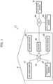
- FIG. 1 is a diagram illustrating one example of overall configuration of a data distribution system 1 according to Embodiment 1 of the present disclosure.
- this data distribution system 1 is a system constructed to deal with (distribute) distribution data including device data and ancillary information.
- the data distribution system 1 includes (i) an air conditioner 10, an lighting device 20, a temperature sensor 30, and a motion sensor 40, which are examples of devices arranged in a house H, (ii) a router 50 for connecting these devices to the Internet N2, (iii) a data collection server 60 for collecting device data (more specifically, distribution data) obtained from these devices, and (iv) a data usage server 70 that uses the distribution data collected by the data collection server 60.
- the data collection server 60 is one example of a server device. Also, FIG. 1 illustrates a case in which the data collection server 60 and the data usage server 70 are connected via the Internet N2. However, this case is merely an example, and alternatively, the data collection server 60 and the data usage server 70 may be connected via a dedicated network.
- the air conditioner 10, the lighting device 20, the temperature sensor 30, and the motion sensor 40 that are arranged in the house H are communicably connected to the router 50 via a wired or wireless home network N1.
- These devices arranged in the house H are merely examples, and such devices may include a water heater, an induction heating (IH) cooker, a rice cooker, a refrigerator, a dehumidifier, and a ventilation fan.
- the router 50 may be omitted if the devices such as the air conditioner 10, the lighting device 20, the temperature sensor 30, and the motion sensor 40 can be directly connected to the Internet N2.
- FIG. 1 a huge number of houses are actually included that have a similar configuration to that of the houses H, and each house is connected to the Internet N2.
- the air conditioner 10 is, for example, a device that performs an air conditioning operation such as cooling, heating, and dehumidification, thereby conditioning air in the room (in the house H).
- the air conditioner 10 includes, for example, a temperature measurement unit disposed near an intake port for taking in indoor air and thus can measure indoor temperature.
- the lighting device 20 is, for example, a device that illuminates a room by making a light emitting diode (LED) or a fluorescent lamp emit light.
- LED light emitting diode
- the temperature sensor 30 is, for example, a device provided with a high-precision semiconductor temperature sensor and measures a temperature in a room.
- the temperature sensor 30 is configured to be capable of measuring a temperature with higher precision than the above-described air conditioner 10 measures a temperature.
- the motion sensor 40 is, for example, a device that detects whether there is a person in a room and detects an amount of movement (a degree of movement) of the person when the person is in the room.
- the motion sensor 40 detects the presence or absence of a person in a room by capturing infrared rays emitted by the person or capturing reflection of an ultrasonic wave.
- the motion sensor 40 detects the amount of movement of the person in the room in accordance with a change in temperature (heat) distribution due to infrared rays or a change in reflection time of the ultrasonic wave.
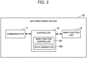
- FIG. 2 is a block diagram for describing configuration of the air conditioner 10.
- the air conditioner 10 includes a communicator 11 that is one example of transmission means, a controller 12, and a main function unit 13.
- the communicator 11 communicates with the router 50 via the home network N1, for example, by wireless communication such as Bluetooth (registered trademark) Low Energy (BLE) or Wi-Fi, or by wired communication such as power line communication (PLC) or Ethernet (registered trademark). More specifically, the communicator 11 communicates with the data collection server 60 through the router 50 and via the Internet N2.
- wireless communication such as Bluetooth (registered trademark) Low Energy (BLE) or Wi-Fi
- PLC power line communication
- Ethernet registered trademark
- the controller 12 includes, for example, a central processing unit (CPU), a read only memory (ROM), a random access memory (RAM) and the like and controls operation of the air conditioner 10 (device). More specifically, the controller 12 functionally includes a main function controller 121 and a data generator 122. These functions are achieved, for example, by the CPU using the RAM as a working memory and appropriately executing a program stored in the ROM.
- CPU central processing unit
- ROM read only memory
- RAM random access memory
- the main function controller 121 controls the main function unit 13 in accordance with, for example, an instruction from the user (for example, an operation of a remote control) to perform an air conditioning operation such as cooling, heating, and dehumidification.
- the data generator 122 generates distribution data serving as a target for distribution for the data distribution system 1.
- the data generator 122 generates distribution data in which ancillary information is added to the device data of the air conditioner 10 (device).
- these data are specifically described.
- the device data is data indicating a state of the air conditioner 10 (device).
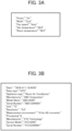
- the device data includes a state of a power supply, a state of an operation mode, a setting state typified by a setting temperature, a detection state typified by a room temperature and the like.
- the content (items) of the device data varies, as appropriate, in accordance with devices.
- the ancillary information is detailed information that should be ancillary to the air conditioner 10 (device) and the device data.
- the ancillary information is stored in the ROM in advance, and as an example illustrated in FIG. 3B , the ancillary information includes (i) information such as a manufacturer, a model, and a model number of the air conditioner 10 (device) and (ii) information of an acquisition time (date and time), unit, precision, resolution and the like of the device data.
- the ancillary information may include the content of processing for the device data.
- the data generator 122 adds ancillary information of FIG. 3B to the device data of FIG. 3A to generate distribution data as illustrated in FIG. 3C .
- the distribution data illustrated in FIG. 3C illustrates a case in which the distribution data is described in a JavaScript (registered trademark) object notation (JSON) format, such a format is merely an example, and the distribution data may be described in another format such as an extensible markup language (XML) format or a comma-separated values (CSV) format.
- JSON JavaScript
- XML extensible markup language
- CSV comma-separated values
- the data generator 122 if a predetermined transmission condition is satisfied (for example, when five minutes elapse since previous transmission if the transmission condition is an interval of five minutes), the data generator 122 generates distribution data as illustrated in FIG. 3C . Also, the data generator 122 transmits the generated distribution data from the communicator 11 to the data collection server 60 (through the router 50).
- the transmission condition may include a time at which a state of the air conditioner 10 (device) is changed. For example, even when the power supply or the operation mode of the air conditioner 10 is changed by a user's instruction, the data generator 122 similarly generates distribution data and transmits the generated distribution data from the communicator 11 to the data collection server 60.
- the main function unit 13 is a component for achieving an air conditioning function such as cooling, heating, and dehumidification, and is, for example, a pump for circulating a refrigerant, a compressor for compressing the refrigerant, an expander for expanding the refrigerant, a fan motor for blowing air, or the like. If the main function unit 13 is another device, the main function unit 13 has a configuration for achieving a function corresponding to the other device. That is, in the case of the lighting device 20, the main function unit 13 is, for example, a light emitting diode (LED), a fluorescent lamp, a peripheral circuit thereof, or the like.
- LED light emitting diode
- the main function unit 13 is, for example, a high-precision semiconductor temperature sensor, a peripheral circuit thereof, or the like.
- the main function unit 13 is, for example, a pyroelectric infrared sensor, a peripheral circuit thereof, or the like.
- the temperature sensor 30 also have configurations similar to such a configuration as illustrated in FIG. 2 , and the motion sensor 40. That is, although the main function unit 13 varies depending on the devices, the data generator 122 generates distribution data in a manner similar to the manner described above. For example, in the case in which the main function unit 13 is the temperature sensor 30, the data generator 122 generates distribution data as illustrated in FIG. 4A . Also, in the case in which the main function unit 13 is the motion sensor 40, the data generator 122 generates distribution data as illustrated in FIG. 4B . The distribution data is also transmitted from the above-described devices (the temperature sensor 30, the motion sensor 40, and the like) to the data collection server 60.
- the router 50 is a communication device that relays communication between the home network N1 and the Internet N2.
- the router 50 may be omitted if the above-described devices such as the air conditioner 10, the lighting device 20, the temperature sensor 30, and the motion sensor 40 can be directly connected to the Internet N2.
- the data collection server 60 is, for example, a server constructed by a device maker (for example, an on-premises server), a public cloud constructed by a cloud vendor, or the like.
- the distribution data collected from a device (the air conditioner 10, the lighting device 20, the temperature sensor 30, the motion sensor 40, or the like) of each home (each house H) is provided (distributed) to the outside.
- FIG. 5 is a block diagram for explaining the configuration of the data collection server 60.
- the data collection server 60 includes a communicator 61, a controller 62, and a data storage 63 that is an example of accumulation means.
- the communicator 61 is, for example, a network interface capable of communicating with the above-described devices (the air conditioner 10, the lighting device 20, the temperature sensor 30, the motion sensor 40, and the like) and the data usage server 70 via the Internet N2.
- the communicator 61 performs communication with the data usage server 70 based on a standardized Web application programming interface (Web API). That is, the distribution data provided from the data collection server 60 to the data usage server 70 is delivered in a data format (for example, JSON format) corresponding to the Web API.
- Web API Web application programming interface
- the controller 62 is equipped with, for example, a CPU, a ROM, a RAM and the like, and controls operation of the data collection server 60. More specifically, the controller 62 functionally includes (i) a data collector 621 that is one example of data collection means, and (ii) a data provider 622 that is one example of provision means. These functions are achieved, for example, by the CPU using the RAM as a working memory and appropriately executing a program stored in the ROM.
- the data collector 621 collects distribution data from devices such as the air conditioner 10, the lighting device 20, the temperature sensor 30, and the motion sensor 40. That is, the data collector 621 controls the communicator 61 to receive the distribution data sent from the devices and store the received distribution data in the data storage 63.
- the data provider 622 provides corresponding distribution data to the data usage server 70 in response to a request from the data usage server 70. For example, when specific content (item) of the ancillary information is specified, the data provider 622 extracts (reads) distribution data including the corresponding ancillary information from the distribution data stored in the data storage 63. Also, the data provider 622 controls the communicator 61 to transmit the extracted distribution data to the data usage server 70.
- the data storage 63 accumulates the distribution data collected by the data collector 621. That is, as illustrated in FIG. 6 , the data storage 63 stores a huge number of distribution data items (distribution data group) collected from each house.
- the data usage server 70 is, for example, a server constructed by a servicer using distribution data (for example, an on-premises server) or a public cloud constructed by a cloud vendor and provides various services using the distribution data provided from the data collection server 60.
- distribution data for example, an on-premises server
- public cloud constructed by a cloud vendor
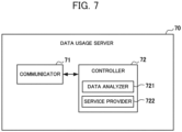
- FIG. 7 is a block diagram for explaining the configuration of the data usage server 70.
- the data usage server 70 is equipped with a communicator 71 and a controller 72.
- the data usage server 70 may further be equipped with a data storage that stores the distribution data provided from the data collection server 60.
- the communicator 71 is, for example, a network interface capable of communicating with the data collection server 60 via the Internet N2.
- the communicator 71 performs communication with the data collection server 60 based on the standardized Web API. That is, the data usage server 70 receives the distribution data transmitted from the data collection server 60 in a data format corresponding to the Web API (for example, JSON format).
- the controller 72 includes, for example, a CPU, a ROM, and a RAM and controls operation of the data usage server 70. More specifically, the controller 72 functionally includes a data analyzer 721 and a service provider 722 that is an example of service provision means. These functions are achieved, for example, by the CPU using the RAM as a working memory and appropriately executing a program stored in the ROM.
- the data analyzer 721 analyzes the distribution data provided from the data collection server 60. For example, in a case in which the data usage server 70 provides a watching-over service (for example, a service for checking safety of a parent whose household is far away), the data analyzer 721 analyzes distribution data of a home (house H) to be watched over and then determines whether there is any abnormality in the home. More specifically, as one example, a case is described in which devices such as the air conditioner 10 and the motion sensor 40 are placed in the home to be watched over and distribution data about those devices is provided from the data collection server 60. In this case, when (i) the power of the air conditioner 10 is in the turned-on state in the above-described distribution data of the air conditioner 10 illustrated in FIG.
- a watching-over service for example, a service for checking safety of a parent whose household is far away
- the data analyzer 721 analyzes distribution data of a home (house H) to be watched over and then determines whether there is any abnormality in the home. More specifically,
- the data analyzer 721 determines that there is abnormality.
- the data analyzer 721 may extend the above-described certain time from 30 minutes to 45 minutes to make determination of the existence of the abnormality. That is, the data analyzer 721 appropriately changes the method of detecting the abnormality in accordance with the ancillary information included in the distribution data.
- the service provider 722 provides necessary information for the user in accordance with a result of the analysis (determination) of the data analyzer 721. For example, in a case in which the data usage server 70 provides the watching-over service, the service provider 722 transmits an email to an address of the registered user (for example, a relative of a person to be watched over) when the data analyzer 721 determines that there is abnormality, thereby giving notice of occurrence of the abnormality.
- the use of an email is merely one example, and, alternatively, the service provider 722 may transmit a message to a social networking service (SNS) account of the registered user to give notice of occurrence of abnormality.
- SNS social networking service
- FIG. 8 is a flowchart illustrating (i) one example of data transmission processing performed by a device such as the air conditioner 10, the lighting device 20, the temperature sensor 30, or the motion sensor 40, and (ii) one example of data accumulation processing performed by the data collection server 60.
- FIG. 9 is a flowchart illustrating one example of watch-over processing performed by the data usage server 70 and one example of data provision processing performed by the data collection server 60.
- the device determines whether the data transmission condition is satisfied (step S101). For example, if the transmission condition is an interval of five minutes, the data generator 122 of the air conditioner 10 determines whether five minutes are elapsed since the previous transmission.
- the transmission condition may include a time at which the state of the air conditioner 10 is changed. In this case, the data generator 122 also determines whether the power supply or the operation mode of the air conditioner 10 is changed.
- step S101 the device determines that the data transmission condition is not satisfied (No in step S101).
- the devices generate device data (step S102).
- the data generator 122 of the air conditioner 10 generates device data as illustrated in FIG. 3A in accordance with the state of the air conditioner 10.
- the device adds ancillary information to the device data to generate distribution data (step S103).
- the data generator 122 of the air conditioner 10 adds ancillary information of FIG. 3B to the device data of FIG. 3A to generate distribution data as illustrated in FIG. 3C .
- the distribution data illustrated in FIG. 3C is described in JSON format, such a format data is merely one example, and the distribution data may be described in another format such as XML format or CSV format.
- the device transmits the generated distribution data to the data collection server 60 (Step S104).
- the communicator 11 of the air conditioner 10 transmits, to the data collection server 60 through the router 50, the distribution data as illustrated in FIG. 3C that is generated in step S103.
- the device is the temperature sensor 30, the distribution data as illustrated in FIG. 4A is transmitted to the data collection server 60.
- the device is the motion sensor 40, the distribution data as illustrated in FIG. 4B is transmitted to the data collection server 60.
- the data collection server 60 determines whether the distribution data is received (step S201). That is, the data collector 621 determines whether the communicator 61 receives the distribution data transmitted from the device.
- the data collection server 60 determines that distribution data is not received (No in step S201), the data collection server 60 stands by until distribution data is received.
- the data collection server 60 accumulates the received distribution data (step S202). That is, the data collector 621 stores the received distribution data in the data storage 63.
- the data usage server 70 designates the contents of the ancillary information to request distribution data (step S301). For example, the data usage server 70 requests the distribution data from the data collection server 60 while specifying specific information (for example, a serial number) of the air conditioner 10 and the motion sensor 40 that are placed in the home (house H) to be watched over.
- specific information for example, a serial number
- the data collection server 60 determines whether there is a request (step S401). That is, the data provider 622 determines whether the communicator 61 receives the request transmitted from the data usage server 70 (the request in which the content of the ancillary information is specified).
- the data collection server 60 determines that there is no request (No in step S401), the data collection server 60 stands by until there is a request.
- the data collection server 60 extracts distribution data corresponding to the request (step S402). That is, the data provider 622 reads, from the data storage 63, distribution data including ancillary information that matches the information (for example, a serial number) unique to the designated device.
- the data collection server 60 provides the distribution data to the data usage server 70 (Step S403). That is, the data provider 622 controls the communicator 61 to transmit the extracted distribution data to the data usage server 70.
- the data usage server 70 receives the distribution data provided from the data collection server 60 (Step S302).
- the data usage server 70 analyzes the received distribution data (step S303). That is, the data analyzer 721 analyzes the distribution data to determine whether there is abnormality. For example, in a case in which (i) in the distribution data of the air conditioner 10 illustrated in FIG. 3C , the air conditioner 10 is in the power-on state and (ii) in the distribution data of the motion sensor 40 illustrated in FIG. 4B (plurality of distribution data values in a time series), a state in which there is "no detection" by the motion sensor 40 (for example, a state where a value of the motion sensor 40 is 10 mV or less) continues for a certain period of time (for example, 30 minutes), the data analyzer 721 determines that there is abnormality.
- a state in which there is "no detection" by the motion sensor 40 for example, a state where a value of the motion sensor 40 is 10 mV or less
- a certain period of time for example, 30 minutes
- the data analyzer 721 may extend the above-described certain period from 30 minutes to 45 minutes to determine the abnormality.
- the data usage server 70 determines, based on a result of the analysis in step S303, whether there is abnormality in the home to be watched over (step S304). Upon determining that there is no abnormality (No in step S304), the data usage server 70 returns the processing to step S301 described above.
- the data usage server 70 gives notice of occurrence of the abnormality by an email (step S305). That is, the service provider 722 sends an e-mail to the address of the registered user (for example, a relative of a person to be watched over) to give notice of the occurrence of the abnormality.
- the distribution data including the device data and the ancillary information is accumulated in the data collection server 60, and by the processing illustrated in FIG. 9 , useful distribution data can be used. That is, the user can verify the validity, reliability, and the like of the distribution data based on the ancillary information. Also, the user can properly use the distribution data based on the ancillary information. That is, since the ancillary information is added to the distribution data, the user can easily process or easily make proper use of the distribution data (device data).
- the device when calculating device data (for example, temperature data) included in distribution data acquired from different installation locations, significant figures may be appropriately determined in accordance with precision or resolution, or high-precision device data can be used for the determination, and conversely, low-precision device data can be used only for displaying such device data.
- the user can appropriately determine, in accordance with circumstances, which of the physical quantities measured by the sensors is to be used. In that case, by the determination in accordance with circumstances, only useful distribution data can be used, and data traffic can be also optimized.
- the data usage server 70 can provide various services in addition to the above-described watch-over processing. That is, the data usage server 70 can use the ancillary information included in the distribution data provided from the data collection server 60 to build an algorithm optimized in accordance with the service, thereby enabling the provision of various types of services.
- Embodiment 1 the case is described in which the data collection server 60 provides distribution data in response to a request from the data usage server 70.
- the distribution data may be provided from the data collection server 60 to the data usage server 70 without waiting for the request.
- Embodiment 1 the case is described in which the distribution data is generated on the device side such as the air conditioner 10, the lighting device 20, the temperature sensor 30, and the motion sensor 40.
- the device data may be transmitted from the device as it is, and distribution data may be generated on the data collection server 60-side.
- Embodiment 2 is described that is characterized in that distribution data is generated on the data collection server 60 side.
- Configuration of the overall data distribution system 1 according to Embodiment 2 of the present disclosure is similar to the configuration illustrated in FIG. 1 described above. Also, the configurations of the devices such as the air conditioner 10, the lighting device 20, the temperature sensor 30, and the motion sensor 40 are the same as the configurations illustrated in FIG. 2 . In Embodiment 2, the data generator 122 is configured only as far as the generation of the device data. The configuration of the data usage server 70 is the same as the above- described configuration illustrated in FIG. 7 .
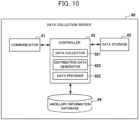
- FIG. 10 is a block diagram for explaining the configuration of the data collection server 60 according to Embodiment 2 of the present disclosure.
- the data collection server 60 includes a communicator 61, a controller 62, a data storage 63 that is an example of accumulation means, and an ancillary information database 64.
- the controller 62 further includes a distribution data generator 623 that is one example of distribution data generation means. That is, the configuration of the data collection server 60 illustrated in FIG. 10 is different from the above-described data collection server 60 of FIG. 5 in that the configuration illustrated in FIG. 10 further includes the distribution data generator 623 and the ancillary information database 64.
- the ancillary information database 64 is a database that stores ancillary information corresponding to a device (for example, device ID) such as the air conditioner 10, the lighting device 20, the temperature sensor 30, or the motion sensor 40.
- a device for example, device ID
- the ancillary information database 64 stores ancillary information corresponding to the manufacturer, model number and the like, as illustrated in FIG. 11 .
- Such additional information stored in the ancillary information database 64 has only the bare minimum content (items), for example, only the manufacturer, model number, and serial number.
- the data collector 621 collects device data from the device such as the air conditioner 10, the lighting device 20, the temperature sensor 30, or the motion sensor 40. That is, the data collector 621 collects only the above- described device data as illustrated in FIG. 3A .
- the distribution data generator 623 acquires, from the ancillary information database 64, the ancillary information corresponding to the device data collected by the data collector 621 and adds the ancillary information to the device data to generate distribution data as illustrated in FIG. 12 .
- the distribution data illustrated in FIG. 12 is described in JSON format, such a format is merely one example, and the data distribution may be described in another format such as XML format or CSV format.
- the distribution data generator 623 stores the generated distribution data in the data storage 63.
- the data provider 622 provides the corresponding distribution data to the data usage server 70 in response to a request from the data usage server 70.
- FIG. 13 is a flowchart illustrating one example of data transmission processing performed by the device such as the air conditioner 10, the lighting device 20, the temperature sensor 30, or the motion sensor 40, and data accumulation processing performed by the data collection server 60.
- the same reference numerals are assigned to the same processing content as the above-described processing in FIG. 8 .
- the device determines whether the data transmission condition is satisfied (step S101). When the device determines that the data transmission condition is not satisfied (No in step S101), the device stands by until the transmission condition is satisfied.
- the device determines whether the data transmission condition is determined to be satisfied (Yes in step S101).
- the device generates device data (step S102).
- the data generator 122 of the air conditioner 10 generates device data as illustrated in FIG. 3A in accordance with a state of the air conditioner 10.
- the device data is assumed to also include a device ID for identifying the device.
- the device transmits the generated device data to the data collection server 60 (Step S113).
- the communicator 11 of the air conditioner 10 transmits, to the data collection server 60 via the router 50, the device data generated in step S102.
- the data collection server 60 determines whether the device data is received (step S211). That is, the data collector 621 determines whether the communicator 61 receives the device data transmitted from the device.
- the data collection server 60 Upon determining that the device data is not received (No in step S211), the data collection server 60 stands by until the device data is received.
- the data collection server 60 adds the ancillary information to the device data to generate distribution data (step S212). That is, the distribution data generator 623 acquires, from the ancillary information database 64, the ancillary information corresponding to the device data received in step S211 and adds the ancillary information to the device data to generate distribution data as illustrated in FIG. 12 .
- the distribution data illustrated in FIG. 12 is described in JSON format, such a format is merely one example, and the distribution data may be described in another format such as XML format or CSV format.
- the data collection server 60 accumulates the distribution data (step S202). That is, the data collector 621 stores the distribution data generated in step S212 in the data storage 63.
- the distribution data including the device data and the ancillary information accumulate in the data collection server 60.
- the device only transmits the device data to the data collection server 60, thereby enabling a reduction of processing load, data traffic and the like.
- the data distribution system 1 according to Embodiment 2 can also use useful distribution data by performing the above-described processing illustrated in FIG. 9 . That is, the user can verify the validity, reliability and the like of the distribution data based on the ancillary information. Also, the user can properly use the distribution data based on the ancillary information. That is, since the ancillary information is added to the distribution data, the user can easily process or make proper use of the distribution data (device data).
- the device when calculating device data (for example, temperature data) included in distribution data acquired from different installation locations, significant figures may be appropriately determined in accordance with precision or resolution, or high-precision device data can be used for the determination, and conversely, the low-precision device data can be used only for displaying such device data.
- the device includes a plurality of sensors different in precision in order to measure the same physical quantity, since the ancillary information is added to the distribution data, the user can appropriately determine, in accordance with circumstances, which of the physical quantities measured by the sensors is appropriate for use. In that case, by the determination in accordance with circumstances, only useful distribution data can be used, and the data traffic can be also optimized.
- the data usage server 70 can provide various services in addition to the above-described watch-over processing. That is, the data usage server 70 can provide various types of services by using the ancillary information included in the distribution data provided from the data collection server 60 and building an algorithm optimized in accordance with the service.
- Embodiments 1 and 2 the case is described in which the data collection server 60 only accumulates (i) the distribution data collected from the device such as the air conditioner 10, the lighting device 20, the temperature sensor 30, or the motion sensor 40, or (ii) the distribution data generated on the data collection server 60 side.
- new distribution data may be generated and accumulated based on a plurality of accumulated distribution data values.
- Embodiment 3 is described that is characterized in that new distribution data is generated on the data collection server 60 side.
- Embodiment 3 of the present disclosure is the same to the above- described configuration illustrated in FIG. 1 .
- the configurations of the devices such as the air conditioner 10, the lighting device 20, the temperature sensor 30, and the motion sensor 40 are the same as the above-described configurations illustrated in FIG. 2 .
- the data generator 122 is configured to generate the distribution data as in Embodiment 1.
- the configuration of the data usage server 70 is the same as the above-described configuration illustrated in FIG. 7 .
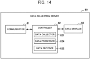
- FIG. 14 is a block diagram for explaining the configuration of the data collection server 60 according to Embodiment 3 of the present disclosure.
- the data collection server 60 is equipped with a communicator 61, a controller 62, and a data storage 63 that is one example of accumulation means.
- the controller 62 further includes a data processor 624 as one example of distribution data processing means, in addition to the configuration of the controller 62 illustrated in FIG. 5 .
- the data collector 621 collects distribution data from the device such as the air conditioner 10, the lighting device 20, the temperature sensor 30, or the motion sensor 40. That is, the data collector 621 collects the above-described distribution data as illustrated in FIGS. 3C and 4A and stores the distribution data in the data storage 63.
- the distribution data of the air conditioner 10 illustrated in FIG. 3C is collected, for example, at five-minute intervals
- the distribution data of the temperature sensor 30 illustrated in FIG. 4A is collected, for example, at one-minute intervals.
- the data processor 624 processes distribution data collected by the data collector 621 to generate new distribution data.
- the distribution data of the air conditioner 10 collected at 5-minute intervals is linearly interpolated to generate distribution data at 1-minute intervals to fill gaps.
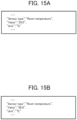
- the data processor 624 linearly interpolates the distribution data at a time five minutes ago as illustrated in FIG. 15A (a portion of the distribution data of the air conditioner 10 that is acquired five minutes ago) and the distribution data at the present time as illustrated in FIG. 15B (a portion of the distribution data of the air conditioner 10 that is acquired at the present time) to generate the distribution data at a time four minutes ago, at a time three minutes ago, at a time two minutes ago, and at a time one minute ago.
- the data processor 624 since the room temperature in the distribution data at the time five minutes ago illustrated in FIG. 15A is 25°C and the room temperature in the distribution data at the present time that is illustrated in FIG. 15B is 26°C, the data processor 624 generates, as illustrated in FIG. 15C , distribution data obtained by setting the room temperature at the time four minutes ago to 25.2°C, setting the room temperature at the time three minutes ago to 25.4°C, setting the room temperature at the time two minutes ago to 25.6°C, and setting the room temperature at the time one minute ago to 25.8°C. At this time, the data processor 624 sets precision (resolution) to " 1.0" in the distribution data illustrated in FIG. 15C to make the precision rough (that is, to reduce the precision for room temperature), and sets the processing content (processing) to " 12" to clarify that linear interpolation is performed.
- the data processor 624 may generate new distribution data by another process other than such linear interpolation. For example, the data processor 624 may calculate the average of the room temperature in the distribution data for a certain period (for example, a period from a time of 60 minutes before the present time to the present time) and newly generate the distribution data of the calculated average room temperature.
- the data processor 624 stores, in the data storage 63, the new distribution data generated by such processing.
- the data provider 622 provides the corresponding distribution data to the data usage server 70 in response to a request from the data usage server 70.
- FIG. 16 is a flowchart illustrating one example of data accumulation processing performed by the data collection server 60.
- the data transmission processing executed by the devices such as the air conditioner 10, the lighting device 20, the temperature sensor 30, and the motion sensor 40 is the same processing as in FIG. 8 and thus is omitted.
- the same reference numerals are assigned to the same processing contents as those of the above-described data accumulation processing of FIG. 8 .
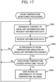
- FIG. 17 is a flowchart illustrating one example of room temperature monitoring processing performed by the data usage server 70.
- the data provision processing performed by the data collection server 60 is the same processing as that in FIG. 9 and thus is omitted.
- the data collection server 60 determines whether distribution data transmitted from the device is received (step S201). Upon determination that that distribution data is not received (No in step S201), the data collection server 60 stands by until the distribution data is received.
- the data collection server 60 determines whether the received distribution data is distribution data from the air conditioner 10 (step S222). For example, the data collector 621 determines whether the received data is distribution data of the air conditioner 10 collected at 5-minute intervals.
- the data collection server 60 Upon determination that the received data is not distribution data from the air conditioner 10 (No in step S222), the data collection server 60 makes the processing advance to step S202 described below.
- the data collection server 60 acquires the distribution data at the time five minutes ago (step S223). That is, the data processor 624 reads, from the data storage 63, the distribution data at the time five minutes ago for the air conditioner 10.
- the data collection server 60 calculates a room temperature that is interpolated every minute (step S224). For example, when the room temperature in the distribution data at the time five minutes ago that is acquired in step S223 is 25°C and the room temperature in the distribution data at the present time that is received in step S201 is 26°C, the data processor 624 calculates, by the linear interpolation, the room temperature at the time four minutes ago as 25.2°C, the room temperature at the time three minutes ago as 25.4°C, the room temperature at the time two minutes ago as 25.6°C, and the room temperature at the time one minute ago as 25.8°C.
- the data collection server 60 generates distribution data for each interpolated room temperature (step S225). For example, as illustrated in FIG. 15C , the data processor 624 generates the distribution data at the time four minutes ago, at the time three minutes ago, at the time two minutes ago, and at the time one minute ago. At this time, the data processor 624 sets the precision (resolution) to "1.0" in the distribution data illustrated in FIG. 15C to make the precision rough (that is to reduce the precision for room temperature), and sets the processing content (processing) to "12" to clarify that linear interpolation is performed.
- the data collection server 60 accumulates distribution data (step S202). That is, the data collector 621 stores, in the data storage 63, the distribution data received in step S201. Also, the data processor 624 stores, in the data storage 63, the distribution data newly generated in step S225.
- the data usage server 70 designates the contents of the ancillary information to request distribution data (step S501). For example, the data usage server 70 requests the distribution data from the data collection server 60 while designating the specific information (for example, serial numbers) of the air conditioner 10 and the temperature sensor 30 that are placed in the home (house H) whose room temperature is to be monitored.
- specific information for example, serial numbers
- the data usage server 70 receives the distribution data provided from the data collection server 60 (step S502).
- the data usage server 70 determines whether the precision of the room temperature indicated by the ancillary information of the received distribution data is higher than that of the reference (step S503). For example, the data analyzer 721 determines whether the precision (resolution) in the ancillary information is not greater than "0.1". Also, the precision (resolution) is described as "0.5" in the distribution data of the air conditioner 10 illustrated in FIG. 3C , the precision (resolution) is described as "1.0" in the interpolated distribution data of the air conditioner 10 illustrated in FIG. 15C , and the precision (resolution) is described as "0.1" in the distribution data of the temperature sensor 30 illustrated in FIG. 4A . Accordingly, only the precision of the room temperature in the distribution data of the temperature sensor 30 is determined to be higher than the reference.
- the data usage server 70 determines that the precision of the room temperature indicated by the ancillary information is not higher than the reference (No in step S503), the data usage server 70 returns to the processing to step S501 described above.
- the data usage server 70 determines whether the room temperature exceeds an upper limit value (step S504).
- the room temperature may be compared not only with the upper limit value as described above but also with a lower limit value.
- step S504 processing returns to step S501 described above.
- the data usage server 70 gives notice of abnormality of the room temperature by an email (step S505). That is, the service provider 722 sends an email to the registered user's address to give notice of the abnormality of the room temperature.
- the data usage server 70 may be configured to (i) accumulate the distribution data provided from the data collection server 60 and (ii) display a change in the room temperature in time series when an inquiry on the room temperature is made from a user's terminal (for example, a smartphone).
- the room temperature may be displayed using the distribution data of the temperature sensor 30 with high precision.
- the respective location and room temperature may be displayed together.
- the user's terminal can display, in time series at one-minute intervals, the room temperature measured by the temperature sensor 30 and the room temperature measured by the air conditioner 10.
- the distribution data including the device data and the ancillary information is appropriately processed and accumulated in the data collection server 60, and the useful data distribution is available by the room temperature monitoring processing illustrated in FIG. 17 . That is, since new distribution data is generated by processing, more detailed services can be provided to the user. Additionally, the user can verify the validity, reliability and the like of the distribution data based on the ancillary information. In addition, the user can properly use the distribution data based on the ancillary information. That is, since the ancillary information is added to the distribution data, the user can easily process or easily make proper use of the distribution data (device data).
- the device when calculating device data (for example, temperature data) included in distribution data acquired from different installation locations, significant figures can be appropriately determined in accordance with precision or resolution, and high-precision device data can be used for the determination and, on the contrary, the low-precision device data can be used only for displaying such device data.
- the user can appropriately determine, in accordance with circumstances, which of physical quantities measured by the sensors is to be used since the ancillary information is added to the distribution data. In this case, by the determination in accordance with circumstances, use is possible of useful distribution data alone and data traffic can be also optimized.
- the data usage server 70 can provide various services other than the room temperature monitoring processing described above.
- the data usage server 70 can provide various services by (i) using the ancillary information included in the distribution data provided from the data collection server 60 and (ii) building an algorithm optimized in accordance with the services.
- the program executed by the controllers 62 and 72 of the data collection server 60 and the data usage server 70 can be stored on a computer readable recording medium such as a compact disc-read only memory (CD-ROM), a digital versatile disc-read only memory (DVD-ROM), a magneto-optical disk (MO), a USB flash device, or a memory card, and then the recording medium storing the program can be distributed.
- a computer readable recording medium such as a compact disc-read only memory (CD-ROM), a digital versatile disc-read only memory (DVD-ROM), a magneto-optical disk (MO), a USB flash device, or a memory card
- the program may be installed in a dedicated or general-purpose computer, thereby enabling the computer to function as the data collection server 60 and the data usage server 70 of the above-described embodiments.
- the above-described program may be stored, in advance, in a storage device that is included in a server device on a communication network such as the Internet, and the program may be downloaded onto the computer, for example, by superimposing the program on a carrier wave.
- the above-described processing can be achieved by launching and executing the program while transferring the program via the communication network. Additionally, the above-described processing can be also achieved by (i) executing the whole of or a part of the program on the server device and (ii) executing the program while the computer is transmitting and receiving information on the processing via the communication network.
- OS operating system
- storage of only a portion other than the OSs in the above-described recording medium is permissible and such a recording medium may be distributed or the portion other than the OSs may be downloaded onto the computer.
- the present disclosure can be used with advantage for a data distribution system and a data provision method.
Landscapes
- Engineering & Computer Science (AREA)
- Theoretical Computer Science (AREA)
- Databases & Information Systems (AREA)
- General Physics & Mathematics (AREA)
- Physics & Mathematics (AREA)
- General Engineering & Computer Science (AREA)
- Data Mining & Analysis (AREA)
- Computing Systems (AREA)
- Computer Security & Cryptography (AREA)
- Software Systems (AREA)
- Selective Calling Equipment (AREA)
- Telephonic Communication Services (AREA)
- Information Retrieval, Db Structures And Fs Structures Therefor (AREA)
- Air Conditioning Control Device (AREA)
Claims (3)
- Datenverteilungssystem (1) zum Bereitstellen von Verteilungsdaten, die als ein Ziel für eine Verteilung dienen, wobei das Datenverteilungssystem (1) umfasst:eine Einrichtung (10);einen Datenerhebungsserver (60); undeinen Datennutzungsserver (70), wobeidie Einrichtung (10) ein Übertragungsmittel (11) zum Übertragen von Einrichtungsdaten umfasst, wobei der Datenerhebungsserver (60) umfasst:ein Erhebungsmittel (621) zum Erheben der von der Einrichtung (10) übertragenen Einrichtungsdaten, wobei die Einrichtung (10) eine Klimaanlage (10) ist, wobei die Klimaanlage (10) eine Temperaturmesseinheit umfasst, die in der Nähe einer Ansaugöffnung zum Ansaugen von Innenraumluft angeordnet ist und eingerichtet ist, eine Raumtemperatur zu messen, wobei die Einrichtungsdaten Daten sind, die einen Zustand der Klimaanlage (10) anzeigen, und wobei die Einrichtungsdaten einen Zustand einer Energieversorgung, einen Zustand eines Betriebsmodus, eine Einstelltemperatur und die Raumtemperatur enthalten;ein Bereitstellungsmittel (622) zum Bereitstellen, an den Datennutzungsserver (70), von Verteilungsdaten, welche die von dem Erhebungsmittel (621) erhobenen Einrichtungsdaten enthalten, und Zusatzinformationen, welche eine Genauigkeit der Einrichtungsdaten und einen Inhalt von Verarbeitung der Einrichtungsdaten enthalten; undein Verarbeitungsmittel (624) zum Erzeugen neuer Verteilungsdaten für Dateninterpolation durch Bezugnehmen auf eine Vielzahl der Verteilungsdaten,wobei das Verarbeitungsmittel (624) eine Genauigkeit für die Raumtemperatur in den Zusatzinformationen der erzeugten neuen Verteilungsdaten festlegt, niedriger zu sein als eine Genauigkeit für die Raumtemperatur in den Zusatzinformationen der referenzierten Verteilungsdaten, und ein Verfahren einschließlich linearer Interpolation auf den Inhalt von Verarbeitung in den Zusatzinformationen der erzeugten neuen Verteilungsdaten festlegt, undder Datennutzungsserver (70) ein Dienstbereitstellungsmittel (722) zur Bereitstellung eines Dienstes gemäß der Genauigkeit und dem Inhalt von Verarbeitung in den Zusatzinformationen unter Verwendung der vom Datenerhebungsserver (60) bereitgestellten Verteilungsdaten umfasst;wobei der Datennutzungsserver (70) eingerichtet ist, die vom Datenerhebungsserver (60) bereitgestellten Verteilungsdaten zu akkumulieren, und eine Änderung der Raumtemperatur in Zeitreihen anzuzeigen, wenn eine Abfrage der Raumtemperatur von einem Endgerät eines Benutzers erfolgt;wobei der Datennutzungsserver (70) ferner eingerichtet ist, zu bestimmen, ob die Genauigkeit der durch die Zusatzinformationen der empfangenen Verteilungsdaten angezeigten Raumtemperatur höher ist als die einer Referenz;wenn für die Genauigkeit der durch die Zusatzinformationen angezeigten Raumtemperatur bestimmt ist, höher zu sein als die Referenz, der Datennutzungsserver (70) eingerichtet ist, zu bestimmen, ob die Raumtemperatur einen oberen Grenzwert überschreitet; undwenn für die Raumtemperatur bestimmt ist, die obere Grenze zu überschreiten, der Datennutzungsserver (70) ferner eingerichtet ist, über Anomalie der Raumtemperatur zu benachrichtigen.
- Datenverteilungssystem (1) nach Anspruch 1, wobei
die Zusatzinformationen ferner zumindest eines von einer Zeit, einer Einheit, einer Auflösung, eines Herstellers oder einer Modellnummer enthalten. - Datenbereitstellungsverfahren, das von einer Servervorrichtung (60) zum Bereitstellen von Verteilungsdaten, die als ein Ziel für eine Verteilung dienen, und einem Datennutzungsserver (70) durchzuführen ist, wobei das Datenbereitstellungsverfahren umfasst:Erheben, durch die Servereinrichtung (60), von Einrichtungsdaten, die von einer Einrichtung (10) bezogen werden, wobei die Einrichtung (10) eine Klimaanlage (10) ist, wobei die Klimaanlage (10) eine Temperaturmesseinheit umfasst, die in der Nähe einer Ansaugöffnung zum Ansaugen von Innenraumluft angeordnet ist, und eingerichtet ist, eine Raumtemperatur zu messen, wobei die Einrichtungsdaten Daten sind, die einen Zustand der Klimaanlage (10) anzeigen, und wobei die Einrichtungsdaten einen Zustand einer Energieversorgung, einen Zustand eines Betriebsmodus, eine Einstelltemperatur und die Raumtemperatur umfassen;Bereitstellen, durch die Servereinrichtung (60) nach außerhalb, von Verteilungsdaten, welche die erhobenen Einrichtungsdaten enthalten, und Zusatzinformationen, enthaltend eine Genauigkeit der Einrichtungsdaten und einen Inhalt von Verarbeitung der Einrichtungsdaten; undErzeugen, durch die Servereinrichtung (60), neuer Verteilungsdaten für Dateninterpolation durch Bezugnehmen auf eine Vielzahl der Verteilungsdaten, wobeibeim Erzeugen, eine Genauigkeit für die Raumtemperatur in den Zusatzinformationen der erzeugten neuen Verteilungsdaten festgelegt wird, niedriger zu sein als eine Genauigkeit für die Raumtemperatur in den Zusatzinformationen der referenzierten Verteilungsdaten, und ein Verfahren einschließlich linearer Interpolation auf den Inhalt von Verarbeitung in den Zusatzinformationen der erzeugten neuen Verteilungsdaten festgelegt wird;wobei das Verfahren ferner umfasst:Bereitstellen, durch ein Dienstbereitstellungsmittel (722) des Datennutzungsservers (70), eines Dienstes gemäß der Genauigkeit und dem Inhalt von Verarbeitung in den Zusatzinformationen unter Verwendung der vom Datenerhebungsserver (60) bereitgestellten Verteilungsdaten;Akkumulieren, durch den Datennutzungsserver (70), der durch den Datenerhebungsserver (60) bereitgestellten Verteilungsdaten, undAnzeigen, durch den Datennutzungsserver (70), einer Änderung der Raumtemperatur in Zeitreihen anzeigt, wenn eine Abfrage der Raumtemperatur von einem Endgerät eines Benutzers erfolgt;wobei der Datennutzungsserver (70) ferner bestimmt, ob die Genauigkeit der durch die Zusatzinformationen der empfangenen Verteilungsdaten angezeigten Raumtemperatur höher ist als die einer Referenz;wenn für die Genauigkeit der Raumtemperatur, welche durch die Zusatzinformationen angezeigt ist, bestimmt ist, höher zu sein als die Referenz, der Datennutzungsserver (70) bestimmt, ob die Raumtemperatur einen oberen Grenzwert überschreitet; undwenn für die Raumtemperatur bestimmt ist, die obere Grenze zu überschreiten, der Datennutzungsserver (70) über eine Anomalie der Raumtemperatur benachrichtigt.
Applications Claiming Priority (1)
| Application Number | Priority Date | Filing Date | Title |
|---|---|---|---|
| PCT/JP2018/036322 WO2020065925A1 (ja) | 2018-09-28 | 2018-09-28 | サーバ装置、データ流通システム、データ提供方法、及び、プログラム |
Publications (3)
| Publication Number | Publication Date |
|---|---|
| EP3859544A1 EP3859544A1 (de) | 2021-08-04 |
| EP3859544A4 EP3859544A4 (de) | 2021-09-01 |
| EP3859544B1 true EP3859544B1 (de) | 2024-05-01 |
Family
ID=69950467
Family Applications (1)
| Application Number | Title | Priority Date | Filing Date |
|---|---|---|---|
| EP18935399.8A Active EP3859544B1 (de) | 2018-09-28 | 2018-09-28 | Servervorrichtung, datenverteilungssystem, datenbereitstellungsverfahren und programm |
Country Status (5)
| Country | Link |
|---|---|
| US (1) | US11741077B2 (de) |
| EP (1) | EP3859544B1 (de) |
| JP (1) | JP6984036B2 (de) |
| CN (1) | CN112703493B (de) |
| WO (1) | WO2020065925A1 (de) |
Families Citing this family (2)
| Publication number | Priority date | Publication date | Assignee | Title |
|---|---|---|---|---|
| US11836127B2 (en) * | 2021-04-02 | 2023-12-05 | Dell Products L.P. | Unique identification of metric values in telemetry reports |
| US20250200018A1 (en) * | 2022-03-16 | 2025-06-19 | Laplace System Co., Ltd. | Data structure containing identifier for numerical data, and numerical value management system using same |
Family Cites Families (25)
| Publication number | Priority date | Publication date | Assignee | Title |
|---|---|---|---|---|
| JP2002099817A (ja) * | 2000-09-22 | 2002-04-05 | Osaka Gas Co Ltd | 広告決定方法、提供情報決定システム、情報提供装置、及び記録媒体 |
| JP4883737B2 (ja) | 2000-10-30 | 2012-02-22 | キヤノン株式会社 | X線画像処理装置、x線画像処理方法および記憶媒体 |
| US8595161B2 (en) * | 2006-05-12 | 2013-11-26 | Vecna Technologies, Inc. | Method and system for determining a potential relationship between entities and relevance thereof |
| JP2009193433A (ja) * | 2008-02-15 | 2009-08-27 | Oki Electric Ind Co Ltd | 電気機器管理システム、電気機器管理サーバおよび電気機器管理方法 |
| WO2009125627A1 (ja) * | 2008-04-11 | 2009-10-15 | 三菱電機株式会社 | 機器状態検出装置及び機器状態検出方法並びに生活者異常検知装置、生活者異常検知システム及び生活者異常検知方法 |
| WO2009154484A2 (en) * | 2008-06-20 | 2009-12-23 | Business Intelligence Solutions Safe B.V. | Methods, apparatus and systems for data visualization and related applications |
| JP2011138317A (ja) * | 2009-12-28 | 2011-07-14 | Hitachi Solutions Ltd | プローブ情報管理システム |
| JP2013152557A (ja) * | 2012-01-24 | 2013-08-08 | Nippon Telegr & Teleph Corp <Ntt> | メタデータ付与装置、メタデータ付与方法およびメタデータ付与プログラム |
| WO2013159235A1 (en) * | 2012-04-27 | 2013-10-31 | Socovar S.E.C. | Wireless sensor network for measurement of electrical energy consumption |
| CN103517402B (zh) * | 2012-06-25 | 2018-04-13 | 北京大学深圳研究生院 | 一种面向对象形式化描述的无线传感网终端注册及控制方法 |
| EP2762877A1 (de) * | 2013-01-31 | 2014-08-06 | Sensirion AG | Kalibrierung eines chemischen Sensors in einer tragbaren elektronischen Vorrichtung |
| US9900171B2 (en) * | 2013-02-25 | 2018-02-20 | Qualcomm Incorporated | Methods to discover, configure, and leverage relationships in internet of things (IoT) networks |
| WO2014171469A1 (ja) * | 2013-04-18 | 2014-10-23 | シャープ株式会社 | 情報管理装置 |
| US10990894B2 (en) * | 2013-07-11 | 2021-04-27 | Neura, Inc. | Situation forecast mechanisms for internet of things integration platform |
| JP5530019B1 (ja) * | 2013-11-01 | 2014-06-25 | 株式会社日立パワーソリューションズ | 異常予兆検知システム及び異常予兆検知方法 |
| EP3101906A4 (de) * | 2014-01-29 | 2017-08-30 | Nec Corporation | Kommunikationssystem, gemeinsame dienststeuerungsvorrichtung, datensammelverfahren und nichttransitorisches computerlesbares medium |
| JP2017513152A (ja) * | 2014-02-10 | 2017-05-25 | イウン、スツ・ファンIUN, Sut Fan | 生活のシステム |
| JP2015226102A (ja) * | 2014-05-26 | 2015-12-14 | オムロン株式会社 | 仮想センサのメタデータ構造 |
| US9690361B2 (en) * | 2014-12-24 | 2017-06-27 | Intel Corporation | Low-power context-aware control for analog frontend |
| US20180097886A1 (en) | 2015-03-27 | 2018-04-05 | Nec Corporation | Sensor network system |
| JP2016212498A (ja) * | 2015-04-30 | 2016-12-15 | シャープ株式会社 | データを収集するシステム、サーバ装置、通信機器、データを収集する方法およびプログラム |
| KR102292990B1 (ko) * | 2015-11-20 | 2021-08-26 | 삼성전자 주식회사 | 상태 관련 정보 공유 방법 및 장치 |
| US10607145B2 (en) * | 2015-11-23 | 2020-03-31 | International Business Machines Corporation | Detection algorithms for distributed emission sources of abnormal events |
| CN107551698B (zh) * | 2017-08-31 | 2023-08-08 | 广东美的环境电器制造有限公司 | 净化器、信息处理方法及计算机存储介质 |
| US10962945B2 (en) * | 2017-09-27 | 2021-03-30 | Johnson Controls Technology Company | Building management system with integration of data into smart entities |
-
2018
- 2018-09-28 EP EP18935399.8A patent/EP3859544B1/de active Active
- 2018-09-28 US US17/263,295 patent/US11741077B2/en active Active
- 2018-09-28 WO PCT/JP2018/036322 patent/WO2020065925A1/ja not_active Ceased
- 2018-09-28 CN CN201880097657.0A patent/CN112703493B/zh active Active
- 2018-09-28 JP JP2020547800A patent/JP6984036B2/ja active Active
Also Published As
| Publication number | Publication date |
|---|---|
| JPWO2020065925A1 (ja) | 2021-02-15 |
| WO2020065925A1 (ja) | 2020-04-02 |
| US11741077B2 (en) | 2023-08-29 |
| EP3859544A1 (de) | 2021-08-04 |
| US20210149877A1 (en) | 2021-05-20 |
| EP3859544A4 (de) | 2021-09-01 |
| JP6984036B2 (ja) | 2021-12-17 |
| CN112703493A (zh) | 2021-04-23 |
| CN112703493B (zh) | 2024-09-24 |
Similar Documents
| Publication | Publication Date | Title |
|---|---|---|
| JP7034209B2 (ja) | 空調機を管理する方法及び装置 | |
| KR102475642B1 (ko) | 전자 장치 및 이의 냉난방 제어 방법 | |
| CN107003019B (zh) | 用于预测hvac过滤器更换的系统和方法 | |
| US10498585B2 (en) | Sensor data analytics and alarm management | |
| US10216160B2 (en) | Matching a building automation algorithm to a building automation system | |
| US20160103442A1 (en) | Central control apparatus for controlling facilities, facility control system comprising the same, and facility control method | |
| US20160103475A1 (en) | Central control apparatus for controlling facilities, facility control system including the same, and method of controlling facilities | |
| KR101870250B1 (ko) | 비침투식 부하전력량 측정 장치 및 방법 | |
| US10817630B2 (en) | Apparatus and method for analyzing buildings | |
| US20140343698A1 (en) | Device control apparatus, device control method, and device control system | |
| KR20070095712A (ko) | 실내 환경 관리 시스템 및 이를 이용하는 실내 환경 관리방법 | |
| EP3859544B1 (de) | Servervorrichtung, datenverteilungssystem, datenbereitstellungsverfahren und programm | |
| CN106255987A (zh) | 建筑物围层和内部分级系统和方法 | |
| US20170330246A1 (en) | System, user managing server, and method of providing user customized advertisement | |
| JP2020086910A (ja) | 空調システム管理装置、データ提供システム、データ提供方法、及び、プログラム | |
| Mandurano et al. | House Away: A home management system | |
| JP2012048409A (ja) | 電力管理システムおよび管理サーバ | |
| US10503192B2 (en) | Energy consumption modeling | |
| JP2016181026A (ja) | 在宅状況判定装置、方法及びプログラム | |
| JP2020041782A (ja) | 空気調和システム | |
| KR20230093874A (ko) | 보일러 관리 장치 및 빅데이터 기반 보일러의 예측 모델 생성 방법 | |
| JP5914866B2 (ja) | 省エネルギ診断システム、省エネルギ診断方法 | |
| CA3070670C (en) | A method and system for automatic detection of inefficient household thermal insulation | |
| JP5672579B2 (ja) | 省エネルギ診断システム | |
| CN121720762A (zh) | 空调系统运维方法、装置、电子设备及存储介质 |
Legal Events
| Date | Code | Title | Description |
|---|---|---|---|
| STAA | Information on the status of an ep patent application or granted ep patent |
Free format text: STATUS: THE INTERNATIONAL PUBLICATION HAS BEEN MADE |
|
| PUAI | Public reference made under article 153(3) epc to a published international application that has entered the european phase |
Free format text: ORIGINAL CODE: 0009012 |
|
| STAA | Information on the status of an ep patent application or granted ep patent |
Free format text: STATUS: REQUEST FOR EXAMINATION WAS MADE |
|
| REG | Reference to a national code |
Ref country code: DE Ref legal event code: R079 Free format text: PREVIOUS MAIN CLASS: G06F0016000000 Ipc: G06F0016800000 Ref country code: DE Ref legal event code: R079 Ref document number: 602018069148 Country of ref document: DE Free format text: PREVIOUS MAIN CLASS: G06F0016000000 Ipc: G06F0016800000 |
|
| 17P | Request for examination filed |
Effective date: 20210308 |
|
| AK | Designated contracting states |
Kind code of ref document: A1 Designated state(s): AL AT BE BG CH CY CZ DE DK EE ES FI FR GB GR HR HU IE IS IT LI LT LU LV MC MK MT NL NO PL PT RO RS SE SI SK SM TR |
|
| A4 | Supplementary search report drawn up and despatched |
Effective date: 20210804 |
|
| RIC1 | Information provided on ipc code assigned before grant |
Ipc: G06F 16/80 20190101AFI20210729BHEP |
|
| DAV | Request for validation of the european patent (deleted) | ||
| DAX | Request for extension of the european patent (deleted) | ||
| STAA | Information on the status of an ep patent application or granted ep patent |
Free format text: STATUS: EXAMINATION IS IN PROGRESS |
|
| 17Q | First examination report despatched |
Effective date: 20220718 |
|
| GRAP | Despatch of communication of intention to grant a patent |
Free format text: ORIGINAL CODE: EPIDOSNIGR1 |
|
| STAA | Information on the status of an ep patent application or granted ep patent |
Free format text: STATUS: GRANT OF PATENT IS INTENDED |
|
| INTG | Intention to grant announced |
Effective date: 20240112 |
|
| GRAS | Grant fee paid |
Free format text: ORIGINAL CODE: EPIDOSNIGR3 |
|
| GRAA | (expected) grant |
Free format text: ORIGINAL CODE: 0009210 |
|
| STAA | Information on the status of an ep patent application or granted ep patent |
Free format text: STATUS: THE PATENT HAS BEEN GRANTED |
|
| AK | Designated contracting states |
Kind code of ref document: B1 Designated state(s): AL AT BE BG CH CY CZ DE DK EE ES FI FR GB GR HR HU IE IS IT LI LT LU LV MC MK MT NL NO PL PT RO RS SE SI SK SM TR |
|
| REG | Reference to a national code |
Ref country code: GB Ref legal event code: FG4D |
|
| REG | Reference to a national code |
Ref country code: CH Ref legal event code: EP |
|
| REG | Reference to a national code |
Ref country code: DE Ref legal event code: R096 Ref document number: 602018069148 Country of ref document: DE |
|
| REG | Reference to a national code |
Ref country code: IE Ref legal event code: FG4D |
|
| REG | Reference to a national code |
Ref country code: LT Ref legal event code: MG9D |
|
| REG | Reference to a national code |
Ref country code: NL Ref legal event code: MP Effective date: 20240501 |
|
| PG25 | Lapsed in a contracting state [announced via postgrant information from national office to epo] |
Ref country code: IS Free format text: LAPSE BECAUSE OF FAILURE TO SUBMIT A TRANSLATION OF THE DESCRIPTION OR TO PAY THE FEE WITHIN THE PRESCRIBED TIME-LIMIT Effective date: 20240901 |
|
| PG25 | Lapsed in a contracting state [announced via postgrant information from national office to epo] |
Ref country code: BG Free format text: LAPSE BECAUSE OF FAILURE TO SUBMIT A TRANSLATION OF THE DESCRIPTION OR TO PAY THE FEE WITHIN THE PRESCRIBED TIME-LIMIT Effective date: 20240501 |
|
| PG25 | Lapsed in a contracting state [announced via postgrant information from national office to epo] |
Ref country code: HR Free format text: LAPSE BECAUSE OF FAILURE TO SUBMIT A TRANSLATION OF THE DESCRIPTION OR TO PAY THE FEE WITHIN THE PRESCRIBED TIME-LIMIT Effective date: 20240501 Ref country code: FI Free format text: LAPSE BECAUSE OF FAILURE TO SUBMIT A TRANSLATION OF THE DESCRIPTION OR TO PAY THE FEE WITHIN THE PRESCRIBED TIME-LIMIT Effective date: 20240501 |
|
| PG25 | Lapsed in a contracting state [announced via postgrant information from national office to epo] |
Ref country code: GR Free format text: LAPSE BECAUSE OF FAILURE TO SUBMIT A TRANSLATION OF THE DESCRIPTION OR TO PAY THE FEE WITHIN THE PRESCRIBED TIME-LIMIT Effective date: 20240802 |
|
| PG25 | Lapsed in a contracting state [announced via postgrant information from national office to epo] |
Ref country code: PT Free format text: LAPSE BECAUSE OF FAILURE TO SUBMIT A TRANSLATION OF THE DESCRIPTION OR TO PAY THE FEE WITHIN THE PRESCRIBED TIME-LIMIT Effective date: 20240902 |
|
| REG | Reference to a national code |
Ref country code: AT Ref legal event code: MK05 Ref document number: 1683368 Country of ref document: AT Kind code of ref document: T Effective date: 20240501 |
|
| PG25 | Lapsed in a contracting state [announced via postgrant information from national office to epo] |
Ref country code: NL Free format text: LAPSE BECAUSE OF FAILURE TO SUBMIT A TRANSLATION OF THE DESCRIPTION OR TO PAY THE FEE WITHIN THE PRESCRIBED TIME-LIMIT Effective date: 20240501 |
|
| PG25 | Lapsed in a contracting state [announced via postgrant information from national office to epo] |
Ref country code: ES Free format text: LAPSE BECAUSE OF FAILURE TO SUBMIT A TRANSLATION OF THE DESCRIPTION OR TO PAY THE FEE WITHIN THE PRESCRIBED TIME-LIMIT Effective date: 20240501 |
|
| PG25 | Lapsed in a contracting state [announced via postgrant information from national office to epo] |
Ref country code: AT Free format text: LAPSE BECAUSE OF FAILURE TO SUBMIT A TRANSLATION OF THE DESCRIPTION OR TO PAY THE FEE WITHIN THE PRESCRIBED TIME-LIMIT Effective date: 20240501 |
|
| PG25 | Lapsed in a contracting state [announced via postgrant information from national office to epo] |
Ref country code: PL Free format text: LAPSE BECAUSE OF FAILURE TO SUBMIT A TRANSLATION OF THE DESCRIPTION OR TO PAY THE FEE WITHIN THE PRESCRIBED TIME-LIMIT Effective date: 20240501 |
|
| PG25 | Lapsed in a contracting state [announced via postgrant information from national office to epo] |
Ref country code: LV Free format text: LAPSE BECAUSE OF FAILURE TO SUBMIT A TRANSLATION OF THE DESCRIPTION OR TO PAY THE FEE WITHIN THE PRESCRIBED TIME-LIMIT Effective date: 20240501 |
|
| PG25 | Lapsed in a contracting state [announced via postgrant information from national office to epo] |
Ref country code: PT Free format text: LAPSE BECAUSE OF FAILURE TO SUBMIT A TRANSLATION OF THE DESCRIPTION OR TO PAY THE FEE WITHIN THE PRESCRIBED TIME-LIMIT Effective date: 20240902 Ref country code: PL Free format text: LAPSE BECAUSE OF FAILURE TO SUBMIT A TRANSLATION OF THE DESCRIPTION OR TO PAY THE FEE WITHIN THE PRESCRIBED TIME-LIMIT Effective date: 20240501 Ref country code: NO Free format text: LAPSE BECAUSE OF FAILURE TO SUBMIT A TRANSLATION OF THE DESCRIPTION OR TO PAY THE FEE WITHIN THE PRESCRIBED TIME-LIMIT Effective date: 20240801 Ref country code: NL Free format text: LAPSE BECAUSE OF FAILURE TO SUBMIT A TRANSLATION OF THE DESCRIPTION OR TO PAY THE FEE WITHIN THE PRESCRIBED TIME-LIMIT Effective date: 20240501 Ref country code: LV Free format text: LAPSE BECAUSE OF FAILURE TO SUBMIT A TRANSLATION OF THE DESCRIPTION OR TO PAY THE FEE WITHIN THE PRESCRIBED TIME-LIMIT Effective date: 20240501 Ref country code: IS Free format text: LAPSE BECAUSE OF FAILURE TO SUBMIT A TRANSLATION OF THE DESCRIPTION OR TO PAY THE FEE WITHIN THE PRESCRIBED TIME-LIMIT Effective date: 20240901 Ref country code: HR Free format text: LAPSE BECAUSE OF FAILURE TO SUBMIT A TRANSLATION OF THE DESCRIPTION OR TO PAY THE FEE WITHIN THE PRESCRIBED TIME-LIMIT Effective date: 20240501 Ref country code: GR Free format text: LAPSE BECAUSE OF FAILURE TO SUBMIT A TRANSLATION OF THE DESCRIPTION OR TO PAY THE FEE WITHIN THE PRESCRIBED TIME-LIMIT Effective date: 20240802 Ref country code: FI Free format text: LAPSE BECAUSE OF FAILURE TO SUBMIT A TRANSLATION OF THE DESCRIPTION OR TO PAY THE FEE WITHIN THE PRESCRIBED TIME-LIMIT Effective date: 20240501 Ref country code: ES Free format text: LAPSE BECAUSE OF FAILURE TO SUBMIT A TRANSLATION OF THE DESCRIPTION OR TO PAY THE FEE WITHIN THE PRESCRIBED TIME-LIMIT Effective date: 20240501 Ref country code: BG Free format text: LAPSE BECAUSE OF FAILURE TO SUBMIT A TRANSLATION OF THE DESCRIPTION OR TO PAY THE FEE WITHIN THE PRESCRIBED TIME-LIMIT Effective date: 20240501 Ref country code: AT Free format text: LAPSE BECAUSE OF FAILURE TO SUBMIT A TRANSLATION OF THE DESCRIPTION OR TO PAY THE FEE WITHIN THE PRESCRIBED TIME-LIMIT Effective date: 20240501 Ref country code: RS Free format text: LAPSE BECAUSE OF FAILURE TO SUBMIT A TRANSLATION OF THE DESCRIPTION OR TO PAY THE FEE WITHIN THE PRESCRIBED TIME-LIMIT Effective date: 20240801 |
|
| PG25 | Lapsed in a contracting state [announced via postgrant information from national office to epo] |
Ref country code: DK Free format text: LAPSE BECAUSE OF FAILURE TO SUBMIT A TRANSLATION OF THE DESCRIPTION OR TO PAY THE FEE WITHIN THE PRESCRIBED TIME-LIMIT Effective date: 20240501 |
|
| PG25 | Lapsed in a contracting state [announced via postgrant information from national office to epo] |
Ref country code: EE Free format text: LAPSE BECAUSE OF FAILURE TO SUBMIT A TRANSLATION OF THE DESCRIPTION OR TO PAY THE FEE WITHIN THE PRESCRIBED TIME-LIMIT Effective date: 20240501 |
|
| PG25 | Lapsed in a contracting state [announced via postgrant information from national office to epo] |
Ref country code: CZ Free format text: LAPSE BECAUSE OF FAILURE TO SUBMIT A TRANSLATION OF THE DESCRIPTION OR TO PAY THE FEE WITHIN THE PRESCRIBED TIME-LIMIT Effective date: 20240501 |
|
| PG25 | Lapsed in a contracting state [announced via postgrant information from national office to epo] |
Ref country code: RO Free format text: LAPSE BECAUSE OF FAILURE TO SUBMIT A TRANSLATION OF THE DESCRIPTION OR TO PAY THE FEE WITHIN THE PRESCRIBED TIME-LIMIT Effective date: 20240501 Ref country code: SK Free format text: LAPSE BECAUSE OF FAILURE TO SUBMIT A TRANSLATION OF THE DESCRIPTION OR TO PAY THE FEE WITHIN THE PRESCRIBED TIME-LIMIT Effective date: 20240501 |
|
| PG25 | Lapsed in a contracting state [announced via postgrant information from national office to epo] |
Ref country code: SM Free format text: LAPSE BECAUSE OF FAILURE TO SUBMIT A TRANSLATION OF THE DESCRIPTION OR TO PAY THE FEE WITHIN THE PRESCRIBED TIME-LIMIT Effective date: 20240501 |
|
| PG25 | Lapsed in a contracting state [announced via postgrant information from national office to epo] |
Ref country code: SM Free format text: LAPSE BECAUSE OF FAILURE TO SUBMIT A TRANSLATION OF THE DESCRIPTION OR TO PAY THE FEE WITHIN THE PRESCRIBED TIME-LIMIT Effective date: 20240501 Ref country code: SK Free format text: LAPSE BECAUSE OF FAILURE TO SUBMIT A TRANSLATION OF THE DESCRIPTION OR TO PAY THE FEE WITHIN THE PRESCRIBED TIME-LIMIT Effective date: 20240501 Ref country code: RO Free format text: LAPSE BECAUSE OF FAILURE TO SUBMIT A TRANSLATION OF THE DESCRIPTION OR TO PAY THE FEE WITHIN THE PRESCRIBED TIME-LIMIT Effective date: 20240501 Ref country code: EE Free format text: LAPSE BECAUSE OF FAILURE TO SUBMIT A TRANSLATION OF THE DESCRIPTION OR TO PAY THE FEE WITHIN THE PRESCRIBED TIME-LIMIT Effective date: 20240501 Ref country code: DK Free format text: LAPSE BECAUSE OF FAILURE TO SUBMIT A TRANSLATION OF THE DESCRIPTION OR TO PAY THE FEE WITHIN THE PRESCRIBED TIME-LIMIT Effective date: 20240501 Ref country code: CZ Free format text: LAPSE BECAUSE OF FAILURE TO SUBMIT A TRANSLATION OF THE DESCRIPTION OR TO PAY THE FEE WITHIN THE PRESCRIBED TIME-LIMIT Effective date: 20240501 |
|
| REG | Reference to a national code |
Ref country code: DE Ref legal event code: R097 Ref document number: 602018069148 Country of ref document: DE |
|
| PG25 | Lapsed in a contracting state [announced via postgrant information from national office to epo] |
Ref country code: IT Free format text: LAPSE BECAUSE OF FAILURE TO SUBMIT A TRANSLATION OF THE DESCRIPTION OR TO PAY THE FEE WITHIN THE PRESCRIBED TIME-LIMIT Effective date: 20240501 |
|
| PLBE | No opposition filed within time limit |
Free format text: ORIGINAL CODE: 0009261 |
|
| STAA | Information on the status of an ep patent application or granted ep patent |
Free format text: STATUS: NO OPPOSITION FILED WITHIN TIME LIMIT |
|
| 26N | No opposition filed |
Effective date: 20250204 |
|
| PG25 | Lapsed in a contracting state [announced via postgrant information from national office to epo] |
Ref country code: MC Free format text: LAPSE BECAUSE OF FAILURE TO SUBMIT A TRANSLATION OF THE DESCRIPTION OR TO PAY THE FEE WITHIN THE PRESCRIBED TIME-LIMIT Effective date: 20240501 Ref country code: SI Free format text: LAPSE BECAUSE OF FAILURE TO SUBMIT A TRANSLATION OF THE DESCRIPTION OR TO PAY THE FEE WITHIN THE PRESCRIBED TIME-LIMIT Effective date: 20240501 |
|
| REG | Reference to a national code |
Ref country code: CH Ref legal event code: PL |
|
| PG25 | Lapsed in a contracting state [announced via postgrant information from national office to epo] |
Ref country code: LU Free format text: LAPSE BECAUSE OF NON-PAYMENT OF DUE FEES Effective date: 20240928 |
|
| REG | Reference to a national code |
Ref country code: BE Ref legal event code: MM Effective date: 20240930 |
|
| PG25 | Lapsed in a contracting state [announced via postgrant information from national office to epo] |
Ref country code: BE Free format text: LAPSE BECAUSE OF NON-PAYMENT OF DUE FEES Effective date: 20240930 |
|
| PG25 | Lapsed in a contracting state [announced via postgrant information from national office to epo] |
Ref country code: CH Free format text: LAPSE BECAUSE OF NON-PAYMENT OF DUE FEES Effective date: 20240930 |
|
| PG25 | Lapsed in a contracting state [announced via postgrant information from national office to epo] |
Ref country code: IE Free format text: LAPSE BECAUSE OF NON-PAYMENT OF DUE FEES Effective date: 20240928 |
|
| PG25 | Lapsed in a contracting state [announced via postgrant information from national office to epo] |
Ref country code: SE Free format text: LAPSE BECAUSE OF FAILURE TO SUBMIT A TRANSLATION OF THE DESCRIPTION OR TO PAY THE FEE WITHIN THE PRESCRIBED TIME-LIMIT Effective date: 20240501 |
|
| PGFP | Annual fee paid to national office [announced via postgrant information from national office to epo] |
Ref country code: DE Payment date: 20250805 Year of fee payment: 8 |
|
| PGFP | Annual fee paid to national office [announced via postgrant information from national office to epo] |
Ref country code: GB Payment date: 20250807 Year of fee payment: 8 |
|
| PGFP | Annual fee paid to national office [announced via postgrant information from national office to epo] |
Ref country code: FR Payment date: 20250808 Year of fee payment: 8 |
|
| PG25 | Lapsed in a contracting state [announced via postgrant information from national office to epo] |
Ref country code: CY Free format text: LAPSE BECAUSE OF FAILURE TO SUBMIT A TRANSLATION OF THE DESCRIPTION OR TO PAY THE FEE WITHIN THE PRESCRIBED TIME-LIMIT; INVALID AB INITIO Effective date: 20180928 |
|
| PG25 | Lapsed in a contracting state [announced via postgrant information from national office to epo] |
Ref country code: HU Free format text: LAPSE BECAUSE OF FAILURE TO SUBMIT A TRANSLATION OF THE DESCRIPTION OR TO PAY THE FEE WITHIN THE PRESCRIBED TIME-LIMIT; INVALID AB INITIO Effective date: 20180928 |