EP3859449A1 - Cordon conducteur de spiral - Google Patents
Cordon conducteur de spiral Download PDFInfo
- Publication number
- EP3859449A1 EP3859449A1 EP20154530.8A EP20154530A EP3859449A1 EP 3859449 A1 EP3859449 A1 EP 3859449A1 EP 20154530 A EP20154530 A EP 20154530A EP 3859449 A1 EP3859449 A1 EP 3859449A1
- Authority
- EP
- European Patent Office
- Prior art keywords
- electrically conductive
- conductive layer
- watch
- deposition method
- hairspring
- Prior art date
- Legal status (The legal status is an assumption and is not a legal conclusion. Google has not performed a legal analysis and makes no representation as to the accuracy of the status listed.)
- Granted
Links
Images
Classifications
-
- G—PHYSICS
- G04—HOROLOGY
- G04B—MECHANICALLY-DRIVEN CLOCKS OR WATCHES; MECHANICAL PARTS OF CLOCKS OR WATCHES IN GENERAL; TIME PIECES USING THE POSITION OF THE SUN, MOON OR STARS
- G04B17/00—Mechanisms for stabilising frequency
- G04B17/04—Oscillators acting by spring tension
- G04B17/06—Oscillators with hairsprings, e.g. balance
- G04B17/066—Manufacture of the spiral spring
-
- G—PHYSICS
- G04—HOROLOGY
- G04D—APPARATUS OR TOOLS SPECIALLY DESIGNED FOR MAKING OR MAINTAINING CLOCKS OR WATCHES
- G04D3/00—Watchmakers' or watch-repairers' machines or tools for working materials
- G04D3/0074—Watchmakers' or watch-repairers' machines or tools for working materials for treatment of the material, e.g. surface treatment
- G04D3/0089—Watchmakers' or watch-repairers' machines or tools for working materials for treatment of the material, e.g. surface treatment for components of the regulating mechanism, e.g. coil springs
-
- G—PHYSICS
- G04—HOROLOGY
- G04B—MECHANICALLY-DRIVEN CLOCKS OR WATCHES; MECHANICAL PARTS OF CLOCKS OR WATCHES IN GENERAL; TIME PIECES USING THE POSITION OF THE SUN, MOON OR STARS
- G04B17/00—Mechanisms for stabilising frequency
- G04B17/32—Component parts or constructional details, e.g. collet, stud, virole or piton
- G04B17/325—Component parts or constructional details, e.g. collet, stud, virole or piton for fastening the hairspring in a fixed position, e.g. using a block
-
- B—PERFORMING OPERATIONS; TRANSPORTING
- B05—SPRAYING OR ATOMISING IN GENERAL; APPLYING FLUENT MATERIALS TO SURFACES, IN GENERAL
- B05D—PROCESSES FOR APPLYING FLUENT MATERIALS TO SURFACES, IN GENERAL
- B05D1/00—Processes for applying liquids or other fluent materials
- B05D1/02—Processes for applying liquids or other fluent materials performed by spraying
-
- C—CHEMISTRY; METALLURGY
- C23—COATING METALLIC MATERIAL; COATING MATERIAL WITH METALLIC MATERIAL; CHEMICAL SURFACE TREATMENT; DIFFUSION TREATMENT OF METALLIC MATERIAL; COATING BY VACUUM EVAPORATION, BY SPUTTERING, BY ION IMPLANTATION OR BY CHEMICAL VAPOUR DEPOSITION, IN GENERAL; INHIBITING CORROSION OF METALLIC MATERIAL OR INCRUSTATION IN GENERAL
- C23C—COATING METALLIC MATERIAL; COATING MATERIAL WITH METALLIC MATERIAL; SURFACE TREATMENT OF METALLIC MATERIAL BY DIFFUSION INTO THE SURFACE, BY CHEMICAL CONVERSION OR SUBSTITUTION; COATING BY VACUUM EVAPORATION, BY SPUTTERING, BY ION IMPLANTATION OR BY CHEMICAL VAPOUR DEPOSITION, IN GENERAL
- C23C24/00—Coating starting from inorganic powder
- C23C24/02—Coating starting from inorganic powder by application of pressure only
- C23C24/04—Impact or kinetic deposition of particles
-
- H—ELECTRICITY
- H05—ELECTRIC TECHNIQUES NOT OTHERWISE PROVIDED FOR
- H05F—STATIC ELECTRICITY; NATURALLY-OCCURRING ELECTRICITY
- H05F3/00—Carrying-off electrostatic charges
Definitions
- the present invention relates to an oscillating system for a clockwork movement.
- the present invention relates in particular to an oscillating system comprising a clock hairspring from which electrostatic charges can be eliminated.
- the material used for making the balance springs is usually an alloy based on iron, cobalt, nickel and chromium. Ductile, such an alloy must resist corrosion. Recent developments suggest making the balance springs out of silicon. Due to their very small dimensions and the friction with the air and between the turns, the spirals tend to become charged with static electricity, so that the turns stick to each other. The balance springs are then unusable as they are.
- the current methods aiming to discharge the electrostatic charges in the movement via the eyebolt involve an electrically conductive adhesive binding the eyebolt and balance spring. It is generally the mixture of a photo- or UV-curable adhesive and conductive particles. But these particles interfere with the crosslinking of the whole. This can lead to partial crosslinking and therefore piton-hairspring separation, which is detrimental to the operation of the oscillator.
- Another solution is to increase the crosslinking time significantly, but this goes against industrial production rates.
- the electrostatic charges can be located elsewhere than on the hairspring but in the environment close to the latter, for example a component made of insulating material initially charged during assembly or charged during movement.
- the present invention provides an oscillating system for a clockwork movement comprising a clockwork balance spring from which electrostatic charges can be eliminated.
- said watch hairspring comprises at least one inner coil fixed by a ferrule and at least one outer coil fixed by said eyebolt.
- said at least one first electrically conductive layer is deposited on the outside of said peak.
- said at least one first electrically conductive layer can be easily deposited.
- the deposition of said first electrically conductive layer is carried out by an atomizer.
- said atomizer comprises said at least one first electroconductive layer in liquid form surrounded by a sheathing gas so as to be unidirectional.
- said atomizer is unidirectional.
- said first electrically conductive layer comprises a continuous electrically conductive layer and / or a plurality of discrete electrically conductive layers so as to form a continuous electrically conductive layer.
- said at least one dimension is the length of said watch hairspring.
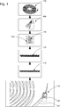
- the figure 1 illustrates a method of depositing 500 of an electrically conductive layer on an oscillating system 100 of a watch movement comprising a watch balance spring 101 with at least one inner coil fixed by a ferrule and at least one outer coil 105 fixed by a stud 102.
- One of the steps of said deposition process 500 is the supply 510 of said oscillating system 100. This is followed by the deposition of at least one first electrically conductive layer 110 by an atomizer 900 electrically connecting said at least one outer coil 105 and said pin 102. . preferably, said first electrically conductive layer 110 includes a continuous electrically conductive layer 111 and / or a plurality of discrete electrically conductive layers 115 so as to form a continuous electrically conductive layer 111.
- Said at least one first electrically conductive layer 110 more particularly, said continuous electrically conductive layer 111 is deposited and / or said plurality of discrete electrically conductive layers 115 are deposited on the outside of said peak 102, more exactly on the part of said peak 102 being on the outside. of said watch hairspring 101 because it is easier to reach than the part which faces the turns of said watch hairspring 101.
- Said atomizer 900 is configured to deposit said at least one first electroconductive layer 110 in liquid form surrounded by a sheath gas 119 so as to be unidirectional and therefore deposit said first electroconductive layer 110 on said at least one dimension, preferably the length of said watch balance spring 101, and representing at least 1%, in particular 5%, preferably 10% and / or at most 90%, in particular at most 75%, preferably at most 50% of at least one dimension of said watch balance spring 101.
- said atomizer 900 being unidirectional, the deposition of said at least one first electroconductive layer 110 may only partially cover the width of said watch hairspring 101 but perhaps not the whole of the width of said watch hairspring 101 which makes it possible to avoid a change in characteristic of said watch balance spring 101 such as for example its inertia or its frequency, or a modification of its elastic response.
- the deposition process is economical by virtue of its simplicity, and the little material deposited.
- this deposition process does not expose employees to potentially dangerous particles during said preparation of these glues or during deposition due to their inhalation. because the spraying is rarely directional or even unidirectional.
- Another disadvantage to conventional spraying is that this can pollute nearby moving components such as the escapement or the balance axle and therefore disrupt their tribological functions.
Landscapes
- Physics & Mathematics (AREA)
- General Physics & Mathematics (AREA)
- Chemical & Material Sciences (AREA)
- Engineering & Computer Science (AREA)
- Chemical Kinetics & Catalysis (AREA)
- Materials Engineering (AREA)
- Mechanical Engineering (AREA)
- Metallurgy (AREA)
- Organic Chemistry (AREA)
- Manufacturing & Machinery (AREA)
- Springs (AREA)
- Application Of Or Painting With Fluid Materials (AREA)
Abstract
Description
- La présente invention concerne un système oscillant pour mouvement d'horlogerie. La présente invention concerne en particulier un système oscillant comprenant un spiral horloger duquel les charges électrostatiques peuvent être éliminées.
- Il est connu dans le domaine de l'horlogerie les spiraux qui constituent avec le balancier la base de temps des pièces d'horlogerie mécaniques. Ces spiraux se présentent schématiquement sous la forme d'un très fin ressort enroulé en spires concentriques et dont une première extrémité est reliée à une virole et dont une seconde extrémité est reliée à un piton.
- Le matériau utilisé pour la réalisation des spiraux est habituellement un alliage à base de fer, de cobalt, de nickel et de chrome. Ductile, un tel alliage doit résister à la corrosion. Des développements récents proposent de réaliser les spiraux en silicium. Du fait de leurs très faibles dimensions et des frottements avec l'air et entre les spires, les spiraux ont tendance à se charger en électricité statique, de telle sorte que les spires collent les unes aux autres. Les spiraux sont alors inutilisables tels quels.
- Par ailleurs, les méthodes actuelles visant à décharger les charges électrostatiques dans le mouvement via le piton font intervenir une colle électroconductrice liant piton et spiral. Elle est généralement le mélange d'une colle photo- ou UV-durcissable et de particules conductrices. Mais ces particules gênent la réticulation de l'ensemble. Cela peut conduire à une réticulation partielle et donc une désolidarisation piton-spiral, néfaste pour le fonctionnement de l'oscillateur. Une autre solution est d'augmenter significativement la durée de réticulation mais cela va à l'encontre de rythmes de production industriels.
- Enfin, dans certains cas, les charges électrostatiques peuvent être localisées ailleurs que sur le spiral mais dans l'environnement proche de ce dernier, par exemple un composant en matériau isolant initialement chargé lors de l'assemblage ou chargé lors d'un déplacement. Ces charges, généralement liées à un élément significativement plus massif que le spiral, vont donc attirer le spiral et entrainer des dysfonctionnements en introduisant des contraintes en son sein et donc une modification de sa fréquence propre.
- Pour pallier à ces problèmes, des solutions plus ou moins complexes suggérant par exemple d'effectuer sur tout ou partie de la surface des spiraux un faible dépôt d'un matériau, de préférence inoxydable et amagnétique, tel que de l'or, du platine, du rhodium ou du silicium ont été proposées. De telles techniques nécessitent cependant des étapes de fabrication supplémentaires qui ont notamment pour inconvénient d'être coûteuses. En outre, ces techniques ont tendance à ralentir les cadences de fabrication. Pour remédier à ces inconvénients, la présente invention propose un système oscillant pour mouvement d'horlogerie comprenant un spiral horloger duquel les charges électrostatiques peuvent être éliminées.
- Pour remédier à ces inconvénients, la présente invention propose un procédé de dépôt d'une couche électroconductrice sur un système oscillant d'un mouvement horloger comprenant un spiral horloger avec au moins une spire fixée par un piton ; ledit procédé de dépôt comprenant une étape de :
- Fourniture dudit système oscillant ; et/ou
- Dépôt d'au moins une première couche électroconductrice reliant électriquement ladite au moins une spire extérieure et ledit piton et représentant au moins 1%, notamment 5%, de préférence 10% et/ou au plus 90%, notamment au plus 75%, de préférence au plus 50% d'au moins une dimension dudit spiral horloger.
- Grâce à cette disposition, un système oscillant pour mouvement d'horlogerie comprenant un spiral horloger duquel les charges électrostatiques peuvent être éliminées.
- Selon un mode de réalisation, ledit spiral horloger comprend au moins une spire intérieure fixée par une virole et au moins une spire extérieure fixée par ledit piton.
- Selon un mode de réalisation, ladite au moins une première couche électroconductrice est déposée sur l'extérieur dudit piton.
- Grâce à cette disposition, ladite au moins une première couche électroconductrice peut être facilement déposée.
- Selon un mode de réalisation, le dépôt de ladite première couche électroconductrice est réalisée par un atomiseur.
- Selon un mode de réalisation, ledit atomiseur comprend ladite au moins une première couche électroconductrice sous forme liquide entourée par un gaz de gainage de sorte à être unidirectionnel.
- Selon un mode de réalisation, ledit atomiseur est unidirectionnel.
- Selon un mode de réalisation, ladite première couche électroconductrice comprend une couche électroconductrice continu et/ou une pluralité de couches électroconductrices discrètes de sorte à former une couche électroconductrice continue.
- Grâce à l'une ou l'autre de ces dispositions précédentes, il peut être déposé une couche électroconductrice continu et/ou une pluralité de couches électroconductrices discrètes de manière ciblée soit unidirectionnel.
Selon un mode de réalisation, ladite au moins une dimension est la longueur dudit spiral horloger. - Grâce à cette disposition, un système oscillant pour mouvement d'horlogerie comprenant un spiral horloger duquel les charges électrostatiques peuvent être éliminées.
- L'invention sera décrite ci-après de manière plus détaillée à l'aide du dessin annexé, donné à titre d'exemple nullement limitatif, lequel représentant un procédé de dépôt (500) d'une couche électroconductrice sur un système oscillant (100) d'un mouvement horloger.
- La
figure 1 illustre un procédé de dépôt 500 d'une couche électroconductrice sur un système oscillant 100 d'un mouvement horloger comprenant un spiral horloger 101 avec au moins une spire intérieure fixée par une virole et au moins une spire extérieure 105 fixée par un piton 102. - L'une des étapes dudit procédé de dépôt 500 est la fourniture 510 dudit système oscillant 100. S'ensuit le dépôt d'au moins une première couche électroconductrice 110 par un atomiseur 900 reliant électriquement ladite au moins une spire extérieure 105 et ledit piton 102. De préférence, ladite première couche électroconductrice 110 comprend une couche électroconductrice continu 111 et/ou une pluralité de couches électroconductrices discrètes 115 de sorte à former une couche électroconductrice continu 111.
- Ladite au moins une première couche électroconductrice 110, plus particulièrement, ladite couche électroconductrice continu 111 est déposée et/ou ladite pluralité de couches électroconductrices discrètes 115 sont déposées sur l'extérieur dudit piton 102, plus exactement sur la partie dudit piton 102 étant à extérieure dudit spiral horloger 101 car plus facilement atteignable que la partie qui fait face aux spires dudit spiral horloger 101.
- Ledit atomiseur 900 est configuré pour déposer ladite au moins une première couche électroconductrice 110 sous forme liquide entourée par un gaz de gainage 119 de sorte à être unidirectionnel et donc déposer ladite première couche électroconductrice 110 sur ladite au moins une dimension, de préférence la longueur dudit spiral horloger 101, et représentant au moins 1%, notamment 5%, de préférence 10% et/ou au plus 90%, notamment au plus 75%, de préférence au plus 50% d'au moins une dimension dudit spiral horloger 101. Par ailleurs, ledit atomiseur 900 étant unidirectionnelle le dépôt de ladite au moins une première couche électroconductrice 110 peut couvrit seulement partiellement la largeur dudit spiral horloger 101 mais peut-être pas la totalité de la largeur dudit spiral horloger 101 ce qui permet d'éviter un changement de caractéristique dudit spiral horloger 101 comme par exemple son inertie ou sa fréquence, ou une modification de sa réponse élastique.
- Ainsi, grâce à cette disposition, la conduction des charges électriques est rendue possible par le dépôt de ladite au moins une première couche électroconductrice 110 sur sa surface.
- Par ailleurs, le procédé de dépôt est économique de par sa simplicité, et le peu de matière déposé. De plus contrairement à une colle chargée de nanoparticules d'Argent ou en carbone, par exemple, ce procédé de dépôt n'expose par les employés à des particules potentiellement dangereuses lors de ladite préparation de ces colles ou lors du dépôt à cause du leur inhalation car le sprayage est rarement directionnel voire unidirectionnel. Un autre désavantage au sprayage classique et que cela peut polluer des composants mobiles proches comme l'échappement ou l'axe de balancier et donc perturber leurs fonctions tribologiques.
Claims (7)
- Procédé de dépôt (500) d'une couche électroconductrice sur un système oscillant (100) d'un mouvement horloger comprenant un spiral horloger (101) avec au moins une spire (105) fixée par un piton (102) ; ledit procédé de dépôt (500) comprenant une étape de :- Fourniture (510) dudit système oscillant (100) ; et/ou- Dépôt d'au moins une première couche électroconductrice (110) reliant électriquement ladite au moins une spire extérieure (105) et ledit piton (102) et représentant au moins 1%, notamment 5%, de préférence 10% et/ou au plus 90%, notamment au plus 75%, de préférence au plus 50% d'au moins une dimension dudit spiral horloger (101).
- Procédé de dépôt (500) selon la revendication 1, dans lequel ladite au moins une première couche électroconductrice (110) est déposée sur l'extérieur dudit piton (102).
- Procédé de dépôt (500) selon la revendication 1 ou 2, dans lequel le dépôt de ladite première couche électroconductrice (110) est réalisée par un atomiseur (900).
- Procédé de dépôt (500) selon la revendication 3, dans lequel ledit atomiseur (900) comprend ladite au moins une première couche électroconductrice (110) sous forme liquide entourée par un gaz de gainage (119) de sorte à être unidirectionnel.
- Procédé de dépôt (500) selon la revendication 4, dans lequel ledit atomiseur (900) est unidirectionnel.
- Procédé de dépôt (500) selon l'une quelconque des revendications 3 à 5, dans lequel ladite première couche électroconductrice (110) comprend une couche électroconductrice continu (111) et/ou une pluralité de couches électroconductrices discrètes (115) de sorte à former une couche électroconductrice continu (111).
- Procédé de dépôt (500) selon l'une quelconque des revendications précédentes, dans lequel ladite au moins une dimension est la longueur dudit spiral horloger (101).
Priority Applications (6)
| Application Number | Priority Date | Filing Date | Title |
|---|---|---|---|
| FIEP20154530.8T FI3859449T3 (fi) | 2020-01-30 | 2020-01-30 | Kierukkajousikäyttönauha |
| EP20154530.8A EP3859449B1 (fr) | 2020-01-30 | 2020-01-30 | Cordon conducteur de spiral |
| US17/146,793 US20210240141A1 (en) | 2020-01-30 | 2021-01-12 | Conductive balance-spring cord |
| JP2021006883A JP7164641B2 (ja) | 2020-01-30 | 2021-01-20 | 導電性ひげぜんまいコード |
| CN202110127601.9A CN113267987A (zh) | 2020-01-30 | 2021-01-29 | 导电游丝索 |
| KR1020210013657A KR102937443B1 (ko) | 2020-01-30 | 2021-01-29 | 전도성 밸런스 스프링 코드 |
Applications Claiming Priority (1)
| Application Number | Priority Date | Filing Date | Title |
|---|---|---|---|
| EP20154530.8A EP3859449B1 (fr) | 2020-01-30 | 2020-01-30 | Cordon conducteur de spiral |
Publications (2)
| Publication Number | Publication Date |
|---|---|
| EP3859449A1 true EP3859449A1 (fr) | 2021-08-04 |
| EP3859449B1 EP3859449B1 (fr) | 2026-01-28 |
Family
ID=69411287
Family Applications (1)
| Application Number | Title | Priority Date | Filing Date |
|---|---|---|---|
| EP20154530.8A Active EP3859449B1 (fr) | 2020-01-30 | 2020-01-30 | Cordon conducteur de spiral |
Country Status (6)
| Country | Link |
|---|---|
| US (1) | US20210240141A1 (fr) |
| EP (1) | EP3859449B1 (fr) |
| JP (1) | JP7164641B2 (fr) |
| KR (1) | KR102937443B1 (fr) |
| CN (1) | CN113267987A (fr) |
| FI (1) | FI3859449T3 (fr) |
Cited By (1)
| Publication number | Priority date | Publication date | Assignee | Title |
|---|---|---|---|---|
| EP4332686A1 (fr) * | 2022-08-30 | 2024-03-06 | ETA SA Manufacture Horlogère Suisse | Spiral pour ensemble balancier-spiral d'un mouvement d'horlogerie |
Citations (2)
| Publication number | Priority date | Publication date | Assignee | Title |
|---|---|---|---|---|
| EP1837722A2 (fr) * | 2006-03-24 | 2007-09-26 | ETA SA Manufacture Horlogère Suisse | Pièce de micro-mécanique en matériau isolant et son procédé de fabrication |
| WO2014023584A1 (fr) * | 2012-08-07 | 2014-02-13 | Eta Sa Manufacture Horlogere Suisse | Système oscillant pour mouvement d'horlogerie |
Family Cites Families (6)
| Publication number | Priority date | Publication date | Assignee | Title |
|---|---|---|---|---|
| US5489417A (en) * | 1992-09-02 | 1996-02-06 | Olin Corporation | Spray cast copper-manganese-zirconium alloys having reduced porosity |
| US8299154B2 (en) * | 2009-03-06 | 2012-10-30 | Georgia-Pacific Chemicals Llc | Adhesive compositions for bonding composites |
| EP3081996B1 (fr) * | 2015-04-16 | 2019-02-27 | Montres Breguet S.A. | Spiral en materiau micro-usinable avec correction d'isochronisme |
| JP6587832B2 (ja) | 2015-05-26 | 2019-10-09 | アルファーデザイン株式会社 | 液体吐出装置、スプレーパス設定方法、プログラム |
| EP3211486B1 (fr) * | 2016-02-25 | 2018-09-26 | ETA SA Manufacture Horlogère Suisse | Procede de fixation d'un spiral pour mouvement d'horlogerie mecanique |
| CH714775B1 (fr) * | 2018-05-14 | 2019-09-13 | Eta Sa Mft Horlogere Suisse | Piton pour la fixation d'un ressort spiral d'un mouvement d'horlogerie et procédés de fabrication d'un tel piton. |
-
2020
- 2020-01-30 EP EP20154530.8A patent/EP3859449B1/fr active Active
- 2020-01-30 FI FIEP20154530.8T patent/FI3859449T3/fi active
-
2021
- 2021-01-12 US US17/146,793 patent/US20210240141A1/en active Pending
- 2021-01-20 JP JP2021006883A patent/JP7164641B2/ja active Active
- 2021-01-29 KR KR1020210013657A patent/KR102937443B1/ko active Active
- 2021-01-29 CN CN202110127601.9A patent/CN113267987A/zh active Pending
Patent Citations (2)
| Publication number | Priority date | Publication date | Assignee | Title |
|---|---|---|---|---|
| EP1837722A2 (fr) * | 2006-03-24 | 2007-09-26 | ETA SA Manufacture Horlogère Suisse | Pièce de micro-mécanique en matériau isolant et son procédé de fabrication |
| WO2014023584A1 (fr) * | 2012-08-07 | 2014-02-13 | Eta Sa Manufacture Horlogere Suisse | Système oscillant pour mouvement d'horlogerie |
Cited By (3)
| Publication number | Priority date | Publication date | Assignee | Title |
|---|---|---|---|---|
| EP4332686A1 (fr) * | 2022-08-30 | 2024-03-06 | ETA SA Manufacture Horlogère Suisse | Spiral pour ensemble balancier-spiral d'un mouvement d'horlogerie |
| EP4332687A1 (fr) * | 2022-08-30 | 2024-03-06 | ETA SA Manufacture Horlogère Suisse | Spiral d'un ensemble balancier-spiral d'un mouvement d horlogerie mécanique |
| US12535770B2 (en) | 2022-08-30 | 2026-01-27 | Eta Sa Manufacture Horlogere Suisse | Balance spring of a sprung balance assembly of a mechanical horological movement |
Also Published As
| Publication number | Publication date |
|---|---|
| JP7164641B2 (ja) | 2022-11-01 |
| FI3859449T3 (fi) | 2026-03-13 |
| US20210240141A1 (en) | 2021-08-05 |
| EP3859449B1 (fr) | 2026-01-28 |
| CN113267987A (zh) | 2021-08-17 |
| KR102937443B1 (ko) | 2026-03-10 |
| JP2021120672A (ja) | 2021-08-19 |
| KR20210098388A (ko) | 2021-08-10 |
Similar Documents
| Publication | Publication Date | Title |
|---|---|---|
| EP2105807B1 (fr) | Spiral à élévation de courbe monobloc et son procédé de fabrication | |
| EP2145237B1 (fr) | Composant horloger et son procédé de fabrication | |
| EP2765705B1 (fr) | Résonateur thermocompensé par un métal à mémoire de forme | |
| EP3472674B1 (fr) | Pièce pour mouvement horloger, mouvement horloger, pièce d'horlogerie et procédé de fabrication d'une telle pièce pour mouvement horloger | |
| EP2407831A1 (fr) | Spiral pour oscillateur balancier de pièce d'horlogerie et son procédé de fabrication | |
| CH703475B1 (fr) | Procédé de réalisation d'une transmission sans contact dans un mouvement d'horlogerie. | |
| EP3859449B1 (fr) | Cordon conducteur de spiral | |
| CH685660B5 (fr) | Piece d'horlogerie pourvue de moyens d'entraînement formes par un moteur piezo-electrique. | |
| EP3712908B1 (fr) | Dispositif de protection contre les surtensions | |
| EP2748684A1 (fr) | Système oscillant pour mouvement d'horlogerie | |
| CH717082A2 (fr) | Procédé de dépôt d'une couche électroconductrice sur un système oscillant horloger. | |
| EP3907564B1 (fr) | Élément d'indexation d'horlogerie | |
| EP2589568A1 (fr) | Pièce de micromécanique permettant une décharge électrique | |
| EP2455820A2 (fr) | Organe moteur pour mouvement d'horlogerie | |
| EP2784601B1 (fr) | Arbre de mobile pivotant d'horlogerie | |
| CH719256A2 (fr) | Balancier pour mouvement d'horlogerie. | |
| EP4432020A1 (fr) | Mouvement horloger | |
| EP4280001A1 (fr) | Piece textile adaptee a alimenter en courant electrique un dispositif electronique d'un article de mode | |
| EP2887153A1 (fr) | Dispositif de centrage magnétique | |
| EP2813904B1 (fr) | Mouvement électronique comprenant un moteur horloger | |
| EP3615470B1 (fr) | Procédé de fabrication d'un oscillateur horloger | |
| EP3948433B1 (fr) | Oscillateur sphérique pour mécanisme horloger | |
| HK40057537A (en) | Conductive balance-spring cord | |
| EP3757682B1 (fr) | Mouvement horloger comprenant un échappement magnétique | |
| CH716988A2 (fr) | Composant horloger flexible pour mécanisme oscillateur, comprenant un matériau de compensation thermique. |
Legal Events
| Date | Code | Title | Description |
|---|---|---|---|
| PUAI | Public reference made under article 153(3) epc to a published international application that has entered the european phase |
Free format text: ORIGINAL CODE: 0009012 |
|
| STAA | Information on the status of an ep patent application or granted ep patent |
Free format text: STATUS: THE APPLICATION HAS BEEN PUBLISHED |
|
| AK | Designated contracting states |
Kind code of ref document: A1 Designated state(s): AL AT BE BG CH CY CZ DE DK EE ES FI FR GB GR HR HU IE IS IT LI LT LU LV MC MK MT NL NO PL PT RO RS SE SI SK SM TR |
|
| STAA | Information on the status of an ep patent application or granted ep patent |
Free format text: STATUS: REQUEST FOR EXAMINATION WAS MADE |
|
| 17P | Request for examination filed |
Effective date: 20220204 |
|
| RBV | Designated contracting states (corrected) |
Designated state(s): AL AT BE BG CH CY CZ DE DK EE ES FI FR GB GR HR HU IE IS IT LI LT LU LV MC MK MT NL NO PL PT RO RS SE SI SK SM TR |
|
| P01 | Opt-out of the competence of the unified patent court (upc) registered |
Effective date: 20230701 |
|
| STAA | Information on the status of an ep patent application or granted ep patent |
Free format text: STATUS: EXAMINATION IS IN PROGRESS |
|
| 17Q | First examination report despatched |
Effective date: 20231220 |
|
| GRAP | Despatch of communication of intention to grant a patent |
Free format text: ORIGINAL CODE: EPIDOSNIGR1 |
|
| STAA | Information on the status of an ep patent application or granted ep patent |
Free format text: STATUS: GRANT OF PATENT IS INTENDED |
|
| INTG | Intention to grant announced |
Effective date: 20251014 |
|
| GRAS | Grant fee paid |
Free format text: ORIGINAL CODE: EPIDOSNIGR3 |
|
| GRAA | (expected) grant |
Free format text: ORIGINAL CODE: 0009210 |
|
| STAA | Information on the status of an ep patent application or granted ep patent |
Free format text: STATUS: THE PATENT HAS BEEN GRANTED |
|
| AK | Designated contracting states |
Kind code of ref document: B1 Designated state(s): AL AT BE BG CH CY CZ DE DK EE ES FI FR GB GR HR HU IE IS IT LI LT LU LV MC MK MT NL NO PL PT RO RS SE SI SK SM TR |
|
| REG | Reference to a national code |
Ref country code: CH Ref legal event code: F10 Free format text: ST27 STATUS EVENT CODE: U-0-0-F10-F00 (AS PROVIDED BY THE NATIONAL OFFICE) Effective date: 20260128 Ref country code: GB Ref legal event code: FG4D Free format text: NOT ENGLISH Ref country code: CH Ref legal event code: R17 Free format text: ST27 STATUS EVENT CODE: U-0-0-R10-R17 (AS PROVIDED BY THE NATIONAL OFFICE) Effective date: 20260128 |
|
| REG | Reference to a national code |
Ref country code: DE Ref legal event code: R096 Ref document number: 602020065747 Country of ref document: DE |
|
| REG | Reference to a national code |
Ref country code: CH Ref legal event code: U11 Free format text: ST27 STATUS EVENT CODE: U-0-0-U10-U11 (AS PROVIDED BY THE NATIONAL OFFICE) Effective date: 20260220 |
|
| REG | Reference to a national code |
Ref country code: IE Ref legal event code: FG4D Free format text: LANGUAGE OF EP DOCUMENT: FRENCH |
|
| REG | Reference to a national code |
Ref country code: FI Ref legal event code: FGE |
|
| PGFP | Annual fee paid to national office [announced via postgrant information from national office to epo] |
Ref country code: GB Payment date: 20260220 Year of fee payment: 7 |
|
| PGFP | Annual fee paid to national office [announced via postgrant information from national office to epo] |
Ref country code: DE Payment date: 20260121 Year of fee payment: 7 |
|
| PGFP | Annual fee paid to national office [announced via postgrant information from national office to epo] |
Ref country code: FI Payment date: 20260219 Year of fee payment: 7 |
|
| PGFP | Annual fee paid to national office [announced via postgrant information from national office to epo] |
Ref country code: FR Payment date: 20260219 Year of fee payment: 7 |
|
| PGFP | Annual fee paid to national office [announced via postgrant information from national office to epo] |
Ref country code: CH Payment date: 20260220 Year of fee payment: 7 |