EP3859395A1 - System zur erfassung dreidimensionaler bilder und zugehörige elektronische vorrichtung und flugzeitabstandsmessungsverfahren - Google Patents
System zur erfassung dreidimensionaler bilder und zugehörige elektronische vorrichtung und flugzeitabstandsmessungsverfahren Download PDFInfo
- Publication number
- EP3859395A1 EP3859395A1 EP19929181.6A EP19929181A EP3859395A1 EP 3859395 A1 EP3859395 A1 EP 3859395A1 EP 19929181 A EP19929181 A EP 19929181A EP 3859395 A1 EP3859395 A1 EP 3859395A1
- Authority
- EP
- European Patent Office
- Prior art keywords
- distance
- structured light
- image
- disparity
- sensing system
- Prior art date
- Legal status (The legal status is an assumption and is not a legal conclusion. Google has not performed a legal analysis and makes no representation as to the accuracy of the status listed.)
- Pending
Links
Images


Classifications
-
- H—ELECTRICITY
- H04—ELECTRIC COMMUNICATION TECHNIQUE
- H04N—PICTORIAL COMMUNICATION, e.g. TELEVISION
- H04N13/00—Stereoscopic video systems; Multi-view video systems; Details thereof
- H04N13/10—Processing, recording or transmission of stereoscopic or multi-view image signals
- H04N13/106—Processing image signals
- H04N13/128—Adjusting depth or disparity
-
- G—PHYSICS
- G06—COMPUTING; CALCULATING OR COUNTING
- G06T—IMAGE DATA PROCESSING OR GENERATION, IN GENERAL
- G06T7/00—Image analysis
- G06T7/50—Depth or shape recovery
- G06T7/521—Depth or shape recovery from laser ranging, e.g. using interferometry; from the projection of structured light
-
- H—ELECTRICITY
- H04—ELECTRIC COMMUNICATION TECHNIQUE
- H04N—PICTORIAL COMMUNICATION, e.g. TELEVISION
- H04N25/00—Circuitry of solid-state image sensors [SSIS]; Control thereof
- H04N25/70—SSIS architectures; Circuits associated therewith
-
- G—PHYSICS
- G01—MEASURING; TESTING
- G01B—MEASURING LENGTH, THICKNESS OR SIMILAR LINEAR DIMENSIONS; MEASURING ANGLES; MEASURING AREAS; MEASURING IRREGULARITIES OF SURFACES OR CONTOURS
- G01B11/00—Measuring arrangements characterised by the use of optical techniques
- G01B11/24—Measuring arrangements characterised by the use of optical techniques for measuring contours or curvatures
- G01B11/25—Measuring arrangements characterised by the use of optical techniques for measuring contours or curvatures by projecting a pattern, e.g. one or more lines, moiré fringes on the object
- G01B11/2513—Measuring arrangements characterised by the use of optical techniques for measuring contours or curvatures by projecting a pattern, e.g. one or more lines, moiré fringes on the object with several lines being projected in more than one direction, e.g. grids, patterns
-
- G—PHYSICS
- G01—MEASURING; TESTING
- G01B—MEASURING LENGTH, THICKNESS OR SIMILAR LINEAR DIMENSIONS; MEASURING ANGLES; MEASURING AREAS; MEASURING IRREGULARITIES OF SURFACES OR CONTOURS
- G01B21/00—Measuring arrangements or details thereof, where the measuring technique is not covered by the other groups of this subclass, unspecified or not relevant
- G01B21/02—Measuring arrangements or details thereof, where the measuring technique is not covered by the other groups of this subclass, unspecified or not relevant for measuring length, width, or thickness
- G01B21/04—Measuring arrangements or details thereof, where the measuring technique is not covered by the other groups of this subclass, unspecified or not relevant for measuring length, width, or thickness by measuring coordinates of points
- G01B21/042—Calibration or calibration artifacts
-
- G—PHYSICS
- G01—MEASURING; TESTING
- G01S—RADIO DIRECTION-FINDING; RADIO NAVIGATION; DETERMINING DISTANCE OR VELOCITY BY USE OF RADIO WAVES; LOCATING OR PRESENCE-DETECTING BY USE OF THE REFLECTION OR RERADIATION OF RADIO WAVES; ANALOGOUS ARRANGEMENTS USING OTHER WAVES
- G01S17/00—Systems using the reflection or reradiation of electromagnetic waves other than radio waves, e.g. lidar systems
- G01S17/88—Lidar systems specially adapted for specific applications
- G01S17/89—Lidar systems specially adapted for specific applications for mapping or imaging
- G01S17/894—3D imaging with simultaneous measurement of time-of-flight at a 2D array of receiver pixels, e.g. time-of-flight cameras or flash lidar
-
- G—PHYSICS
- G01—MEASURING; TESTING
- G01S—RADIO DIRECTION-FINDING; RADIO NAVIGATION; DETERMINING DISTANCE OR VELOCITY BY USE OF RADIO WAVES; LOCATING OR PRESENCE-DETECTING BY USE OF THE REFLECTION OR RERADIATION OF RADIO WAVES; ANALOGOUS ARRANGEMENTS USING OTHER WAVES
- G01S7/00—Details of systems according to groups G01S13/00, G01S15/00, G01S17/00
- G01S7/48—Details of systems according to groups G01S13/00, G01S15/00, G01S17/00 of systems according to group G01S17/00
- G01S7/497—Means for monitoring or calibrating
-
- H—ELECTRICITY
- H04—ELECTRIC COMMUNICATION TECHNIQUE
- H04N—PICTORIAL COMMUNICATION, e.g. TELEVISION
- H04N25/00—Circuitry of solid-state image sensors [SSIS]; Control thereof
- H04N25/70—SSIS architectures; Circuits associated therewith
- H04N25/703—SSIS architectures incorporating pixels for producing signals other than image signals
- H04N25/705—Pixels for depth measurement, e.g. RGBZ
-
- H—ELECTRICITY
- H04—ELECTRIC COMMUNICATION TECHNIQUE
- H04N—PICTORIAL COMMUNICATION, e.g. TELEVISION
- H04N25/00—Circuitry of solid-state image sensors [SSIS]; Control thereof
- H04N25/70—SSIS architectures; Circuits associated therewith
- H04N25/76—Addressed sensors, e.g. MOS or CMOS sensors
Definitions
- the present application relates to an image sensing system; in particular, a 3D image sensing system and associated electronic device and time-of-flight (TOF) distance measurement method.
- image sensing system in particular, a 3D image sensing system and associated electronic device and time-of-flight (TOF) distance measurement method.
- TOF time-of-flight
- CMOS image sensors have been mass produced and widely used.
- Conventional image sensors can be used to generate two-dimensional (2D) images and videos.
- image sensors and systems capable of generating three-dimensional (3D) images (or depth images) attract much attention; these 3D image sensors can be used for the purpose of face recognition, and augmented reality (AR)/virtual reality (VR), which can be applied in various equipment such as mobile phones, drones, security systems, artificial intelligence systems, etc.
- AR augmented reality
- VR virtual reality
- ToF uses specifically designed pixels to measure the time that the photon takes to fly and return so as to measure the distance. To increase the accuracy and decrease the cost of modeling, how to improve the accuracy of the ToF sensor has become an important work project.
- One purpose of the present application is to provide an image sensing system; in particular, a 3D image sensing system and associated electronic device and TOF distance measurement method, to address the above-mentioned issue.
- a 3D image sensing system that includes: a 3D image sensor, including: a light-emitting module, configured to emit a structured light to a target, wherein the structured light has a known pattern; and a light-sensing module, configured to receive a reflected structured light of the structured light that is reflected by the target; and a processor, coupled to the 3D image sensor and configured to perform a time-of-flight distance measurement to obtain a first distance corresponding to the target based on time-of-flights of the structured light and the reflected structured light, wherein the first distance has a global offset, wherein the processor also establishes an unknown distance image based on the reflected structured light, estimates a disparity between the unknown distance image and a known distance image according to the known pattern, calculates a global compensation coefficient based on the disparity, and compensates the first distance to eliminate the global offset according to the global compensation coefficient, wherein the known distance image is established with respect to a reference object with a known
- One embodiment of the present application discloses an electronic device.
- the electronic device includes the above-mentioned 3D image sensing system.
- One embodiment of the present application discloses a time-of-flight distance measurement method, including the steps of: emitting a structured light to a target, wherein the structured light has a known pattern; receiving a reflected structured light reflected by the target; performing a time-of-flight distance measurement to obtain a first distance corresponding to the target based on the time-of-flights of the structured light and the reflected structured light, wherein the first distance has a global offset; establishing an unknown distance image based on the reflected structured light; estimating a disparity between the unknown distance image and a known distance image according to the known pattern, wherein the known distance image is created based on the structured light with respect to a reference object with a known distance; calculating a global compensation coefficient based on the disparity; and compensating the first distance according to the global compensation coefficient to eliminate the global offset.
- the processor of the 3D image sensing system disclosed by the present application can compensate the global offset of the TOF distance, and the difference between the TOF distance after the global offset is compensated and the true depth is reduced. Therefore, the TOF distance after the global offset is compensated can reflect the true depth more accurately, thereby improving the accuracy of image sensing.
- first and the second features are formed in direct contact
- additional features may be formed between the first and the second features, such that the first and the second features may not be in direct contact
- present disclosure may repeat reference numerals and/or letters in the various examples. This repetition is for the purpose of simplicity and clarity and does not in itself dictate a relationship between the various embodiments and/or configurations discussed.
- spatially relative terms such as “beneath, " “below, “ “lower, “ “above, “ “upper, “ and the like, may be used herein for the ease of the description to describe one element or feature's relationship with respect to another element(s) or feature(s) as illustrated in the drawings.
- the spatially relative terms are intended to encompass different orientations of the device in use or operation in addition to the orientation depicted in the figures.
- the apparatus may be otherwise oriented (e.g., rotated by 90 degrees or at other orientations) and the spatially relative descriptors used herein may likewise be interpreted accordingly.
- the ToF approach often uses a sensor to measure the time that the photon takes to fly and return to obtain the ToF distance, which is the distance between the sensor and the target under measurement.
- the TOF distance obtained by the sensor is often influenced by the physical characteristics of the sensor's electronic components. For example, when the temperature of the operating environment of the sensor changes, it may change the physical characteristics of the sensor's electronic components so that the ToF distance has a temperature-dependent global offset.
- the so-called global offset means that under the same operating conditions, targets at different depths have the same offset with respect to their true depths. Therefore, the accuracy of the sensor can be improved by deducting the global offset from the ToF distance.
- the 3D image sensing system of the present application eliminates the global offset of the ToF distance by means of the implementation of structured light, so that the ToF after the elimination of the global offset can reflect the true depth more accurately, thereby improving the accuracy of the image sensing, the details of which are described below.
- FIG. 1 is a schematic block diagram of a 3D image sensing system 10 according to one embodiment of the present application.
- the 3D image sensing system 10 has a reference establishment operation and a sensing operation, the details of which are described in embodiments shown in FIG. 2 and FIG. 3 .
- the 3D image sensing system 10 establishes reference information in the reference establishment operation. It should be noted that, the reference establishment operation can be carried out before the 3D image sensing system 10 leaves the manufacturing factory or it can be performed by a user after the 3D image sensing system 10 is delivered to the user.
- the 3D image sensing system 10 performs a TOF distance measurement method under the sensing operation to generate depth information of a target, and use the reference information to correct the depth information, so that the corrected depth information can reflect the true depth accurately, the details of which are described below
- the 3D image sensing system 10 includes a 3D image sensor 100 and a processor 110.
- the 3D image sensor 100 includes a light-emitting module 102 and a light-sensing module 104.
- the light-emitting module 102 emits structured light that has a known pattern.
- the structured light includes point-structured light, line-structured light, or plane-structured light.
- the plane-structured light can be speckle light.
- the light-sensing module 104 is configured to receive the structured light that is reflected, which is referred to as "reflected structured light.”
- the processor 110 is coupled to the 3D image sensor 100, which establishes reference information based on reflected structured light generated during the reference establishment operation, and then creates depth information based on the reflected structured light generated during the sensing operation and uses the reference information to correct the depth information.
- the processor 110 includes a microcontroller unit (MCU), a central processing unit (CPU) or a graphics processing unit (GPU).
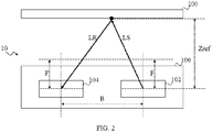
- FIG. 2 is a schematic diagram showing the 3D image sensing system 10 of FIG. 1 operating under an exemplary reference establishment operation; for the sake of brevity, the processor 110 is not shown in the drawing. Also, in FIG. 2 , The value of the baseline distance B between the light-emitting module 102 and the light sensing module 104 is known, and the value of the focal length F of the light-emitting module 102 is also known. The values of the baseline distance B and the focal length F may be pre-stored in the 3D image sensor 100 or a memory device (not shown) of the 3D image sensing system 10.
- FIG. 4A is a schematic diagram showing the known distance image 400 established under the operation shown in FIG. 2 .
- the reference object 200 is disposed at a location with a known distance Zref with respect to the 3D image sensor 100.
- the known distance Zref can be considered as the distance between the reference object 200 and the light-emitting module 102, as well as the distance between the reference object 200 and the light-sensing module 104.
- the surface of the reference object 200 facing the 3D image sensor 100 is substantially flat.
- the distances between the respective part of the reference object 200 and the 3D image sensor 100 are equal, that is to say, the depths are the same, i.e., all distances are the known distance Zref.
- the present application is not limited to such implementation.
- different portions on the surface of the reference object 200 may have different depths.
- the structured light LS emitted from the light-emitting module 102 can reach each and every portion on the surface of the reference object 200.
- the light-emitting module 102 emits structured light LS to the reference object 200, wherein the structured light LS has a known pattern.
- the structured light LS is point-structured light.
- the light-sensing module 104 receives the reflected structured light LR of the structured light LS that is reflected by the reference object 200.
- the reflected structured light LR also has a known pattern; that is, the structured light LR that is reflected by the reference object 200 and the emitted structured light LS have substantially the same structured light pattern.
- the processor 110 establishes a known distance image 400 based on the reflected structured light LR, see, FIG. 4A . Referring to FIG. 4A , the known pattern in the known distance image 400 is shown as the pattern P.
- FIG. 3 is a schematic diagram showing the 3D image sensing system 10 of FIG. 1 operating under an exemplary sensing operation.
- FIG. 4B is a schematic diagram showing the unknown distance image 450 established under the operation shown in FIG. 3 .
- the target 300 is disposed at a location with an unknown distance Zun with respect to the 3D image sensor 100.
- the surface of the target 300 facing the 3D image sensor 100 is substantially flat.
- the distances between the respective part of the target 300 and the 3D image sensor 100 are equal, that is to say, the depths are the same, i.e., all distances are the known distance Zun.
- the present application is not limited to such implementation.
- different portions on the surface of the target 300 may have different depths.
- the structured light LS emitted from the light-emitting module 102 can reach each and every portion on the surface of the target 300.
- the light-emitting module 102 emits structured light LS to the target 300.
- the light-sensing module 104 receives the reflected structured light LR of the structured light LS that is reflected by the target 300.
- the processor 110 measures the depth of the structured light and the depth of the ToF based on the emitted structured light LS and the reflected structured light LR.
- the processor 110 carries out the TOF distance measurement based on the ToFs of the structured light LS and the reflected structured light LR to obtain a corresponding first between the distance target 300 and the 3D image sensing system 10. In this way, the first distance can be obtained.
- the first distance has a global offset.
- a detected distance without the global offset is obtained, or a compensated detected distance.
- the compensated detected distance Z may still not be able to exactly equal the unknown distance Zun. Nonetheless, the elimination of the global offset alone already significantly improves the accuracy of the 3D image sensing system 10 in performing the TOF distance measurement.
- the calculation of the global compensation coefficient C is discussed below. Since measuring distances based on the triangulation principle is not affected by temperature, the thus-obtained distance does not have the global offset. In other words, the distance obtained through triangulation can be considered as the compensated detected distance Z. Therefore, by comparing the distance obtained through triangulation with the first distance Z TOF , it is feasible to estimate the global compensation coefficient C, the details of which are described below.
- Triangulation can be implemented using the structured light; during operation, the processor 100 establishes an unknown distance image 450 based on the reflected structured light LR, as shown in FIG. 4B .
- the known pattern in the unknown distance image 450 is shown as the pattern P'.
- the processor 100 estimates the disparity between the known distance image 400 and the unknown distance image 450 according to the known pattern. Specifically, the processor 100 estimates the disparity according to the relative relationship between the pattern P' of the unknown distance image 450 and the pattern P of the known distance image 400.
- the processor 100 can calculate a second distance based on the estimated disparity and the values of the known baseline distance B and the focal length F, followed by triangulation.
- the second distance is the distance obtained by performing triangulation on the structured light.
- the global compensation coefficient C can be obtained by substituting the term (Z) in Equation (1) with the second distance Z D calculated from Equation (2).
- the processor 100 calculate the second distance Z D based on disparity D, and then calculates the global compensation coefficient C based on the first distance Z TOF and the second distance Z D . Lastly, the processor 100 compensates the first distance Z TOF based on the thus-calculated global compensation coefficient C to eliminate the global offset. In other words, the compensated detected distance Z can be obtained by adding the calculated global compensation coefficient C to the first distance Z TOF as measured.
- the processor 100 estimates the disparity D performing vector geocoding upon the known distance image 400 and the unknown distance image 450.
- the known distance image 400 and the unknown distance image 450 are vector geocoded according to a single axis, e.g., coordinate axis (X+, X-).
- the present application is not limited to such implementation.
- the known distance image 400 and the unknown distance image 450 can be vector geocoded according to multiple axes.
- the coordinate point Xp in the pattern P of the known distance image 400 is known; for example, the coordinate point Xp can be 30, and is labeled as Xp(30) in FIG. 4A .
- the coordinate point Xp' in the pattern P' of the unknown distance image 450 is known; for example, the coordinate point Xp' is 60, and is labeled as Xp'(60) in FIG. 4B .
- the difference in the values of the coordinate points Xp and Xp' is the disparity D. in the present example, the disparity D is 30.
- the global compensation coefficient C can be obtained using Equation (1) and (2).
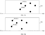
- FIG. 5A is a schematic diagram showing the known distance image 500 established under the operation shown in FIG. 2 .
- FIG. 5B is a schematic diagram showing the unknown distance image 550 established under the operation shown in FIG. 3 .
- the structured light is the plane-structured light, and the plane-structured light is speckle light.
- the structured light includes a plurality of known patterns.
- the methods for establishing the known distance image 500 and unknown distance image 550 are similar to those for establishing the known distance image 400 and the unknown distance image 450 shown in FIG. 4A and FIG. 4B , and hence are omitted herein for the sake of brevity.
- the known distance image 500 includes a plurality of patterns, such as patterns P1 and P2.
- the unknown distance image 550 includes a plurality of patterns, such as patterns P1' and P2', which respectively correspond to the plurality of patterns in the known distance image 500.
- the structured light is the plane-structured light
- the following embodiments can be used to calculate the global compensation coefficient C.
- pattern P1 of the known distance image 500 is used as an example, and the operation on the other patterns is the same.
- the value of the difference between the coordinate points of the patterns P1 and P1' is the disparity D corresponding to patterns P1 and P1'.
- the global compensation coefficient C is calculated based on Equation (1) and Equation (2).
- the number of the paired patterns is more than one.
- Each pair of patterns has its own first distance Z TOF and disparity D, and when the number of the paired patterns is greater than one, it is difficult to find a matching global compensation coefficient C using mathematic calculation, so that the global compensation coefficient C can be used to obtain a second distance Z D that is equal to the compensated detected distance Z for each pair of patterns. Therefore, in the present embodiment, the following Equation (3) is used to calculate the global compensation coefficient C.
- the thus-obtained global compensation coefficient C can be used to obtain a second distance Z D that is equal to the compensated detected distance Z for each pair of patterns.
- the known distance image 500 only includes patterns P1 and P2 (i.e., the total number of the patterns is 2)
- the unknown distance image 550 only includes patterns P1' and P2' (i.e., the total number of the patterns is 2).
- the pattern P1 is related to the distance Z TOF1 , and the disparity between the pattern P1 and pattern P1' is D1.
- the pattern P2 is related to the distance Z TOF2 , and the disparity between the pattern P2 and the pattern P2' is D2.
- Equation (3) can be further approximated to the following Equation (4).
- Equation (4) since the disparity D is part of the numerator, when all the disparity values D are added, it is easy to calculate. When this equivalent is reflected in the operation, it means that as long as the coordinates of all patterns of the known distance image 500 are summed and then the sum of the coordinates of all patterns of the unknown distance image 550 is subtracted, the global compensation coefficient C can be calculated. It is no longer necessary to perform an identification operation to find the paired patterns between the known distance image 500 and the unknown distance image 550.
- the coordinates of the patterns P1 and P2 are X1 and X2, respectively; and the coordinates of the patterns P1' and P2' are X1' and X2', respectively.
- Equation (4) For the term ( ⁇ D) in the term ⁇ D b ⁇ f of Equation (4), assuming the pattern P1 corresponding pattern P1' and pattern P2corresponding pattern P2', then the term ( ⁇ D) can be expressed as the term [(X1-X1')+(X2-X2')]. If we use the operation shown in Embodiment II, then the term ( ⁇ D) can be expressed as the term [ (X1+X2)-(X1'+X2') ].
- the processor 100 generates a first overall coordinates (i.e., (Xl'+X2')) based on the overall pattern of the unknown distance image 550 and generates a second overall coordinates (i.e., (X1+X2)) based on the overall pattern of the known distance image 500, and then determines the disparity D according to the difference between the first overall coordinates and the second overall coordinates.
- a first overall coordinates i.e., (Xl'+X2'
- a second overall coordinates i.e., (X1+X2)
- the present application calculates the global compensation coefficient for TOF measurement through the actual measuring data by using the structured light, which can compensate the global offset of the TOF measurement caused by the environmental temperature change, and make the measurement more accurate.
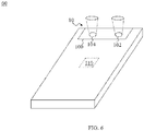
- FIG. 6 is a schematic block diagram of the 3D image sensing system 10 of FIG. 1 being applied in an electronic device 60 according to one embodiment of the present application.
- the electronic device 60 can be for example, a smart phone, personal digital assistant, hand-held computer system, tablet computer, or the like.
Landscapes
- Engineering & Computer Science (AREA)
- Physics & Mathematics (AREA)
- General Physics & Mathematics (AREA)
- Multimedia (AREA)
- Signal Processing (AREA)
- Radar, Positioning & Navigation (AREA)
- Computer Networks & Wireless Communication (AREA)
- Remote Sensing (AREA)
- Electromagnetism (AREA)
- Computer Vision & Pattern Recognition (AREA)
- Optics & Photonics (AREA)
- Theoretical Computer Science (AREA)
- Measurement Of Optical Distance (AREA)
- Length Measuring Devices By Optical Means (AREA)
Applications Claiming Priority (1)
| Application Number | Priority Date | Filing Date | Title |
|---|---|---|---|
| PCT/CN2019/123735 WO2021109138A1 (zh) | 2019-12-06 | 2019-12-06 | 三维图像传感系统以及相关电子装置以及飞时测距方法 |
Publications (2)
| Publication Number | Publication Date |
|---|---|
| EP3859395A1 true EP3859395A1 (de) | 2021-08-04 |
| EP3859395A4 EP3859395A4 (de) | 2021-08-04 |
Family
ID=70400257
Family Applications (1)
| Application Number | Title | Priority Date | Filing Date |
|---|---|---|---|
| EP19929181.6A Pending EP3859395A4 (de) | 2019-12-06 | 2019-12-06 | System zur erfassung dreidimensionaler bilder und zugehörige elektronische vorrichtung und flugzeitabstandsmessungsverfahren |
Country Status (4)
| Country | Link |
|---|---|
| US (1) | US11095866B2 (de) |
| EP (1) | EP3859395A4 (de) |
| CN (1) | CN111095914B (de) |
| WO (1) | WO2021109138A1 (de) |
Families Citing this family (5)
| Publication number | Priority date | Publication date | Assignee | Title |
|---|---|---|---|---|
| CN111432144B (zh) * | 2020-06-12 | 2021-06-18 | 深圳市汇顶科技股份有限公司 | 成像系统以及相关电子装置及成像系统的操作方法 |
| WO2021248427A1 (zh) | 2020-06-12 | 2021-12-16 | 深圳市汇顶科技股份有限公司 | 深度传感装置以及相关电子装置及深度传感装置的操作方法 |
| CN111443361B (zh) * | 2020-06-18 | 2022-03-29 | 深圳市汇顶科技股份有限公司 | 飞时测距方法与相关系统 |
| JP2022163641A (ja) * | 2021-04-14 | 2022-10-26 | 富士フイルムビジネスイノベーション株式会社 | 発光装置及び計測装置 |
| EP4215937A1 (de) * | 2022-01-25 | 2023-07-26 | Baden-Württemberg Stiftung gGmbH | Vorrichtung und verfahren zur bestimmung einer distanz zu einem objekt |
Family Cites Families (11)
| Publication number | Priority date | Publication date | Assignee | Title |
|---|---|---|---|---|
| EP1576385A2 (de) * | 2002-11-26 | 2005-09-21 | James F. Munro | Vorrichtung zur präzisen distanz- und geschwindigkeitsmessungund verfahren dafür |
| US8760631B2 (en) | 2010-01-27 | 2014-06-24 | Intersil Americas Inc. | Distance sensing by IQ domain differentiation of time of flight (TOF) measurements |
| JP2014077668A (ja) * | 2012-10-09 | 2014-05-01 | Optex Co Ltd | 寸法計測装置および寸法計測方法 |
| US8796637B1 (en) | 2013-05-24 | 2014-08-05 | Kabushiki Kaisha Toshiba | Timing calibration for time-of-flight (TOF) PET using positron-emitting isotopes and annihilation targets |
| US9823352B2 (en) * | 2014-10-31 | 2017-11-21 | Rockwell Automation Safety Ag | Absolute distance measurement for time-of-flight sensors |
| CN109242901B (zh) * | 2017-07-11 | 2021-10-22 | 深圳市道通智能航空技术股份有限公司 | 应用于三维相机的图像校准方法和装置 |
| CN107657635B (zh) * | 2017-10-17 | 2022-03-29 | 奥比中光科技集团股份有限公司 | 深度相机温度误差校正方法及系统 |
| US11099009B2 (en) * | 2018-03-29 | 2021-08-24 | Sony Semiconductor Solutions Corporation | Imaging apparatus and imaging method |
| US10663567B2 (en) * | 2018-05-04 | 2020-05-26 | Microsoft Technology Licensing, Llc | Field calibration of a structured light range-sensor |
| CN108711167A (zh) * | 2018-05-15 | 2018-10-26 | 深圳奥比中光科技有限公司 | 深度成像系统及其温度误差校正方法 |
| CN108917639A (zh) * | 2018-05-15 | 2018-11-30 | 深圳奥比中光科技有限公司 | 深度成像系统及其温度误差校正方法 |
-
2019
- 2019-12-06 WO PCT/CN2019/123735 patent/WO2021109138A1/zh unknown
- 2019-12-06 CN CN201980004362.9A patent/CN111095914B/zh active Active
- 2019-12-06 EP EP19929181.6A patent/EP3859395A4/de active Pending
-
2020
- 2020-11-18 US US16/951,628 patent/US11095866B2/en active Active
Also Published As
| Publication number | Publication date |
|---|---|
| WO2021109138A1 (zh) | 2021-06-10 |
| US11095866B2 (en) | 2021-08-17 |
| CN111095914A (zh) | 2020-05-01 |
| US20210176445A1 (en) | 2021-06-10 |
| EP3859395A4 (de) | 2021-08-04 |
| CN111095914B (zh) | 2022-04-29 |
Similar Documents
| Publication | Publication Date | Title |
|---|---|---|
| EP3859395A1 (de) | System zur erfassung dreidimensionaler bilder und zugehörige elektronische vorrichtung und flugzeitabstandsmessungsverfahren | |
| CN109729721B (zh) | 光学测距方法以及光学测距装置 | |
| US9659378B2 (en) | Point cloud position data processing device, point cloud position data processing system, point cloud position data processing method, and program therefor | |
| JP4650751B2 (ja) | 三次元形状データの位置合わせ方法と装置 | |
| US9317735B2 (en) | Information processing apparatus, information processing method, and program to calculate position and posture of an object having a three-dimensional shape | |
| US8971576B2 (en) | Information processing apparatus and processing method thereof | |
| JP6782903B2 (ja) | 自己運動推定システム、自己運動推定システムの制御方法及びプログラム | |
| EP3716210B1 (de) | Verfahren und vorrichtung zur erzeugung dreidimensionaler punktgruppendaten, positionsschätzungsverfahren, vorrichtung zur erzeugung dreidimensionaler punktgruppendaten und positionsschätzungsvorrichtung | |
| JP2008286582A (ja) | レーダ信号処理装置及びレーダ信号処理方法 | |
| Zhou | A closed-form algorithm for the least-squares trilateration problem | |
| CN113111513B (zh) | 传感器配置方案确定方法、装置、计算机设备及存储介质 | |
| KR20120065067A (ko) | 다중센서 융합을 통한 3차원 환경 모델링 장치 및 그 방법 | |
| EP3333829B1 (de) | Schrittdetektionsvorrichtung und schrittdetektionsverfahren | |
| US20170108338A1 (en) | Method for geolocating a carrier based on its environment | |
| JP2017004228A (ja) | 軌跡推定方法、軌跡推定装置及び軌跡推定プログラム | |
| CN114266871B (zh) | 机器人、地图质量评估方法和存储介质 | |
| US11914062B2 (en) | Technique for calibrating a positioning system | |
| García-Moreno et al. | Error propagation and uncertainty analysis between 3D laser scanner and camera | |
| EP4050377A1 (de) | System zur erfassung dreidimensionaler bilder und zugehörige elektronische vorrichtung und flugzeitabstandsmessungsverfahren | |
| US10694459B2 (en) | Positioning access points selection | |
| KR20170051752A (ko) | Tof 카메라 제어방법 | |
| JP2024501731A (ja) | 複数カメラによる速度測定方法及び速度測定装置 | |
| CN114565683A (zh) | 一种精度确定方法、装置、设备、介质及产品 | |
| US20240114119A1 (en) | Image processing device, image processing method, and program | |
| JPWO2018212284A1 (ja) | 測定装置、測定方法およびプログラム |
Legal Events
| Date | Code | Title | Description |
|---|---|---|---|
| STAA | Information on the status of an ep patent application or granted ep patent |
Free format text: STATUS: UNKNOWN |
|
| STAA | Information on the status of an ep patent application or granted ep patent |
Free format text: STATUS: THE INTERNATIONAL PUBLICATION HAS BEEN MADE |
|
| PUAI | Public reference made under article 153(3) epc to a published international application that has entered the european phase |
Free format text: ORIGINAL CODE: 0009012 |
|
| STAA | Information on the status of an ep patent application or granted ep patent |
Free format text: STATUS: REQUEST FOR EXAMINATION WAS MADE |
|
| 17P | Request for examination filed |
Effective date: 20201124 |
|
| A4 | Supplementary search report drawn up and despatched |
Effective date: 20210701 |
|
| AK | Designated contracting states |
Kind code of ref document: A1 Designated state(s): AL AT BE BG CH CY CZ DE DK EE ES FI FR GB GR HR HU IE IS IT LI LT LU LV MC MK MT NL NO PL PT RO RS SE SI SK SM TR |
|
| DAV | Request for validation of the european patent (deleted) | ||
| DAX | Request for extension of the european patent (deleted) | ||
| STAA | Information on the status of an ep patent application or granted ep patent |
Free format text: STATUS: EXAMINATION IS IN PROGRESS |
|
| 17Q | First examination report despatched |
Effective date: 20230728 |