EP3858308A1 - Individually packaged absorbent article - Google Patents
Individually packaged absorbent article Download PDFInfo
- Publication number
- EP3858308A1 EP3858308A1 EP19864268.8A EP19864268A EP3858308A1 EP 3858308 A1 EP3858308 A1 EP 3858308A1 EP 19864268 A EP19864268 A EP 19864268A EP 3858308 A1 EP3858308 A1 EP 3858308A1
- Authority
- EP
- European Patent Office
- Prior art keywords
- absorbent article
- hip
- sheet
- flaps
- widthwise
- Prior art date
- Legal status (The legal status is an assumption and is not a legal conclusion. Google has not performed a legal analysis and makes no representation as to the accuracy of the status listed.)
- Granted
Links
Images





Classifications
-
- A—HUMAN NECESSITIES
- A61—MEDICAL OR VETERINARY SCIENCE; HYGIENE
- A61F—FILTERS IMPLANTABLE INTO BLOOD VESSELS; PROSTHESES; DEVICES PROVIDING PATENCY TO, OR PREVENTING COLLAPSING OF, TUBULAR STRUCTURES OF THE BODY, e.g. STENTS; ORTHOPAEDIC, NURSING OR CONTRACEPTIVE DEVICES; FOMENTATION; TREATMENT OR PROTECTION OF EYES OR EARS; BANDAGES, DRESSINGS OR ABSORBENT PADS; FIRST-AID KITS
- A61F13/00—Bandages or dressings; Absorbent pads
- A61F13/15—Absorbent pads, e.g. sanitary towels, swabs or tampons for external or internal application to the body; Supporting or fastening means therefor; Tampon applicators
- A61F13/45—Absorbent pads, e.g. sanitary towels, swabs or tampons for external or internal application to the body; Supporting or fastening means therefor; Tampon applicators characterised by the shape
- A61F13/47—Sanitary towels, incontinence pads or napkins
- A61F13/4704—Sanitary towels, incontinence pads or napkins having preferential bending zones, e.g. fold lines or grooves
-
- A—HUMAN NECESSITIES
- A61—MEDICAL OR VETERINARY SCIENCE; HYGIENE
- A61F—FILTERS IMPLANTABLE INTO BLOOD VESSELS; PROSTHESES; DEVICES PROVIDING PATENCY TO, OR PREVENTING COLLAPSING OF, TUBULAR STRUCTURES OF THE BODY, e.g. STENTS; ORTHOPAEDIC, NURSING OR CONTRACEPTIVE DEVICES; FOMENTATION; TREATMENT OR PROTECTION OF EYES OR EARS; BANDAGES, DRESSINGS OR ABSORBENT PADS; FIRST-AID KITS
- A61F13/00—Bandages or dressings; Absorbent pads
- A61F13/15—Absorbent pads, e.g. sanitary towels, swabs or tampons for external or internal application to the body; Supporting or fastening means therefor; Tampon applicators
-
- A—HUMAN NECESSITIES
- A61—MEDICAL OR VETERINARY SCIENCE; HYGIENE
- A61F—FILTERS IMPLANTABLE INTO BLOOD VESSELS; PROSTHESES; DEVICES PROVIDING PATENCY TO, OR PREVENTING COLLAPSING OF, TUBULAR STRUCTURES OF THE BODY, e.g. STENTS; ORTHOPAEDIC, NURSING OR CONTRACEPTIVE DEVICES; FOMENTATION; TREATMENT OR PROTECTION OF EYES OR EARS; BANDAGES, DRESSINGS OR ABSORBENT PADS; FIRST-AID KITS
- A61F13/00—Bandages or dressings; Absorbent pads
- A61F13/15—Absorbent pads, e.g. sanitary towels, swabs or tampons for external or internal application to the body; Supporting or fastening means therefor; Tampon applicators
- A61F13/15577—Apparatus or processes for manufacturing
- A61F13/15707—Mechanical treatment, e.g. notching, twisting, compressing, shaping
- A61F13/15747—Folding; Pleating; Coiling; Stacking; Packaging
-
- A—HUMAN NECESSITIES
- A61—MEDICAL OR VETERINARY SCIENCE; HYGIENE
- A61F—FILTERS IMPLANTABLE INTO BLOOD VESSELS; PROSTHESES; DEVICES PROVIDING PATENCY TO, OR PREVENTING COLLAPSING OF, TUBULAR STRUCTURES OF THE BODY, e.g. STENTS; ORTHOPAEDIC, NURSING OR CONTRACEPTIVE DEVICES; FOMENTATION; TREATMENT OR PROTECTION OF EYES OR EARS; BANDAGES, DRESSINGS OR ABSORBENT PADS; FIRST-AID KITS
- A61F13/00—Bandages or dressings; Absorbent pads
- A61F13/15—Absorbent pads, e.g. sanitary towels, swabs or tampons for external or internal application to the body; Supporting or fastening means therefor; Tampon applicators
- A61F13/45—Absorbent pads, e.g. sanitary towels, swabs or tampons for external or internal application to the body; Supporting or fastening means therefor; Tampon applicators characterised by the shape
- A61F13/47—Sanitary towels, incontinence pads or napkins
- A61F13/472—Sanitary towels, incontinence pads or napkins specially adapted for female use
-
- A—HUMAN NECESSITIES
- A61—MEDICAL OR VETERINARY SCIENCE; HYGIENE
- A61F—FILTERS IMPLANTABLE INTO BLOOD VESSELS; PROSTHESES; DEVICES PROVIDING PATENCY TO, OR PREVENTING COLLAPSING OF, TUBULAR STRUCTURES OF THE BODY, e.g. STENTS; ORTHOPAEDIC, NURSING OR CONTRACEPTIVE DEVICES; FOMENTATION; TREATMENT OR PROTECTION OF EYES OR EARS; BANDAGES, DRESSINGS OR ABSORBENT PADS; FIRST-AID KITS
- A61F13/00—Bandages or dressings; Absorbent pads
- A61F13/15—Absorbent pads, e.g. sanitary towels, swabs or tampons for external or internal application to the body; Supporting or fastening means therefor; Tampon applicators
- A61F13/45—Absorbent pads, e.g. sanitary towels, swabs or tampons for external or internal application to the body; Supporting or fastening means therefor; Tampon applicators characterised by the shape
- A61F13/47—Sanitary towels, incontinence pads or napkins
- A61F13/475—Sanitary towels, incontinence pads or napkins characterised by edge leakage prevention means
- A61F13/4751—Sanitary towels, incontinence pads or napkins characterised by edge leakage prevention means the means preventing fluid flow in a transversal direction
- A61F13/4756—Sanitary towels, incontinence pads or napkins characterised by edge leakage prevention means the means preventing fluid flow in a transversal direction the means consisting of grooves, e.g. channels, depressions or embossments, resulting in a heterogeneous surface level
-
- A—HUMAN NECESSITIES
- A61—MEDICAL OR VETERINARY SCIENCE; HYGIENE
- A61F—FILTERS IMPLANTABLE INTO BLOOD VESSELS; PROSTHESES; DEVICES PROVIDING PATENCY TO, OR PREVENTING COLLAPSING OF, TUBULAR STRUCTURES OF THE BODY, e.g. STENTS; ORTHOPAEDIC, NURSING OR CONTRACEPTIVE DEVICES; FOMENTATION; TREATMENT OR PROTECTION OF EYES OR EARS; BANDAGES, DRESSINGS OR ABSORBENT PADS; FIRST-AID KITS
- A61F13/00—Bandages or dressings; Absorbent pads
- A61F13/15—Absorbent pads, e.g. sanitary towels, swabs or tampons for external or internal application to the body; Supporting or fastening means therefor; Tampon applicators
- A61F13/51—Absorbent pads, e.g. sanitary towels, swabs or tampons for external or internal application to the body; Supporting or fastening means therefor; Tampon applicators characterised by the outer layers of the pads
- A61F13/514—Backsheet, i.e. the impermeable cover or layer furthest from the skin
- A61F13/51456—Backsheet, i.e. the impermeable cover or layer furthest from the skin characterised by its properties
-
- A—HUMAN NECESSITIES
- A61—MEDICAL OR VETERINARY SCIENCE; HYGIENE
- A61F—FILTERS IMPLANTABLE INTO BLOOD VESSELS; PROSTHESES; DEVICES PROVIDING PATENCY TO, OR PREVENTING COLLAPSING OF, TUBULAR STRUCTURES OF THE BODY, e.g. STENTS; ORTHOPAEDIC, NURSING OR CONTRACEPTIVE DEVICES; FOMENTATION; TREATMENT OR PROTECTION OF EYES OR EARS; BANDAGES, DRESSINGS OR ABSORBENT PADS; FIRST-AID KITS
- A61F13/00—Bandages or dressings; Absorbent pads
- A61F13/15—Absorbent pads, e.g. sanitary towels, swabs or tampons for external or internal application to the body; Supporting or fastening means therefor; Tampon applicators
- A61F13/551—Packaging before or after use
- A61F13/5513—Packaging before or after use packaging of feminine sanitary napkins
- A61F13/55135—Packaging before or after use packaging of feminine sanitary napkins before use
- A61F13/5514—Packaging before or after use packaging of feminine sanitary napkins before use each item packaged single
-
- A—HUMAN NECESSITIES
- A61—MEDICAL OR VETERINARY SCIENCE; HYGIENE
- A61F—FILTERS IMPLANTABLE INTO BLOOD VESSELS; PROSTHESES; DEVICES PROVIDING PATENCY TO, OR PREVENTING COLLAPSING OF, TUBULAR STRUCTURES OF THE BODY, e.g. STENTS; ORTHOPAEDIC, NURSING OR CONTRACEPTIVE DEVICES; FOMENTATION; TREATMENT OR PROTECTION OF EYES OR EARS; BANDAGES, DRESSINGS OR ABSORBENT PADS; FIRST-AID KITS
- A61F13/00—Bandages or dressings; Absorbent pads
- A61F13/15—Absorbent pads, e.g. sanitary towels, swabs or tampons for external or internal application to the body; Supporting or fastening means therefor; Tampon applicators
- A61F13/56—Supporting or fastening means
- A61F13/5605—Supporting or fastening means specially adapted for sanitary napkins or the like
- A61F13/5616—Supporting or fastening means specially adapted for sanitary napkins or the like using flaps, e.g. adhesive, for attachment to the undergarment
-
- A—HUMAN NECESSITIES
- A61—MEDICAL OR VETERINARY SCIENCE; HYGIENE
- A61F—FILTERS IMPLANTABLE INTO BLOOD VESSELS; PROSTHESES; DEVICES PROVIDING PATENCY TO, OR PREVENTING COLLAPSING OF, TUBULAR STRUCTURES OF THE BODY, e.g. STENTS; ORTHOPAEDIC, NURSING OR CONTRACEPTIVE DEVICES; FOMENTATION; TREATMENT OR PROTECTION OF EYES OR EARS; BANDAGES, DRESSINGS OR ABSORBENT PADS; FIRST-AID KITS
- A61F13/00—Bandages or dressings; Absorbent pads
- A61F13/15—Absorbent pads, e.g. sanitary towels, swabs or tampons for external or internal application to the body; Supporting or fastening means therefor; Tampon applicators
- A61F2013/16—Sanitary towels; Means for supporting or fastening them
-
- A—HUMAN NECESSITIES
- A61—MEDICAL OR VETERINARY SCIENCE; HYGIENE
- A61F—FILTERS IMPLANTABLE INTO BLOOD VESSELS; PROSTHESES; DEVICES PROVIDING PATENCY TO, OR PREVENTING COLLAPSING OF, TUBULAR STRUCTURES OF THE BODY, e.g. STENTS; ORTHOPAEDIC, NURSING OR CONTRACEPTIVE DEVICES; FOMENTATION; TREATMENT OR PROTECTION OF EYES OR EARS; BANDAGES, DRESSINGS OR ABSORBENT PADS; FIRST-AID KITS
- A61F13/00—Bandages or dressings; Absorbent pads
- A61F13/15—Absorbent pads, e.g. sanitary towels, swabs or tampons for external or internal application to the body; Supporting or fastening means therefor; Tampon applicators
- A61F13/45—Absorbent pads, e.g. sanitary towels, swabs or tampons for external or internal application to the body; Supporting or fastening means therefor; Tampon applicators characterised by the shape
- A61F13/47—Sanitary towels, incontinence pads or napkins
- A61F2013/4706—Sanitary towels, incontinence pads or napkins enlarged in the anal area
Definitions
- the present invention relates to an individually wrapped absorbent article.
- absorbent articles such as sanitary napkins, panty liners, incontinence pads, and the like
- an absorbent is sandwiched between a liquid-permeable top sheet and a liquid-impermeable back sheet.
- Some of these absorbent articles are adapted for prolonged use or for short periods of time when large volumes of body fluid are discharged, with a main body of an absorbent article extending in a rear area and with flaps projecting from both sides of the rear side thereby extending the rear area.
- Absorbent articles are typically provided as an individual wrapped article wrapped with a wrapping sheet.
- the flaps protruding from both sides are folded toward the main body of the absorbent article, and then tri-folded or quad-folded in the lengthwise direction and wrapped (for example, FIG. 4 in Patent Document 1).
- Patent Document 1 Japanese Patent Application Laid-Open No. 2003-339764
- one aspect of the invention is to provide an absorbent article that is compactly wrapped by reducing a spread of flaps in a widthwise direction upon folding.
- an individually wrapped absorbent article includes an absorbent article having a main body, the main body including a liquid-impermeable back sheet, an absorbent, and a liquid-permeable top sheet that are laminated in aforementioned order, the main body is the absorbent article having a predetermined length in a lengthwise direction and a predetermined width in a direction perpendicular to the lengthwise direction; and a wrapping sheet that wraps the absorbent article individually, wherein the absorbent article includes a middle area that includes a portion corresponding to a body fluid excretion orifice of a wearer upon wearing the absorbent article, and a rear area that is adjacently behind the middle area and extends to a rear end of the absorbent article, wherein the absorbent article includes hip-hold flaps projecting laterally from the main body in the rear area, and an outline of the hip-hold flaps has convex portions with a radius of curvature of 5 to 500 mm, wherein anti-slipping portions are disposed on a back surface of
- the invention is capable of providing an absorbent article that is compactly wrapped by reducing a spread of flaps in a widthwise direction upon folding.
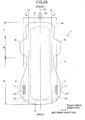
- FIG. 2A illustrates a partially cutaway plan view of absorbent article 1 in one embodiment of the invention of the present invention.
- FIG. 2B illustrates a cross-sectional view of line I-I of absorbent article 1.
- the absorbent article 1 includes a main body (absorbent article body) 8 having a liquid-impermeable back sheet 2, a liquid-permeable top sheet 3, and an absorbent 4 provided between the top sheet 3 and the back sheet 2.
- the top sheet 3 contacts skin (skin side or top side), and the back sheet 2 is fixed to an underwear (underwear side or back side).
- Both sides of the top sheet 3 of the absorbent article 1 may be provided with side non-woven fabrics 7 and 7 extending in a lengthwise direction so as to overlap with both edges of the widthwise direction of the absorbent 4 in a plan view.
- a main body 8 has a predetermined length in a lengthwise direction, a predetermined width in a widthwise direction perpendicular to the lengthwise direction, and an overall elongated shape in the lengthwise direction.
- the width of the main body 8 is substantially constant in the illustrated example but may vary across the lengthwise direction.
- the absorbent article 1 can have a generally symmetrical shape with respect to the centerline (centerline in lengthwise direction) CL extending in a lengthwise direction.
- the configuration of the absorbent article 1 (including the thickness and density of the absorbent 4) may be substantially symmetrical with the centerline as the axis of symmetry or may be asymmetric.
- the length in the lengthwise direction (overall length of the main body 8) of absorbent article 1 is not particularly limited but preferably 250 to 450 mm, and more preferably from 270 to 380 mm.
- the length of the widthwise direction of the main body 8 (the width of the absorbent 4) is not particularly limited but is preferably 50 to 200 mm, and is more preferably 70 to 120 mm.
- the absorbent article 1 has a portion A corresponding to a body fluid excretion orifice corresponding to a body fluid excretion orifice such as a vaginal opening of a wearer when the absorbent article is worn.
- the portion A corresponding to a body fluid excretion orifice has a center Ac.
- the center Ac is positioned on the centerline CL in the lengthwise direction and is positioned on the center of the lengthwise direction of the portion A corresponding to a body fluid excretion orifice.
- the position of the center Ac is 70 to 130 mm away from the front end of the absorbent article 1.
- the portion A corresponding to a body fluid excretion orifice may have a length (length in the lengthwise direction) of 10 to 50 mm and preferably 20 to 40 mm.
- the portion A corresponding to a body fluid excretion orifice may have a width (length in the widthwise direction) of 5 to 40 mm and preferably 10 mm to 30 mm. It should be noted that the shape and size of the portion A corresponding to a body fluid excretion orifice illustrated in the drawings are merely examples for ease of explanation.
- the absorbent article 1 has a middle area M including a portion corresponding to a body fluid excretion orifice A described above, a front area F in front of the middle area M, and a rear area R in behind of the middle area M.
- the middle area M corresponds approximately to the wearer's crotch when worn
- the rear area R corresponds approximately to the wearer's buttocks when worn.
- the middle area M may have wing-like flaps W and W extending from both sides thereof to securely fix the absorbent article 1 to an underwear upon mounting.
- the front area F is the area from the front origins or the near the front origins of the wing-like flaps W and W to the front end of the absorbent article.
- the rear area R is the area from the rear origins or near the rear origins of the wing-like flaps W and W to the rear end of the absorbent article.
- the absorbent article 1 has wing-like flaps W and W. However, the absorbent article 1 need not have wing-like flaps W and W.
- the area from the front origins or near the front origins of the wing-like flaps W and W to the front end of the absorbent article is determined as the front area F.
- the area from the rear origins or near the rear origins of the wing-like flaps W and W to the rear end of the absorbent article is determined as the rear area R.
- the back sheet 2 may be a sheet material having at least a water shielding property, such as an olefin-based resin sheet such as polyethylene or polypropylene.
- a laminated non-woven fabric made by laminating a non-woven material with a polyethylene sheet or the like or a non-woven sheet made to be substantially liquid-impermeable by interposing a waterproof film with the laminated material or the like can be used.
- a microporous sheet or the like may be obtained by melt-kneading an inorganic filler into an olefinic-based resin such as polyethylene or polypropylene to form a sheet, followed by stretching the sheet in a monoaxial or a biaxial direction.
- the top sheet 3 is a liquid-permeable sheet through which bodily fluids such as menstrual blood, discharge, and urine pass.
- a porous or non-porous non-woven fabric or a porous plastic sheet is preferably used.
- the material fibers constituting the non-woven fabric for example, olefins such as polyethylene, polypropylene, and the like; synthetic fibers such as polyester, polyamide, and the like; regenerated fibers such as rayon, cupra, and the like; and blended fibers, as well as natural fibers such as cotton and the like can be used alone or in combination.
- non-woven fabric processing methods include a span lace method, a spunbond method, a thermal bond method, a melt-blown method, a needle punch method, and the like.
- the span lace method is preferably used from the view point of flexibility
- the spunbond method is preferably used from the view point of producing a non-woven fabric with high drape properties
- the thermal bond method is preferably used from the view point of producing a non-woven fabric that is bulky and soft.
- composite fibers such as core-sheath type fibers with high melting point fibers as the core and low melting point fibers as the sheath, side-by-side type fibers, split type fibers, and the like may be used.
- the materials of absorbent 4 are not particularly limited as long as the materials are capable of absorbing and retaining body fluid.
- Cotton pulps and water absorbent polymers are preferably contained in the materials.
- the water absorbent polymers include superabsorbent polymer (SAP), superabsorbent polymer fiber (SAF), and a combination thereof.
- the pulps include cellulosic fibers such as chemical pulps obtained from woods, dissolved pulps, and the like; and artificial cellulose fibers such as rayon, acetate, and the like.
- Examples of raw materials for chemical pulps include hardwood, coniferous wood, and the like. Coniferous wood is preferably used because of its long fiber length.
- Synthetic fibers may also be mixed with the absorbent 4.
- the synthetic fibers include polyolefins such as polyethylene, polypropylene, and the like; polyesters such as polyethylene terephthalate, polybutylene terephthalate, and the like; polyamides such as nylon and the like; and copolymers thereof.
- two kinds of the synthetic fibers may be used in combination.
- composite fibers such as core-sheath type fibers with high melting point fibers as the core and low melting point fibers as the sheath, side-by-side type fibers, split type fibers, and the like may be used.
- hydrophobic fibers may be surface-treated with a hydrophilic agent to confer affinity to body fluids.
- the absorbent 4 is preferably manufactured by laminating fibers or an air laid process.
- the thickness of the absorbent 4 is in the range of 0.3 to 30 mm and preferably in the range of 1.0 to 15 mm.
- the absorbent 4 as a whole need not have a uniform thickness across the entire surface, and the area of the portion A corresponding to a body fluid excretion orifice and its proximity may be inflated.
- the absorbent 4 may be wrapped with a wrapped sheet formed from crepe paper or non-woven fabric to maintain its shape or the like.
- the absorbent 4 can be prevented from becoming warped or cracked by surrounding the absorbent with a packaging a packaging sheet.
- a packaging sheet a colorless (that is white) crepe paper or a non-woven material may be used, or a colored packaging sheet may be used.
- the color of the packaging sheet can also be reflected as a light color from the top sheet 3. Therefore, the color of the excreted body fluid can be close to the reflected color of the packaging sheet 9 to make it inconspicuous.
- the packaging sheet can be colored, for example, as a complementary color of body fluids.
- the packaging sheet can be colored green, which is the complementary color of red.
- the side non-woven fabric 7 may be formed from non-woven fabric materials that are subjected to an appropriate water-repellent treatment or hydrophilic treatment in accordance with the purpose of preventing the body fluid from penetrating or enhancing the feel against the skin.
- the non-woven materials may be, for example, natural fibers, synthetic fibers, regenerated fibers, and the like.
- a water-repellent agent such as a silicon-based material or a paraffin-based material, may be used.
- the outer edges of the back sheet 2 and the top sheet 3 are bonded by an adhesive method such as hot melt, heat seal, ultrasonic seal, or the like.
- the side non-woven fabrics 7 and 7 extending from the side of the main body 8 and the back sheet 2 are bonded by at least one of the adhesive methods.
- the wing-like flaps W and W described above can be formed in the middle area M
- the hip-hold flaps HF and HF described below can be formed in the rear area R.
- the main body 8 may be provided with pressure grooves.
- the pressure grooves are grooves (also referred to as fitting embosses) that are obtained by laminating the top sheet 3 and the absorbent 4 and then pressurizing both of them together such that the top sheet 3 side is depressed toward the sheet 2.
- the pressure grooves can be formed by laminating the top sheet 3 onto the absorbent 4 and passing the resulting laminate between a pair of pressurizing rolls. For example, a convex roll on the side of the top sheet 3 of the laminate and a flat roll on the side of the absorbent 4 can be arranged and pressurized by both rolls.
- the absorbent article 1 in the present embodiment is the rear area R expanded in the lengthwise direction and the widthwise direction. More specifically, the main body 8 extends in the lengthwise direction, and the hip-hold flaps HF and HF extend on both sides of the body 8.
- the flexibility of the hip-hold flaps HF and HF allows them to be applied along round portion of the buttocks, and also causes them to readily conform to the movements of the buttocks.
- the hip-hold flaps HF and HF are formed by bonding the side non-woven fabrics 7 and 7 and the back sheet 2, and do not include absorbent.
- the hip-hold flaps HF and HF may contain a thin absorbent as long as the absorbent can have flexibility to align with the round portions of the buttocks.
- the absorbent article 1 in the present embodiment has an extended rear area R. This effectively prevents leakage of body fluid in the rear area R. Accordingly, the absorbent article 1 can be suitably used as a sanitary napkin for long-time or night-time use, because it can accommodate a situation where long hours of use is expected or a situation where a large amount of body fluid is excreted within a short period of time.
- the outline of the hip-hold flaps HF has convex portions 11 which are curved. That is, each convex portion 11 may have a convex-shaped outline with a center of curvature on the hip-hold flaps HF or the main body 8 in a planar view.
- the radius of curvature at apexes 11P of the convex portions 11 may be 5 to 500 mm and preferably 35 to 200 mm.
- the hip-hold flaps HF have an external shape having a convex portion having a predetermined radius of curvature, so that the flat hip-hold flaps HF readily deform to match the curved surface of buttocks.
- the hip-hold flaps HF are easily moved from both ends of the convex portions. Therefore, the rear area R can be tightly attached to the curved surface of buttocks to improve the effectiveness of preventing leakage of body fluid in the rear area R. In addition, a feeling of discomfort when the edges of the hip-hold flaps HF and HF contact the skin can be reduced, because the contour is curved.
- each hip-hold flap HF is shaped to have one convex portion, but the convex portion of the hip-hold flap HF may be two or more. That is, the outline of the hip-hold flap HF may have irregularities. In such a case, each convex portion preferably has a radius of curvature in the range described above.
- the absorbent article 1 may have a maximum width at a position where the hip-hold flap HF has a convex portion 11 (where the convex portion is two or more, the convex portion has the most protruding portion outward in the width direction).
- This maximum width is preferably 70 to 200 mm and more preferably 100 to 160 mm.
- the position of the convex portion 11 is preferably in a range from the position of the rear area R in the center of the lengthwise direction to the rear direction. This allows the wide part of the hip-hold flaps HF and HF to be positioned near the point where the buttocks groove (gluteal cleft) begins to become shallow and the buttocks groove ends. This prevents leakage of fluid that has moved to the rear through the buttocks groove in the lateral direction.
- the hip-hold flaps HF and HF are capable of preventing the hip-hold flaps HF and HF from hitting around legs and causing a feeling of discomfort because the wide portion of the hip-hold flaps HF and HF can be moved away from the position where the pressure is easily applied from the legs.
- the absorbent article 1 in the present embodiment is provided with anti-slipping portions 9 on the sides of the back sheet 2 for securing the absorbent article 1 to underwear when worn.
- the anti-slipping portions 9 are preferably disposed on the back sheet 2 side of the main body 8, the wing-shaped flaps W and W, and the hip-hold flaps HF and HF.
- FIG. 2A illustrates the anti-slipping portions 9 disposed on the back sheet 2 side of the hip-hold flaps HF and the HF. The other anti-slipping portions are omitted.
- the materials used for the anti-slipping portions 9 are not particularly limited as long as the absorbent article 1 functions so as not to slip from the underwear.
- the anti-slipping portions 9 can be formed as an adhesive layer or non-adhesive layer.
- adhesive layers include a styrene-based polymer, a tackifier, a plasticizer, and a combination thereof.
- styrene-based polymer examples include a styrene-ethylene-butylene-styrene block copolymer, a styrene-butylene-styrene block copolymer, a styrene-isobutylene-styrene copolymer, a styrene-butadiene-styrene block copolymer, and the like.
- One or more types of styrene-butadiene-styrene block copolymers may be used.
- a styrene-butadiene-styrene block copolymer is preferably used from the view point of thermostability.
- a solid material may be used at room temperature.
- the tackifiers include C5-based petroleum resins, C9-based petroleum resins, dicyclopentadiene-based petroleum resins, rosin-based petroleum resins, polyterpene resins, terpenephenol resins, and the like.
- the plasticizers include monomer plasticizers such as trifrecyl phosphate, dibutyl phthalate, and dioctyl phthalate, as well as polymer plasticizers such as vinyl polymers, polyesters, and the like.
- the anti-slipping portions 9 may be provided along the lengthwise direction of the hip-hold flaps HF and HF. That is, the anti-slipping portions 9 may be provided along the lengthwise direction of the absorbent article 1. Accordingly, the anti-slipping portions 9 have an elongated shape in the lengthwise direction as illustrated in FIG. 2A .
- the length of the anti-slipping portions 9 may be from 10 to 100 mm and preferably from 15 to 50 mm.
- the width (length in widthwise direction) of the anti-slipping portions 9 may be from 0.3 to 20 mm and preferably from 0.5 to 15 mm.
- the anti-slipping portions 9 in the hip-hold flaps HF and HF may be provided as a contiguous single area or as a plurality of areas that are discontinuous in the lengthwise direction and/or the widthwise direction.
- the wrapping sheet 20 is not particularly limited in configuration and size as long as the wrapping sheet can wrap the absorbent article 1.
- the wrapping sheet 20 may be rectangular in plan view as described below ( FIG. 3A ).
- the wrapping sheet 20 may be a polyolefin-based film such as polypropylene, polyethylene, and the like; a film such as polyester, polyvinyl alcohol, and the like; a non-woven fabric; a laminated non-woven fabric (including a non-woven polylaminated fabric in which a polymeric layer is laminated on one or both surfaces of the non-woven fabric); and the like.
- the films are preferably used if a design by printing is desirable.
- the non-woven fabrics are preferably used if a texture, soft feel, or the like are desirable.
- FIGS. 3A to 3E the folding and individually wrapping steps of the above-described absorbent article 1 ( FIGS. 2A and 2B ) with hip-hold flaps HF and HF having an outline with a radius of curvature of 5 to 500 mm will be described.
- the details of the structure of the absorbent article 1 are omitted in FIGS. 3A to 3E .
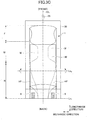
- FIG. 3A illustrates a top view (view from the side of the top sheet 3) of the absorbent article 1 mounted on the wrapping sheet 20 in a direction such that the back sheet 2 faces the wrapping sheet 20.
- the hip-hold flaps HF and HF on both sides of the main body 8 are folded with the top sheet 3 inward along the lengthwise direction folding lines Ly and Ly extending in a substantially lengthwise direction.
- the substantially lengthwise direction may be a direction extending in a lengthwise direction, that is, parallel to the centerline CL of lengthwise direction in the absorbent article 1.
- a direction may have an angle of 10° or less and preferably 5° or less from the centerline CL of the lengthwise direction.
- the rear area R of the absorbent article 1 is folded together with the wrapping sheet 20 in the lengthwise direction.
- a portion of the absorbent article 1 including the rear end thereof is folded with the top sheet 3 inward along a first-widthwise-direction folding line Lx1 extending in substantially a widthwise direction.
- the portion of the absorbent article 1 is folded so that the first-widthwise-direction folding line Lx1 passes through the anti-slipping portions 9 and 9 provided on the hip-hold flaps HF and HF.
- the portions where the anti-slipping portions 9 are provided are thicker, harder, and more rigid than the portions where the anti-slipping portions are not provided. For this reason, in the portions where the anti-slipping portions 9 are provided and their vicinities, a deformation in association with folding, deflection of the flaps, or slipping from the position folded in the widthwise direction is unlikely to occur.
- the first-widthwise-direction folding line Lx1 may pass through any position in the lengthwise direction of the anti-slipping portions 9. However, when the first-widthwise-direction folding line Lx1 passes through the center of the lengthwise direction of the anti-slipping portions 9, flexibility of the hip-hold flaps HF in front of or behind of the first-widthwise-direction folding line Lx1 can be suitably reduced (the hip-hold flaps HF can be provided with a balanced stiffness in front of or behind of the first-widthwise-direction folding line Lx1). Therefore, when the first-widthwise-direction folding line Lx1 is folded, the hip-hold flap HF does not expand in the width direction.
- the shape of the anti-slipping portions 9 is a rectangle having a longitudinal side in the lengthwise direction.
- the shape may be a square other than a rectangle or an elliptical shape.
- the shape of the outer shape of the anti-slipping portions 9 may be along the outline of the hip-hold flaps HF. That is, the edge of the outer shape in the widthwise direction of the anti-slipping portions 9 may be curved while maintaining a curve with a certain distance from the edge of the hip-hold flaps HF.
- the hip-hold flaps HF is capable of preventing the hip-hold flaps HF from spreading outward in the widthwise direction because the first-widthwise-direction folding line Lx1 passes through the anti-slipping portions 9 and through the apexes 11P of the convex portions 11 of the hip-hold flaps HF. Therefore, it is capable of preventing the hip-hold flaps HF from unintentionally protruding from the wrapping sheet 20 or overlapping the sealing position of the wrapping sheet 20 when the edges of the wrapping sheet 20 are sealed after the absorbent article 1 is folded together with the wrapping sheet 20. Accordingly, the width of the wrapping sheet 20 is no longer required to be large in view of spreading outward in the widthwise direction of the hip-hold flaps HF, thus capable of providing a compact individually wrapped absorbent article.
- the anti-slipping portions 9 are positioned so as to span a position of the apexes 11P of the convex portions 11 having the outline of the hip-hold flaps HF viewed in the lengthwise direction.
- the anti-slipping portions 9 are preferably arranged so as to span a position where the apexes of the widest convex portions are present.
- it is capable of folding at the widest position of the first-widthwise-direction folding line Lx1. Accordingly, the deformation and movement of the hip-hold flaps HF can be easily suppressed, and the hip-hold flaps spread outward in the widthwise direction can be effectively suppressed.
- a peeling sheet 30 can be disposed on the anti-slipping portions 9.
- the peeling sheet 30 is a sheet for protecting the anti-slipping function (adhesiveness, high friction, or the like) of the anti-slipping portions 9.
- the peeling sheet 30 is a sheet that can open the individually wrapped absorbent article and peel off the absorbent article 1 immediately before use to expose the anti-slipping portions 9.
- the peeling sheet 30 may be a sheet of paper; polyolefin-based films such as polypropylene, polyethylene, and the like; films such as polyester, polyvinyl alcohol, and the like; non-woven fabric; laminated non-woven fabric (including a non-woven polylaminated fabric); and the like, in which a mold-release treatment is applied to the surface abutting on the anti-slipping portions 9.
- the mold-release treatment can be formed by coating or spraying a mold-release treatment liquid such as silicone-based resin, fluorine-based resin, tetrafluoroethylene-based resin, and the like.
- the peeling sheet is not particularly limited as long as the peeling sheet can be easily peeled off from the anti-slipping portions 9 without performing the mold-releasing treatment and does not cause a decrease in adhesion or high friction of the anti-slipping portions 9. Therefore, the peeling sheet may be a film itself or a non-woven fabric itself.
- the peeling sheet 30 is also folded together with the hip-hold flaps HF and the anti-slipping portions 9 because the peeling sheet 30 is arranged to cover the anti-slipping portions 9.
- the hip-hold flaps HF and HF can be folded to the lengthwise direction while maintaining the plane shape because the peeling sheet 30 can hold the hip-hold flaps HF and HF in a plane shape along the portion in front of or behind of the first-widthwise-direction folding line Lx1. This further improves the aforementioned effect of suppressing the hip-hold flaps HF and the HF spreading outward in the widthwise direction ( FIG. 1 ).
- the peeling sheet 30 may have a rectangular shape as illustrated in FIG. 3B .
- the shape of the peeling sheet 30 is not particularly limited as long as the peeling sheet 30 can be disposed to cover the anti-slipping portions 9 in the folding process. Therefore, the shape of the peeling sheet is not limited to a rectangular shape but may be an elliptical shape.
- the peeling sheet 30 may be a sheet that covers both the wing-like flaps W having anti-slipping portions and the hip-hold flaps HF having anti-slipping portions.
- FIG. 3C illustrates a state after the absorbent article 1 is folded at the first-widthwise-direction folding line Lx1 illustrated in FIG. 3B . Then, the rear area R of the absorbent article 1 is folded with the top sheet 3 inward along a second-widthwise-direction folding line Lx2, which is positioned ahead of the first-widthwise-direction folding line Lx1.
- the second-widthwise-direction folding line Lx2 is preferably not included in the portion A corresponding to a body fluid excretion orifice, and more preferably not included in the middle area M.
- FIG. 3D illustrates a state of the absorbent article 1 after folding at the second-widthwise-direction folding line Lx2 illustrated in FIG. 3C . From the state of FIG. 3D , the area including the front end is folded with the top sheet 3 inward along a third-widthwise-direction folding line Lx3. A pouch tape 25 can then fasten the front end of the wrapping sheet 20.
- the absorbent article 1 is folded toward the lengthwise direction inward along three widthwise directional lines that are substantially perpendicular to the lengthwise direction.
- folding lines extended in the widthwise direction may be two, four, or more. This makes it easier to carry and store the absorbent article 1 because the elongated absorbent article can be made into a compact shape with a shorter length.
- the main body 8 of the absorbent article 1 may further be provided with a flexible portion 50, and the first-widthwise-direction folding line Lx1 may be formed as a line passing through the flexible portion 50 in the folding process described above.
- the flexible portion 50 is a portion that is more easily bent than the area around the flexible portion 50.
- the flexible portion 50 may be formed on at least one of the back sheet 2, the absorbent 4, or the top sheet 3.
- the flexible portion 50 can be a thinned portion of the back sheet 2, the absorbent 4, and the top sheet 3.
- the absorbent article 1 having the flexible portion 50 will be described.
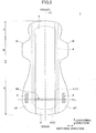
- FIG. 4 illustrates, as an example, an absorbent article 1 having compressed grooves 18.
- the absorbent article illustrated in FIG. 4 has essentially the same configuration as the absorbent article illustrated in FIG. 2A , but differs in having the compressed grooves 18.
- a plurality of compressed grooves 18 are formed across the front area F, the middle area M, and the rear area R.
- the compressed grooves 18 are formed linearly symmetrical with the centerline CL in the lengthwise direction as a target axis.
- the compressed grooves 18 may not necessarily be formed in a linear symmetry. As illustrated in FIG.
- the compressed grooves 18 may include a front compressed groove 18a, which is mainly provided in the front area F, a pair of central compressed grooves 18b, 18b extending in the lengthwise direction provided on both sides of the lengthwise centerline CL mainly from the middle area M to the rear area R, and a rear compressed groove 18c, which is provided near the rear end of the rear area R.
- Central compressed grooves 18b and 18b forming a pair, are connected to each other at the rear.
- a link portion 19 of the pair of central compressed grooves 18b and 18b both the top sheet 3 and the absorbent 4 are pressed, thereby the thickness of the link portion is reduced. Therefore, the main body 8 is easily bent at a position including the link portion 19.
- the first-widthwise-direction folding line Lx1 can be folded through the link portion 19 of the pair of central compressed grooves 18b and 18b upon folding ( FIGS. 3A to 3E ).
- folding at the first-widthwise-direction folding line Lx1 ( FIG. 3B ) becomes easier, and it is capable of stably maintaining the folded state even after folding.
- the link portion 19 of the pair of central compressed grooves 18b and 18b may be a compressed groove extending in the widthwise direction.
- the main body 8 can be more easily bent and more stably retained in a bent state by aligning the first-widthwise-direction folding line Lx1 along the compressed groove.
- the flexible portion 50 is a portion in which the absorbent 4 is not provided for the entire width.
- a configuration of the flexible portion 50 may alternately have a portion in which the absorbent 4 is present over the widthwise direction and have a portion in which the absorbent 4 is not present over the widthwise direction.
- it is capable of folding at the first-widthwise-direction folding line Lx1 through the flexible portion 50. That is, it is capable of folding between the absorbent portions 41 and 42 upon folding ( FIGS. 3A to 3E ). As a result, folding at the first-widthwise-direction folding line Lx1 ( FIG. 3B ) becomes easier, and it is capable of stably maintaining the folded state even after folding.
- the flexible portion 50 is a portion without the absorbent, but the thickness of the absorbent may be smaller than the front and rear portions thereof.
- an individually wrapped absorbent article includes: an absorbent article having a main body, the main body including a liquid-impermeable back sheet, an absorbent, and a liquid-permeable top sheet which are laminated in aforementioned order, the absorbent article having a predetermined length in a lengthwise direction and a predetermined width in a direction perpendicular to the lengthwise direction; and a wrapping sheet which wraps the absorbent article, wherein the absorbent article includes a middle area which includes a portion corresponding to a body fluid excretion orifice of a wearer upon mounting the absorbent article, and a rear area which is adjacent to a rear of the middle area and extends to a rear end of the absorbent article, wherein the absorbent article includes hip-hold flaps projecting laterally from the main body in the rear area, and an outline the hip-hold flaps has convex portions with a radius of curvature of 5 to 500 mm, wherein anti-slipping portions are disposed on a back of the
- the absorbent article in the embodiment described in Appendix 1 above has hip-hold flaps projecting laterally to the main body in the rear area.
- Such absorbent article with the hip-hold flaps can be an individually wrapped absorbent article by folding the hip-hold flaps widthwise toward the top sheet side at the lengthwise direction folding lines, then folded lengthwise toward the top sheet side at the widthwise direction folding line.
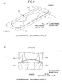
- hip-hold flaps HFa and HFa may spread outward in the widthwise direction and may protrude from a wrapping sheet 20a ( FIG. 1(a) and (b) ).
- hip-hold flaps having an outline including a convex portion having a radius of curvature of 5 to 500 mm is more likely to spread outward in the widthwise direction because the convex portion is relatively easy to move and is easily misaligned when folded.
- a widthwise direction folding line passes through anti-slipping portions disposed on the back of the hip-hold flaps.
- the portions where the anti-slipping portions are provided are thicker, harder, and more rigid than the portions where the anti-slipping portions are not provided. For this reason, it is unlikely that deformation of the portion in which the anti-slipping portions are provided or the portions in the vicinities thereof may occur in association with the folding thereof. Therefore, it is capable of preventing the hip-hold flaps from spreading outward in the widthwise direction ( FIG. 1(b) ) when the rear area is folded toward the lengthwise direction inward along the widthwise direction folding line.
- the rear area is folded at a position where the width of the folding is large in the widthwise direction because the widthwise direction folding line passes through the apexes of the convex portions of the hip-hold flaps.
- the convex portions of the hip-hold flaps are more difficult to move upon folding, and it is difficult to spread outward in the widthwise direction.
- the hip-hold flaps when the rear area is folded in the lengthwise direction, the hip-hold flaps can be suppressed from spreading outward. Therefore, it is capable of preventing the flap portion from protruding from a wrapping sheet or overlapping a sealing position of the wrapping sheet. Accordingly, the need to increase the width of the wrapping sheet is no longer required by considering the hip-hold flaps spread outward.
- the apexes are positioned rearward of the center in the rear area in the lengthwise direction.
- the hip-hold flaps have an outline with the apexes of the convex portions disposed rearward of the rear area. Therefore, it is capable of preventing the hip-hold flaps from hitting around legs and causing a feeling of discomfort, and the rear area can be applied to follow the shape of buttocks.
- the folding wrinkles may be caused rearward of the center in the rear area. That is, the folding wrinkles tend to be caused in a position far from the grooves of the buttocks. Therefore, it is capable of preventing the wearing feeling from being impaired by the folding wrinkles.
- a flexible portion is formed in the main body, and the widthwise direction folding line passing through the flexible portion.
- an absorbent article can be more easily folded at a widthwise direction folding line because the flexible portion is formed at a position passing through the widthwise direction folding line. Further, it is capable of preventing the hip-hold flaps from deforming and spreading outward in the widthwise direction even when vibration or the like is applied to the absorbent article in the folding process of the absorbent article because the state after folding can be stably maintained.
- the flexible portion includes a portion having a reduced thickness of the absorbent.
- the embodiment further includes a peeling sheet positioned so as to overlap exposed anti-slipping portions, in which the exposed anti-slipping portions are formed by folding the hip-hold flaps with the top sheet side inward along the lengthwise direction folding lines, wherein the peeling sheet is folded together with the hip-hold flaps at the widthwise direction folding line.
- the peeling sheet can hold the folded flaps in a plane shape from above the flaps that are folded in the widthwise direction at the lengthwise direction folding lines. Therefore, when the rear area is folded toward the lengthwise direction inward along the widthwise direction folding line, the effect of preventing the flaps from spreading outward in the widthwise direction can be improved.
Landscapes
- Health & Medical Sciences (AREA)
- Epidemiology (AREA)
- Engineering & Computer Science (AREA)
- Biomedical Technology (AREA)
- Heart & Thoracic Surgery (AREA)
- Vascular Medicine (AREA)
- Life Sciences & Earth Sciences (AREA)
- Animal Behavior & Ethology (AREA)
- General Health & Medical Sciences (AREA)
- Public Health (AREA)
- Veterinary Medicine (AREA)
- Dermatology (AREA)
- Physics & Mathematics (AREA)
- Fluid Mechanics (AREA)
- Mechanical Engineering (AREA)
- Manufacturing & Machinery (AREA)
- Absorbent Articles And Supports Therefor (AREA)
Abstract
Description
- The present invention relates to an individually wrapped absorbent article.
- As absorbent articles such as sanitary napkins, panty liners, incontinence pads, and the like, it is known that an absorbent is sandwiched between a liquid-permeable top sheet and a liquid-impermeable back sheet. Some of these absorbent articles are adapted for prolonged use or for short periods of time when large volumes of body fluid are discharged, with a main body of an absorbent article extending in a rear area and with flaps projecting from both sides of the rear side thereby extending the rear area.
- Absorbent articles are typically provided as an individual wrapped article wrapped with a wrapping sheet. Here, in the case of aforementioned absorbent article having the extended rear area, the flaps protruding from both sides are folded toward the main body of the absorbent article, and then tri-folded or quad-folded in the lengthwise direction and wrapped (for example,
FIG. 4 in Patent Document 1). - Patent Document 1:
Japanese Patent Application Laid-Open No. 2003-339764 - However, in the configuration described in
Patent Document 1, when the rear area is folded, the flaps that have been folded in the widthwise direction may inadvertently spread outward in the widthwise direction (Fig. 1(a) and (b) ). In such cases, the flaps might extend out of the wrapping sheet or overlap with the sealing position of the wrapping sheet. Therefore, the size of the individually wrapped may become larger than intended when the width of the wrapping sheet is increased to address such issues. Therefore, there is a need for a configuration in which the flaps can be folded so as not to spread outward in the widthwise direction in the absorbent article with the expanded rear area. - In view of the foregoing, one aspect of the invention is to provide an absorbent article that is compactly wrapped by reducing a spread of flaps in a widthwise direction upon folding.
- In one aspect of the invention, an individually wrapped absorbent article includes an absorbent article having a main body, the main body including a liquid-impermeable back sheet, an absorbent, and a liquid-permeable top sheet that are laminated in aforementioned order, the main body is the absorbent article having a predetermined length in a lengthwise direction and a predetermined width in a direction perpendicular to the lengthwise direction; and a wrapping sheet that wraps the absorbent article individually, wherein the absorbent article includes a middle area that includes a portion corresponding to a body fluid excretion orifice of a wearer upon wearing the absorbent article, and a rear area that is adjacently behind the middle area and extends to a rear end of the absorbent article, wherein the absorbent article includes hip-hold flaps projecting laterally from the main body in the rear area, and an outline of the hip-hold flaps has convex portions with a radius of curvature of 5 to 500 mm, wherein anti-slipping portions are disposed on a back surface of the hip-hold flaps, and wherein the hip-hold flaps are folded with a top sheet side inward along lengthwise direction folding lines extending substantially in the lengthwise direction, and the rear area is then folded with the top sheet side inward along a widthwise direction folding line extending substantially in the widthwise direction through the anti-slipping portions and apexes of the convex portions.
- According to one aspect of the invention, the invention is capable of providing an absorbent article that is compactly wrapped by reducing a spread of flaps in a widthwise direction upon folding.
-
-
FIG. 1 is a view illustrating a part of a process in which a conventional absorbent article is folded; -
FIG. 2A is a partially cutaway plan view of an absorbent article in one embodiment of the invention; -
FIG. 2B illustrates a cross-sectional view of line I-I ofFIG. 2A ; -
FIG. 3A illustrates a process of forming an individually wrapped absorbent article according to one aspect of the invention; -
FIG. 3B illustrates a process of forming an individually wrapped absorbent article according to one aspect of the invention; -
FIG. 3C illustrates a process of forming an individually wrapped absorbent article according to one aspect of the invention; -
FIG. 3D illustrates a process of forming an individually wrapped absorbent article according to one aspect of the invention; -
FIG. 3E illustrates a process of forming an individually wrapped absorbent article according to one aspect of the invention; -
FIG. 4 illustrates a variation of an absorbent article in one embodiment of the invention; and -
FIG. 5 illustrates a variation of an absorbent article in one embodiment of the invention. - Hereinafter, embodiments of the present invention will be described in detail with reference to the drawings. In each drawing, unless otherwise noted, the description of the same or corresponding structure may be omitted with the same reference numerals. Also, the drawings are schematic to aid in understanding the invention.
-
FIG. 2A illustrates a partially cutaway plan view ofabsorbent article 1 in one embodiment of the invention of the present invention.FIG. 2B illustrates a cross-sectional view of line I-I ofabsorbent article 1. As illustrated inFIGS. 2A and2B , theabsorbent article 1 includes a main body (absorbent article body) 8 having a liquid-impermeable back sheet 2, a liquid-permeable top sheet 3, and an absorbent 4 provided between thetop sheet 3 and theback sheet 2. When theabsorbent article 1 is worn, thetop sheet 3 contacts skin (skin side or top side), and theback sheet 2 is fixed to an underwear (underwear side or back side). Both sides of thetop sheet 3 of theabsorbent article 1 may be provided with side non-wovenfabrics - As illustrated in
FIG. 2A , amain body 8 has a predetermined length in a lengthwise direction, a predetermined width in a widthwise direction perpendicular to the lengthwise direction, and an overall elongated shape in the lengthwise direction. The width of themain body 8 is substantially constant in the illustrated example but may vary across the lengthwise direction. As illustrated inFIG. 2A , theabsorbent article 1 can have a generally symmetrical shape with respect to the centerline (centerline in lengthwise direction) CL extending in a lengthwise direction. The configuration of the absorbent article 1 (including the thickness and density of the absorbent 4) may be substantially symmetrical with the centerline as the axis of symmetry or may be asymmetric. - The length in the lengthwise direction (overall length of the main body 8) of
absorbent article 1 is not particularly limited but preferably 250 to 450 mm, and more preferably from 270 to 380 mm. The length of the widthwise direction of the main body 8 (the width of the absorbent 4) is not particularly limited but is preferably 50 to 200 mm, and is more preferably 70 to 120 mm. - The
absorbent article 1 has a portion A corresponding to a body fluid excretion orifice corresponding to a body fluid excretion orifice such as a vaginal opening of a wearer when the absorbent article is worn. The portion A corresponding to a body fluid excretion orifice has a center Ac. The center Ac is positioned on the centerline CL in the lengthwise direction and is positioned on the center of the lengthwise direction of the portion A corresponding to a body fluid excretion orifice. The position of the center Ac is 70 to 130 mm away from the front end of theabsorbent article 1. Further, the portion A corresponding to a body fluid excretion orifice may have a length (length in the lengthwise direction) of 10 to 50 mm and preferably 20 to 40 mm. The portion A corresponding to a body fluid excretion orifice may have a width (length in the widthwise direction) of 5 to 40 mm and preferably 10 mm to 30 mm. It should be noted that the shape and size of the portion A corresponding to a body fluid excretion orifice illustrated in the drawings are merely examples for ease of explanation. - The
absorbent article 1 has a middle area M including a portion corresponding to a body fluid excretion orifice A described above, a front area F in front of the middle area M, and a rear area R in behind of the middle area M. The middle area M corresponds approximately to the wearer's crotch when worn, and the rear area R corresponds approximately to the wearer's buttocks when worn. - The middle area M may have wing-like flaps W and W extending from both sides thereof to securely fix the
absorbent article 1 to an underwear upon mounting. The front area F is the area from the front origins or the near the front origins of the wing-like flaps W and W to the front end of the absorbent article. The rear area R is the area from the rear origins or near the rear origins of the wing-like flaps W and W to the rear end of the absorbent article. When the wing-like flaps W and W are provided, the position of the center Ac of the portion A corresponding to a body fluid excretion orifice in the lengthwise direction may be near the center of the sides in the wing-like flaps W and W in the lengthwise direction. - The
absorbent article 1 has wing-like flaps W and W. However, theabsorbent article 1 need not have wing-like flaps W and W. When it is assumed that the wing-like flaps W and W are formed, the area from the front origins or near the front origins of the wing-like flaps W and W to the front end of the absorbent article is determined as the front area F. When it is assumed that the wing-like flaps W and W are formed, the area from the rear origins or near the rear origins of the wing-like flaps W and W to the rear end of the absorbent article is determined as the rear area R. - The
back sheet 2 may be a sheet material having at least a water shielding property, such as an olefin-based resin sheet such as polyethylene or polypropylene. A laminated non-woven fabric made by laminating a non-woven material with a polyethylene sheet or the like or a non-woven sheet made to be substantially liquid-impermeable by interposing a waterproof film with the laminated material or the like can be used. In addition, from the viewpoint of preventing stuffiness, it is further desirable to use a material having moisture permeability. As a waterproof and moisture permeable sheet material, a microporous sheet or the like may be obtained by melt-kneading an inorganic filler into an olefinic-based resin such as polyethylene or polypropylene to form a sheet, followed by stretching the sheet in a monoaxial or a biaxial direction. - The
top sheet 3 is a liquid-permeable sheet through which bodily fluids such as menstrual blood, discharge, and urine pass. As thetop sheet 3, a porous or non-porous non-woven fabric or a porous plastic sheet is preferably used. As the material fibers constituting the non-woven fabric, for example, olefins such as polyethylene, polypropylene, and the like; synthetic fibers such as polyester, polyamide, and the like; regenerated fibers such as rayon, cupra, and the like; and blended fibers, as well as natural fibers such as cotton and the like can be used alone or in combination. Examples of non-woven fabric processing methods include a span lace method, a spunbond method, a thermal bond method, a melt-blown method, a needle punch method, and the like. Among these processing methods, the span lace method is preferably used from the view point of flexibility, the spunbond method is preferably used from the view point of producing a non-woven fabric with high drape properties, and the thermal bond method is preferably used from the view point of producing a non-woven fabric that is bulky and soft. Alternatively, composite fibers such as core-sheath type fibers with high melting point fibers as the core and low melting point fibers as the sheath, side-by-side type fibers, split type fibers, and the like may be used. - The materials of
absorbent 4 are not particularly limited as long as the materials are capable of absorbing and retaining body fluid. Cotton pulps and water absorbent polymers are preferably contained in the materials. Examples of the water absorbent polymers include superabsorbent polymer (SAP), superabsorbent polymer fiber (SAF), and a combination thereof. Examples of the pulps include cellulosic fibers such as chemical pulps obtained from woods, dissolved pulps, and the like; and artificial cellulose fibers such as rayon, acetate, and the like. Examples of raw materials for chemical pulps include hardwood, coniferous wood, and the like. Coniferous wood is preferably used because of its long fiber length. - Synthetic fibers may also be mixed with the
absorbent 4. Examples of the synthetic fibers include polyolefins such as polyethylene, polypropylene, and the like; polyesters such as polyethylene terephthalate, polybutylene terephthalate, and the like; polyamides such as nylon and the like; and copolymers thereof. Among these, two kinds of the synthetic fibers may be used in combination. Also, composite fibers such as core-sheath type fibers with high melting point fibers as the core and low melting point fibers as the sheath, side-by-side type fibers, split type fibers, and the like may be used. Alternatively, hydrophobic fibers may be surface-treated with a hydrophilic agent to confer affinity to body fluids. Theabsorbent 4 is preferably manufactured by laminating fibers or an air laid process. - The thickness of the
absorbent 4 is in the range of 0.3 to 30 mm and preferably in the range of 1.0 to 15 mm. The absorbent 4 as a whole need not have a uniform thickness across the entire surface, and the area of the portion A corresponding to a body fluid excretion orifice and its proximity may be inflated. - The absorbent 4 may be wrapped with a wrapped sheet formed from crepe paper or non-woven fabric to maintain its shape or the like. The absorbent 4 can be prevented from becoming warped or cracked by surrounding the absorbent with a packaging a packaging sheet. As the packaging sheet, a colorless (that is white) crepe paper or a non-woven material may be used, or a colored packaging sheet may be used. When a colored packaging sheet is used, the color of the packaging sheet can also be reflected as a light color from the
top sheet 3. Therefore, the color of the excreted body fluid can be close to the reflected color of thepackaging sheet 9 to make it inconspicuous. The packaging sheet can be colored, for example, as a complementary color of body fluids. For example, in an absorbent article (such as a sanitary napkin) configured for the purpose of absorbing blood, the packaging sheet can be colored green, which is the complementary color of red. - The side
non-woven fabric 7 may be formed from non-woven fabric materials that are subjected to an appropriate water-repellent treatment or hydrophilic treatment in accordance with the purpose of preventing the body fluid from penetrating or enhancing the feel against the skin. The non-woven materials may be, for example, natural fibers, synthetic fibers, regenerated fibers, and the like. For the water-repellent treatment of the sidenon-woven fabric 7, a water-repellent agent, such as a silicon-based material or a paraffin-based material, may be used. - At the front end and rear end of the
main body 8, the outer edges of theback sheet 2 and thetop sheet 3 are bonded by an adhesive method such as hot melt, heat seal, ultrasonic seal, or the like. Theside non-woven fabrics main body 8 and theback sheet 2 are bonded by at least one of the adhesive methods. Thus, the wing-like flaps W and W described above can be formed in the middle area M, and the hip-hold flaps HF and HF described below can be formed in the rear area R. - The
main body 8 may be provided with pressure grooves. The pressure grooves are grooves (also referred to as fitting embosses) that are obtained by laminating thetop sheet 3 and theabsorbent 4 and then pressurizing both of them together such that thetop sheet 3 side is depressed toward thesheet 2. The pressure grooves can be formed by laminating thetop sheet 3 onto theabsorbent 4 and passing the resulting laminate between a pair of pressurizing rolls. For example, a convex roll on the side of thetop sheet 3 of the laminate and a flat roll on the side of the absorbent 4 can be arranged and pressurized by both rolls. - As illustrated in
FIG. 2A , theabsorbent article 1 in the present embodiment is the rear area R expanded in the lengthwise direction and the widthwise direction. More specifically, themain body 8 extends in the lengthwise direction, and the hip-hold flaps HF and HF extend on both sides of thebody 8. The flexibility of the hip-hold flaps HF and HF allows them to be applied along round portion of the buttocks, and also causes them to readily conform to the movements of the buttocks. As illustrated inFIGS. 2A and2B , in the present embodiment, the hip-hold flaps HF and HF are formed by bonding theside non-woven fabrics back sheet 2, and do not include absorbent. However, the hip-hold flaps HF and HF may contain a thin absorbent as long as the absorbent can have flexibility to align with the round portions of the buttocks. - Thus, the
absorbent article 1 in the present embodiment has an extended rear area R. This effectively prevents leakage of body fluid in the rear area R. Accordingly, theabsorbent article 1 can be suitably used as a sanitary napkin for long-time or night-time use, because it can accommodate a situation where long hours of use is expected or a situation where a large amount of body fluid is excreted within a short period of time. - As illustrated in
FIG. 2A , the outline of the hip-hold flaps HF hasconvex portions 11 which are curved. That is, eachconvex portion 11 may have a convex-shaped outline with a center of curvature on the hip-hold flaps HF or themain body 8 in a planar view. The radius of curvature atapexes 11P of theconvex portions 11 may be 5 to 500 mm and preferably 35 to 200 mm. As described above, the hip-hold flaps HF have an external shape having a convex portion having a predetermined radius of curvature, so that the flat hip-hold flaps HF readily deform to match the curved surface of buttocks. Accordingly, the hip-hold flaps HF are easily moved from both ends of the convex portions. Therefore, the rear area R can be tightly attached to the curved surface of buttocks to improve the effectiveness of preventing leakage of body fluid in the rear area R. In addition, a feeling of discomfort when the edges of the hip-hold flaps HF and HF contact the skin can be reduced, because the contour is curved. - In the illustrated embodiment, the outline of each hip-hold flap HF is shaped to have one convex portion, but the convex portion of the hip-hold flap HF may be two or more. That is, the outline of the hip-hold flap HF may have irregularities. In such a case, each convex portion preferably has a radius of curvature in the range described above.
- The
absorbent article 1 may have a maximum width at a position where the hip-hold flap HF has a convex portion 11 (where the convex portion is two or more, the convex portion has the most protruding portion outward in the width direction). This maximum width is preferably 70 to 200 mm and more preferably 100 to 160 mm. - In addition, the position of the convex portion 11 (or the position of the maximum width when there are two or more convex portions) is preferably in a range from the position of the rear area R in the center of the lengthwise direction to the rear direction. This allows the wide part of the hip-hold flaps HF and HF to be positioned near the point where the buttocks groove (gluteal cleft) begins to become shallow and the buttocks groove ends. This prevents leakage of fluid that has moved to the rear through the buttocks groove in the lateral direction. In addition, it is capable of preventing the hip-hold flaps HF and HF from hitting around legs and causing a feeling of discomfort because the wide portion of the hip-hold flaps HF and HF can be moved away from the position where the pressure is easily applied from the legs.
- The
absorbent article 1 in the present embodiment is provided withanti-slipping portions 9 on the sides of theback sheet 2 for securing theabsorbent article 1 to underwear when worn. Theanti-slipping portions 9 are preferably disposed on theback sheet 2 side of themain body 8, the wing-shaped flaps W and W, and the hip-hold flaps HF and HF.FIG. 2A illustrates theanti-slipping portions 9 disposed on theback sheet 2 side of the hip-hold flaps HF and the HF. The other anti-slipping portions are omitted. - The materials used for the
anti-slipping portions 9 are not particularly limited as long as theabsorbent article 1 functions so as not to slip from the underwear. Theanti-slipping portions 9 can be formed as an adhesive layer or non-adhesive layer. Examples of adhesive layers include a styrene-based polymer, a tackifier, a plasticizer, and a combination thereof. Examples of the styrene-based polymer include a styrene-ethylene-butylene-styrene block copolymer, a styrene-butylene-styrene block copolymer, a styrene-isobutylene-styrene copolymer, a styrene-butadiene-styrene block copolymer, and the like. One or more types of styrene-butadiene-styrene block copolymers may be used. Among these, a styrene-butadiene-styrene block copolymer is preferably used from the view point of thermostability. - As a tackifier and a plasticizer, a solid material may be used at room temperature. Examples of the tackifiers include C5-based petroleum resins, C9-based petroleum resins, dicyclopentadiene-based petroleum resins, rosin-based petroleum resins, polyterpene resins, terpenephenol resins, and the like. Examples of the plasticizers include monomer plasticizers such as trifrecyl phosphate, dibutyl phthalate, and dioctyl phthalate, as well as polymer plasticizers such as vinyl polymers, polyesters, and the like.
- Examples of the materials of the
anti-slipping portions 9 that are formed as non-adhesive layers include a material using a base polymer such as natural rubber, styrene-butadiene rubber, silicone rubber, chloroprene rubber, butyl rubber, styrene-isoprene rubber, and the like. The material may be used alone or in combination. Among these, silicone rubber or hydrogenated type elastomers of SIS and SBS are preferably used. A mechanical fastener hook material may be used as theanti-slipping portions 9. The shape of the hook is not particularly limited as long as the hook is securable to the underwear, and a variety of publicly known shapes, such as a sauce shape, mushroom shape, or the like, may be used. - As illustrated in
FIG. 2A , theanti-slipping portions 9 may be provided along the lengthwise direction of the hip-hold flaps HF and HF. That is, theanti-slipping portions 9 may be provided along the lengthwise direction of theabsorbent article 1. Accordingly, theanti-slipping portions 9 have an elongated shape in the lengthwise direction as illustrated inFIG. 2A . - The length of the anti-slipping portions 9 (length in lengthwise direction) may be from 10 to 100 mm and preferably from 15 to 50 mm. The width (length in widthwise direction) of the
anti-slipping portions 9 may be from 0.3 to 20 mm and preferably from 0.5 to 15 mm. - The
anti-slipping portions 9 in the hip-hold flaps HF and HF may be provided as a contiguous single area or as a plurality of areas that are discontinuous in the lengthwise direction and/or the widthwise direction. - One embodiment of the present invention is an absorbent article (individually wrapped absorbent article) individually wrapped so that it can be easily and sanitarily carried. The individually wrapped absorbent article includes an
absorbent article 1 and awrapping sheet 20 as described above. The individually wrapped absorbent article may be formed by wrapping theabsorbent article 1 by folding thewrapping sheet 20, or by folding thewrapping sheet 20 along with theabsorbent article 1, after theabsorbent article 1 is mounted on thewrapping sheet 20, so that theabsorbent article 1 is not exposed. - The wrapping
sheet 20 is not particularly limited in configuration and size as long as the wrapping sheet can wrap theabsorbent article 1. For example, the wrappingsheet 20 may be rectangular in plan view as described below (FIG. 3A ). - The wrapping
sheet 20 may be a polyolefin-based film such as polypropylene, polyethylene, and the like; a film such as polyester, polyvinyl alcohol, and the like; a non-woven fabric; a laminated non-woven fabric (including a non-woven polylaminated fabric in which a polymeric layer is laminated on one or both surfaces of the non-woven fabric); and the like. The films are preferably used if a design by printing is desirable. The non-woven fabrics are preferably used if a texture, soft feel, or the like are desirable. - Referring to
FIGS. 3A to 3E , the folding and individually wrapping steps of the above-described absorbent article 1 (FIGS. 2A and2B ) with hip-hold flaps HF and HF having an outline with a radius of curvature of 5 to 500 mm will be described. For simplicity of description, the details of the structure of theabsorbent article 1 are omitted inFIGS. 3A to 3E . -
FIG. 3A illustrates a top view (view from the side of the top sheet 3) of theabsorbent article 1 mounted on thewrapping sheet 20 in a direction such that theback sheet 2 faces thewrapping sheet 20. When theabsorbent article 1 is folded, first, the hip-hold flaps HF and HF on both sides of themain body 8 are folded with thetop sheet 3 inward along the lengthwise direction folding lines Ly and Ly extending in a substantially lengthwise direction. - As used herein, the substantially lengthwise direction may be a direction extending in a lengthwise direction, that is, parallel to the centerline CL of lengthwise direction in the
absorbent article 1. Alternatively, a direction may have an angle of 10° or less and preferably 5° or less from the centerline CL of the lengthwise direction. The same shall apply to the substantially widthwise direction. That is, a direction may be parallel to the direction perpendicular to the centerline CL of the lengthwise direction, or a direction may be 10° or less and preferably 5° or less from the direction perpendicular to the centerline CL of the lengthwise direction. - The lengthwise direction folding lines Ly and Ly extend over the hip-hold flaps HF and HF so as to avoid areas where the
absorbent 4 is disposed. As illustrated inFIG. 3A , the lengthwise direction folding lines Ly and Ly preferably do not pass over theanti-slipping portions back sheet 2 side of the hip-hold flaps HF and HF. This makes it easier to fold the hip-hold flaps HF and HF in the widthwise direction. In addition, during the subsequent folding in the lengthwise direction, a situation where the absorbent article does not fold readily due to the excessive thickness and excessive bending stiffness can be prevented from occurring. In addition, the lengthwise direction folding lines Ly and Ly may pass over theanti-slipping portions -
FIG. 3B illustrates a state after the hip-hold flaps HF and HF are folded at the lengthwise direction folding lines Ly and Ly. In this state, the hip-hold flaps HF and HF are positioned inwardly from the ends of the widthwise direction in thewrapping sheet 20. - Beginning from the state illustrated in
FIG. 3B , the rear area R of theabsorbent article 1 is folded together with the wrappingsheet 20 in the lengthwise direction. First, as illustrated inFIG. 3B , a portion of theabsorbent article 1 including the rear end thereof is folded with thetop sheet 3 inward along a first-widthwise-direction folding line Lx1 extending in substantially a widthwise direction. At this time, the portion of theabsorbent article 1 is folded so that the first-widthwise-direction folding line Lx1 passes through theanti-slipping portions anti-slipping portions 9 are provided are thicker, harder, and more rigid than the portions where the anti-slipping portions are not provided. For this reason, in the portions where theanti-slipping portions 9 are provided and their vicinities, a deformation in association with folding, deflection of the flaps, or slipping from the position folded in the widthwise direction is unlikely to occur. - The hip-hold flaps HF of the present embodiment have an outline having a convex portion having a radius curvature of 5 to 500 mm so that the convex portion can be moved independently upon folding. However, even in this shape, when the first-widthwise-direction folding line Lx1 is folded so as to pass through the
anti-slipping portions 9, the hip-hold flaps HF are hardly deflected. Therefore, it is easy to retain the position folding in the widthwise direction. Accordingly, it is capable of preventing or suppressing the hip-hold flaps HF from spreading outward in the widthwise direction when the rear area is folded inward (Fig. 1(a) and (b) ). - The first-widthwise-direction folding line Lx1 may pass through any position in the lengthwise direction of the
anti-slipping portions 9. However, when the first-widthwise-direction folding line Lx1 passes through the center of the lengthwise direction of theanti-slipping portions 9, flexibility of the hip-hold flaps HF in front of or behind of the first-widthwise-direction folding line Lx1 can be suitably reduced (the hip-hold flaps HF can be provided with a balanced stiffness in front of or behind of the first-widthwise-direction folding line Lx1). Therefore, when the first-widthwise-direction folding line Lx1 is folded, the hip-hold flap HF does not expand in the width direction. - In the embodiment illustrated in the drawings, the shape of the
anti-slipping portions 9 is a rectangle having a longitudinal side in the lengthwise direction. However, the shape may be a square other than a rectangle or an elliptical shape. Further, the shape of the outer shape of theanti-slipping portions 9 may be along the outline of the hip-hold flaps HF. That is, the edge of the outer shape in the widthwise direction of theanti-slipping portions 9 may be curved while maintaining a curve with a certain distance from the edge of the hip-hold flaps HF. - Further, in the present embodiment, the first-widthwise-direction folding line Lx1 passes through the
apexes 11P of theconvex portions 11 of the hip-hold flaps HF. The first-widthwise-direction folding line Lx1 is a line extending substantially in the widthwise direction and may pass through theapexes 11P of one or bothconvex portions 11 of the two hip-hold flaps HF and HF. In the present specification, "passing through the apex of the convex portion" refers to passing through the apex and the vicinity of the convex portion. In an actual product, the folds are formed in a position that is preferably 8 mm or less and more preferably 5 mm or less in front of or behind from the apexes of the convex portions. - It is capable of folding at a position where the width of the folding is large (a position where the folded portion of the hip-hold flaps HF extends longer in the widthwise direction) as illustrated in
FIG. 3B . Accordingly, when it is folded at the first-widthwise-direction folding line Lx1, the portion in front of or behind the first-widthwise-direction folding line Lx1 of the hip-hold flaps HF is difficult to move, thereby preventing the hip-hold flaps HF from spreading outward in the widthwise direction (FIG. 1 ). - In this manner, it is capable of preventing the hip-hold flaps HF from spreading outward in the widthwise direction because the first-widthwise-direction folding line Lx1 passes through the
anti-slipping portions 9 and through theapexes 11P of theconvex portions 11 of the hip-hold flaps HF. Therefore, it is capable of preventing the hip-hold flaps HF from unintentionally protruding from the wrappingsheet 20 or overlapping the sealing position of thewrapping sheet 20 when the edges of thewrapping sheet 20 are sealed after theabsorbent article 1 is folded together with the wrappingsheet 20. Accordingly, the width of thewrapping sheet 20 is no longer required to be large in view of spreading outward in the widthwise direction of the hip-hold flaps HF, thus capable of providing a compact individually wrapped absorbent article. - In other words, the
anti-slipping portions 9 are positioned so as to span a position of theapexes 11P of theconvex portions 11 having the outline of the hip-hold flaps HF viewed in the lengthwise direction. Here, when the hip-hold flaps HF have a shape having a plurality ofconvex portions 11, theanti-slipping portions 9 are preferably arranged so as to span a position where the apexes of the widest convex portions are present. As a result, it is capable of folding at the widest position of the first-widthwise-direction folding line Lx1. Accordingly, the deformation and movement of the hip-hold flaps HF can be easily suppressed, and the hip-hold flaps spread outward in the widthwise direction can be effectively suppressed. - In a state illustrated in
FIG. 3B , a peelingsheet 30 can be disposed on theanti-slipping portions 9. The peelingsheet 30 is a sheet for protecting the anti-slipping function (adhesiveness, high friction, or the like) of theanti-slipping portions 9. The peelingsheet 30 is a sheet that can open the individually wrapped absorbent article and peel off theabsorbent article 1 immediately before use to expose theanti-slipping portions 9. - The peeling
sheet 30 may be a sheet of paper; polyolefin-based films such as polypropylene, polyethylene, and the like; films such as polyester, polyvinyl alcohol, and the like; non-woven fabric; laminated non-woven fabric (including a non-woven polylaminated fabric); and the like, in which a mold-release treatment is applied to the surface abutting on theanti-slipping portions 9. The mold-release treatment can be formed by coating or spraying a mold-release treatment liquid such as silicone-based resin, fluorine-based resin, tetrafluoroethylene-based resin, and the like. Note that the peeling sheet is not particularly limited as long as the peeling sheet can be easily peeled off from theanti-slipping portions 9 without performing the mold-releasing treatment and does not cause a decrease in adhesion or high friction of theanti-slipping portions 9. Therefore, the peeling sheet may be a film itself or a non-woven fabric itself. - When the
absorbent article 1 is folded at the first-widthwise-direction folding line Lx1, the peelingsheet 30 is also folded together with the hip-hold flaps HF and theanti-slipping portions 9 because the peelingsheet 30 is arranged to cover theanti-slipping portions 9. At this time, the hip-hold flaps HF and HF can be folded to the lengthwise direction while maintaining the plane shape because the peelingsheet 30 can hold the hip-hold flaps HF and HF in a plane shape along the portion in front of or behind of the first-widthwise-direction folding line Lx1. This further improves the aforementioned effect of suppressing the hip-hold flaps HF and the HF spreading outward in the widthwise direction (FIG. 1 ). - The peeling
sheet 30 may have a rectangular shape as illustrated inFIG. 3B . However, the shape of the peelingsheet 30 is not particularly limited as long as the peelingsheet 30 can be disposed to cover theanti-slipping portions 9 in the folding process. Therefore, the shape of the peeling sheet is not limited to a rectangular shape but may be an elliptical shape. Alternatively, when anti-slipping portions are provided on the wing-like flaps W and W, the peelingsheet 30 may be a sheet that covers both the wing-like flaps W having anti-slipping portions and the hip-hold flaps HF having anti-slipping portions. -
FIG. 3C illustrates a state after theabsorbent article 1 is folded at the first-widthwise-direction folding line Lx1 illustrated inFIG. 3B . Then, the rear area R of theabsorbent article 1 is folded with thetop sheet 3 inward along a second-widthwise-direction folding line Lx2, which is positioned ahead of the first-widthwise-direction folding line Lx1. The second-widthwise-direction folding line Lx2 is preferably not included in the portion A corresponding to a body fluid excretion orifice, and more preferably not included in the middle area M. -
FIG. 3D illustrates a state of theabsorbent article 1 after folding at the second-widthwise-direction folding line Lx2 illustrated inFIG. 3C . From the state ofFIG. 3D , the area including the front end is folded with thetop sheet 3 inward along a third-widthwise-direction folding line Lx3. Apouch tape 25 can then fasten the front end of thewrapping sheet 20. -
FIG. 3E illustrates an individually wrappedabsorbent article 100 folded at the third-widthwise-direction folding line Lx3 illustrated inFIG. 3D . In this state, both edges of thewrapping sheet 20 can be sealed by heat sealing, ultrasonic sealing, or the like. According to the present embodiment, it is capable of preventing the hip-hold flaps HF and HF from unintentionally sealing together when sealing both edges of the above-describedwrapping sheet 20 because the hip-hold flaps HF and HF are less likely to spread outward in the widthwise direction upon folding. - In the illustrated embodiment, the
absorbent article 1 is folded toward the lengthwise direction inward along three widthwise directional lines that are substantially perpendicular to the lengthwise direction. However, folding lines extended in the widthwise direction may be two, four, or more. This makes it easier to carry and store theabsorbent article 1 because the elongated absorbent article can be made into a compact shape with a shorter length. - The
main body 8 of theabsorbent article 1 may further be provided with aflexible portion 50, and the first-widthwise-direction folding line Lx1 may be formed as a line passing through theflexible portion 50 in the folding process described above. Theflexible portion 50 is a portion that is more easily bent than the area around theflexible portion 50. Theflexible portion 50 may be formed on at least one of theback sheet 2, theabsorbent 4, or thetop sheet 3. For example, theflexible portion 50 can be a thinned portion of theback sheet 2, theabsorbent 4, and thetop sheet 3. Hereinafter, theabsorbent article 1 having theflexible portion 50 will be described. -
FIG. 4 illustrates, as an example, anabsorbent article 1 having compressedgrooves 18. The absorbent article illustrated inFIG. 4 has essentially the same configuration as the absorbent article illustrated inFIG. 2A , but differs in having thecompressed grooves 18. As illustrated inFIG. 4 , a plurality ofcompressed grooves 18 are formed across the front area F, the middle area M, and the rear area R. Also, thecompressed grooves 18 are formed linearly symmetrical with the centerline CL in the lengthwise direction as a target axis. However, thecompressed grooves 18 may not necessarily be formed in a linear symmetry. As illustrated inFIG. 4 , thecompressed grooves 18 may include a frontcompressed groove 18a, which is mainly provided in the front area F, a pair of centralcompressed grooves compressed groove 18c, which is provided near the rear end of the rear area R. - Central
compressed grooves link portion 19 of the pair of centralcompressed grooves top sheet 3 and the absorbent 4 are pressed, thereby the thickness of the link portion is reduced. Therefore, themain body 8 is easily bent at a position including thelink portion 19. In this example, the first-widthwise-direction folding line Lx1 can be folded through thelink portion 19 of the pair of centralcompressed grooves FIGS. 3A to 3E ). As a result, folding at the first-widthwise-direction folding line Lx1 (FIG. 3B ) becomes easier, and it is capable of stably maintaining the folded state even after folding. - Thus, even if vibration or force is applied to the
absorbent article 1 from the outside and the vibration or force is transmitted to the hip-hold flaps HF and HF, the hip-hold flaps HF and HF do not easily deform and can be maintained in a folded state after theabsorbent article 1 is folded at the first-widthwise-direction folding line Lx1 in the individually wrapping process (folding process) of theabsorbent article 1. Therefore, the effect of preventing the hip-hold flaps HF and HF from spreading outward in the widthwise direction can be further enhanced. - The
link portion 19 of the pair of centralcompressed grooves main body 8 can be more easily bent and more stably retained in a bent state by aligning the first-widthwise-direction folding line Lx1 along the compressed groove. - Another modified example of
absorbent article 1 is illustrated inFIG. 5 . The example illustrated inFIG. 5 has the same configuration as that of theabsorbent article 1 illustrated inFIG. 2A , except that aflexible portion 50 is provided in theabsorbent 4. As illustrated inFIG. 5 , themain body 8 has theflexible portion 50 in the rear area R. In the present example, theflexible portion 50 is a portion in which theabsorbent 4 is not provided. That is, theabsorbent 4 is divided into anabsorbent portion 41 and anabsorbent portion 42 disposed behind theabsorbent portion 41. Theflexible portion 50 is formed between the absorbent portions. - In the illustrated example, the
flexible portion 50 is a portion in which theabsorbent 4 is not provided for the entire width. However, a configuration of theflexible portion 50 may alternately have a portion in which theabsorbent 4 is present over the widthwise direction and have a portion in which theabsorbent 4 is not present over the widthwise direction. - In this example, it is capable of folding at the first-widthwise-direction folding line Lx1 through the
flexible portion 50. That is, it is capable of folding between theabsorbent portions FIGS. 3A to 3E ). As a result, folding at the first-widthwise-direction folding line Lx1 (FIG. 3B ) becomes easier, and it is capable of stably maintaining the folded state even after folding. - In the illustrated example, the
flexible portion 50 is a portion without the absorbent, but the thickness of the absorbent may be smaller than the front and rear portions thereof. - Hereinafter, preferred embodiments of the present invention will be described.
- In an embodiment described in Appendix 1, an individually wrapped absorbent article includes: an absorbent article having a main body, the main body including a liquid-impermeable back sheet, an absorbent, and a liquid-permeable top sheet which are laminated in aforementioned order, the absorbent article having a predetermined length in a lengthwise direction and a predetermined width in a direction perpendicular to the lengthwise direction; and a wrapping sheet which wraps the absorbent article, wherein the absorbent article includes a middle area which includes a portion corresponding to a body fluid excretion orifice of a wearer upon mounting the absorbent article, and a rear area which is adjacent to a rear of the middle area and extends to a rear end of the absorbent article, wherein the absorbent article includes hip-hold flaps projecting laterally from the main body in the rear area, and an outline the hip-hold flaps has convex portions with a radius of curvature of 5 to 500 mm, wherein anti-slipping portions are disposed on a back of the hip-hold flaps, and wherein the hip-hold flaps are folded with a top sheet side inward along lengthwise direction folding lines extending substantially in the lengthwise direction, and the rear area is then folded with the top sheet side inward along a widthwise direction folding line extending substantially in the widthwise direction through the anti-slipping portions and apexes of the convex portions.
- The absorbent article in the embodiment described in
Appendix 1 above has hip-hold flaps projecting laterally to the main body in the rear area. Such absorbent article with the hip-hold flaps can be an individually wrapped absorbent article by folding the hip-hold flaps widthwise toward the top sheet side at the lengthwise direction folding lines, then folded lengthwise toward the top sheet side at the widthwise direction folding line. In a conventionalabsorbent article 1a, hip-hold flaps HFa and HFa may spread outward in the widthwise direction and may protrude from awrapping sheet 20a (FIG. 1(a) and (b) ). In particular, hip-hold flaps having an outline including a convex portion having a radius of curvature of 5 to 500 mm is more likely to spread outward in the widthwise direction because the convex portion is relatively easy to move and is easily misaligned when folded. - In contrast, in this embodiment, a widthwise direction folding line passes through anti-slipping portions disposed on the back of the hip-hold flaps. The portions where the anti-slipping portions are provided are thicker, harder, and more rigid than the portions where the anti-slipping portions are not provided. For this reason, it is unlikely that deformation of the portion in which the anti-slipping portions are provided or the portions in the vicinities thereof may occur in association with the folding thereof. Therefore, it is capable of preventing the hip-hold flaps from spreading outward in the widthwise direction (
FIG. 1(b) ) when the rear area is folded toward the lengthwise direction inward along the widthwise direction folding line. - In addition, the rear area is folded at a position where the width of the folding is large in the widthwise direction because the widthwise direction folding line passes through the apexes of the convex portions of the hip-hold flaps. As a result, the convex portions of the hip-hold flaps are more difficult to move upon folding, and it is difficult to spread outward in the widthwise direction.
- Thus, according to the present embodiment, when the rear area is folded in the lengthwise direction, the hip-hold flaps can be suppressed from spreading outward. Therefore, it is capable of preventing the flap portion from protruding from a wrapping sheet or overlapping a sealing position of the wrapping sheet. Accordingly, the need to increase the width of the wrapping sheet is no longer required by considering the hip-hold flaps spread outward.
- In the embodiment described in
Appendix 2, the apexes are positioned rearward of the center in the rear area in the lengthwise direction. - According to the embodiment described in
Appendix 2 above, the hip-hold flaps have an outline with the apexes of the convex portions disposed rearward of the rear area. Therefore, it is capable of preventing the hip-hold flaps from hitting around legs and causing a feeling of discomfort, and the rear area can be applied to follow the shape of buttocks. In addition, even if folding wrinkles extending to the widthwise direction in the rear area are caused, the folding wrinkles may be caused rearward of the center in the rear area. That is, the folding wrinkles tend to be caused in a position far from the grooves of the buttocks. Therefore, it is capable of preventing the wearing feeling from being impaired by the folding wrinkles. - In the embodiment according to
Appendix 3, a flexible portion is formed in the main body, and the widthwise direction folding line passing through the flexible portion. - According to the above-described embodiment of
Appendix 3, an absorbent article can be more easily folded at a widthwise direction folding line because the flexible portion is formed at a position passing through the widthwise direction folding line. Further, it is capable of preventing the hip-hold flaps from deforming and spreading outward in the widthwise direction even when vibration or the like is applied to the absorbent article in the folding process of the absorbent article because the state after folding can be stably maintained. - In the embodiment described in
Appendix 4, the flexible portion includes a portion having a reduced thickness of the absorbent. - According to the embodiment described in
Appendix 4, it is relatively easy to form a flexible portion. - In the embodiment described in Appendix 5, the embodiment further includes a peeling sheet positioned so as to overlap exposed anti-slipping portions, in which the exposed anti-slipping portions are formed by folding the hip-hold flaps with the top sheet side inward along the lengthwise direction folding lines, wherein the peeling sheet is folded together with the hip-hold flaps at the widthwise direction folding line.
- According to the embodiment described in Appendix 5 above, the peeling sheet can hold the folded flaps in a plane shape from above the flaps that are folded in the widthwise direction at the lengthwise direction folding lines. Therefore, when the rear area is folded toward the lengthwise direction inward along the widthwise direction folding line, the effect of preventing the flaps from spreading outward in the widthwise direction can be improved.
- This application claims priority under
Japanese Patent Office Application No. 2018-182208, filed September 27, 2018 -
- 1: Absorbent article
- 2: Back sheet
- 3: Top sheet
- 4: Absorbent
- 7: Side non-woven fabric
- 8: Main body of absorbent article
- 9: Anti-slipping portion
- 11: Convex portion
- 11P: Apex of convex portion
- 18, 18a, 18b, and 18c: Compressed grooves
- 19: Link portion of central compressed groove
- 20: Wrapping sheet
- 25: Pouch tape
- 30: Peeling sheet
- 41, 42: Absorbent portions
- 50: Flexible portion
- 100: Individually wrapped absorbent article
- A: Portion corresponding to a body fluid excretion orifice
- CL: Centerline in lengthwise direction
- F: Front area
- HF: Hip-hold flap
- M: Middle area
- R: Rear area
- W: Wing-like flap
Claims (5)
- An individually wrapped absorbent article comprising:an absorbent article having a main body, the main body including a liquid-impermeable back sheet, an absorbent, and a liquid-permeable top sheet that are laminated in aforementioned order, the main body is the absorbent article having a predetermined length in a lengthwise direction and a predetermined width in a direction perpendicular to the lengthwise direction; anda wrapping sheet that wraps the absorbent article individually,wherein the absorbent article includes a middle area that includes a portion corresponding to a body fluid excretion orifice of a wearer upon wearing the absorbent article, and a rear area that is adjacently behind the middle area and extends to a rear end of the absorbent article,wherein the absorbent article includes hip-hold flaps projecting laterally from the main body in the rear area, and an outline of the hip-hold flaps has convex portions with a radius of curvature of 5 to 500 mm,wherein anti-slipping portions are disposed on a back surface of the hip-hold flaps, andwherein the hip-hold flaps are folded with a top sheet side inward along lengthwise direction folding lines extending substantially in the lengthwise direction, and the rear area is then folded with the top sheet side inward along a widthwise direction folding line extending substantially in the widthwise direction through the anti-slipping portions and apexes of the convex portions.
- The individually wrapped absorbent article according to claim 1, wherein the apexes are positioned rearward of the center in the rear area in the lengthwise direction.
- The individually wrapped absorbent article according to claim 1, wherein a flexible portion is formed in the main body, and the widthwise direction folding line passing through the flexible portion.
- The individually wrapped absorbent article according to claim 3, wherein the flexible portion includes a portion having a reduced thickness of the absorbent.
- The individually wrapped absorbent article according to claim 1, further comprising a peeling sheet positioned so as to overlap exposed anti-slipping portions, in which the exposed anti-slipping portions are formed by folding the hip-hold flaps with the top sheet side inward along the lengthwise direction folding lines,
wherein the peeling sheet is folded together with the hip-hold flaps at the widthwise direction folding line.
Applications Claiming Priority (2)
| Application Number | Priority Date | Filing Date | Title |
|---|---|---|---|
| JP2018182208A JP2020048947A (en) | 2018-09-27 | 2018-09-27 | Individually packaged absorbent article |
| PCT/JP2019/027343 WO2020066221A1 (en) | 2018-09-27 | 2019-07-10 | Individually packaged absorbent article |
Publications (3)
| Publication Number | Publication Date |
|---|---|
| EP3858308A1 true EP3858308A1 (en) | 2021-08-04 |
| EP3858308A4 EP3858308A4 (en) | 2021-12-01 |
| EP3858308B1 EP3858308B1 (en) | 2023-08-30 |
Family
ID=69953087
Family Applications (1)
| Application Number | Title | Priority Date | Filing Date |
|---|---|---|---|
| EP19864268.8A Active EP3858308B1 (en) | 2018-09-27 | 2019-07-10 | Individually packaged absorbent article |
Country Status (7)
| Country | Link |
|---|---|
| US (1) | US20220110799A1 (en) |
| EP (1) | EP3858308B1 (en) |
| JP (1) | JP2020048947A (en) |
| KR (1) | KR20210064204A (en) |
| CN (1) | CN112739297A (en) |
| RU (1) | RU2771274C1 (en) |
| WO (1) | WO2020066221A1 (en) |
Families Citing this family (1)
| Publication number | Priority date | Publication date | Assignee | Title |
|---|---|---|---|---|
| USD963846S1 (en) * | 2019-10-11 | 2022-09-13 | Zhuhai Jianlang Daily Necessities Co., Ltd. | Anti-leakage sanitary napkin |
Family Cites Families (21)
| Publication number | Priority date | Publication date | Assignee | Title |
|---|---|---|---|---|
| JP3824452B2 (en) * | 1999-07-30 | 2006-09-20 | 花王株式会社 | Absorbent article packaging |
| JP4393015B2 (en) * | 2001-06-01 | 2010-01-06 | 花王株式会社 | Absorbent packaging structure |
| JP3824556B2 (en) | 2002-05-24 | 2006-09-20 | 花王株式会社 | Absorbent packaging structure |
| JP4421223B2 (en) * | 2003-06-20 | 2010-02-24 | ユニ・チャーム株式会社 | Sanitary napkin |
| JP4522073B2 (en) * | 2003-10-24 | 2010-08-11 | ユニ・チャーム株式会社 | Disposable wearing articles |
| JP4922802B2 (en) * | 2007-03-26 | 2012-04-25 | ユニ・チャーム株式会社 | Absorbent articles |
| JP5075600B2 (en) * | 2007-12-03 | 2012-11-21 | 花王株式会社 | Folding structure of absorbent articles |
| JP5112845B2 (en) * | 2007-12-27 | 2013-01-09 | 花王株式会社 | Absorbent package |
| JP5380095B2 (en) * | 2009-02-05 | 2014-01-08 | 花王株式会社 | Absorbent package |
| JP5697342B2 (en) * | 2010-02-03 | 2015-04-08 | ユニ・チャーム株式会社 | Packaging structure for absorbent article and method for producing packaging structure |
| JP5576194B2 (en) * | 2010-06-29 | 2014-08-20 | ユニ・チャーム株式会社 | Packaging structure |
| JP5528953B2 (en) * | 2010-08-31 | 2014-06-25 | 大王製紙株式会社 | Absorbent article and individual absorbent article |
| MX351547B (en) * | 2011-12-19 | 2017-10-17 | Kimberly Clark Worldwide Incorporated | Individually packaged absorbent article. |
| JP6420724B2 (en) * | 2015-06-08 | 2018-11-07 | ユニ・チャーム株式会社 | Absorbent articles |
| JP6591833B2 (en) * | 2015-08-28 | 2019-10-16 | 大王製紙株式会社 | Absorbent articles |
| JP6596706B2 (en) * | 2015-10-28 | 2019-10-30 | 日本製紙クレシア株式会社 | Absorbent articles |
| JP6141392B2 (en) * | 2015-11-12 | 2017-06-07 | ユニ・チャーム株式会社 | Absorbent articles |
| CN109414359A (en) * | 2016-06-24 | 2019-03-01 | 尤妮佳股份有限公司 | Absorbent commodity |
| JP6211151B1 (en) * | 2016-07-27 | 2017-10-11 | 大王製紙株式会社 | Absorbent articles |
| JP6360539B2 (en) * | 2016-11-25 | 2018-07-18 | 大王製紙株式会社 | Individual absorbent article, absorbent article, and method for folding absorbent article |
| JP2018182208A (en) | 2017-04-19 | 2018-11-15 | 株式会社村田製作所 | Coil component |
-
2018
- 2018-09-27 JP JP2018182208A patent/JP2020048947A/en active Pending
-
2019
- 2019-07-10 CN CN201980062281.4A patent/CN112739297A/en active Pending
- 2019-07-10 RU RU2021107056A patent/RU2771274C1/en active
- 2019-07-10 EP EP19864268.8A patent/EP3858308B1/en active Active
- 2019-07-10 US US17/268,661 patent/US20220110799A1/en not_active Abandoned
- 2019-07-10 WO PCT/JP2019/027343 patent/WO2020066221A1/en not_active Ceased
- 2019-07-10 KR KR1020217008001A patent/KR20210064204A/en not_active Ceased
Also Published As
| Publication number | Publication date |
|---|---|
| RU2771274C1 (en) | 2022-04-29 |
| EP3858308B1 (en) | 2023-08-30 |
| EP3858308A4 (en) | 2021-12-01 |
| WO2020066221A1 (en) | 2020-04-02 |
| KR20210064204A (en) | 2021-06-02 |
| CN112739297A (en) | 2021-04-30 |
| US20220110799A1 (en) | 2022-04-14 |
| JP2020048947A (en) | 2020-04-02 |
Similar Documents
| Publication | Publication Date | Title |
|---|---|---|
| JP6360539B2 (en) | Individual absorbent article, absorbent article, and method for folding absorbent article | |
| US11219561B2 (en) | Absorbent article | |
| CN104771275B (en) | absorbent article | |
| JP6351354B2 (en) | Absorbent articles | |
| JP6591833B2 (en) | Absorbent articles | |
| EP3858308B1 (en) | Individually packaged absorbent article | |
| US20220387231A1 (en) | Absorbent article | |
| JP7643777B2 (en) | Absorbent articles | |
| JP7658871B2 (en) | Absorbent articles | |
| JP7516227B2 (en) | Absorbent articles | |
| WO2019044965A1 (en) | Absorbent article | |
| WO2026069858A1 (en) | Absorbent article | |
| EP4129254A1 (en) | Individually packaged absorbent article | |
| JP5934506B2 (en) | Absorbent articles |
Legal Events
| Date | Code | Title | Description |
|---|---|---|---|
| STAA | Information on the status of an ep patent application or granted ep patent |
Free format text: STATUS: THE INTERNATIONAL PUBLICATION HAS BEEN MADE |
|
| PUAI | Public reference made under article 153(3) epc to a published international application that has entered the european phase |
Free format text: ORIGINAL CODE: 0009012 |
|
| STAA | Information on the status of an ep patent application or granted ep patent |
Free format text: STATUS: REQUEST FOR EXAMINATION WAS MADE |
|
| 17P | Request for examination filed |
Effective date: 20210224 |
|
| AK | Designated contracting states |
Kind code of ref document: A1 Designated state(s): AL AT BE BG CH CY CZ DE DK EE ES FI FR GB GR HR HU IE IS IT LI LT LU LV MC MK MT NL NO PL PT RO RS SE SI SK SM TR |
|
| A4 | Supplementary search report drawn up and despatched |
Effective date: 20211103 |
|
| RIC1 | Information provided on ipc code assigned before grant |
Ipc: A61F 13/56 20060101ALI20211027BHEP Ipc: A61F 13/475 20060101ALI20211027BHEP Ipc: A61F 13/47 20060101ALI20211027BHEP Ipc: A61F 13/15 20060101AFI20211027BHEP |
|
| DAV | Request for validation of the european patent (deleted) | ||
| DAX | Request for extension of the european patent (deleted) | ||
| GRAP | Despatch of communication of intention to grant a patent |
Free format text: ORIGINAL CODE: EPIDOSNIGR1 |
|
| STAA | Information on the status of an ep patent application or granted ep patent |
Free format text: STATUS: GRANT OF PATENT IS INTENDED |
|
| INTG | Intention to grant announced |
Effective date: 20230301 |
|
| GRAS | Grant fee paid |
Free format text: ORIGINAL CODE: EPIDOSNIGR3 |
|
| GRAA | (expected) grant |
Free format text: ORIGINAL CODE: 0009210 |
|
| STAA | Information on the status of an ep patent application or granted ep patent |
Free format text: STATUS: THE PATENT HAS BEEN GRANTED |
|
| AK | Designated contracting states |
Kind code of ref document: B1 Designated state(s): AL AT BE BG CH CY CZ DE DK EE ES FI FR GB GR HR HU IE IS IT LI LT LU LV MC MK MT NL NO PL PT RO RS SE SI SK SM TR |
|
| REG | Reference to a national code |
Ref country code: GB Ref legal event code: FG4D |
|
| REG | Reference to a national code |
Ref country code: CH Ref legal event code: EP |
|
| REG | Reference to a national code |
Ref country code: DE Ref legal event code: R096 Ref document number: 602019036428 Country of ref document: DE |
|
| REG | Reference to a national code |
Ref country code: IE Ref legal event code: FG4D |
|
| REG | Reference to a national code |
Ref country code: LT Ref legal event code: MG9D |
|
| REG | Reference to a national code |
Ref country code: NL Ref legal event code: MP Effective date: 20230830 |
|
| REG | Reference to a national code |
Ref country code: AT Ref legal event code: MK05 Ref document number: 1604468 Country of ref document: AT Kind code of ref document: T Effective date: 20230830 |
|
| PG25 | Lapsed in a contracting state [announced via postgrant information from national office to epo] |
Ref country code: GR Free format text: LAPSE BECAUSE OF FAILURE TO SUBMIT A TRANSLATION OF THE DESCRIPTION OR TO PAY THE FEE WITHIN THE PRESCRIBED TIME-LIMIT Effective date: 20231201 |
|
| PG25 | Lapsed in a contracting state [announced via postgrant information from national office to epo] |
Ref country code: IS Free format text: LAPSE BECAUSE OF FAILURE TO SUBMIT A TRANSLATION OF THE DESCRIPTION OR TO PAY THE FEE WITHIN THE PRESCRIBED TIME-LIMIT Effective date: 20231230 |
|
| PG25 | Lapsed in a contracting state [announced via postgrant information from national office to epo] |
Ref country code: SE Free format text: LAPSE BECAUSE OF FAILURE TO SUBMIT A TRANSLATION OF THE DESCRIPTION OR TO PAY THE FEE WITHIN THE PRESCRIBED TIME-LIMIT Effective date: 20230830 Ref country code: RS Free format text: LAPSE BECAUSE OF FAILURE TO SUBMIT A TRANSLATION OF THE DESCRIPTION OR TO PAY THE FEE WITHIN THE PRESCRIBED TIME-LIMIT Effective date: 20230830 Ref country code: NO Free format text: LAPSE BECAUSE OF FAILURE TO SUBMIT A TRANSLATION OF THE DESCRIPTION OR TO PAY THE FEE WITHIN THE PRESCRIBED TIME-LIMIT Effective date: 20231130 Ref country code: LV Free format text: LAPSE BECAUSE OF FAILURE TO SUBMIT A TRANSLATION OF THE DESCRIPTION OR TO PAY THE FEE WITHIN THE PRESCRIBED TIME-LIMIT Effective date: 20230830 Ref country code: LT Free format text: LAPSE BECAUSE OF FAILURE TO SUBMIT A TRANSLATION OF THE DESCRIPTION OR TO PAY THE FEE WITHIN THE PRESCRIBED TIME-LIMIT Effective date: 20230830 Ref country code: IS Free format text: LAPSE BECAUSE OF FAILURE TO SUBMIT A TRANSLATION OF THE DESCRIPTION OR TO PAY THE FEE WITHIN THE PRESCRIBED TIME-LIMIT Effective date: 20231230 Ref country code: HR Free format text: LAPSE BECAUSE OF FAILURE TO SUBMIT A TRANSLATION OF THE DESCRIPTION OR TO PAY THE FEE WITHIN THE PRESCRIBED TIME-LIMIT Effective date: 20230830 Ref country code: GR Free format text: LAPSE BECAUSE OF FAILURE TO SUBMIT A TRANSLATION OF THE DESCRIPTION OR TO PAY THE FEE WITHIN THE PRESCRIBED TIME-LIMIT Effective date: 20231201 Ref country code: FI Free format text: LAPSE BECAUSE OF FAILURE TO SUBMIT A TRANSLATION OF THE DESCRIPTION OR TO PAY THE FEE WITHIN THE PRESCRIBED TIME-LIMIT Effective date: 20230830 Ref country code: AT Free format text: LAPSE BECAUSE OF FAILURE TO SUBMIT A TRANSLATION OF THE DESCRIPTION OR TO PAY THE FEE WITHIN THE PRESCRIBED TIME-LIMIT Effective date: 20230830 |
|
| PG25 | Lapsed in a contracting state [announced via postgrant information from national office to epo] |
Ref country code: PL Free format text: LAPSE BECAUSE OF FAILURE TO SUBMIT A TRANSLATION OF THE DESCRIPTION OR TO PAY THE FEE WITHIN THE PRESCRIBED TIME-LIMIT Effective date: 20230830 Ref country code: NL Free format text: LAPSE BECAUSE OF FAILURE TO SUBMIT A TRANSLATION OF THE DESCRIPTION OR TO PAY THE FEE WITHIN THE PRESCRIBED TIME-LIMIT Effective date: 20230830 |
|
| PG25 | Lapsed in a contracting state [announced via postgrant information from national office to epo] |
Ref country code: ES Free format text: LAPSE BECAUSE OF FAILURE TO SUBMIT A TRANSLATION OF THE DESCRIPTION OR TO PAY THE FEE WITHIN THE PRESCRIBED TIME-LIMIT Effective date: 20230830 |
|
| PG25 | Lapsed in a contracting state [announced via postgrant information from national office to epo] |
Ref country code: SM Free format text: LAPSE BECAUSE OF FAILURE TO SUBMIT A TRANSLATION OF THE DESCRIPTION OR TO PAY THE FEE WITHIN THE PRESCRIBED TIME-LIMIT Effective date: 20230830 Ref country code: RO Free format text: LAPSE BECAUSE OF FAILURE TO SUBMIT A TRANSLATION OF THE DESCRIPTION OR TO PAY THE FEE WITHIN THE PRESCRIBED TIME-LIMIT Effective date: 20230830 Ref country code: ES Free format text: LAPSE BECAUSE OF FAILURE TO SUBMIT A TRANSLATION OF THE DESCRIPTION OR TO PAY THE FEE WITHIN THE PRESCRIBED TIME-LIMIT Effective date: 20230830 Ref country code: EE Free format text: LAPSE BECAUSE OF FAILURE TO SUBMIT A TRANSLATION OF THE DESCRIPTION OR TO PAY THE FEE WITHIN THE PRESCRIBED TIME-LIMIT Effective date: 20230830 Ref country code: DK Free format text: LAPSE BECAUSE OF FAILURE TO SUBMIT A TRANSLATION OF THE DESCRIPTION OR TO PAY THE FEE WITHIN THE PRESCRIBED TIME-LIMIT Effective date: 20230830 Ref country code: CZ Free format text: LAPSE BECAUSE OF FAILURE TO SUBMIT A TRANSLATION OF THE DESCRIPTION OR TO PAY THE FEE WITHIN THE PRESCRIBED TIME-LIMIT Effective date: 20230830 Ref country code: PT Free format text: LAPSE BECAUSE OF FAILURE TO SUBMIT A TRANSLATION OF THE DESCRIPTION OR TO PAY THE FEE WITHIN THE PRESCRIBED TIME-LIMIT Effective date: 20240102 Ref country code: SK Free format text: LAPSE BECAUSE OF FAILURE TO SUBMIT A TRANSLATION OF THE DESCRIPTION OR TO PAY THE FEE WITHIN THE PRESCRIBED TIME-LIMIT Effective date: 20230830 |
|
| PG25 | Lapsed in a contracting state [announced via postgrant information from national office to epo] |
Ref country code: IT Free format text: LAPSE BECAUSE OF FAILURE TO SUBMIT A TRANSLATION OF THE DESCRIPTION OR TO PAY THE FEE WITHIN THE PRESCRIBED TIME-LIMIT Effective date: 20230830 |
|
| REG | Reference to a national code |
Ref country code: DE Ref legal event code: R097 Ref document number: 602019036428 Country of ref document: DE |
|
| PLBE | No opposition filed within time limit |
Free format text: ORIGINAL CODE: 0009261 |
|
| STAA | Information on the status of an ep patent application or granted ep patent |
Free format text: STATUS: NO OPPOSITION FILED WITHIN TIME LIMIT |
|
| PG25 | Lapsed in a contracting state [announced via postgrant information from national office to epo] |
Ref country code: SI Free format text: LAPSE BECAUSE OF FAILURE TO SUBMIT A TRANSLATION OF THE DESCRIPTION OR TO PAY THE FEE WITHIN THE PRESCRIBED TIME-LIMIT Effective date: 20230830 |
|
| 26N | No opposition filed |
Effective date: 20240603 |
|
| PG25 | Lapsed in a contracting state [announced via postgrant information from national office to epo] |
Ref country code: BG Free format text: LAPSE BECAUSE OF FAILURE TO SUBMIT A TRANSLATION OF THE DESCRIPTION OR TO PAY THE FEE WITHIN THE PRESCRIBED TIME-LIMIT Effective date: 20230830 |
|
| PG25 | Lapsed in a contracting state [announced via postgrant information from national office to epo] |
Ref country code: BG Free format text: LAPSE BECAUSE OF FAILURE TO SUBMIT A TRANSLATION OF THE DESCRIPTION OR TO PAY THE FEE WITHIN THE PRESCRIBED TIME-LIMIT Effective date: 20230830 |
|
| PG25 | Lapsed in a contracting state [announced via postgrant information from national office to epo] |
Ref country code: MC Free format text: LAPSE BECAUSE OF FAILURE TO SUBMIT A TRANSLATION OF THE DESCRIPTION OR TO PAY THE FEE WITHIN THE PRESCRIBED TIME-LIMIT Effective date: 20230830 |
|
| REG | Reference to a national code |
Ref country code: CH Ref legal event code: PL |
|
| PG25 | Lapsed in a contracting state [announced via postgrant information from national office to epo] |
Ref country code: LU Free format text: LAPSE BECAUSE OF NON-PAYMENT OF DUE FEES Effective date: 20240710 |
|
| PG25 | Lapsed in a contracting state [announced via postgrant information from national office to epo] |
Ref country code: LU Free format text: LAPSE BECAUSE OF NON-PAYMENT OF DUE FEES Effective date: 20240710 |
|
| PG25 | Lapsed in a contracting state [announced via postgrant information from national office to epo] |
Ref country code: CH Free format text: LAPSE BECAUSE OF NON-PAYMENT OF DUE FEES Effective date: 20240731 Ref country code: BE Free format text: LAPSE BECAUSE OF NON-PAYMENT OF DUE FEES Effective date: 20240731 |
|
| REG | Reference to a national code |
Ref country code: BE Ref legal event code: MM Effective date: 20240731 |
|
| PG25 | Lapsed in a contracting state [announced via postgrant information from national office to epo] |
Ref country code: IE Free format text: LAPSE BECAUSE OF NON-PAYMENT OF DUE FEES Effective date: 20240710 |
|
| PGFP | Annual fee paid to national office [announced via postgrant information from national office to epo] |
Ref country code: DE Payment date: 20250528 Year of fee payment: 7 |
|
| PGFP | Annual fee paid to national office [announced via postgrant information from national office to epo] |
Ref country code: TR Payment date: 20250703 Year of fee payment: 7 |
|
| PG25 | Lapsed in a contracting state [announced via postgrant information from national office to epo] |
Ref country code: CY Free format text: LAPSE BECAUSE OF FAILURE TO SUBMIT A TRANSLATION OF THE DESCRIPTION OR TO PAY THE FEE WITHIN THE PRESCRIBED TIME-LIMIT; INVALID AB INITIO Effective date: 20190710 |
|
| PG25 | Lapsed in a contracting state [announced via postgrant information from national office to epo] |
Ref country code: HU Free format text: LAPSE BECAUSE OF FAILURE TO SUBMIT A TRANSLATION OF THE DESCRIPTION OR TO PAY THE FEE WITHIN THE PRESCRIBED TIME-LIMIT; INVALID AB INITIO Effective date: 20190710 |
|
| PGFP | Annual fee paid to national office [announced via postgrant information from national office to epo] |
Ref country code: GB Payment date: 20260601 Year of fee payment: 8 |
|
| PGFP | Annual fee paid to national office [announced via postgrant information from national office to epo] |
Ref country code: FR Payment date: 20260608 Year of fee payment: 8 |