EP3858286B1 - Werkzeug für eine medizinische behandlung - Google Patents
Werkzeug für eine medizinische behandlung Download PDFInfo
- Publication number
- EP3858286B1 EP3858286B1 EP20154169.5A EP20154169A EP3858286B1 EP 3858286 B1 EP3858286 B1 EP 3858286B1 EP 20154169 A EP20154169 A EP 20154169A EP 3858286 B1 EP3858286 B1 EP 3858286B1
- Authority
- EP
- European Patent Office
- Prior art keywords
- tool
- moving part
- tool tip
- section
- vibration
- Prior art date
- Legal status (The legal status is an assumption and is not a legal conclusion. Google has not performed a legal analysis and makes no representation as to the accuracy of the status listed.)
- Active
Links
- 238000011282 treatment Methods 0.000 title claims description 30
- 238000002604 ultrasonography Methods 0.000 claims description 22
- 239000010936 titanium Substances 0.000 claims description 6
- RTAQQCXQSZGOHL-UHFFFAOYSA-N Titanium Chemical compound [Ti] RTAQQCXQSZGOHL-UHFFFAOYSA-N 0.000 claims description 5
- 229910052719 titanium Inorganic materials 0.000 claims description 5
- 208000006558 Dental Calculus Diseases 0.000 description 8
- 206010044029 Tooth deposit Diseases 0.000 description 8
- 239000000463 material Substances 0.000 description 8
- 239000012530 fluid Substances 0.000 description 7
- 210000000214 mouth Anatomy 0.000 description 5
- 230000008901 benefit Effects 0.000 description 4
- 230000006378 damage Effects 0.000 description 4
- 239000000919 ceramic Substances 0.000 description 2
- 238000005520 cutting process Methods 0.000 description 2
- 230000000642 iatrogenic effect Effects 0.000 description 2
- 229910001220 stainless steel Inorganic materials 0.000 description 2
- 239000010935 stainless steel Substances 0.000 description 2
- 208000023178 Musculoskeletal disease Diseases 0.000 description 1
- 229910052581 Si3N4 Inorganic materials 0.000 description 1
- -1 ZRO2 Inorganic materials 0.000 description 1
- 229910052782 aluminium Inorganic materials 0.000 description 1
- XAGFODPZIPBFFR-UHFFFAOYSA-N aluminium Chemical compound [Al] XAGFODPZIPBFFR-UHFFFAOYSA-N 0.000 description 1
- PNEYBMLMFCGWSK-UHFFFAOYSA-N aluminium oxide Inorganic materials [O-2].[O-2].[O-2].[Al+3].[Al+3] PNEYBMLMFCGWSK-UHFFFAOYSA-N 0.000 description 1
- 238000005452 bending Methods 0.000 description 1
- 239000000560 biocompatible material Substances 0.000 description 1
- 210000000988 bone and bone Anatomy 0.000 description 1
- 239000012141 concentrate Substances 0.000 description 1
- 229910052593 corundum Inorganic materials 0.000 description 1
- 230000003247 decreasing effect Effects 0.000 description 1
- 230000001419 dependent effect Effects 0.000 description 1
- 238000006073 displacement reaction Methods 0.000 description 1
- 230000000694 effects Effects 0.000 description 1
- 239000011521 glass Substances 0.000 description 1
- 238000004519 manufacturing process Methods 0.000 description 1
- 229910052751 metal Inorganic materials 0.000 description 1
- 239000002184 metal Substances 0.000 description 1
- 150000001247 metal acetylides Chemical class 0.000 description 1
- 239000005300 metallic glass Substances 0.000 description 1
- 238000000034 method Methods 0.000 description 1
- 208000017445 musculoskeletal system disease Diseases 0.000 description 1
- 238000010791 quenching Methods 0.000 description 1
- 230000000171 quenching effect Effects 0.000 description 1
- 239000007921 spray Substances 0.000 description 1
- 229910000601 superalloy Inorganic materials 0.000 description 1
- 238000004381 surface treatment Methods 0.000 description 1
- 230000000007 visual effect Effects 0.000 description 1
- XLYOFNOQVPJJNP-UHFFFAOYSA-N water Substances O XLYOFNOQVPJJNP-UHFFFAOYSA-N 0.000 description 1
- 229910001845 yogo sapphire Inorganic materials 0.000 description 1
Images


Classifications
-
- A—HUMAN NECESSITIES
- A61—MEDICAL OR VETERINARY SCIENCE; HYGIENE
- A61C—DENTISTRY; APPARATUS OR METHODS FOR ORAL OR DENTAL HYGIENE
- A61C17/00—Devices for cleaning, polishing, rinsing or drying teeth, teeth cavities or prostheses; Saliva removers; Dental appliances for receiving spittle
- A61C17/16—Power-driven cleaning or polishing devices
- A61C17/20—Power-driven cleaning or polishing devices using ultrasonics
-
- A—HUMAN NECESSITIES
- A61—MEDICAL OR VETERINARY SCIENCE; HYGIENE
- A61C—DENTISTRY; APPARATUS OR METHODS FOR ORAL OR DENTAL HYGIENE
- A61C1/00—Dental machines for boring or cutting ; General features of dental machines or apparatus, e.g. hand-piece design
- A61C1/02—Dental machines for boring or cutting ; General features of dental machines or apparatus, e.g. hand-piece design characterised by the drive of the dental tools
- A61C1/07—Dental machines for boring or cutting ; General features of dental machines or apparatus, e.g. hand-piece design characterised by the drive of the dental tools with vibratory drive, e.g. ultrasonic
-
- A—HUMAN NECESSITIES
- A61—MEDICAL OR VETERINARY SCIENCE; HYGIENE
- A61C—DENTISTRY; APPARATUS OR METHODS FOR ORAL OR DENTAL HYGIENE
- A61C17/00—Devices for cleaning, polishing, rinsing or drying teeth, teeth cavities or prostheses; Saliva removers; Dental appliances for receiving spittle
- A61C17/16—Power-driven cleaning or polishing devices
-
- A—HUMAN NECESSITIES
- A61—MEDICAL OR VETERINARY SCIENCE; HYGIENE
- A61C—DENTISTRY; APPARATUS OR METHODS FOR ORAL OR DENTAL HYGIENE
- A61C3/00—Dental tools or instruments
- A61C3/02—Tooth drilling or cutting instruments; Instruments acting like a sandblast machine
- A61C3/03—Instruments operated by vibration
Definitions
- the present invention concerns a tool for a medical treatment.
- the present invention concerns a tool for a medical treatment that performs a vibration movement such as an oscillating movement during its operation.
- the tool is a scaler that is intended for removing dental calculus during a dental treatment.
- Dental calculus develops mostly in mouth areas that are difficult to access, in particular during home care treatments, for example by a toothbrush or a water spray treatment. These areas are also difficult to access during a professional care treatment, especially during scaling, and calculi formed are hard and strongly attached to the teeth.
- Ultrasonic scaling instruments are well known to remove hard calculus due to their power of ultrasonic vibrations and a low impact on teeth.
- a tool tip in particular a scaler tip, is typically designed as an interchangeable element, which can be screwed to a moving part that performs vibration movements along a vibration direction.
- the tool tips of the prior art generally include a screwing section that extends in the mounted state along the vibration direction and is located at a proximal end of the scaler tip, the proximal end being the opposite end to the distal pointed tip of the scaler.
- US 4,295,827 concerns an endodontic drill, the tool tip being connected to the transducer such that the tool tip extends perpendicular to the extension of the transducer.
- US 4,492,574 , US 5,236,358 and US 4,505,676 show ultrasonic dental scaler, having straight tool tips being slanted relatively to the movement direction of the ultrasonic movement.
- US 2003 0096 213 A1 describes a non-straight scaler.
- a tool for a medical treatment in particular for a dental treatment, is provided, comprising
- the tool avoids a threated section that typically extends along the vibration direction in the prior art, in particular at the front end of the tool tip, facing away from the pointed tip of the instrumental tool tip, i. e. at the proximal end of the tool tip.
- the tool has an interface section between the tool tip and the moving part, said interface section being free of a screwing mechanism.
- the tool tip and the moving part form an angle in the interface section, i. e. in the section of being connected to each other.
- the angle between the extending direction of the tool tip and the moving part is a result of the form of the interface and no result of a course of the moving part or the tool tip itself.
- the moving part itself represents a sonotrode or horn or is at least connected to the sonotrode or horn, for example by a screwing mechanims.
- the tool is preferably provided for an external treatment, in particular for an outer surface of a tooth, and/or, especially, the tool tip performs a flexural motion movement and no rotational movement.
- the tool tip performs a flexural motion, in particular in a plane extending along the extension direction of the tool tip and perpendicular to the cross section of the tool tip.
- the performed vibration of the tool tip is small.
- the amplitude is smaller than 100 ⁇ m (max displacement peak).
- the tool tip In the non-vibrating state, no vibration is transferred to the tool tip, but preferably the tool tip is connected to the moving part. Particularly, in the interface section, the tool tip extends in an extending direction being slanted to the vibration direction in the non-vibrating state, i.e. when the tool tip is connected to the moving part and is not actuated to vibrate.
- the tool is a dental treatment tool for removing calculus and/or a surface treatment of a tooth, in particular subgingival and/or supragingival.
- a dental treatment tool for removing calculus and/or a surface treatment of a tooth, in particular subgingival and/or supragingival.
- a tool might be a scaler.
- the tool tip is located during operation next or close to the dental calculus for removing calculus by an outside treatment of the tooth or teeth.
- the vibration source in particular the ultrasound vibration source, causing the vibration motion of the moving part, comprises a piezo element that causes a flexural motion of the moving part along the vibration direction.
- the vibration source effects an ultrasound movement that causes an efficient and harmless way for removing calculus from the teeth.
- the interface section as mentioned above to reduce the dimensions of the handpiece, since the vibration source can be dimensioned smaller. As a consequence, it is possible to provide a tool being much easier to handle by an operator. Especially, the dimensions of the tool can be reduced, since for having the same efficiency the ultrasound vibration source can be dimensioned smaller compared to those tools known from the prior art. This is another benefit of making the energy transfer between the moving part and the tool tip more efficient.
- Other examples besides a scaler for removing dental calculus might be medical tools for cutting tissues, bones and/or teeth.
- a connection between the moving part and the tool tip is waterproof to avoid having a spirous waterjet.
- the vibrational direction mainly corresponds to a longitudinal direction of the handpiece, i.e. a direction along that the handpiece extends.
- the moving part has a first length measured between a proximal front-end being connected to the vibration source and a distal front-end being opposite to the (ultrasound) vibration source.
- the tool tip has a third length, being smaller than the first length.
- the tool tip is non-bent, at least in a non-operating state, i. e. the tool tip is free of a bent or an arc-like section.
- the tool tip is formed needle-like and/or has a straight general course.
- the tool tip has a mainly straight course along its whole extension, at least over 76% of its whole extension.
- the tool tip avoids a curved or arced section.
- the moving part extends straight along the vibration direction, i. e. is free of a bent or an arc-like section, too.
- a bent section at the end of the moving part is avoided.
- the comparably large first length allows placing the distal front-end of the moving part being faced away or being opposite to the ultrasound vibration source as close as possible to the tooth. This further reduces losses in energy during operation. Furthermore, it is advantageously possible to simplify the manufacturing process of realizing the tool tip, because a complicated bending method as well as a cutting mechanism can be avoided.
- the tool tip in the operating state and/or mounted state the tool tip reaches in and/or through a recess of the moving part.
- the moving part in particular at its distal front end, more precisely the end being located opposite to the vibrational source, includes a recess or an opening in that the tool tip can be inserted for being mounted.
- the moving part has a recess that is slanted compared to the vibration direction.
- the recess is orientated such that the recess defines the orientation of the extending direction of the tool tip in the mounted state, i. e. in the mounted state the general course of the tool tip extrapolates the general course of the recess.
- the proximal end of the tool tip is configured for being inserted into the recess and, for example, reaches through the recess in the moving part, preferably in form of a bore or an opening, for example a through bore or a blind hole, especially such that the proximal end of the tool tip is flush with an outer surface of the moving part in the mounted state, in particular opposite to the pointed tip of the tool tip or at the proximal end of the tool tip.
- the tool tip in the operating state, is connected to the moving part by a form fitting connection, without a screwing mechanism.
- the tool tip is connected to the moving part by a press fit connection.
- the strength of the press fit connection defines, whether the tool tip can be removed or whether it is permanently connected to the moving part.
- the interface section includes a bayonet lock for connecting the tool tip and the moving part.
- the inside of the recess has grooves that allows establishing a form fitting connection between a tool tip and the moving part, in particular in a direction parallel to the extending direction.
- an additional mounting element such as a screw is provided for being inserted into the moving part such that the mounting element supports fixing the tool tip to the moving part, by acting on the tool tip, in particular on its inserted section or inserting section.
- the tool tip has a polygonal cross section in a plane, perpendicular to the extending direction, and/or tapers along its extending direction.
- a ratio between a length of a tapered section of the tool is between 0.5 mm and 10 mm, preferably between 1 and 6 mm and more preferably between 2 and 4 mm.
- the tool tip has at least a polygonal, for example rectangular, cross section in the inserting section that is inserted into the recess in the mounted state.
- the handpiece can be individualized for specific types or specific kinds of tool tips, allowing optimizing the handpiece, especially the ultrasound vibration source being optimized, preferably regarding its dimension, for the specific types.
- the moving part has a tapered section having a reduced diameter measured in a plane perpendicular to the vibration direction, in particular in comparison to the diameter of the moving part being adjacent to the vibration source.
- a tapered section is preferably arranged directly next to the recess that is intended for receiving the tool tip in the mounted state.
- the tapered section concentrates the translation of vibration movement to the interface section, which connects the tool tip and the moving part.
- the ratio of the length of the tapered section of the moving part to the first length, i. e. the total length of the moving part is between 0.0125 and 0.3, preferably between 0.031 and 0.15 and most preferably between 0.05 and 0.10.
- the moving part includes a ball or cylinder-like section in the interface section, wherein the ball-like section comprises a recess for receiving the tool tip.
- the ball-like section increases again the diameter of the moving part along the vibration direction at its front and is located opposite to the ultrasound vibration source.
- reducing the diameter of the moving part, especially at the rear end of the moving part, i. e. the end being located opposite to the vibration source reduces the weight of the moving part.
- the cylindrical shape or the rear end or the moving part improves the ergonomics and the tool tip fixation.
- the moving part is made from titanium, preferably the ultrasonic horn is titanium (Ti 6 L 4 V) or aluminum (7075 T6).
- the ultrasonic horn is titanium (Ti 6 L 4 V) or aluminum (7075 T6).
- a material is used to be light compared to the countermass (stainless steel), having high elastic properties, good sound propagation (high resonator behavior, high quality factor) and a compatible celerity with ceramics used and back mass material. It needs to be biocompatible, in particular the fluid channel and /or an external contact.
- mainly hard biocompatible material could be used (hard stainless steel (quenching, superalloy, duplex,...), ceramics (Al2O3, ZRO2, Si3N4), cermets (W-C, and other carbides) and/or glass metal (amorphous metal).
- hard stainless steel quenching, superalloy, duplex, etc.
- ceramics Al2O3, ZRO2, Si3N4
- cermets W-C, and other carbides
- glass metal amorphous metal
- the ratio between a second length assigned to a length of the vibration source, measured in the vibration direction, to the first length assigned to the moving part, measured in the vibration direction is between 0.025 and 0.5, preferably between 0.04 and 0.13 and most preferably between 0.05 and 0.1.
- the first length L1 depends on the frequency and the transducer configuration and, for example for titanium material, has a value between 20 and 80 mm, preferably between 30 and 70 mm and more preferably between 40 and 60 mm.
- the second length L2 has a value between 1 and 15 mm, preferably between 2 and 8 mm and most preferably between 3.5 and 7.5 mm
- the moving part of the handpiece is a multi-part-system. Such configuration allows to remove or interchange the whole section including the tool tip and the moving part, i.e. the tool tip and the moving part can be removed or exchanged, whereas the handpiece, including the ultrasound vibration source, can be used several times.
- the moving part and the handpiece are connected to each other in another interface section.
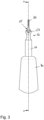
- FIG. 1 schematically a tool 1 for a medical treatment according to a first preferred embodiment is shown in a side view.
- figure 1 illustrates a tool 1 for a dental treatment, in particular a scaler for removing dental calculus.
- a tool 1 uses a vibration movement, in particular an ultrasound vibration movement for moving a tool tip 20 such that the tool tip 20, located at or next to dental calculus at a tooth, removes said dental calculus from the tooth being treated during operation.
- the tool 1 includes a vibration source 30, in particular an ultrasound vibration source, being intended to cause the ultrasound vibration movement along a vibration direction VD.
- the vibration source 30 includes at least one piezo element 31. These piezo elements 31 are typically configured such that an electrical energy can be translated to a small expansion of the piezo element 31 in vibration direction VD that creates the ultrasound vibration movement.
- the tool 1 further comprises a moving part 10 and a tool tip 20.
- the moving part 10 represents a sonotrode or horn.
- the tool tip 20 represents in figure 1 the scaler that interacts with a surface of a tooth, in particular its outside, during a treatment.
- the tool tip 20 is formed as a non-bent component.
- the tool tip 20 in form of a needle i. e. the tool tip 20 has a straight course along the extension direction ED from an inserting section, being inserted into a recess 17 in the interface section 15, to a pointed tip or distal end 6 of the tool tip 20.
- the tool tip 20 differs from the scaler tips known by the prior art that are typically bent for meeting the requirement that the rear end (seen from the vibration source) or distal end of the tool tip 20 needs to be extended slanted about an angle W of about 120° to the vibration direction VD, in particular for meeting the requirements that are defined by an oral cavity geometry.
- the tool tip 20 is connected to the moving part 10 in an interface section 15, in particular without a screwing mechanism.
- the tool tip 20 is connected to the moving part 10 in the interface section 15 by a frictional-fitting and/or form-fitting, in particular without a screwing mechanism.
- the tool tip 20 is connected to the interface section 15 of the moving part 10 by a press fit connection.
- the tool tip 20 is arranged or connected to the moving part 10 permanently or non-permanently, for example.
- the tool tip 20 is inserted into a recess 17, wherein the recess 17 is included in the moving part 10.
- the tool tip 20 extends in an extending direction ED being slanted to the vibration direction VD in the interface section 15. It turned out that by connecting a non-bent tool tip 20 such to the moving part 10 that the tool tip 20 extends slanted to the vibration direction VD of the moving part 10, it is possible to transfer the vibrational movement from the moving part 10 to the tool tip 20 in a more efficient way, compared to those scalers having a screw section for screwing the tool tip 20 to the moving part 10 of the tool.
- a non-bent, i. e. needle-like, tool tip 20 is the possibility of relying on new or different materials that, for example, are not able to be bent in a way sufficient to realize a bent tool tip 20 in form of a scaler known from the prior art.
- the extending direction ED and the vibration direction VD of the tool 1 having the non-bent tool tip 20 form an angle W that mainly corresponds to 120°, for meeting the requirements, being defined by the oral cavity geometry.
- the tool 1 has a first length L1 between a front end of the vibration source 30 and a front end of the moving part 10 being faced away from the vibration source 30, measured along the vibration direction VD. Due to the connection by a press fit in the interface section 15, it is possible to decrease a third length L3 of the tool tip 20 along the extending direction ED and/or a second length L2 of the vibration source 30 along the vibration direction VD. As a consequence, it is possible to locate the front end of the moving part 10 facing away from the vibration source 30 closer to the tooth during the treatment. This makes the energy transfer for removing the calculus even more efficient.
- a ratio of the second length L2 to the first length L1 is between 0.025 and 0.5, preferably between 0.04 and 0.13 and most preferably between 0.05 and 0.1.
- the first length L1 depends on frequency and transducer configuration and, for example for titanium material, has value between 20 and 80 mm, preferably between 30 and 70 mm and more preferably between 40 and 60 mm.
- the second length L2 has a value between 1 and 15 mm, preferably between 2 and 8 mm and most preferably between 3.5 and 7.5 mm.
- the third length L3 depends on the application.
- the third length is 20 mm for a universal tip (sub- and supragingival), but could be longer or shorter depending of the application for example shorter for high amplitude supragingival tip for example (around 14mm).
- reducing the second length L2, in particular compared to the first length L1 it is advantageously possible to produce a more compact and smaller handpiece 40 for the tool 1 that allows a much easier handling for an operator.
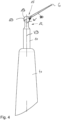
- the tool 1 for medical treatment of figure 1 including a handpiece 40, is shown in a perspective view.
- the moving part 10 reaches through a hole in a region at the rear end of the handpiece 40.
- the handpiece 40 at least partially surrounds the moving part 10 of the tool 1.
- the moving part 10 is a multi-part-system having another interface section 15' that allows removing at least a part of the moving part 10 from another section being permanently connected to the vibrational source 30.
- the needle-like, non-bent tool tip 20 tapers to its distal end 6. Furthermore, it is preferably provided that the tool tip 20 has a polygonal cross section in a plane perpendicular to the extending direction ED. For example, the cross section has a rectangular form. Furthermore, it is provided that at its rear end, i. e. its proximal end 4, the tool tip 20 has an inserting section. This inserting section is intended to be inserted into a recess 17 of the moving part 10 in a mounted state such that the tool tip 20 is connected to the moving part 10 by a press fit.
- the interface section 15 is configured as a lock and key principle that allows only those tool tips 20 to be connected to the recess 17 that have the same cross section in the inserting section that corresponds to the form of the recess 17 of the moving part 10, in particular in the interface section 15.
- the recess 17 is part of a section 13 of the moving part 10 that forms the rear end of the moving part 10, particularly being faced away from the ultrasound source 30.
- an additional opening 19 is provided at the front-end of the moving part 10 being faced away from the ultrasound vibration source 30. Such an additional opening 19 allows access, in particular visual access, to the inserting section of the tool tip 20 being inserted into the recess 17.
- the tool 1 for medical treatment in figure 1 including a headpiece 40 is shown in another side view in Figure 3 .
- the moving part 10 has a tapered section 12, being located preferably directly next to a ball- or cylinder-like section 13.
- Such a design of the moving part 10, in particular at its rear end allows concentrating the vibrational movement, caused by the vibration source 30 to the interface section 15 for a most efficient transfer of the movement energy from the moving part 10 to the tool tip 20.
- Figure 4 the tool 1 for medical treatment of Figure 1 , including the handpiece 40 is shown in the side view. It is shown that the handpiece 40 tapers along the vibrational direction VD from a proximal end to a distal end.
- FIG 5 in detail the interface section 15 of the tool 1 for medical treatment of figure 1 is shown in a side view.
- the tool tip 20 reaches through a recess 17 that is included in the ball- or cylinder- like section 13 of the rear end of the moving part 10.
- the recess 17 is slanted relative to the vibration direction VD and defines the direction of the tool tip 20, i. e. the extending direction ED of the tool tip 20 being inserted in the recess 17.
- the tool tip 20 includes a fluid channel 11, being located inside of the moving part 10, the fluid channel 11 preferably allowing the transport of the fluid from the handpiece 40 to an outlet 14 located, for example, in the interface section 15 of the tool 1 or another outlet (not shown) at the distal end 6 of the tool tip 20.
- the outlet 14 is located directly next to the recess 17 or is even part of the recess 17 that is used for connecting the tool tip 20 to the moving part 10 by a press fit.
- FIG 6 schematically a moving part 10 for a tool 1 according to a second preferred embodiment in a cross-sectional view is shown.
- the moving part 10 illustrated in figure 6 mainly differs from the moving part 10 of the tool 1 shown in the figures 1 to 5 by using a cylinder-like portion 13 that forms the rear end of the moving part 10.
- the fluid channel 11 is larger than the outlet channel 18.
- the cross section of the fluid channel 11, measured in a plane perpendicular to the stream direction is at least twice, preferably at least three times and most preferably at least four time bigger than the cross section A of the outlet channel 18, measured in a plane perpendicular to the stream direction.
- Figure 7 shows the moving part 10 of figure 6 in two perspective views.
- the cylinder-like portion 13 of the moving part 10 includes a recess 17 for receiving the tool tip 20.
- the perspective in the lower illustration shows both the recess 17 and the outlet channel 18 in a top view.
- Figure 8 shows a tool tip 20 for the moving part 10 according to the first or second embodiment of the present invention in different perspectives.
- the tool tip 20 is formed at least partially by a flat, straight tool tip 20 or needle.
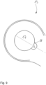
- Figure 9 shows a detailed view on the outlet 14 and the recess 17 of the moving part 10.
- figure 9 illustrates the cross section A of the outlet channel 18 of the moving part 10.
- the cross section A of the outlet opening 14 and/or the outlet channel 18 is smaller than 0.8 mm 2 or between 0.05 and 0.78 mm 2 , preferably between 0.05 and 0.39 mm 2 and most preferably between 0.05 and 0.15 mm 2 or even about 0.1 mm 2
Claims (10)
- Werkzeug (1) für eine medizinische Behandlung, insbesondere für eine zahnärztliche Behandlung, umfassend- ein Handstück (40) mit einer Vibrationsquelle (30),- ein bewegliches Teil (10), das in einem vibrierenden Zustand eine Vibrationsbewegung, insbesondere eine Ultraschallbewegung, entlang einer Vibrationsrichtung (VD) ausführt, und- eine Werkzeugspitze (20), insbesondere eine Scalerspitze, die mit dem beweglichen Teil (10) an einem Schnittstellenabschnitt (15) verbunden ist,wobei sich die Werkzeugspitze (30) in einem nicht-vibrierenden Zustand in einer Erstreckungsrichtung (ED) schräg zur Vibrationsrichtung (VD) des beweglichen Teils im Schnittstellenabschnitt (15) erstreckt, dadurch gekennzeichnet, dass die Werkzeugspitze (20) in dem Betriebszustand mit dem beweglichen Teil (10) durch eine Presspassung verbunden ist, wobei ein Winkel (W) zwischen der Vibrationsrichtung (VD) des beweglichen Teils (10) und der Erstreckungsrichtung (ED) zwischen 110° und 130° beträgt.
- Werkzeug (1) nach Anspruch 1, wobei die Werkzeugspitze (20) zumindest in einem Nichtbetriebszustand nicht gebogen ist.
- Werkzeug (1) nach einem der vorhergehenden Ansprüche, wobei die Werkzeugspitze (20) in dem Betriebszustand in eine Ausnehmung (17) des beweglichen Teils (10) eingreift und/oder diese durchgreift.
- Werkzeug nach einem der vorhergehenden Ansprüche, wobei das bewegliche Teil (10) austauschbar oder fest mit der Ultraschallquelle (30) des Handstücks (40) verbunden ist.
- Werkzeug (1) nach einem der vorhergehenden Ansprüche, wobei die Werkzeugspitze (20)- einen polygonalen Querschnitt in einem Querschnitt senkrecht zu der Erstreckungsrichtung (ED) aufweist und/oder- sich entlang ihrer Erstreckungsrichtung (ED) verjüngt.
- Werkzeug (1) nach einem der vorhergehenden Ansprüche, wobei der bewegliche Teil (10), gemessen in einer Ebene senkrecht zu der Vibrationsrichtung (VD), einen verjüngten Abschnitt (12) mit einem reduzierten Durchmesser umfasst.
- Werkzeug (1) nach einem der vorhergehenden Ansprüche, wobei das bewegliche Teil (10) einen Abschnitt (13) in dem Schnittstellenabschnitt (15) aufweist, wobei der kugelartige Abschnitt die Ausnehmung (17) zur Aufnahme der Werkzeugspitze (20) umfasst.
- Werkzeug (1) nach einem der vorhergehenden Ansprüche, wobei das bewegliche Teil (10) aus Titan gefertigt ist.
- Werkzeug (1) nach einem der vorhergehenden Ansprüche, wobei ein Verhältnis einer zweiten Länge (L2), die die in Vibrationsrichtung (VD) gemessene Länge der Vibrationsquelle (30) ist, zu einer ersten Länge (L1), die die in Vibrationsrichtung (VD) gemessene Länge des beweglichen Teils (10) ist, zwischen 0,025 und 0,5, vorzugsweise zwischen 0,04 und 0,13 und besonders bevorzugt zwischen 0,05 und 0,1 liegt.
- Werkzeug (1) nach einem der vorhergehenden Ansprüche, wobei das bewegliche Teil (10) des Handstücks (40) ein mehrteiliges System ist.
Priority Applications (10)
| Application Number | Priority Date | Filing Date | Title |
|---|---|---|---|
| EP20154169.5A EP3858286B1 (de) | 2020-01-28 | 2020-01-28 | Werkzeug für eine medizinische behandlung |
| US17/795,268 US20230066307A1 (en) | 2020-01-28 | 2021-01-28 | Tool for a medical treatment, tool tip, moving part and/or handpiece for such a tool and method for producing such a tool for a medical treatment |
| EP21702483.5A EP4096566A1 (de) | 2020-01-28 | 2021-01-28 | Instrument für eine zahnärztliche behandlung, wandler für ein solches instrument und verfahren zur herstellung eines solchen instruments |
| PCT/EP2021/052038 WO2021152049A1 (en) | 2020-01-28 | 2021-01-28 | Tool for a medical treatment, preferably a dental treatment, and method for operating such a tool |
| PCT/EP2021/052037 WO2021152048A1 (en) | 2020-01-28 | 2021-01-28 | Tool for a dental treatment, transducer for such a tool and method for assembling such a tool |
| EP21702481.9A EP4096564A1 (de) | 2020-01-28 | 2021-01-28 | Werkzeug für eine medizinische behandlung, werkzeugspitze, bewegliches teil und/oder handstück für solch ein werkzeug und verfahren zum produzieren solch eines werkzeugs für eine medizinische behandlung |
| EP21702484.3A EP4096567A1 (de) | 2020-01-28 | 2021-01-28 | Werkzeug für eine medizinische behandlung, vorzugsweise zahnärztliche behandlung, und verfahren zum betrieb eines solchen werkzeugs |
| PCT/EP2021/052034 WO2021152045A1 (en) | 2020-01-28 | 2021-01-28 | Tool for a medical treatment, tool tip, moving part and/or handpiece for such a tool and method for producing such a tool for a medical treatment |
| EP23152325.9A EP4186460A3 (de) | 2020-01-28 | 2021-01-28 | Bewegliches teil eines werkzeugs für eine medizinische behandlung, werkzeug und verfahren zur herstellung des beweglichen teils |
| CN202180011548.4A CN115038407A (zh) | 2020-01-28 | 2021-01-28 | 用于医学治疗的工具、用于这种工具的工具梢部、移动部分和/或手持件以及用于生产这种用于医学治疗的工具的方法 |
Applications Claiming Priority (1)
| Application Number | Priority Date | Filing Date | Title |
|---|---|---|---|
| EP20154169.5A EP3858286B1 (de) | 2020-01-28 | 2020-01-28 | Werkzeug für eine medizinische behandlung |
Publications (3)
| Publication Number | Publication Date |
|---|---|
| EP3858286A1 EP3858286A1 (de) | 2021-08-04 |
| EP3858286B1 true EP3858286B1 (de) | 2023-08-02 |
| EP3858286C0 EP3858286C0 (de) | 2023-08-02 |
Family
ID=69375258
Family Applications (3)
| Application Number | Title | Priority Date | Filing Date |
|---|---|---|---|
| EP20154169.5A Active EP3858286B1 (de) | 2020-01-28 | 2020-01-28 | Werkzeug für eine medizinische behandlung |
| EP23152325.9A Pending EP4186460A3 (de) | 2020-01-28 | 2021-01-28 | Bewegliches teil eines werkzeugs für eine medizinische behandlung, werkzeug und verfahren zur herstellung des beweglichen teils |
| EP21702481.9A Pending EP4096564A1 (de) | 2020-01-28 | 2021-01-28 | Werkzeug für eine medizinische behandlung, werkzeugspitze, bewegliches teil und/oder handstück für solch ein werkzeug und verfahren zum produzieren solch eines werkzeugs für eine medizinische behandlung |
Family Applications After (2)
| Application Number | Title | Priority Date | Filing Date |
|---|---|---|---|
| EP23152325.9A Pending EP4186460A3 (de) | 2020-01-28 | 2021-01-28 | Bewegliches teil eines werkzeugs für eine medizinische behandlung, werkzeug und verfahren zur herstellung des beweglichen teils |
| EP21702481.9A Pending EP4096564A1 (de) | 2020-01-28 | 2021-01-28 | Werkzeug für eine medizinische behandlung, werkzeugspitze, bewegliches teil und/oder handstück für solch ein werkzeug und verfahren zum produzieren solch eines werkzeugs für eine medizinische behandlung |
Country Status (4)
| Country | Link |
|---|---|
| US (1) | US20230066307A1 (de) |
| EP (3) | EP3858286B1 (de) |
| CN (1) | CN115038407A (de) |
| WO (1) | WO2021152045A1 (de) |
Families Citing this family (1)
| Publication number | Priority date | Publication date | Assignee | Title |
|---|---|---|---|---|
| EP4356872A1 (de) * | 2022-10-21 | 2024-04-24 | Ferton Holding S.A. | Werkzeug zum transfer einer dentalwerkzeugspitze zwischen einem montierten und einem demontierbaren zustand und verfahren zum entfernen einer dentalwerkzeugspitze von einem dentalinstrument |
Family Cites Families (11)
| Publication number | Priority date | Publication date | Assignee | Title |
|---|---|---|---|---|
| US2494825A (en) * | 1945-03-10 | 1950-01-17 | Melin William | Rotary cutting tool grinding machine |
| DE2647360A1 (de) * | 1976-10-20 | 1978-04-27 | Deckel Feinmechanik Michael | Einrichtung zum radiusbrustschleifen an schraubenverzahnten fraesern |
| US4295827A (en) * | 1979-12-31 | 1981-10-20 | Howard Martin | Endodontic flow through ultrasonic instrument holder attachment |
| US4492574A (en) * | 1983-04-15 | 1985-01-08 | Cavitron, Inc. | Ultrasonic endodontic dental apparatus |
| US4505676A (en) * | 1983-09-30 | 1985-03-19 | Dentsply Research & Development Corp. | Endodontic unit |
| US5236358A (en) * | 1992-04-27 | 1993-08-17 | Sieffert William J | Dental ultrasonic calculus removal apparatus and method |
| US20030096213A1 (en) * | 2001-11-20 | 2003-05-22 | Hickok Teresa R. | Universal ultrasonic finishing instrument |
| US6783438B2 (en) * | 2002-04-18 | 2004-08-31 | Ormco Corporation | Method of manufacturing an endodontic instrument |
| FR2876574B1 (fr) * | 2004-10-20 | 2007-11-02 | Patrick Lesage | Insert de taille pour appareil dentaire a vibrations |
| JP5483304B2 (ja) * | 2007-08-30 | 2014-05-07 | マニー株式会社 | 医療用切削具の製造装置及び製造方法 |
| EP3165193B1 (de) * | 2015-11-09 | 2020-07-15 | Ivoclar Vivadent AG | Dental-handwerkzeug |
-
2020
- 2020-01-28 EP EP20154169.5A patent/EP3858286B1/de active Active
-
2021
- 2021-01-28 WO PCT/EP2021/052034 patent/WO2021152045A1/en unknown
- 2021-01-28 EP EP23152325.9A patent/EP4186460A3/de active Pending
- 2021-01-28 US US17/795,268 patent/US20230066307A1/en active Pending
- 2021-01-28 EP EP21702481.9A patent/EP4096564A1/de active Pending
- 2021-01-28 CN CN202180011548.4A patent/CN115038407A/zh active Pending
Also Published As
| Publication number | Publication date |
|---|---|
| EP4186460A3 (de) | 2023-08-16 |
| CN115038407A (zh) | 2022-09-09 |
| US20230066307A1 (en) | 2023-03-02 |
| EP3858286A1 (de) | 2021-08-04 |
| WO2021152045A1 (en) | 2021-08-05 |
| EP4096564A1 (de) | 2022-12-07 |
| EP4186460A2 (de) | 2023-05-31 |
| EP3858286C0 (de) | 2023-08-02 |
Similar Documents
| Publication | Publication Date | Title |
|---|---|---|
| EP0217890B1 (de) | Werkzeug zum reinigen von wurzelkanälen sowie gerät zu dessen antrieb | |
| EP0874597B1 (de) | Ultraschall zahnreiniger | |
| US4505676A (en) | Endodontic unit | |
| US5094617A (en) | Dental retro-filling preparation tool and method | |
| CN112353510A (zh) | 根管治疗设备 | |
| EP3858286B1 (de) | Werkzeug für eine medizinische behandlung | |
| KR101387562B1 (ko) | 초음파 스케일러 팁 | |
| WO2008129570A1 (en) | Ultrasound frequency resonant dipole for medical use | |
| JP3703838B2 (ja) | 変換器作動のツール・チップ | |
| WO2022110495A1 (zh) | 根管治疗设备 | |
| EP4096565B1 (de) | Werkzeug für eine medizinische behandlung | |
| EP4356866A1 (de) | Spitzenhalter, werkzeugspitze und medizinisches werkzeug | |
| US20040234924A1 (en) | Waterguide design and method and tube assembly for use therewith | |
| US20020168611A1 (en) | Ultrasonic surgical dental tool having a chisel tip | |
| WO2024083763A1 (en) | A tip holder, a tool tip and a medical tool | |
| CN214049137U (zh) | 根管治疗设备 | |
| JPH1028694A (ja) | 歯科用チップ治具、およびそれを装着した歯科用チップ | |
| KR102357361B1 (ko) | 치주인대 박리용 덴탈 해머기구 | |
| JP2003079639A (ja) | 交換容易なバイブレータを備えた空気動式歯科用振動装置 | |
| JP4168420B2 (ja) | 交換容易なバイブレータを備えた空気動式歯科用振動ハンドピース | |
| JP2023551088A (ja) | ツールチップ、そうしたツールチップを備える歯科治療用のツール、及びそうしたツールの動作方法 | |
| JP6349526B2 (ja) | 歯科用振動式ハンドピースのブラシホルダーの製造方法 |
Legal Events
| Date | Code | Title | Description |
|---|---|---|---|
| PUAI | Public reference made under article 153(3) epc to a published international application that has entered the european phase |
Free format text: ORIGINAL CODE: 0009012 |
|
| STAA | Information on the status of an ep patent application or granted ep patent |
Free format text: STATUS: THE APPLICATION HAS BEEN PUBLISHED |
|
| AK | Designated contracting states |
Kind code of ref document: A1 Designated state(s): AL AT BE BG CH CY CZ DE DK EE ES FI FR GB GR HR HU IE IS IT LI LT LU LV MC MK MT NL NO PL PT RO RS SE SI SK SM TR |
|
| STAA | Information on the status of an ep patent application or granted ep patent |
Free format text: STATUS: REQUEST FOR EXAMINATION WAS MADE |
|
| 17P | Request for examination filed |
Effective date: 20220201 |
|
| RBV | Designated contracting states (corrected) |
Designated state(s): AL AT BE BG CH CY CZ DE DK EE ES FI FR GB GR HR HU IE IS IT LI LT LU LV MC MK MT NL NO PL PT RO RS SE SI SK SM TR |
|
| STAA | Information on the status of an ep patent application or granted ep patent |
Free format text: STATUS: EXAMINATION IS IN PROGRESS |
|
| 17Q | First examination report despatched |
Effective date: 20220518 |
|
| GRAP | Despatch of communication of intention to grant a patent |
Free format text: ORIGINAL CODE: EPIDOSNIGR1 |
|
| STAA | Information on the status of an ep patent application or granted ep patent |
Free format text: STATUS: GRANT OF PATENT IS INTENDED |
|
| INTG | Intention to grant announced |
Effective date: 20230227 |
|
| GRAS | Grant fee paid |
Free format text: ORIGINAL CODE: EPIDOSNIGR3 |
|
| GRAA | (expected) grant |
Free format text: ORIGINAL CODE: 0009210 |
|
| STAA | Information on the status of an ep patent application or granted ep patent |
Free format text: STATUS: THE PATENT HAS BEEN GRANTED |
|
| AK | Designated contracting states |
Kind code of ref document: B1 Designated state(s): AL AT BE BG CH CY CZ DE DK EE ES FI FR GB GR HR HU IE IS IT LI LT LU LV MC MK MT NL NO PL PT RO RS SE SI SK SM TR |
|
| REG | Reference to a national code |
Ref country code: GB Ref legal event code: FG4D |
|
| REG | Reference to a national code |
Ref country code: CH Ref legal event code: EP |
|
| REG | Reference to a national code |
Ref country code: DE Ref legal event code: R096 Ref document number: 602020014698 Country of ref document: DE |
|
| REG | Reference to a national code |
Ref country code: IE Ref legal event code: FG4D |
|
| U01 | Request for unitary effect filed |
Effective date: 20230830 |
|
| U07 | Unitary effect registered |
Designated state(s): AT BE BG DE DK EE FI FR IT LT LU LV MT NL PT SE SI Effective date: 20230906 |
|
| U20 | Renewal fee paid [unitary effect] |
Year of fee payment: 5 Effective date: 20231212 |
|
| PG25 | Lapsed in a contracting state [announced via postgrant information from national office to epo] |
Ref country code: GR Free format text: LAPSE BECAUSE OF FAILURE TO SUBMIT A TRANSLATION OF THE DESCRIPTION OR TO PAY THE FEE WITHIN THE PRESCRIBED TIME-LIMIT Effective date: 20231103 |
|
| PGFP | Annual fee paid to national office [announced via postgrant information from national office to epo] |
Ref country code: GB Payment date: 20231212 Year of fee payment: 5 |
|
| PG25 | Lapsed in a contracting state [announced via postgrant information from national office to epo] |
Ref country code: IS Free format text: LAPSE BECAUSE OF FAILURE TO SUBMIT A TRANSLATION OF THE DESCRIPTION OR TO PAY THE FEE WITHIN THE PRESCRIBED TIME-LIMIT Effective date: 20231202 |
|
| PG25 | Lapsed in a contracting state [announced via postgrant information from national office to epo] |
Ref country code: RS Free format text: LAPSE BECAUSE OF FAILURE TO SUBMIT A TRANSLATION OF THE DESCRIPTION OR TO PAY THE FEE WITHIN THE PRESCRIBED TIME-LIMIT Effective date: 20230802 Ref country code: NO Free format text: LAPSE BECAUSE OF FAILURE TO SUBMIT A TRANSLATION OF THE DESCRIPTION OR TO PAY THE FEE WITHIN THE PRESCRIBED TIME-LIMIT Effective date: 20231102 Ref country code: IS Free format text: LAPSE BECAUSE OF FAILURE TO SUBMIT A TRANSLATION OF THE DESCRIPTION OR TO PAY THE FEE WITHIN THE PRESCRIBED TIME-LIMIT Effective date: 20231202 Ref country code: HR Free format text: LAPSE BECAUSE OF FAILURE TO SUBMIT A TRANSLATION OF THE DESCRIPTION OR TO PAY THE FEE WITHIN THE PRESCRIBED TIME-LIMIT Effective date: 20230802 Ref country code: GR Free format text: LAPSE BECAUSE OF FAILURE TO SUBMIT A TRANSLATION OF THE DESCRIPTION OR TO PAY THE FEE WITHIN THE PRESCRIBED TIME-LIMIT Effective date: 20231103 |
|
| PG25 | Lapsed in a contracting state [announced via postgrant information from national office to epo] |
Ref country code: PL Free format text: LAPSE BECAUSE OF FAILURE TO SUBMIT A TRANSLATION OF THE DESCRIPTION OR TO PAY THE FEE WITHIN THE PRESCRIBED TIME-LIMIT Effective date: 20230802 |