EP3858221A1 - Fluid collecting sheaths for endoscopic devices and systems - Google Patents
Fluid collecting sheaths for endoscopic devices and systems Download PDFInfo
- Publication number
- EP3858221A1 EP3858221A1 EP21153863.2A EP21153863A EP3858221A1 EP 3858221 A1 EP3858221 A1 EP 3858221A1 EP 21153863 A EP21153863 A EP 21153863A EP 3858221 A1 EP3858221 A1 EP 3858221A1
- Authority
- EP
- European Patent Office
- Prior art keywords
- fluid
- fluid collecting
- sheath
- collecting sheath
- endoscope
- Prior art date
- Legal status (The legal status is an assumption and is not a legal conclusion. Google has not performed a legal analysis and makes no representation as to the accuracy of the status listed.)
- Pending
Links
Images




Classifications
-
- A—HUMAN NECESSITIES
- A61—MEDICAL OR VETERINARY SCIENCE; HYGIENE
- A61B—DIAGNOSIS; SURGERY; IDENTIFICATION
- A61B1/00—Instruments for performing medical examinations of the interior of cavities or tubes of the body by visual or photographical inspection, e.g. endoscopes; Illuminating arrangements therefor
- A61B1/00131—Accessories for endoscopes
- A61B1/00137—End pieces at either end of the endoscope, e.g. caps, seals or forceps plugs
-
- A—HUMAN NECESSITIES
- A61—MEDICAL OR VETERINARY SCIENCE; HYGIENE
- A61B—DIAGNOSIS; SURGERY; IDENTIFICATION
- A61B1/00—Instruments for performing medical examinations of the interior of cavities or tubes of the body by visual or photographical inspection, e.g. endoscopes; Illuminating arrangements therefor
- A61B1/012—Instruments for performing medical examinations of the interior of cavities or tubes of the body by visual or photographical inspection, e.g. endoscopes; Illuminating arrangements therefor characterised by internal passages or accessories therefor
- A61B1/015—Control of fluid supply or evacuation
-
- A—HUMAN NECESSITIES
- A61—MEDICAL OR VETERINARY SCIENCE; HYGIENE
- A61B—DIAGNOSIS; SURGERY; IDENTIFICATION
- A61B1/00—Instruments for performing medical examinations of the interior of cavities or tubes of the body by visual or photographical inspection, e.g. endoscopes; Illuminating arrangements therefor
- A61B1/303—Instruments for performing medical examinations of the interior of cavities or tubes of the body by visual or photographical inspection, e.g. endoscopes; Illuminating arrangements therefor for the vagina, i.e. vaginoscopes
-
- A—HUMAN NECESSITIES
- A61—MEDICAL OR VETERINARY SCIENCE; HYGIENE
- A61M—DEVICES FOR INTRODUCING MEDIA INTO, OR ONTO, THE BODY; DEVICES FOR TRANSDUCING BODY MEDIA OR FOR TAKING MEDIA FROM THE BODY; DEVICES FOR PRODUCING OR ENDING SLEEP OR STUPOR
- A61M1/00—Suction or pumping devices for medical purposes; Devices for carrying-off, for treatment of, or for carrying-over, body-liquids; Drainage systems
- A61M1/90—Negative pressure wound therapy devices, i.e. devices for applying suction to a wound to promote healing, e.g. including a vacuum dressing
-
- A—HUMAN NECESSITIES
- A61—MEDICAL OR VETERINARY SCIENCE; HYGIENE
- A61B—DIAGNOSIS; SURGERY; IDENTIFICATION
- A61B1/00—Instruments for performing medical examinations of the interior of cavities or tubes of the body by visual or photographical inspection, e.g. endoscopes; Illuminating arrangements therefor
- A61B1/00112—Connection or coupling means
- A61B1/00121—Connectors, fasteners and adapters, e.g. on the endoscope handle
- A61B1/00128—Connectors, fasteners and adapters, e.g. on the endoscope handle mechanical, e.g. for tubes or pipes
-
- A—HUMAN NECESSITIES
- A61—MEDICAL OR VETERINARY SCIENCE; HYGIENE
- A61B—DIAGNOSIS; SURGERY; IDENTIFICATION
- A61B1/00—Instruments for performing medical examinations of the interior of cavities or tubes of the body by visual or photographical inspection, e.g. endoscopes; Illuminating arrangements therefor
- A61B1/00131—Accessories for endoscopes
- A61B1/00135—Oversleeves mounted on the endoscope prior to insertion
-
- A—HUMAN NECESSITIES
- A61—MEDICAL OR VETERINARY SCIENCE; HYGIENE
- A61B—DIAGNOSIS; SURGERY; IDENTIFICATION
- A61B1/00—Instruments for performing medical examinations of the interior of cavities or tubes of the body by visual or photographical inspection, e.g. endoscopes; Illuminating arrangements therefor
- A61B1/00131—Accessories for endoscopes
- A61B1/0014—Fastening element for attaching accessories to the outside of an endoscope, e.g. clips, clamps or bands
-
- A—HUMAN NECESSITIES
- A61—MEDICAL OR VETERINARY SCIENCE; HYGIENE
- A61B—DIAGNOSIS; SURGERY; IDENTIFICATION
- A61B1/00—Instruments for performing medical examinations of the interior of cavities or tubes of the body by visual or photographical inspection, e.g. endoscopes; Illuminating arrangements therefor
- A61B1/012—Instruments for performing medical examinations of the interior of cavities or tubes of the body by visual or photographical inspection, e.g. endoscopes; Illuminating arrangements therefor characterised by internal passages or accessories therefor
- A61B1/018—Instruments for performing medical examinations of the interior of cavities or tubes of the body by visual or photographical inspection, e.g. endoscopes; Illuminating arrangements therefor characterised by internal passages or accessories therefor for receiving instruments
-
- A—HUMAN NECESSITIES
- A61—MEDICAL OR VETERINARY SCIENCE; HYGIENE
- A61B—DIAGNOSIS; SURGERY; IDENTIFICATION
- A61B1/00—Instruments for performing medical examinations of the interior of cavities or tubes of the body by visual or photographical inspection, e.g. endoscopes; Illuminating arrangements therefor
- A61B1/04—Instruments for performing medical examinations of the interior of cavities or tubes of the body by visual or photographical inspection, e.g. endoscopes; Illuminating arrangements therefor combined with photographic or television appliances
-
- A—HUMAN NECESSITIES
- A61—MEDICAL OR VETERINARY SCIENCE; HYGIENE
- A61B—DIAGNOSIS; SURGERY; IDENTIFICATION
- A61B1/00—Instruments for performing medical examinations of the interior of cavities or tubes of the body by visual or photographical inspection, e.g. endoscopes; Illuminating arrangements therefor
- A61B1/06—Instruments for performing medical examinations of the interior of cavities or tubes of the body by visual or photographical inspection, e.g. endoscopes; Illuminating arrangements therefor with illuminating arrangements
-
- A—HUMAN NECESSITIES
- A61—MEDICAL OR VETERINARY SCIENCE; HYGIENE
- A61B—DIAGNOSIS; SURGERY; IDENTIFICATION
- A61B34/00—Computer-aided surgery; Manipulators or robots specially adapted for use in surgery
- A61B34/30—Surgical robots
- A61B34/35—Surgical robots for telesurgery
-
- A—HUMAN NECESSITIES
- A61—MEDICAL OR VETERINARY SCIENCE; HYGIENE
- A61B—DIAGNOSIS; SURGERY; IDENTIFICATION
- A61B34/00—Computer-aided surgery; Manipulators or robots specially adapted for use in surgery
- A61B34/70—Manipulators specially adapted for use in surgery
- A61B34/71—Manipulators operated by drive cable mechanisms
-
- A—HUMAN NECESSITIES
- A61—MEDICAL OR VETERINARY SCIENCE; HYGIENE
- A61B—DIAGNOSIS; SURGERY; IDENTIFICATION
- A61B34/00—Computer-aided surgery; Manipulators or robots specially adapted for use in surgery
- A61B34/70—Manipulators specially adapted for use in surgery
- A61B34/76—Manipulators having means for providing feel, e.g. force or tactile feedback
-
- A—HUMAN NECESSITIES
- A61—MEDICAL OR VETERINARY SCIENCE; HYGIENE
- A61M—DEVICES FOR INTRODUCING MEDIA INTO, OR ONTO, THE BODY; DEVICES FOR TRANSDUCING BODY MEDIA OR FOR TAKING MEDIA FROM THE BODY; DEVICES FOR PRODUCING OR ENDING SLEEP OR STUPOR
- A61M2210/00—Anatomical parts of the body
- A61M2210/14—Female reproductive, genital organs
- A61M2210/1433—Uterus
-
- A—HUMAN NECESSITIES
- A61—MEDICAL OR VETERINARY SCIENCE; HYGIENE
- A61M—DEVICES FOR INTRODUCING MEDIA INTO, OR ONTO, THE BODY; DEVICES FOR TRANSDUCING BODY MEDIA OR FOR TAKING MEDIA FROM THE BODY; DEVICES FOR PRODUCING OR ENDING SLEEP OR STUPOR
- A61M2210/00—Anatomical parts of the body
- A61M2210/14—Female reproductive, genital organs
- A61M2210/1475—Vagina
Definitions
- the present disclosure relates to surgical instruments and, more particularly, to fluid collecting sheaths for endoscopic devices and systems.
- Tissue resection may be performed endoscopically within an organ, such as a uterus, by inserting an endoscope (or hysteroscope) into the uterus and passing a tissue resection instrument through the endoscope (or hysteroscope) and into the uterus.
- a tissue resection instrument such as a saline, sorbitol, or glycine.
- a fluid for example, saline, sorbitol, or glycine.
- the inflow and outflow of the fluid during the procedure maintains the uterus in a distended state and flushes tissue and other debris from within the uterus to maintain a visible working space.
- a pressure differential may cause fluid to leak out of the uterus through the opening through which the endoscope is inserted. Leaking fluid may travel down the length of the endoscope and drip onto the physician or the floor, presenting a hazard.
- a system in accordance with an aspect of the present disclosure, includes an endoscope defining a proximal end, a distal end and an elongated shaft extending between the proximal end and the distal end of the endoscope.
- a fluid collecting sheath defines a proximal end and a distal end. The fluid collecting sheath is configured for insertion into a vaginal opening.
- the fluid collecting sheath includes fluid collecting apertures defined at the distal end of the fluid collecting sheath.
- a fluid line is in fluid communication with the fluid collecting apertures.
- a channel is formed in the fluid collecting sheath. The channel extends between the proximal end and the distal end of the fluid collecting sheath.
- the channel defines an opening therein.
- the channel of the fluid collecting sheath is configured to operably engage the elongated shaft of the endoscope by passing the elongated shaft of the endoscope through the opening of the channel.
- the channel of the fluid collecting sheath fixedly engages the elongated shaft of the endoscope.
- the fluid collecting sheath and the endoscope move in concert with one another.
- At least one drip flange is formed at the distal end of the fluid collecting sheath.
- the at least one drip flange directs fluid away from the channel of the fluid collecting sheath.
- the system includes a collection vessel in fluid communication with the fluid line.
- the collection vessel receives fluid captured by the fluid collecting apertures.
- a collar extends from the fluid line.
- the collar is configured to be secured to the endoscope.
- the collar may be at least partially elastic.
- the fluid collecting sheath and the fluid line are a single integrally formed structure in which the fluid line extends within the fluid collecting sheath between the proximal end and the distal end of the fluid collecting sheath.
- the opening of the channel is formed through an outer edge of the fluid collecting sheath.
- the channel is configured to selectively expand in width.
- the system includes a vacuum source in fluid communication with the fluid line.
- the vacuum source applies negative pressure to the fluid collecting apertures to draw fluid through the fluid line.
- a single fluid collecting aperture may be defined at the distal end of the fluid collecting sheath.
- distal refers to the portion that is being described which is further from a user
- proximal refers to the portion that is being described which is closer to a user
- the endoscope described herein may be a hysteroscope.
- FIG. 1 shows an example endoscopic system 100 that includes an endoscopic device 104 including an elongated shaft 128 extending between a proximal end 126 and a distal end 124 of the endoscopic device 104.
- the endoscopic device 104 is connected to a fluid pump 106 and a fluid reservoir 112 (such as a saline bag) by way of a fluid line 108 that is coupled to a fluid port 120.
- the fluid pump 106 may be fluidly coupled to a separate fluid reservoir 112, or alternatively the fluid pump 106 may include a fluid reservoir.
- the fluid pump 106 may be a peristaltic pump, a positive displacement pump, or a centrifugal pump, any of which may be employed to generate fluid inflow (e.g., via negative pressure). Alternatively, the fluid pump 106 may be omitted and the fluid reservoir 112 may be in direct fluid communication with the fluid port 120, e.g., to provide fluid inflow via gravity.
- the endoscopic device 104 may further include optics, e.g., lenses and/or image capture electronics, together with an illumination source to enable visualization of a field of view emanating from distal end 124.
- the endoscopic device 104 may additionally or alternatively include a working channel to enable insertion of a working instrument, e.g., a resection device, through the endoscope 104 and into a surgical site.
- a working instrument e.g., a resection device
- the endoscopic device 104 may itself be a working instrument.
- the distal end 124 of endoscopic device 104 is inserted transvaginally through a patient's cervix and into the patient's uterus.
- the patient's cervix may expand circumferentially to accommodate the endoscopic device 104, and effectively create a seal about the endoscopic device 104.
- fluid e.g., pressurized fluid
- the cervix see, e.g., cervix 313 in FIG. 3 or cervix 413 in FIG. 4
- Leaking fluid may be collected in an under-buttocks drape, which is positioned between the patient's legs.
- the drape's function depends on correct placement of the drape throughout the procedure, and thus fluid often escapes capture.
- FIGS. 2 and 3 show a fluid collecting sheath 200 in accordance with one aspect of the present disclosure.
- An endoscopic instrument e.g., endoscope 304
- the endoscope 304 may be substantially the same as the endoscopic device 104 described with reference to FIG. 1 .
- a fluid line 202 extends from a distal end 214 of the fluid collecting sheath 200.
- the fluid line 202 forms a fluid drain 221 at the distal end 214 of the fluid collecting sheath 200.
- the fluid drain 221 is configured to drain fluid leaking through the patient's cervix 313 and passed into the patient's vagina 310.
- the suction or drain line 202 may be in fluid communication with a collection vessel 230.
- a vacuum source 240 may create negative pressure in the fluid line 202 to draw fluid into the fluid drain 221 or the fluid line 202 may transport fluid from the fluid collection sheath 200 to the collection vessel 230 under gravity.
- An outer edge 212 of the fluid collecting sheath 200 is flexible to conform to and create a seal against walls of a patient's vagina 310 and, in some cases, about the cervix 313.
- the outer edge 212 is collapsible for insertion into the vagina 310.
- the outer edge 212 of the fluid collecting sheath 200 may act as a vaginal retractor to allow visualization of the patient's cervix 313 through the proximal orifice 220.
- the fluid collecting sheath 200 may taper in diameter in a distal-to-proximal direction.
- the proximal orifice 220 may be flexible to expand and contract to various diameters to receive various sized elongated shafts 328 therein.
- the proximal orifice 220 may be dimensioned such that the endoscope 304 can move independently of the fluid collecting sheath 200.
- the fluid collecting sheath 200 may be removable, but securely fixed to the elongated shaft 328 of the endoscope 304, e.g., under resilient and/or friction fit engagement.
- FIGS. 4 to 6 show a surgical system including a fluid collecting sheath 400 in accordance with one aspect of the present disclosure.
- the system includes an endoscope 404 defining a proximal end 426, a distal end 424 and an elongated shaft 428 extending between the proximal end 426 and the distal end 424 of the endoscope 404.
- the endoscope 404 may be substantially the same as the endoscopic device 104 described with reference to FIG. 1 .
- the fluid collecting sheath 400 defines a proximal end 416 and a distal end 414.
- the fluid collecting sheath 400 is configured for insertion into a vaginal opening 410. In use, the fluid collecting sheath 400 is inserted distal end 414 first.
- the fluid collecting sheath 400 includes fluid collecting apertures 421 defined at the distal end 414 of the fluid collecting sheath 400.
- a single fluid collecting aperture 421 or a plurality of fluid collecting apertures 421 may be defined at the distal end 414 of the fluid collecting sheath 400.
- a fluid line 402 is in fluid communication with the fluid collecting apertures 421.
- the fluid collecting apertures 421 are each positioned at a lower portion of the fluid collecting sheath 400 such that gravity directs fluid toward the fluid collecting apertures 421.
- the fluid collecting apertures 421 may be positioned at a side of the fluid collecting sheath 400 substantially opposite from channel 403. As an example, the fluid collecting apertures 421 may be positioned at a lower portion of the fluid collecting sheath 400 such that gravity directs fluids toward the fluid collecting apertures 421. Fluid may additionally be pulled toward and drawn into the fluid collecting apertures 421 through negative pressure created in the fluid line 402 (e.g., by vacuum source 440).
- a channel 403 is formed in the fluid collecting sheath 400.
- the channel 403 defines a substantially circular cross-sectional shape.
- the channel 403 extends between the proximal end 416 and the distal end 414 of the fluid collecting sheath 400.
- the channel 403 defines an elongated opening 405 therein along the length thereof.
- the opening 405 may be formed at an outer edge (e.g., an upper portion) of the fluid collecting sheath 400.
- the opening 405 is configured to allow the elongated shaft 428 of the endoscope 404 to pass transversely therethrough.
- the channel 403 of the fluid collecting sheath 400 is configured to operably engage the elongated shaft 428 of the endoscope 404 by passing the elongated shaft 428 of the endoscope 404 transversely through the opening 405 of the channel 403. Radial inward pressure may be applied to the elongated shaft 428 by the sidewalls defining the channel 403.
- the channel 403 of the fluid collecting sheath 400 fixedly engages the elongated shaft 428 of the endoscope 404.
- the fluid collecting sheath 400 and the endoscope 404 move substantially in concert with one another. For example, advancing the endoscope 404 to distally advance the distal end 424 of the elongated shaft 428 will result in a corresponding distal advancement of the fluid collecting sheath 400.
- the fluid collecting sheath 400 may be configured to enable the endoscope 404 to move independently of the fluid collecting sheath 400.
- the channel 403 is configured to selectively expand in width to accommodate and operatively connect with elongated shafts of endoscopes having various widths or diameters.
- At least one drip flange may be formed at the distal end 414 of the fluid collecting sheath 400.
- the at least one drip flange directs fluid away from the channel 403 of the fluid collecting sheath 400.
- the at least one drip flange may be distally extending lip extending distally from the distal end 414 of the fluid collecting sheath 400.
- the distally extending lip including drip flanges 406 and 407 may extend distally around a distal end 434 of the channel 403, thus directing water away from the channel 403 and toward the fluid collecting apertures 421.
- a collection vessel 430 is in fluid communication with the fluid line 402.
- the collection vessel 430 receives fluid captured by the fluid collecting apertures 421 after the captured fluid has passed through the fluid line 402.
- the fluid collecting sheath 400 and the fluid line 402 may be a single integrally formed structure in which the fluid line 402 extends within the fluid collecting sheath 400 between the proximal end 416 and the distal end 414 of the fluid collecting sheath (see, e.g., FIG. 5 ).
- a vacuum source 440 may be in fluid communication with the fluid line 402.
- the vacuum source 440 may be connected with the collection vessel 430 to apply negative pressure to the fluid line 402 therethrough (see, e.g., FIG. 4 ).
- the vacuum source 440 may be connected directly with the fluid line 403.
- the vacuum source 440 applies negative pressure to the fluid collecting apertures 421 via the fluid line 402 to draw fluid into and through the fluid line 402.
- the vacuum source 440 may in some embodiments be a peristaltic pump, a positive displacement pump, or a centrifugal pump, any of which may be employed to generate fluid inflow (e.g., via negative pressure).
- fluid may be transported through fluid line 402 under gravity.
- the fluid collecting sheath 400 can be removably coupled to the endoscope 404.
- the endoscope 404 may be inserted into a vaginal opening 410 prior to the insertion of the fluid collecting sheath 400.
- the fluid collecting sheath 400 may be inserted into the vaginal opening 410 and then removably coupled to the elongated shaft 428 of the endoscope 404 to secure the fluid collecting sheath 400 to the endoscope 404 without the need to remove the endoscope 404.
- This may be achieved by applying pressure to the fluid collecting sheath 400 to force the elongated shaft 428 of the endoscope 404 transversely into the channel 403 through opening 405.
- the fluid collecting sheath 400 may include or be formed of a material (e.g., a flexible polymer) allowing sufficient bending to allow opening 405 to open sufficiently to allow elongated shaft 428 of the endoscope 404 to be securely forced into channel 403. Thus, during use the fluid collecting sheath 400 may remain substantially fixed to the endoscope 404.
- the fluid collecting sheath 400 may also be decoupled from the elongated shaft 428 of the endoscope 404 and removed without the need to remove the endoscope 404 by reversing the attachment steps described above. Thus, the fluid collecting sheath 400 may be introduced or removed as needed without the need to also remove the endoscope 404.
- a collar 650 extends from a fluid line 602.
- the fluid line 602 may be substantially the same as fluid line 402 described herein ( FIG. 4 ).
- the collar 650 is configured to be secured to an endoscope (e.g., to an elongated shaft 428 of endoscope 404 ( FIG. 4 )).
- the collar 650 may be at least partially elastic.
- the fluid line 602 may connect with fluid collecting apertures 621.
- Fluid collecting apertures 621 may be substantially the same as fluid collecting apertures 421 described herein (see FIG. 4 ).
- FIG. 7 shows a fluid collecting sheath 700 having a proximal end 716 and a distal end 714.
- Fluid collecting sheath 700 may be substantially the same as fluid collecting sheath 400 described herein, except that fluid collecting sheath 700 may have a tapered proximal end 716.
- a width of the fluid collecting sheath 700 when viewed from a top plan view may narrow gradually from the distal end 714 to the proximal end 716.
- the tapered distal end 716 may allow for easier grasping by a surgical instrument to remove fluid collecting sheath 700 from a vaginal opening.
- the various endoscopic systems disclosed herein may also be configured to work with robotic surgical systems and what is commonly referred to as "Telesurgery.”
- Such systems employ various robotic elements to assist the surgeon and allow remote operation (or partial remote operation) of surgical instrumentation.
- Various robotic arms, gears, cams, pulleys, electric and mechanical motors, etc. may be employed for this purpose and may be designed with a robotic surgical system to assist the surgeon during the course of an operation or treatment.
- Such robotic systems may include remotely steerable systems, automatically flexible surgical systems, remotely flexible surgical systems, remotely articulating surgical systems, wireless surgical systems, modular or selectively configurable remotely operated surgical systems, etc.
- the robotic surgical systems may be employed with one or more consoles that are next to the operating theater or located in a remote location.
- one team of surgeons or nurses may prep the patient for surgery and configure the robotic surgical system with one or more of the instruments disclosed herein while another surgeon (or group of surgeons) remotely control the instruments via the robotic surgical system.
- a highly skilled surgeon may perform multiple operations in multiple locations without leaving his/her remote console which can be both economically advantageous and a benefit to the patient or a series of patients.
- the robotic arms of the surgical system are typically coupled to a pair of master handles by a controller.
- the handles can be moved by the surgeon to produce a corresponding movement of the working ends of any type of surgical instrument (e.g., end effectors, graspers, knifes, scissors, etc.) which may complement the use of one or more of the endoscopic system s described herein.
- the movement of the master handles may be scaled so that the working ends have a corresponding movement that is different, smaller or larger, than the movement performed by the operating hands of the surgeon.
- the scale factor or gearing ratio may be adjustable so that the operator can control the resolution of the working ends of the surgical instrument(s).
- the master handles may include various sensors to provide feedback to the surgeon relating to various tissue parameters or conditions, e.g., tissue resistance due to manipulation, cutting or otherwise treating, pressure by the instrument onto the tissue, tissue temperature, tissue impedance, etc. As can be appreciated, such sensors provide the surgeon with enhanced tactile feedback simulating actual operating conditions.
- the master handles may also include a variety of different actuators for delicate tissue manipulation or treatment further enhancing the surgeon's ability to mimic actual operating conditions.
Landscapes
- Health & Medical Sciences (AREA)
- Life Sciences & Earth Sciences (AREA)
- Surgery (AREA)
- Heart & Thoracic Surgery (AREA)
- Public Health (AREA)
- Engineering & Computer Science (AREA)
- Biomedical Technology (AREA)
- Veterinary Medicine (AREA)
- Animal Behavior & Ethology (AREA)
- General Health & Medical Sciences (AREA)
- Physics & Mathematics (AREA)
- Radiology & Medical Imaging (AREA)
- Molecular Biology (AREA)
- Biophysics (AREA)
- Nuclear Medicine, Radiotherapy & Molecular Imaging (AREA)
- Optics & Photonics (AREA)
- Pathology (AREA)
- Medical Informatics (AREA)
- Vascular Medicine (AREA)
- Hematology (AREA)
- Anesthesiology (AREA)
- Gynecology & Obstetrics (AREA)
- Reproductive Health (AREA)
- Endoscopes (AREA)
Abstract
Description
- The present disclosure relates to surgical instruments and, more particularly, to fluid collecting sheaths for endoscopic devices and systems.
- Tissue resection may be performed endoscopically within an organ, such as a uterus, by inserting an endoscope (or hysteroscope) into the uterus and passing a tissue resection instrument through the endoscope (or hysteroscope) and into the uterus. With respect to such endoscopic tissue resection procedures, it often is desirable to distend the uterus with a fluid, for example, saline, sorbitol, or glycine. The inflow and outflow of the fluid during the procedure maintains the uterus in a distended state and flushes tissue and other debris from within the uterus to maintain a visible working space.
- During a tissue resection procedure, for example, a pressure differential may cause fluid to leak out of the uterus through the opening through which the endoscope is inserted. Leaking fluid may travel down the length of the endoscope and drip onto the physician or the floor, presenting a hazard.
- In accordance with an aspect of the present disclosure, a system includes an endoscope defining a proximal end, a distal end and an elongated shaft extending between the proximal end and the distal end of the endoscope. A fluid collecting sheath defines a proximal end and a distal end. The fluid collecting sheath is configured for insertion into a vaginal opening. The fluid collecting sheath includes fluid collecting apertures defined at the distal end of the fluid collecting sheath. A fluid line is in fluid communication with the fluid collecting apertures. A channel is formed in the fluid collecting sheath. The channel extends between the proximal end and the distal end of the fluid collecting sheath. The channel defines an opening therein. The channel of the fluid collecting sheath is configured to operably engage the elongated shaft of the endoscope by passing the elongated shaft of the endoscope through the opening of the channel.
- In some aspects, the channel of the fluid collecting sheath fixedly engages the elongated shaft of the endoscope. The fluid collecting sheath and the endoscope move in concert with one another.
- In some aspects, at least one drip flange is formed at the distal end of the fluid collecting sheath. The at least one drip flange directs fluid away from the channel of the fluid collecting sheath.
- In some aspects, the system includes a collection vessel in fluid communication with the fluid line. The collection vessel receives fluid captured by the fluid collecting apertures.
- In some aspects, a collar extends from the fluid line. The collar is configured to be secured to the endoscope. The collar may be at least partially elastic.
- In some aspects, the fluid collecting sheath and the fluid line are a single integrally formed structure in which the fluid line extends within the fluid collecting sheath between the proximal end and the distal end of the fluid collecting sheath.
- In some aspects, the opening of the channel is formed through an outer edge of the fluid collecting sheath.
- In some aspects, the channel is configured to selectively expand in width.
- In some aspects, the system includes a vacuum source in fluid communication with the fluid line. The vacuum source applies negative pressure to the fluid collecting apertures to draw fluid through the fluid line..
- In some aspects, a single fluid collecting aperture may be defined at the distal end of the fluid collecting sheath.
- The accompanying drawings, which are incorporated in and constitute a part of this specification, illustrate aspects and features of the present disclosure and, together with the detailed description below, serve to further explain the present disclosure, in which:
-
FIG. 1 shows an endoscopic system in accordance with the present disclosure; -
FIG. 2 is a side view of a fluid collecting sheath in accordance with the present disclosure; -
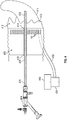
FIG. 3 illustrates the fluid collecting sheath ofFIG. 2 positioned between vaginal walls of a patient with the endoscope ofFIG. 1 extending through the fluid collecting sheath; -
FIG. 4 is a top plan view of another fluid collecting sheath in accordance with the present disclosure positioned between vaginal walls of a patient; -
FIG. 5 is a perspective view of the fluid collecting sheath ofFIG. 4 ; -
FIG. 6 is a side view of a fluid line having a collar in accordance with the present disclosure; and -
FIG. 7 is a top plan view of another fluid collecting sheath in accordance with the present disclosure. - As used herein, the term "distal" refers to the portion that is being described which is further from a user, while the term "proximal" refers to the portion that is being described which is closer to a user. Further, to the extent consistent, any of the aspects and features detailed herein may be used in conjunction with any or all of the other aspects and features detailed herein.
- Descriptions of technical features or aspects of an exemplary endoscopic system of the present disclosure should typically be considered as available and applicable to other similar features or aspects in another exemplary endoscopic system of the present disclosure. Accordingly, technical features described herein according to one exemplary endoscopic system of the present disclosure may be applicable to other exemplary endoscopic systems of the present disclosure, and thus duplicative descriptions may be omitted herein.
- Exemplary endoscopic systems of the present disclosure will be described more fully below (e.g., with reference to the accompanying drawings). Like reference numerals may refer to like elements throughout the specification and drawings.
- The endoscope described herein may be a hysteroscope.
-
FIG. 1 shows an exampleendoscopic system 100 that includes anendoscopic device 104 including anelongated shaft 128 extending between aproximal end 126 and adistal end 124 of theendoscopic device 104. In the example, theendoscopic device 104 is connected to afluid pump 106 and a fluid reservoir 112 (such as a saline bag) by way of afluid line 108 that is coupled to afluid port 120. Thefluid pump 106 may be fluidly coupled to aseparate fluid reservoir 112, or alternatively thefluid pump 106 may include a fluid reservoir. Thefluid pump 106 may be a peristaltic pump, a positive displacement pump, or a centrifugal pump, any of which may be employed to generate fluid inflow (e.g., via negative pressure). Alternatively, thefluid pump 106 may be omitted and thefluid reservoir 112 may be in direct fluid communication with thefluid port 120, e.g., to provide fluid inflow via gravity. Theendoscopic device 104 may further include optics, e.g., lenses and/or image capture electronics, together with an illumination source to enable visualization of a field of view emanating fromdistal end 124. Theendoscopic device 104 may additionally or alternatively include a working channel to enable insertion of a working instrument, e.g., a resection device, through theendoscope 104 and into a surgical site. Alternatively, theendoscopic device 104 may itself be a working instrument. - In a hysteroscopy procedure, for example, the
distal end 124 ofendoscopic device 104 is inserted transvaginally through a patient's cervix and into the patient's uterus. The patient's cervix may expand circumferentially to accommodate theendoscopic device 104, and effectively create a seal about theendoscopic device 104. During a hysteroscopy, fluid (e.g., pressurized fluid) may leak from the uterus 311 (oruterus 411 inFIG. 4 ) through the cervix (see, e.g.,cervix 313 inFIG. 3 orcervix 413 inFIG. 4 ) to a patient's vaginal area. Leaking fluid may be collected in an under-buttocks drape, which is positioned between the patient's legs. However, the drape's function depends on correct placement of the drape throughout the procedure, and thus fluid often escapes capture. -
FIGS. 2 and3 show afluid collecting sheath 200 in accordance with one aspect of the present disclosure. An endoscopic instrument, e.g.,endoscope 304, extends through aproximal orifice 220 at aproximal end 216 of thefluid collecting sheath 200 such that adistal end 324 of theendoscope 304 extends through a patient'svagina 310 and cervix 314 and into the patient'suterus 311. Theendoscope 304 may be substantially the same as theendoscopic device 104 described with reference toFIG. 1 . - A
fluid line 202 extends from adistal end 214 of thefluid collecting sheath 200. Thefluid line 202 forms afluid drain 221 at thedistal end 214 of thefluid collecting sheath 200. Thefluid drain 221 is configured to drain fluid leaking through the patient'scervix 313 and passed into the patient'svagina 310. The suction ordrain line 202 may be in fluid communication with acollection vessel 230. Avacuum source 240 may create negative pressure in thefluid line 202 to draw fluid into thefluid drain 221 or thefluid line 202 may transport fluid from thefluid collection sheath 200 to thecollection vessel 230 under gravity. - An
outer edge 212 of thefluid collecting sheath 200 is flexible to conform to and create a seal against walls of a patient'svagina 310 and, in some cases, about thecervix 313. Theouter edge 212 is collapsible for insertion into thevagina 310. Theouter edge 212 of thefluid collecting sheath 200 may act as a vaginal retractor to allow visualization of the patient'scervix 313 through theproximal orifice 220. Thefluid collecting sheath 200 may taper in diameter in a distal-to-proximal direction. - The
proximal orifice 220 may be flexible to expand and contract to various diameters to receive various sizedelongated shafts 328 therein. Theproximal orifice 220 may be dimensioned such that theendoscope 304 can move independently of thefluid collecting sheath 200. Alternatively, thefluid collecting sheath 200 may be removable, but securely fixed to theelongated shaft 328 of theendoscope 304, e.g., under resilient and/or friction fit engagement. -
FIGS. 4 to 6 show a surgical system including afluid collecting sheath 400 in accordance with one aspect of the present disclosure. The system includes anendoscope 404 defining aproximal end 426, adistal end 424 and anelongated shaft 428 extending between theproximal end 426 and thedistal end 424 of theendoscope 404. Theendoscope 404 may be substantially the same as theendoscopic device 104 described with reference toFIG. 1 . - The
fluid collecting sheath 400 defines aproximal end 416 and adistal end 414. Thefluid collecting sheath 400 is configured for insertion into avaginal opening 410. In use, thefluid collecting sheath 400 is inserteddistal end 414 first. Thefluid collecting sheath 400 includesfluid collecting apertures 421 defined at thedistal end 414 of thefluid collecting sheath 400. A singlefluid collecting aperture 421 or a plurality offluid collecting apertures 421 may be defined at thedistal end 414 of thefluid collecting sheath 400. Afluid line 402 is in fluid communication with thefluid collecting apertures 421. Thefluid collecting apertures 421 are each positioned at a lower portion of thefluid collecting sheath 400 such that gravity directs fluid toward thefluid collecting apertures 421. - The
fluid collecting apertures 421 may be positioned at a side of thefluid collecting sheath 400 substantially opposite fromchannel 403. As an example, thefluid collecting apertures 421 may be positioned at a lower portion of thefluid collecting sheath 400 such that gravity directs fluids toward thefluid collecting apertures 421. Fluid may additionally be pulled toward and drawn into thefluid collecting apertures 421 through negative pressure created in the fluid line 402 (e.g., by vacuum source 440). - A
channel 403 is formed in thefluid collecting sheath 400. Thechannel 403 defines a substantially circular cross-sectional shape. Thechannel 403 extends between theproximal end 416 and thedistal end 414 of thefluid collecting sheath 400. Thechannel 403 defines anelongated opening 405 therein along the length thereof. Theopening 405 may be formed at an outer edge (e.g., an upper portion) of thefluid collecting sheath 400. Theopening 405 is configured to allow theelongated shaft 428 of theendoscope 404 to pass transversely therethrough. Thechannel 403 of thefluid collecting sheath 400 is configured to operably engage theelongated shaft 428 of theendoscope 404 by passing theelongated shaft 428 of theendoscope 404 transversely through theopening 405 of thechannel 403. Radial inward pressure may be applied to theelongated shaft 428 by the sidewalls defining thechannel 403. - The
channel 403 of thefluid collecting sheath 400 fixedly engages theelongated shaft 428 of theendoscope 404. Thefluid collecting sheath 400 and theendoscope 404 move substantially in concert with one another. For example, advancing theendoscope 404 to distally advance thedistal end 424 of theelongated shaft 428 will result in a corresponding distal advancement of thefluid collecting sheath 400. Alternatively, thefluid collecting sheath 400 may be configured to enable theendoscope 404 to move independently of thefluid collecting sheath 400. - The
channel 403 is configured to selectively expand in width to accommodate and operatively connect with elongated shafts of endoscopes having various widths or diameters. - At least one drip flange (e.g.,
drip flanges 406 and/or 407) may be formed at thedistal end 414 of thefluid collecting sheath 400. The at least one drip flange directs fluid away from thechannel 403 of thefluid collecting sheath 400. For example, the at least one drip flange may be distally extending lip extending distally from thedistal end 414 of thefluid collecting sheath 400. The distally extending lip includingdrip flanges distal end 434 of thechannel 403, thus directing water away from thechannel 403 and toward thefluid collecting apertures 421. - A
collection vessel 430 is in fluid communication with thefluid line 402. Thecollection vessel 430 receives fluid captured by thefluid collecting apertures 421 after the captured fluid has passed through thefluid line 402. - The
fluid collecting sheath 400 and thefluid line 402 may be a single integrally formed structure in which thefluid line 402 extends within thefluid collecting sheath 400 between theproximal end 416 and thedistal end 414 of the fluid collecting sheath (see, e.g.,FIG. 5 ). - A
vacuum source 440 may be in fluid communication with thefluid line 402. Thevacuum source 440 may be connected with thecollection vessel 430 to apply negative pressure to thefluid line 402 therethrough (see, e.g.,FIG. 4 ). Alternatively, thevacuum source 440 may be connected directly with thefluid line 403. Thevacuum source 440 applies negative pressure to thefluid collecting apertures 421 via thefluid line 402 to draw fluid into and through thefluid line 402. Thevacuum source 440 may in some embodiments be a peristaltic pump, a positive displacement pump, or a centrifugal pump, any of which may be employed to generate fluid inflow (e.g., via negative pressure). Alternatively, fluid may be transported throughfluid line 402 under gravity. - According to one aspect of the disclosure, the
fluid collecting sheath 400 can be removably coupled to theendoscope 404. For example, in use, theendoscope 404 may be inserted into avaginal opening 410 prior to the insertion of thefluid collecting sheath 400. Subsequently, thefluid collecting sheath 400 may be inserted into thevaginal opening 410 and then removably coupled to theelongated shaft 428 of theendoscope 404 to secure thefluid collecting sheath 400 to theendoscope 404 without the need to remove theendoscope 404. This may be achieved by applying pressure to thefluid collecting sheath 400 to force theelongated shaft 428 of theendoscope 404 transversely into thechannel 403 throughopening 405. Thefluid collecting sheath 400 may include or be formed of a material (e.g., a flexible polymer) allowing sufficient bending to allow opening 405 to open sufficiently to allowelongated shaft 428 of theendoscope 404 to be securely forced intochannel 403. Thus, during use thefluid collecting sheath 400 may remain substantially fixed to theendoscope 404. Thefluid collecting sheath 400 may also be decoupled from theelongated shaft 428 of theendoscope 404 and removed without the need to remove theendoscope 404 by reversing the attachment steps described above. Thus, thefluid collecting sheath 400 may be introduced or removed as needed without the need to also remove theendoscope 404. - Referring particularly to
FIG. 6 , acollar 650 extends from afluid line 602. Thefluid line 602 may be substantially the same asfluid line 402 described herein (FIG. 4 ). Thecollar 650 is configured to be secured to an endoscope (e.g., to anelongated shaft 428 of endoscope 404 (FIG. 4 )). Thecollar 650 may be at least partially elastic. Thefluid line 602 may connect withfluid collecting apertures 621.Fluid collecting apertures 621 may be substantially the same asfluid collecting apertures 421 described herein (seeFIG. 4 ). -
FIG. 7 shows afluid collecting sheath 700 having aproximal end 716 and adistal end 714.Fluid collecting sheath 700 may be substantially the same asfluid collecting sheath 400 described herein, except thatfluid collecting sheath 700 may have a taperedproximal end 716. For example, a width of thefluid collecting sheath 700 when viewed from a top plan view may narrow gradually from thedistal end 714 to theproximal end 716. The tapereddistal end 716 may allow for easier grasping by a surgical instrument to removefluid collecting sheath 700 from a vaginal opening. - The various endoscopic systems disclosed herein may also be configured to work with robotic surgical systems and what is commonly referred to as "Telesurgery." Such systems employ various robotic elements to assist the surgeon and allow remote operation (or partial remote operation) of surgical instrumentation. Various robotic arms, gears, cams, pulleys, electric and mechanical motors, etc. may be employed for this purpose and may be designed with a robotic surgical system to assist the surgeon during the course of an operation or treatment. Such robotic systems may include remotely steerable systems, automatically flexible surgical systems, remotely flexible surgical systems, remotely articulating surgical systems, wireless surgical systems, modular or selectively configurable remotely operated surgical systems, etc.
- The robotic surgical systems may be employed with one or more consoles that are next to the operating theater or located in a remote location. In this instance, one team of surgeons or nurses may prep the patient for surgery and configure the robotic surgical system with one or more of the instruments disclosed herein while another surgeon (or group of surgeons) remotely control the instruments via the robotic surgical system. As can be appreciated, a highly skilled surgeon may perform multiple operations in multiple locations without leaving his/her remote console which can be both economically advantageous and a benefit to the patient or a series of patients.
- The robotic arms of the surgical system are typically coupled to a pair of master handles by a controller. The handles can be moved by the surgeon to produce a corresponding movement of the working ends of any type of surgical instrument (e.g., end effectors, graspers, knifes, scissors, etc.) which may complement the use of one or more of the endoscopic system s described herein. The movement of the master handles may be scaled so that the working ends have a corresponding movement that is different, smaller or larger, than the movement performed by the operating hands of the surgeon. The scale factor or gearing ratio may be adjustable so that the operator can control the resolution of the working ends of the surgical instrument(s).
- The master handles may include various sensors to provide feedback to the surgeon relating to various tissue parameters or conditions, e.g., tissue resistance due to manipulation, cutting or otherwise treating, pressure by the instrument onto the tissue, tissue temperature, tissue impedance, etc. As can be appreciated, such sensors provide the surgeon with enhanced tactile feedback simulating actual operating conditions. The master handles may also include a variety of different actuators for delicate tissue manipulation or treatment further enhancing the surgeon's ability to mimic actual operating conditions.
- From the foregoing and with reference to the various figure drawings, those skilled in the art will appreciate that certain modifications can also be made to the present disclosure without departing from the scope of the same. While several embodiments of the disclosure have been shown in the drawings, it is not intended that the disclosure be limited thereto, as it is intended that the disclosure be as broad in scope as the art will allow and that the specification be read likewise. Therefore, the above description should not be construed as limiting, but merely as exemplifications of particular embodiments. Those skilled in the art will envision other modifications within the scope and spirit of the claims appended hereto.
- The invention may be described by reference to the following numbered paragraphs:-
- 1. A system, comprising
an endoscope defining a proximal end, a distal end and an elongated shaft extending between the proximal end and the distal end of the endoscope;
a fluid collecting sheath defining a proximal end and a distal end, the fluid collecting sheath configured for insertion into a vaginal opening, wherein the fluid collecting sheath includes:- a plurality of fluid collecting apertures defined at the distal end of the fluid collecting sheath;
- a fluid line in fluid communication with the plurality of fluid collecting apertures; and
- a channel formed in the fluid collecting sheath, the channel extending between the proximal end and the distal end of the fluid collecting sheath, the channel defining an opening therein,
- wherein the channel of the fluid collecting sheath is configured to operably engage the elongated shaft of the endoscope therein by passing the elongated shaft of the endoscope through the opening of the channel.
- 2. The system of paragraph 1, wherein the channel of the fluid collecting sheath is configured to fixedly engage the elongated shaft of the endoscope therein, such that the fluid collecting sheath and the endoscope move in concert with one another.
- 3. The system of paragraph 1, further including at least one drip flange formed at the distal end of the fluid collecting sheath, the at least one drip flange configured to direct fluid away from the channel of the fluid collecting sheath.
- 4. The system of paragraph 1, further including a collection vessel in fluid communication with the fluid line, the collection vessel configured to receive fluid captured by the plurality of fluid collecting apertures.
- 5. The system of paragraph 1, further including a collar extending from the fluid line, the collar configured to be secured to the endoscope.
- 6. The system of paragraph 5, wherein the collar is at least partially elastic.
- 7. The system of paragraph 1, wherein the fluid collecting sheath and the fluid line are a single integrally formed structure in which the fluid line extends within the fluid collecting sheath between the proximal end and the distal end of the fluid collecting sheath.
- 8. The system of paragraph 1, wherein the opening of the channel is formed through an outer edge of the fluid collecting sheath.
- 9. The system of paragraph 1, wherein the channel is configured to selectively expand in width.
- 10. The system of paragraph 1, further including a vacuum source in fluid communication with the fluid line, the vacuum source configured to apply negative pressure to the plurality of fluid collecting apertures to draw fluid through the fluid line.
- 11. A fluid collecting sheath defining a proximal end and a distal end, the fluid collecting sheath configured for insertion into a vaginal opening, wherein the fluid collecting sheath includes:
- a plurality of fluid collecting apertures defined at the distal end of the fluid collecting sheath;
- a fluid line in fluid communication with the plurality of fluid collecting apertures; and
- a channel formed in the fluid collecting sheath, the channel extending between the proximal end and the distal end of the fluid collecting sheath, the channel defining an opening therein,
- wherein the channel of the fluid collecting sheath is configured to operably engage an elongated shaft of an endoscope therein.
- 12. The fluid collecting sheath of paragraph 11, wherein the channel of the fluid collecting sheath is configured to fixedly engage the elongated shaft of the endoscope therein, such that the fluid collecting sheath and the endoscope move in concert with one another.
- 13. The fluid collecting sheath of paragraph 11, further including at least one drip flange formed at the distal end of the fluid collecting sheath, the at least one drip flange configured to direct fluid away from the channel of the fluid collecting sheath.
- 14. The fluid collecting sheath of paragraph 11, further including a collection vessel in fluid communication with the fluid line, the collection vessel configured to receive fluid captured by the plurality of fluid collecting apertures.
- 15. The fluid collecting sheath of paragraph 11, further including a collar extending from the fluid line, the collar configured to be secured to the endoscope.
- 16. The fluid collecting sheath of paragraph 15, wherein the collar is at least partially elastic.
- 17. The fluid collecting sheath of paragraph 11, wherein the fluid collecting sheath and the fluid line are a single integrally formed structure in which the fluid line extends within the fluid collecting sheath between the proximal end and the distal end of the fluid collecting sheath.
- 18. The fluid collecting sheath of paragraph 11, wherein the opening of the channel is formed through an outer edge of the fluid collecting sheath.
- 19. The fluid collecting sheath of paragraph 11, wherein the channel is configured to selectively expand in width.
- 20. A system, comprising
an endoscope defining a proximal end, a distal end and an elongated shaft extending between the proximal end and the distal end of the endoscope;
a fluid collecting sheath defining a proximal end and a distal end, the fluid collecting sheath configured for insertion into a vaginal opening, wherein the fluid collecting sheath includes:- a fluid collecting aperture defined at the distal end of the fluid collecting sheath;
- a fluid line in fluid communication with the fluid collecting aperture; and
- a channel formed in the fluid collecting sheath, the channel extending between the proximal end and the distal end of the fluid collecting sheath, the channel defining an opening therein,
- wherein the channel of the fluid collecting sheath is configured to operably engage the elongated shaft of the endoscope therein by passing the elongated shaft of the endoscope through the opening of the channel.
Claims (9)
- A fluid collecting sheath defining a proximal end and a distal end, the fluid collecting sheath configured for insertion into a vaginal opening, wherein the fluid collecting sheath includes:at least one fluid collecting aperture defined at the distal end of the fluid collecting sheath;a fluid line in fluid communication with the at least one fluid collecting aperture; anda channel formed in the fluid collecting sheath, the channel extending between the proximal end and the distal end of the fluid collecting sheath, the channel defining an opening therein,wherein the channel of the fluid collecting sheath is configured to operably engage an elongated shaft of an endoscope therein.
- The fluid collecting sheath of claim 1, wherein the channel of the fluid collecting sheath is configured to fixedly engage the elongated shaft of the endoscope therein, such that the fluid collecting sheath and the endoscope move in concert with one another preferably further including at least one drip flange formed at the distal end of the fluid collecting sheath, the at least one drip flange configured to direct fluid away from the channel of the fluid collecting sheath.
- The fluid collecting sheath of claim 1 or 2, further including a collection vessel in fluid communication with the fluid line, the collection vessel configured to receive fluid captured by the at least one fluid collecting aperture.
- The fluid collecting sheath of claim 1, 2 or 3, further including a collar extending from the fluid line, the collar configured to be secured to the endoscope.
- The fluid collecting sheath of claim 4, wherein the collar is at least partially elastic.
- The fluid collecting sheath of any preceding claim, wherein the fluid collecting sheath and the fluid line are a single integrally formed structure in which the fluid line extends within the fluid collecting sheath between the proximal end and the distal end of the fluid collecting sheath.
- The fluid collecting sheath of any preceding claim, wherein the opening of the channel is formed through an outer edge of the fluid collecting sheath.
- The fluid collecting sheath of any preceding claim, wherein the channel is configured to selectively expand in width.
- A system, comprising
an endoscope defining a proximal end, a distal end and an elongated shaft extending between the proximal end and the distal end of the endoscope; and
a fluid collecting sheath as claimed in any preceding claim
Applications Claiming Priority (1)
| Application Number | Priority Date | Filing Date | Title |
|---|---|---|---|
| US16/778,292 US11547782B2 (en) | 2020-01-31 | 2020-01-31 | Fluid collecting sheaths for endoscopic devices and systems |
Publications (1)
| Publication Number | Publication Date |
|---|---|
| EP3858221A1 true EP3858221A1 (en) | 2021-08-04 |
Family
ID=74346866
Family Applications (1)
| Application Number | Title | Priority Date | Filing Date |
|---|---|---|---|
| EP21153863.2A Pending EP3858221A1 (en) | 2020-01-31 | 2021-01-27 | Fluid collecting sheaths for endoscopic devices and systems |
Country Status (2)
| Country | Link |
|---|---|
| US (2) | US11547782B2 (en) |
| EP (1) | EP3858221A1 (en) |
Families Citing this family (2)
| Publication number | Priority date | Publication date | Assignee | Title |
|---|---|---|---|---|
| US20180160893A1 (en) * | 2016-12-12 | 2018-06-14 | Meditrina, Inc. | Endoscope and method of use |
| GB2611108B (en) * | 2021-10-07 | 2023-10-25 | Lbn Innovations Ltd | Cervical sampling brush, cervical inspection device, and method of control thereof |
Citations (4)
| Publication number | Priority date | Publication date | Assignee | Title |
|---|---|---|---|---|
| US20070185380A1 (en) * | 2006-02-03 | 2007-08-09 | Cannuflow, Inc. | Anti-extravasation sheath |
| US20140005479A1 (en) * | 2011-03-11 | 2014-01-02 | Lohmann & Rauscher Gmbh & Co. Kg | Vacuum System and Endoscopy Arrangement for Endoscopic Vacuum Therapy |
| WO2016205126A1 (en) * | 2015-06-17 | 2016-12-22 | Covidien Lp | Endoscopic device with drip flange and methods of use thereof for an operative procedure |
| US20190246881A1 (en) * | 2018-02-12 | 2019-08-15 | Jeffrey L. Aull | Disposable Protective Sheath for Endoscope |
Family Cites Families (293)
| Publication number | Priority date | Publication date | Assignee | Title |
|---|---|---|---|---|
| US1585934A (en) | 1923-12-29 | 1926-05-25 | Radium Emanation Corp | Diagnostic needle |
| US1831786A (en) | 1926-04-20 | 1931-11-10 | California Packing Corp | Fruit peeling apparatus |
| US1666332A (en) | 1927-05-23 | 1928-04-17 | Edwin W Hirsch | Bladder-pressure-testing apparatus |
| US2708437A (en) | 1952-03-31 | 1955-05-17 | Elizabeth Painter Hutchins | Surgical instrument |
| US3297022A (en) | 1963-09-27 | 1967-01-10 | American Cystoscope Makers Inc | Endoscope |
| GB1288091A (en) | 1969-01-03 | 1972-09-06 | ||
| DE7107645U (en) | 1971-03-02 | 1971-05-27 | Storz K | ENDOSCOPE IN PARTICULAR CYSTOSCOPE |
| US3734099A (en) | 1971-04-07 | 1973-05-22 | H Bender | Powered surgical cutter |
| US3812855A (en) | 1971-12-15 | 1974-05-28 | Surgical Design Corp | System for controlling fluid and suction pressure |
| US3945375A (en) | 1972-04-04 | 1976-03-23 | Surgical Design Corporation | Rotatable surgical instrument |
| US3835842A (en) | 1972-07-03 | 1974-09-17 | J Iglesias | Endoscope with continuous irrigation |
| US3850162A (en) | 1972-07-03 | 1974-11-26 | J Iglesias | Endoscope with continuous irrigation |
| US3996921A (en) | 1975-04-17 | 1976-12-14 | Pharmacia Inc. | Method and apparatus for endoscopy |
| US4011869A (en) | 1975-08-01 | 1977-03-15 | David Kopf Instruments | Tubular cutting instrument |
| US3995619A (en) | 1975-10-14 | 1976-12-07 | Glatzer Stephen G | Combination subcutaneous suture remover, biopsy sampler and syringe |
| US3980252A (en) | 1975-10-31 | 1976-09-14 | John T. Hepburn Limited | Wire rope spooling mechanism |
| US4146405A (en) | 1977-01-19 | 1979-03-27 | Henry Timmer | Unitary dishwasher |
| US4108182A (en) | 1977-02-16 | 1978-08-22 | Concept Inc. | Reciprocation vitreous suction cutter head |
| US4198958A (en) | 1977-06-01 | 1980-04-22 | Olympus Optical Co., Ltd. | Flexible cap and instrument seal for a suction control device in an endoscope |
| US4414962A (en) | 1977-06-15 | 1983-11-15 | Carson Robert W | Operating arthroscope |
| US4203444A (en) | 1977-11-07 | 1980-05-20 | Dyonics, Inc. | Surgical instrument suitable for closed surgery such as of the knee |
| FR2415451A1 (en) | 1978-01-26 | 1979-08-24 | Bernard Parent | PANORAMIC VISION DIAGNOSTIC HYSTEROSCOPE |
| US4246902A (en) | 1978-03-10 | 1981-01-27 | Miguel Martinez | Surgical cutting instrument |
| US4210146A (en) | 1978-06-01 | 1980-07-01 | Anton Banko | Surgical instrument with flexible blade |
| US4316465A (en) | 1979-03-30 | 1982-02-23 | Dotson Robert S Jun | Ophthalmic handpiece with pneumatically operated cutter |
| US4294234A (en) | 1979-06-22 | 1981-10-13 | Olympus Optical Co., Ltd. | Endoscope |
| US4247180A (en) | 1979-08-06 | 1981-01-27 | Polaroid Corporation | Card motion picture apparatus with adjustable barrel cam |
| US4261346A (en) | 1979-11-23 | 1981-04-14 | Richard Wolf Medical Instruments Corporation | Endoscopes |
| DE2949278C2 (en) | 1979-12-07 | 1982-05-27 | Rainer Dipl.-Ing. 8261 Neuötting Kortländer | Device for knife conization of the cervix |
| US4369768A (en) | 1980-07-30 | 1983-01-25 | Marko Vukovic | Arthroscope |
| US4493698A (en) | 1980-11-03 | 1985-01-15 | Cooper Medical Devices | Method of performing opthalmic surgery utilizing a linear intra-ocular suction device |
| US4392485A (en) | 1981-02-17 | 1983-07-12 | Richard Wolf Gmbh | Endoscope |
| GB2093353B (en) | 1981-02-25 | 1984-09-19 | Dyonics Inc | A surgical instrument for arthroscopic arthroplasty |
| US4517977A (en) | 1981-07-24 | 1985-05-21 | Unisearch Limited | Co-axial tube surgical infusion/suction cutter tip |
| US4449538A (en) | 1982-01-25 | 1984-05-22 | John Corbitt | Medical-electronic body fluid accounting system |
| DE3206381C2 (en) | 1982-02-22 | 1986-07-10 | Olympus Winter & Ibe GmbH, 2000 Hamburg | Percutaneous nephroscope |
| DE3364922D1 (en) | 1982-05-28 | 1986-09-04 | Rhp Group Plc | Devices for converting rotary movement into linear movement |
| IL66047A0 (en) | 1982-06-13 | 1982-09-30 | Univ Ben Gurion | Method and device for measuring intrauterine pressure during labour |
| US5421819A (en) | 1992-08-12 | 1995-06-06 | Vidamed, Inc. | Medical probe device |
| US5435805A (en) | 1992-08-12 | 1995-07-25 | Vidamed, Inc. | Medical probe device with optical viewing capability |
| GR70998B (en) | 1982-11-03 | 1983-03-30 | Kollia Nik Georgio | |
| JPS59200644A (en) | 1983-04-27 | 1984-11-14 | オリンパス光学工業株式会社 | Surgical incision instrument |
| US4606330A (en) | 1983-08-09 | 1986-08-19 | Richard Wolf Gmbh | Device for disintegrating stones in bodily cavities or ducts |
| US4601290A (en) | 1983-10-11 | 1986-07-22 | Cabot Medical Corporation | Surgical instrument for cutting body tissue from a body area having a restricted space |
| DE3569876D1 (en) | 1984-02-20 | 1989-06-08 | Olympus Optical Co | Endoscopic ovum picker instruments |
| JPS60243625A (en) | 1984-05-18 | 1985-12-03 | Fuji Photo Optical Co Ltd | Connecting system of endoscope |
| GB2159419B (en) | 1984-05-29 | 1987-09-23 | Wolf Gmbh Richard | Uretero-renoscope |
| DE3443337A1 (en) | 1984-11-28 | 1986-05-28 | Richard Wolf Gmbh, 7134 Knittlingen | INSTRUMENT FOR THE EXAMINATION AND TREATMENT OF BODY CHANNELS |
| US4567880A (en) | 1984-12-26 | 1986-02-04 | Goodman Tobias M | Endoscopic device with three-way valve |
| US4971034A (en) | 1985-01-16 | 1990-11-20 | Asahi Kogaku Kogyo Kabushiki Kaisha | Body cavity pressure adjusting device for endoscope and laser medical treatment apparatus including body cavity pressure adjusting device |
| US4649919A (en) | 1985-01-23 | 1987-03-17 | Precision Surgical Instruments, Inc. | Surgical instrument |
| US4756309A (en) | 1985-02-14 | 1988-07-12 | Sachse Hans Ernst | Endoscope for removal of tissue |
| US4644952A (en) | 1985-02-19 | 1987-02-24 | Palm Beach Medical Engineering, Inc. | Surgical operating instrument |
| DE3601453A1 (en) | 1985-02-25 | 1986-09-04 | Hans E. Prof. Dr.Med. Sachse | Endoscope for the removal of tissue |
| JPS61259637A (en) | 1985-05-15 | 1986-11-17 | オリンパス光学工業株式会社 | Endoscope apparatus |
| JPS62105698A (en) | 1985-11-05 | 1987-05-16 | ソニー株式会社 | Printer |
| DE3615694A1 (en) | 1986-05-09 | 1987-11-12 | Winter & Ibe Olympus | Percutaneous nephroscope with safety wire |
| US4950278A (en) | 1986-08-06 | 1990-08-21 | Sachse Hans E | Endoscope for removal of tissue |
| US4749376A (en) | 1986-10-24 | 1988-06-07 | Intravascular Surgical Instruments, Inc. | Reciprocating working head catheter |
| US5312430A (en) | 1986-12-09 | 1994-05-17 | Rosenbluth Robert F | Balloon dilation catheter |
| US4867157A (en) | 1987-08-13 | 1989-09-19 | Baxter Travenol Laboratories, Inc. | Surgical cutting instrument |
| US4850354A (en) | 1987-08-13 | 1989-07-25 | Baxter Travenol Laboratories, Inc. | Surgical cutting instrument |
| US4819635A (en) | 1987-09-18 | 1989-04-11 | Henry Shapiro | Tubular microsurgery cutting apparatus |
| US4844064A (en) | 1987-09-30 | 1989-07-04 | Baxter Travenol Laboratories, Inc. | Surgical cutting instrument with end and side openings |
| US4986827A (en) | 1987-11-05 | 1991-01-22 | Nestle S.A. | Surgical cutting instrument with reciprocating inner cutter |
| FR2625428A1 (en) | 1988-01-05 | 1989-07-07 | Sinergy Sa | MULTIFUNCTIONAL OPERATIVE COELIOSCOPY DEVICE FOR PERFORMING DIFFERENT OPERATIVE GESTURES WITH INTRODUCTION OF INSTRUMENTS |
| DE3805368C1 (en) | 1988-02-17 | 1989-08-24 | Peter P. Dipl.-Ing. Wiest | |
| US4955882A (en) | 1988-03-30 | 1990-09-11 | Hakky Said I | Laser resectoscope with mechanical and laser cutting means |
| US5027792A (en) | 1989-03-17 | 1991-07-02 | Percutaneous Technologies, Inc. | Endoscopic revision hip surgery device |
| US5116868A (en) | 1989-05-03 | 1992-05-26 | The Johns Hopkins University | Effective ophthalmic irrigation solution |
| JP2787471B2 (en) | 1989-07-04 | 1998-08-20 | 旭光学工業株式会社 | Endoscope sheath device |
| US5226910A (en) | 1989-07-05 | 1993-07-13 | Kabushiki Kaisha Topcon | Surgical cutter |
| US5106364A (en) | 1989-07-07 | 1992-04-21 | Kabushiki Kaisha Topcon | Surgical cutter |
| US4998527A (en) | 1989-07-27 | 1991-03-12 | Percutaneous Technologies Inc. | Endoscopic abdominal, urological, and gynecological tissue removing device |
| US5226909A (en) | 1989-09-12 | 1993-07-13 | Devices For Vascular Intervention, Inc. | Atherectomy device having helical blade and blade guide |
| US5112299A (en) | 1989-10-25 | 1992-05-12 | Hall Surgical Division Of Zimmer, Inc. | Arthroscopic surgical apparatus and method |
| US5163433A (en) | 1989-11-01 | 1992-11-17 | Olympus Optical Co., Ltd. | Ultrasound type treatment apparatus |
| US5409013A (en) | 1989-11-06 | 1995-04-25 | Mectra Labs, Inc. | Tissue removal assembly |
| US5037386A (en) | 1989-11-17 | 1991-08-06 | Minnesota Mining And Manufacturing Company | Pressure sensing scope cannula |
| US5176677A (en) | 1989-11-17 | 1993-01-05 | Sonokinetics Group | Endoscopic ultrasonic rotary electro-cauterizing aspirator |
| US4940061A (en) | 1989-11-27 | 1990-07-10 | Ingress Technologies, Inc. | Biopsy instrument |
| US5152744A (en) | 1990-02-07 | 1992-10-06 | Smith & Nephew Dyonics | Surgical instrument |
| US5169397A (en) | 1990-02-08 | 1992-12-08 | Olympus Optical Co., Ltd. | Medical instrument |
| US5007917A (en) | 1990-03-08 | 1991-04-16 | Stryker Corporation | Single blade cutter for arthroscopic surgery |
| EP0448857A1 (en) | 1990-03-27 | 1991-10-02 | Jong-Khing Huang | An apparatus of a spinning type of resectoscope for prostatectomy |
| US5275609A (en) | 1990-06-22 | 1994-01-04 | Vance Products Incorporated | Surgical cutting instrument |
| US5269785A (en) | 1990-06-28 | 1993-12-14 | Bonutti Peter M | Apparatus and method for tissue removal |
| US5911699A (en) | 1990-07-17 | 1999-06-15 | Aziz Yehia Anis | Removal of tissue |
| US6007513A (en) | 1990-07-17 | 1999-12-28 | Aziz Yehia Anis | Removal of tissue |
| DE4038398A1 (en) | 1990-12-01 | 1992-06-04 | Schubert Werner | Medical equipment for min. invasive operation e.g. for removal of tumour - introduces knife on long handle through cylinder or tube adjusted into pathological tissue |
| US5158553A (en) | 1990-12-26 | 1992-10-27 | Cardiopulmonics | Rotatably actuated constricting catheter valve |
| EP0566694A1 (en) | 1991-01-09 | 1993-10-27 | EndoMedix Corporation | Method and device for intracorporeal liquidization of tissue and/or intracorporeal fragmentation of calculi during endoscopic surgical procedures |
| US5409453A (en) | 1992-08-12 | 1995-04-25 | Vidamed, Inc. | Steerable medical probe with stylets |
| US5125910A (en) | 1991-02-19 | 1992-06-30 | Dexide, Inc. | Surgical endoscopic suction/irrigation cannula assembly |
| US5586973A (en) | 1991-04-22 | 1996-12-24 | C & D Biomedical S.A. | Method and device for controlled irrigation and suctioning of a liquid clarificant during endoscopic surgery |
| US5490819A (en) | 1991-08-05 | 1996-02-13 | United States Surgical Corporation | Articulating endoscopic surgical apparatus |
| US5391180A (en) | 1991-08-05 | 1995-02-21 | United States Surgical Corporation | Articulating endoscopic surgical apparatus |
| EP0692266B1 (en) | 1991-08-21 | 2000-03-22 | Smith & Nephew, Inc. | Fluid management system |
| US5288290A (en) | 1991-09-25 | 1994-02-22 | Alcon Surgical, Inc. | Multi-ported valve assembly |
| US5449356A (en) | 1991-10-18 | 1995-09-12 | Birtcher Medical Systems, Inc. | Multifunctional probe for minimally invasive surgery |
| US5195541A (en) | 1991-10-18 | 1993-03-23 | Obenchain Theodore G | Method of performing laparoscopic lumbar discectomy |
| US5244459A (en) | 1992-01-28 | 1993-09-14 | Hill Raymond R | Suction irrigator endoscope |
| MX9300607A (en) | 1992-02-06 | 1993-10-01 | American Med Syst | APPARATUS AND METHOD FOR INTERSTITIAL TREATMENT. |
| US5242404A (en) | 1992-02-12 | 1993-09-07 | American Cyanamid Company | Aspiration control system |
| US5269798A (en) | 1992-02-19 | 1993-12-14 | Linvatec Corporation | Surgical cutting instrument with movable, inner and outer tubular members |
| US5254117A (en) | 1992-03-17 | 1993-10-19 | Alton Dean Medical | Multi-functional endoscopic probe apparatus |
| US5350390A (en) | 1992-03-25 | 1994-09-27 | Arieh Sher | Device for removal of intraluminal occlusions |
| US5270622A (en) | 1992-04-13 | 1993-12-14 | Smith & Nephew Dyonics, Inc. | Brushless motor control system |
| US5563481A (en) | 1992-04-13 | 1996-10-08 | Smith & Nephew Endoscopy, Inc. | Brushless motor |
| US5602449A (en) | 1992-04-13 | 1997-02-11 | Smith & Nephew Endoscopy, Inc. | Motor controlled surgical system and method having positional control |
| US5672945A (en) | 1992-04-13 | 1997-09-30 | Smith & Nephew Endoscopy, Inc. | Motor controlled surgical system and method having self clearing motor control |
| US5320091A (en) | 1992-04-27 | 1994-06-14 | Circon Corporation | Continuous flow hysteroscope |
| US5556378A (en) | 1992-06-17 | 1996-09-17 | Storz; Karl | Device for irrigation of body cavities |
| CA2101293C (en) | 1992-08-05 | 2004-06-29 | David A. Nicholas | Articulating endoscopic surgical apparatus |
| US5312399A (en) | 1992-09-29 | 1994-05-17 | Hakky Said I | Laser resectoscope with mechanical cutting means and laser coagulating means |
| SE501876C2 (en) | 1992-11-12 | 1995-06-12 | Christer Dahlstrand Ab | Motorised arrangement for endoscopic removal of prostate tissue - includes tubular body, with hand grip, channels for inspection, lighting, and input for flushing fluid for removal of fluid and cut-away tissue |
| US5304118A (en) | 1992-12-16 | 1994-04-19 | Trese Michael T | Method for performing a vitrectomy on an eye |
| US5347992A (en) | 1993-01-22 | 1994-09-20 | Karl Storz Endoscopy America, Inc. | Single axis three way selector valve for endoscopes |
| US5392765A (en) | 1993-02-11 | 1995-02-28 | Circon Corporation | Continuous flow cystoscope |
| US5403276A (en) | 1993-02-16 | 1995-04-04 | Danek Medical, Inc. | Apparatus for minimally invasive tissue removal |
| CA2121861A1 (en) | 1993-04-23 | 1994-10-24 | William D. Fox | Mechanical morcellator |
| CA2161688A1 (en) | 1993-05-07 | 1994-11-24 | Sdgi Holdings, Inc. | Surgical cutting instrument |
| US5364395A (en) | 1993-05-14 | 1994-11-15 | West Jr Hugh S | Arthroscopic surgical instrument with cauterizing capability |
| DE59400518D1 (en) | 1993-06-16 | 1996-09-26 | White Spot Ag | DEVICE FOR PUTTING FIBRINE ADHESIVE INTO A STITCH CHANNEL |
| US5395313A (en) | 1993-08-13 | 1995-03-07 | Naves; Neil H. | Reciprocating arthroscopic shaver |
| US5575756A (en) | 1993-08-16 | 1996-11-19 | Olympus Optical Co., Ltd. | Endoscope apparatus |
| US5336237A (en) | 1993-08-25 | 1994-08-09 | Devices For Vascular Intervention, Inc. | Removal of tissue from within a body cavity |
| US5425376A (en) | 1993-09-08 | 1995-06-20 | Sofamor Danek Properties, Inc. | Method and apparatus for obtaining a biopsy sample |
| US5957832A (en) | 1993-10-08 | 1999-09-28 | Heartport, Inc. | Stereoscopic percutaneous visualization system |
| US5374253A (en) | 1993-10-12 | 1994-12-20 | Burns, Sr.; Charles N. | Medical instrument with automatic shut-off valve |
| US5456689A (en) | 1993-10-13 | 1995-10-10 | Arnold J. Kresch | Method and device for tissue resection |
| WO1995010982A1 (en) | 1993-10-20 | 1995-04-27 | Correa Marco Aurelio Moura De | Surgical instrument to perform subcutaneous endoscopic surgery |
| US5443476A (en) | 1993-11-12 | 1995-08-22 | Shapiro; Henry | Microsurgical scissor apparatus with rotary cutting blade |
| DE4340056A1 (en) | 1993-11-24 | 1995-06-01 | Delma Elektro Med App | Laparoscopic surgical device |
| US5490860A (en) | 1993-12-08 | 1996-02-13 | Sofamor Danek Properties, Inc. | Portable power cutting tool |
| EP0662572B1 (en) | 1994-01-11 | 1998-04-01 | SAMJOO MACHINERY Co., Ltd. | Rotary motion/constant velocity linear reciprocating motion conversion device and hydraulic system using the same |
| US6359200B1 (en) | 1994-01-13 | 2002-03-19 | Dekalb Genetics Corp. | Inbred corn plant 8M116 |
| US5411513A (en) | 1994-02-24 | 1995-05-02 | Danek Medical, Inc. | Transmission mechanism for a surgical cutting instrument |
| US5483951A (en) | 1994-02-25 | 1996-01-16 | Vision-Sciences, Inc. | Working channels for a disposable sheath for an endoscope |
| US5456673A (en) | 1994-03-23 | 1995-10-10 | Stryker Corporation | Locking cannula for endoscopic surgery |
| US5526822A (en) | 1994-03-24 | 1996-06-18 | Biopsys Medical, Inc. | Method and apparatus for automated biopsy and collection of soft tissue |
| US5649547A (en) | 1994-03-24 | 1997-07-22 | Biopsys Medical, Inc. | Methods and devices for automated biopsy and collection of soft tissue |
| US5492537A (en) | 1994-05-03 | 1996-02-20 | Aquintel, Inc. | Surgical fluid monitor |
| US5709670A (en) | 1994-05-03 | 1998-01-20 | Aquintel, Inc. | Surgical fluid and tissue loss monitor |
| US5702420A (en) | 1994-06-14 | 1997-12-30 | Anthony R. Sterling And Tri-Tech, Inc. | Motorized suction punch forceps |
| US5669921A (en) | 1994-07-19 | 1997-09-23 | Linvatec Corporation | Endoscopic shaver blade window positioning system |
| JP2802244B2 (en) | 1994-08-29 | 1998-09-24 | オリンパス光学工業株式会社 | Endoscope sheath |
| US5498258A (en) | 1994-09-13 | 1996-03-12 | Hakky; Said I. | Laser resectoscope with laser induced mechanical cutting means |
| US5569284A (en) | 1994-09-23 | 1996-10-29 | United States Surgical Corporation | Morcellator |
| WO1996011638A1 (en) | 1994-10-13 | 1996-04-25 | Femrx | Method and device for tissue resection |
| US6032673A (en) | 1994-10-13 | 2000-03-07 | Femrx, Inc. | Methods and devices for tissue removal |
| WO1997017027A1 (en) | 1995-11-08 | 1997-05-15 | Femrx, Inc. | Electrosurgical device having rollers for ablating and segmenting of tissues |
| WO1996012453A1 (en) | 1994-10-24 | 1996-05-02 | Smith & Nephew Inc. | Hollow surgical cutter with apertured flutes |
| DE4440035C2 (en) | 1994-11-10 | 1998-08-06 | Wolf Gmbh Richard | Morcellating instrument |
| US5603332A (en) | 1995-01-27 | 1997-02-18 | Technological Services, Inc. | Method and apparatus for monitoring the systemic absorption of irrigation fluid during operative hysteroscopy |
| US5601583A (en) | 1995-02-15 | 1997-02-11 | Smith & Nephew Endoscopy Inc. | Surgical instrument |
| US5676497A (en) | 1995-02-27 | 1997-10-14 | Kim; Young S. | Power drill-saw with simultaneous rotation and reciprocation action |
| DE29503478U1 (en) | 1995-03-02 | 1995-04-20 | Richard Wolf Gmbh, 75438 Knittlingen | endoscope |
| US5810861A (en) | 1995-03-02 | 1998-09-22 | Gaber; Benny | Uterine tissue collector |
| ATE270854T1 (en) | 1995-03-31 | 2004-07-15 | Boston Scient Ltd | BIOPSY SAMPLER |
| US5873886A (en) | 1995-04-04 | 1999-02-23 | United States Surgical Corporation | Surgical cutting apparatus |
| US5569254A (en) | 1995-04-12 | 1996-10-29 | Midas Rex Pneumatic Tools, Inc. | Surgical resection tool having an irrigation, lighting, suction and vision attachment |
| US5591187A (en) | 1995-07-14 | 1997-01-07 | Dekel; Moshe | Laparoscopic tissue retrieval device and method |
| AUPN541595A0 (en) | 1995-09-13 | 1995-10-12 | Queensland University Of Technology | A surgical device |
| US5749885A (en) | 1995-10-02 | 1998-05-12 | Smith & Nephew, Inc. | Surgical instrument with embedded coding element |
| US5772634A (en) | 1995-10-06 | 1998-06-30 | Zimmer, Inc. | Device for limiting distention fluid pressure during hysteroscopy |
| DE19633124B4 (en) | 1995-11-20 | 2009-06-10 | Storz Endoskop Gmbh | Scraping or cutting instrument |
| PT805652E (en) | 1995-11-27 | 2003-02-28 | C C D Lab | DEVICE FOR THE COLLECTION OF UTERINE MUCOSES |
| US5807282A (en) | 1995-12-28 | 1998-09-15 | Mayo Foundation For Medical Education And Research | Endometrial tissue curette and method |
| US5916229A (en) | 1996-02-07 | 1999-06-29 | Evans; Donald | Rotating needle biopsy device and method |
| US5749889A (en) | 1996-02-13 | 1998-05-12 | Imagyn Medical, Inc. | Method and apparatus for performing biopsy |
| US5709698A (en) | 1996-02-26 | 1998-01-20 | Linvatec Corporation | Irrigating/aspirating shaver blade assembly |
| WO1997034534A1 (en) | 1996-03-18 | 1997-09-25 | Femrx, Inc. | Method and device for tissue vaporization and extraction |
| DE69725005T2 (en) | 1996-03-25 | 2004-06-17 | Safe Conduct Ab | DEVICE FOR TAKING TISSUE OR THE LIKE |
| DE19706751A1 (en) | 1996-03-27 | 1997-10-02 | Valleylab Inc | Electrosurgical device for removing tissue in body areas |
| US5766199A (en) | 1996-04-10 | 1998-06-16 | Linvatec Corporation | Endoscopic shaver blade with resilient cutting edges |
| BE1010290A3 (en) | 1996-05-10 | 1998-05-05 | Saturnus Ag | TISSUE-morcellator. |
| US5833643A (en) | 1996-06-07 | 1998-11-10 | Scieran Technologies, Inc. | Apparatus for performing ophthalmic procedures |
| US5741286A (en) | 1996-06-07 | 1998-04-21 | Symbiosis Corporation | Laparoscopic instrument kit including a plurality of rigid tubes |
| US6258111B1 (en) | 1997-10-03 | 2001-07-10 | Scieran Technologies, Inc. | Apparatus and method for performing ophthalmic procedures |
| US6113594A (en) | 1996-07-02 | 2000-09-05 | Ethicon, Inc. | Systems, methods and apparatus for performing resection/ablation in a conductive medium |
| US5857995A (en) | 1996-08-15 | 1999-01-12 | Surgical Dynamics, Inc. | Multiple bladed surgical cutting device removably connected to a rotary drive element |
| US6017354A (en) | 1996-08-15 | 2000-01-25 | Stryker Corporation | Integrated system for powered surgical tools |
| US5769794A (en) | 1996-09-04 | 1998-06-23 | Smith & Nephew Endoscopy, Inc | Tissue retrieval bag and method for removing cancerous tissue |
| SE509513C2 (en) | 1996-09-16 | 1999-02-08 | Endolink Ab | Tools for use in surgical procedures on the uterus and cervix |
| US5807240A (en) | 1996-09-24 | 1998-09-15 | Circon Corporation | Continuous flow endoscope with enlarged outflow channel |
| US6090094A (en) | 1996-10-04 | 2000-07-18 | Microgroup, Inc. | Ball valves and uses thereof including endoscopic surgical instruments |
| US5814009A (en) | 1996-10-11 | 1998-09-29 | Cabot Technology Corporation | Fluid management system and replaceable tubing assembly therefor |
| US5730752A (en) | 1996-10-29 | 1998-03-24 | Femrx, Inc. | Tubular surgical cutters having aspiration flow control ports |
| US5741287A (en) | 1996-11-01 | 1998-04-21 | Femrx, Inc. | Surgical tubular cutter having a tapering cutting chamber |
| US5899915A (en) | 1996-12-02 | 1999-05-04 | Angiotrax, Inc. | Apparatus and method for intraoperatively performing surgery |
| US5810770A (en) | 1996-12-13 | 1998-09-22 | Stryker Corporation | Fluid management pump system for surgical procedures |
| US5913867A (en) | 1996-12-23 | 1999-06-22 | Smith & Nephew, Inc. | Surgical instrument |
| US5947990A (en) | 1997-02-24 | 1999-09-07 | Smith & Nephew, Inc. | Endoscopic surgical instrument |
| US6024751A (en) | 1997-04-11 | 2000-02-15 | Coherent Inc. | Method and apparatus for transurethral resection of the prostate |
| US6156049A (en) | 1997-04-11 | 2000-12-05 | Coherent Inc. | Method and apparatus for transurethral resection of the prostate |
| US5925055A (en) | 1997-06-23 | 1999-07-20 | Medelex, Inc | Multimodal rotary abrasion and acoustic ablation catheter |
| US6086542A (en) | 1997-07-01 | 2000-07-11 | Linvatec Corporation | Pressure sensing input/output scope sheath |
| US5928249A (en) * | 1997-07-11 | 1999-07-27 | Gynecare, Inc. | Cervical dam |
| US6149633A (en) | 1997-07-15 | 2000-11-21 | Surgin Surgical Instrumentation, Inc. | Flow control system and method for endoscopic surgeries |
| JP2001510066A (en) | 1997-07-18 | 2001-07-31 | ガイラス・メディカル・リミテッド | Electrosurgical instrument |
| EP0996378B1 (en) | 1997-07-18 | 2004-06-30 | Gyrus Medical Limited | An electrosurgical instrument |
| US6039748A (en) | 1997-08-05 | 2000-03-21 | Femrx, Inc. | Disposable laparoscopic morcellator |
| NL1006944C2 (en) | 1997-09-04 | 1999-03-11 | Mark Hans Emanuel | Surgical endoscopic cutting device. |
| US6004320A (en) | 1997-09-19 | 1999-12-21 | Oratec Interventions, Inc. | Clip on electrocauterizing sheath for orthopedic shave devices |
| US6102895A (en) | 1997-09-30 | 2000-08-15 | Cortella; Julian M. | Digital fluid delivery and aspiration apparatus with mechanical de-amplifier |
| DE19751632C1 (en) | 1997-11-21 | 1999-09-16 | Aesculap Ag & Co Kg | Hysteroscope for examination of cervical canals |
| JP2002502626A (en) | 1998-02-10 | 2002-01-29 | アーテミス・メディカル・インコーポレイテッド | Supplementary device and method of using the same |
| US6331166B1 (en) | 1998-03-03 | 2001-12-18 | Senorx, Inc. | Breast biopsy system and method |
| US6659105B2 (en) | 1998-02-26 | 2003-12-09 | Senorx, Inc. | Tissue specimen isolating and damaging device and method |
| US6344026B1 (en) | 1998-04-08 | 2002-02-05 | Senorx, Inc. | Tissue specimen encapsulation device and method thereof |
| US6159160A (en) | 1998-03-26 | 2000-12-12 | Ethicon, Inc. | System and method for controlled infusion and pressure monitoring |
| US6156043A (en) | 1998-05-26 | 2000-12-05 | Krahn; Henry P. | Soft tissue morsellator |
| US6224603B1 (en) | 1998-06-09 | 2001-05-01 | Nuvasive, Inc. | Transiliac approach to entering a patient's intervertebral space |
| US6132448A (en) | 1998-06-19 | 2000-10-17 | Stryker Corporation | Endoscopic irrigated bur |
| US5911722A (en) | 1998-07-23 | 1999-06-15 | Millenium Devices Llc | Leban/Gordon surgical hand driver |
| US6068641A (en) | 1998-08-25 | 2000-05-30 | Linvatec Corporation | Irrigated burr |
| US6136014A (en) | 1998-09-01 | 2000-10-24 | Vivant Medical, Inc. | Percutaneous tissue removal device |
| US6245084B1 (en) | 1998-10-20 | 2001-06-12 | Promex, Inc. | System for controlling a motor driven surgical cutting instrument |
| US6494892B1 (en) | 1998-10-20 | 2002-12-17 | Suros Surgical Systems, Inc. | Disposable hub for a surgical cutting instrument |
| US6632182B1 (en) | 1998-10-23 | 2003-10-14 | The Trustees Of Columbia University In The City Of New York | Multiple bit, multiple specimen endoscopic biopsy forceps |
| JP3448228B2 (en) | 1998-11-30 | 2003-09-22 | 富士写真光機株式会社 | Endoscope insertion guide tube |
| US6244228B1 (en) | 1998-12-11 | 2001-06-12 | Damon Kuhn | Rotary-to-linear motion converter and use thereof |
| US6119973A (en) | 1999-01-29 | 2000-09-19 | Owens Corning Fiberglas Technology, Inc. | Reciprocating apparatus and cam follower for winding a package |
| EP1152684B1 (en) | 1999-02-18 | 2003-12-17 | Karl Storz GmbH & Co. KG | Endoscope |
| US20020165427A1 (en) | 1999-03-15 | 2002-11-07 | Daniel Yachia | Intravesicular device |
| US6120147A (en) | 1999-03-17 | 2000-09-19 | Dutch Ophthalmic Research Center International Bv | Vitrectomy lens |
| US6159209A (en) | 1999-03-18 | 2000-12-12 | Canox International Ltd. | Automatic resectoscope |
| US6402701B1 (en) | 1999-03-23 | 2002-06-11 | Fna Concepts, Llc | Biopsy needle instrument |
| US6066153A (en) | 1999-03-31 | 2000-05-23 | Lev; Avigdor | Device and method for resecting body tissues |
| US6120462A (en) | 1999-03-31 | 2000-09-19 | Ethicon Endo-Surgery, Inc. | Control method for an automated surgical biopsy device |
| US7128708B2 (en) | 2002-06-13 | 2006-10-31 | Usgi Medical Inc. | Shape lockable apparatus and method for advancing an instrument through unsupported anatomy |
| US6358200B1 (en) | 1999-09-01 | 2002-03-19 | Circon Corporation | Continuous flow resectoscope with single tube sheath assembly and rotatable connection |
| JP2001075416A (en) | 1999-09-03 | 2001-03-23 | Konica Corp | Image forming device |
| US6368324B1 (en) | 1999-09-24 | 2002-04-09 | Medtronic Xomed, Inc. | Powered surgical handpiece assemblies and handpiece adapter assemblies |
| SE9904223D0 (en) | 1999-11-19 | 1999-11-19 | Safe Conduct Ab | Working Device |
| JP2001149374A (en) | 1999-11-29 | 2001-06-05 | Asahi Optical Co Ltd | Endoscope tissue collection tool |
| WO2001058368A1 (en) | 2000-02-10 | 2001-08-16 | Harmonia Medical Technologies Inc. | Transurethral volume reduction of the prostate (tuvor) |
| US6626827B1 (en) | 2000-09-01 | 2003-09-30 | C. R. Bard, Inc. | Fluid management assembly for use in endoscopic procedures |
| AU2001270943A1 (en) | 2000-06-14 | 2001-12-24 | Harmonia Medical Technologies, INC | Surgical instrument and method of using the same |
| US6712773B1 (en) | 2000-09-11 | 2004-03-30 | Tyco Healthcare Group Lp | Biopsy system |
| WO2002069808A2 (en) | 2000-11-06 | 2002-09-12 | Suros Surgical Systems, Inc. | Biopsy apparatus |
| US20030050603A1 (en) | 2001-09-12 | 2003-03-13 | Todd Erik F. | Cannula that provides bi-directional fluid flow that is regulated by a single valve |
| US7226459B2 (en) | 2001-10-26 | 2007-06-05 | Smith & Nephew, Inc. | Reciprocating rotary arthroscopic surgical instrument |
| US7510563B2 (en) | 2001-10-26 | 2009-03-31 | Smith & Nephew, Inc. | Reciprocating rotary arthroscopic surgical instrument |
| DE10164384A1 (en) | 2001-12-28 | 2003-07-17 | Wolf Gmbh Richard | Hysteroscope with alternating shaft system |
| JP4056760B2 (en) | 2002-02-22 | 2008-03-05 | ペンタックス株式会社 | Endoscope suction switching mechanism |
| DE50301103D1 (en) | 2002-03-19 | 2005-10-06 | Bard Dublin Itc Ltd | VACUUM BIOPSY DEVICE |
| DE10310614B4 (en) | 2002-03-25 | 2007-10-11 | Richard Wolf Gmbh | resectoscope |
| EP1603462B1 (en) | 2003-02-25 | 2015-07-15 | Devicor Medical Products, Inc. | Biopsy device with variable speed cutter advance |
| US7150713B2 (en) | 2003-10-16 | 2006-12-19 | Smith & Nephew, Inc. | Endoscopic device |
| DE10358279A1 (en) | 2003-12-11 | 2005-07-14 | Karl Storz Gmbh & Co. Kg | Medical instrument for cutting biological and especially human tissue |
| US7500947B2 (en) | 2004-01-29 | 2009-03-10 | Cannonflow, Inc. | Atraumatic arthroscopic instrument sheath |
| US7413542B2 (en) | 2004-01-29 | 2008-08-19 | Cannuflow, Inc. | Atraumatic arthroscopic instrument sheath |
| US20050228417A1 (en) | 2004-03-26 | 2005-10-13 | Teitelbaum George P | Devices and methods for removing a matter from a body cavity of a patient |
| US8062214B2 (en) | 2004-08-27 | 2011-11-22 | Smith & Nephew, Inc. | Tissue resecting system |
| US7806871B2 (en) | 2005-05-09 | 2010-10-05 | Boston Scientific Scimed, Inc. | Method and device for tissue removal and for delivery of a therapeutic agent or bulking agent |
| US20060251581A1 (en) | 2005-05-09 | 2006-11-09 | Mcintyre Jon T | Method for treatment of uterine fibroid tumors |
| US8932208B2 (en) | 2005-05-26 | 2015-01-13 | Maquet Cardiovascular Llc | Apparatus and methods for performing minimally-invasive surgical procedures |
| DE202005008569U1 (en) | 2005-06-01 | 2005-09-08 | Polydiagnost Gmbh | Endoscopic instrument, comprising specifically arranged optical device, lighting device, and rinsing duct |
| US20070173736A1 (en) | 2005-10-07 | 2007-07-26 | Femspec Llc | Apparatus and methods for endometrial biopsies |
| US8915842B2 (en) * | 2008-07-14 | 2014-12-23 | Ethicon Endo-Surgery, Inc. | Methods and devices for maintaining visibility and providing irrigation and/or suction during surgical procedures |
| WO2008033356A2 (en) | 2006-09-11 | 2008-03-20 | Karl Storz Endovision, Inc. | System and method for an hysteroscope with integrated instruments |
| US8840625B2 (en) | 2006-10-18 | 2014-09-23 | Hologic, Inc. | Systems for performing gynecological procedures with closed visualization lumen |
| US8025656B2 (en) | 2006-11-07 | 2011-09-27 | Hologic, Inc. | Methods, systems and devices for performing gynecological procedures |
| US9392935B2 (en) | 2006-11-07 | 2016-07-19 | Hologic, Inc. | Methods for performing a medical procedure |
| US20080262308A1 (en) | 2007-02-27 | 2008-10-23 | Percutaneaus Systems, Inc. | Method and system for performing continuous flow endoscopy |
| US9259233B2 (en) | 2007-04-06 | 2016-02-16 | Hologic, Inc. | Method and device for distending a gynecological cavity |
| EP2134283B1 (en) | 2007-04-06 | 2014-06-11 | Hologic, Inc. | System and device for tissue removal |
| US20090270898A1 (en) | 2007-04-06 | 2009-10-29 | Interlace Medical, Inc. | Tissue removal device with high reciprocation rate |
| US9095366B2 (en) | 2007-04-06 | 2015-08-04 | Hologic, Inc. | Tissue cutter with differential hardness |
| US20090005750A1 (en) * | 2007-06-27 | 2009-01-01 | Beverley West | Discharge absorbing apparatus |
| US20110166419A1 (en) | 2008-06-27 | 2011-07-07 | Matthias Reif | Endoscope having a shaft tube and optic |
| US8262563B2 (en) | 2008-07-14 | 2012-09-11 | Ethicon Endo-Surgery, Inc. | Endoscopic translumenal articulatable steerable overtube |
| EP2330982A2 (en) | 2008-09-24 | 2011-06-15 | Hologic, Inc. | Systems, methods and devices for using a flowable medium for distending a hollow organ |
| US9572921B2 (en) | 2008-12-17 | 2017-02-21 | Smith & Nephew, Inc. | Cartridge assembly |
| EP2482912B1 (en) * | 2009-09-30 | 2019-10-23 | Lohmann & Rauscher GmbH & Co. KG | Vacuum sponge drainage |
| EP2498668A4 (en) | 2009-11-13 | 2013-08-07 | Hologic Inc | ACCESS SYSTEM WITH REMOVABLE EVACUATION CHANNEL |
| US8465421B2 (en) | 2009-12-14 | 2013-06-18 | C2Cure Inc. | Endoscope with an improved working channel |
| WO2012032837A1 (en) | 2010-09-10 | 2012-03-15 | オリンパスメディカルシステムズ株式会社 | Endoscope |
| US9155454B2 (en) | 2010-09-28 | 2015-10-13 | Smith & Nephew, Inc. | Hysteroscopic system |
| US8986269B2 (en) * | 2010-11-11 | 2015-03-24 | Ulcerx Medical Inc. | Wound leakage vacuum collection device |
| US8911424B2 (en) * | 2011-02-09 | 2014-12-16 | Ethicon, Inc. | Methods and devices for preventing catheter related urinary tract infections |
| RU2562680C2 (en) * | 2011-03-11 | 2015-09-10 | Ломанн Унд Раушер Гмбх Унд Ко. Кг | Vacuum system and endoscopic system for endoscopic vacuum-therapy |
| US9060760B2 (en) | 2011-08-18 | 2015-06-23 | Hologic, Inc. | Tissue removal system |
| AU2013204083B2 (en) * | 2012-06-03 | 2016-02-25 | Daniel Eduard Kleiner | Endoluminal vacuum therapy device |
| KR101980314B1 (en) | 2012-06-28 | 2019-05-20 | 에스케이하이닉스 주식회사 | Memory device and operation method of the same |
| DE102014005679A1 (en) | 2014-04-16 | 2015-10-22 | Lohmann & Rauscher Gmbh & Co. Kg | Drainage and vacuum pump for intrauterine negative pressure therapy |
| JP7082052B2 (en) * | 2015-09-03 | 2022-06-07 | ネプチューン メディカル インク. | A device for advancing the endoscope in the small intestine |
| EP3468490B1 (en) * | 2016-06-09 | 2022-08-17 | ConMed Corporation | Uterine manipulator |
| EP3618726A1 (en) * | 2017-05-02 | 2020-03-11 | Ambu A/S | An endoscope |
| EP3796853A4 (en) * | 2018-05-19 | 2022-03-30 | Crafton, Ashley | HANNAH CERVICAL CUT |
| KR102697367B1 (en) * | 2019-04-09 | 2024-08-20 | 에이엔엑스 로보티카 코포레이션 | Systems and methods for liquid biopsy and drug delivery |
-
2020
- 2020-01-31 US US16/778,292 patent/US11547782B2/en active Active
-
2021
- 2021-01-27 EP EP21153863.2A patent/EP3858221A1/en active Pending
-
2022
- 2022-12-05 US US18/075,060 patent/US20230100492A1/en active Pending
Patent Citations (4)
| Publication number | Priority date | Publication date | Assignee | Title |
|---|---|---|---|---|
| US20070185380A1 (en) * | 2006-02-03 | 2007-08-09 | Cannuflow, Inc. | Anti-extravasation sheath |
| US20140005479A1 (en) * | 2011-03-11 | 2014-01-02 | Lohmann & Rauscher Gmbh & Co. Kg | Vacuum System and Endoscopy Arrangement for Endoscopic Vacuum Therapy |
| WO2016205126A1 (en) * | 2015-06-17 | 2016-12-22 | Covidien Lp | Endoscopic device with drip flange and methods of use thereof for an operative procedure |
| US20190246881A1 (en) * | 2018-02-12 | 2019-08-15 | Jeffrey L. Aull | Disposable Protective Sheath for Endoscope |
Also Published As
| Publication number | Publication date |
|---|---|
| US20230100492A1 (en) | 2023-03-30 |
| US20210236702A1 (en) | 2021-08-05 |
| US11547782B2 (en) | 2023-01-10 |
Similar Documents
| Publication | Publication Date | Title |
|---|---|---|
| US9375207B2 (en) | Atraumatic arthroscopic instrument sheath | |
| US7771384B2 (en) | Trocar with integral irrigation and suction tube | |
| US5195541A (en) | Method of performing laparoscopic lumbar discectomy | |
| KR102353576B1 (en) | Method and apparatus for manipulating the side wall of a body lumen or body cavity so as to provide increased visualization of the same and/or increased access to the same, and/or for stabilizing instruments relative to the same | |
| EP1003424B1 (en) | Disposable laparoscopic morcellator | |
| US20160262785A1 (en) | Devices and methods for resecting soft tissue | |
| JP2021098086A (en) | Clip collar advanced fixation | |
| JP7158037B2 (en) | Methods and apparatus for manipulating the sidewalls of body cavities or cavities | |
| US5578031A (en) | Laparoscopic instrument assembly and associated method | |
| CN101888805A (en) | laparoscopic tissue retractor | |
| US20230100492A1 (en) | Fluid collecting sheaths for endoscopic devices and systems | |
| CN113038862B (en) | Devices used to retract tissue under endoscopy | |
| US20110105838A1 (en) | Suction device for endoscopic instruments and method | |
| US8021355B2 (en) | System, kit, and method of transgastric removal of visceral fat and other related methods | |
| KR20120042136A (en) | Apparatus with duoble snare for polyp resection | |
| WO1993008867A2 (en) | Apparatus for laparoscopic and endoscopic surgery | |
| US11129672B2 (en) | Tissue resecting device including an articulatable cutting member | |
| EP2976020B1 (en) | A miniature robotic device applicable to a flexible endoscope for the surgical dissection of gastro-intestinal tract surface neoplasms | |
| US20240349992A1 (en) | Imaging device with elongate arm and pivotable camera | |
| US20220015790A1 (en) | Tissue resecting instrument including an outflow control seal | |
| US20210353328A1 (en) | Surgical system use flow and tools | |
| WO2023026074A1 (en) | Imaging device with elongate arm and pivotable camera | |
| US20140135809A1 (en) | Expandable member dissection port and related methods | |
| US20110105842A1 (en) | Suction device for laparoscopic instruments and method | |
| US20210307771A1 (en) | Articulating lumen with a grasping end effector |
Legal Events
| Date | Code | Title | Description |
|---|---|---|---|
| PUAI | Public reference made under article 153(3) epc to a published international application that has entered the european phase |
Free format text: ORIGINAL CODE: 0009012 |
|
| STAA | Information on the status of an ep patent application or granted ep patent |
Free format text: STATUS: THE APPLICATION HAS BEEN PUBLISHED |
|
| AK | Designated contracting states |
Kind code of ref document: A1 Designated state(s): AL AT BE BG CH CY CZ DE DK EE ES FI FR GB GR HR HU IE IS IT LI LT LU LV MC MK MT NL NO PL PT RO RS SE SI SK SM TR |
|
| STAA | Information on the status of an ep patent application or granted ep patent |
Free format text: STATUS: REQUEST FOR EXAMINATION WAS MADE |
|
| 17P | Request for examination filed |
Effective date: 20220110 |
|
| RBV | Designated contracting states (corrected) |
Designated state(s): AL AT BE BG CH CY CZ DE DK EE ES FI FR GB GR HR HU IE IS IT LI LT LU LV MC MK MT NL NO PL PT RO RS SE SI SK SM TR |
|
| STAA | Information on the status of an ep patent application or granted ep patent |
Free format text: STATUS: EXAMINATION IS IN PROGRESS |
|
| 17Q | First examination report despatched |
Effective date: 20230816 |